1. Introduction
Staying competitive in industry requires to reduce production costs and increase production rates. For robotic manipulators in pick-and-place applications in the semi-conductor and packaging industry, for example, this requires the minimization of the cycle times. Reducing cycle times, in general, requires higher speeds and accelerations, which on the other hand may worsen vibration phenomena and lead to increased settling times and a reduced precision. The settling time is defined as the time to reach and stay within a certain error band of the final position after a motion is initiated. A longer settling time means that additional waiting time is added to the cycle for vibrations to die out. Multiple design approaches exist to achieve optimal settling time in multiple degree-of-freedom (DoF) manipulators [
1,
2,
3]. These approaches focus on the manipulator solely and assume the base to be rigid. In reality, however, the base is elastic and therefore vibrations in the base can also affect the precision and the settling time significantly [
4], not only of itself but also of surrounding machinery.
Base vibrations can be minimized with dynamic balancing, by which its source, the fluctuating reaction forces and moments exerted by the manipulator on its base, are eliminated. In fact, dynamic balancing leads to a dynamic decoupling between the mechanism and its base, for which there is no need for force frames and vibration isolation [
5]. A manipulator or mechanism is considered dynamically balanced when both the sum of linear momentum and the sum of angular momentum stay constant during motions. A disadvantage of dynamic balance solutions often is that significant mass and inertia needs to be added to the mechanism, which degenerates the dynamical properties and the natural frequencies [
6,
7] and increases the settling time. It is therefore key to find designs which are dynamically balanced with low additional mass and inertia and have significantly high natural frequencies in order to achieve low settling times.
The literature on dynamic balancing is predominantly theoretical and the majority of the published experiments does not take the dynamic properties into account [
8,
9,
10]. The experimentally verified high speed dynamically balanced manipulators which can be found are the DUAL-V and Hummingbird manipulator. The DUAL-V manipulator [
11] relies on actuation redundancy and is based on a duplicate pantograph architecture. Accelerations over 10 G were reached during experiments with a 17 cm motion distance. The Hummingbird [
12] is a force-balanced manipulator with a separately controlled reaction wheel for moment balancing, an approach which is known as active balancing. Accelerations up to 50 G were achieved for 5 mm motion distance and the first natural frequency of the mechanism showed 1.3 kHz. The active moment balancing in the Hummingbird resulted in a 90% reduction of the reaction moment, which is relatively low due to non-ideal actuators and limited control performance. For a much larger manipulator comparable to the Hummingbird, accelerations up to 10 G were reported with 25 cm motion distance; however, no further experimental information was published [
13,
14].
The goal of this paper is to present and to experimentally verify a structural design of a manipulator arm with high natural frequencies that is based on a dynamically balanced inverted four-bar linkage. The dynamically balanced inverted four-bar linkage was found by Ricard and Gosselin in 2000 [
15] and can be considered a 1-DoF inherently dynamically balanced mechanism as it needs—besides a specific mass distribution—no additional counter rotating inertia (counter-inertia) for moment balance. If one link of the four-bar linkage is regarded as the manipulator arm, with the other elements solely for balancing, then the design can be used as a building block in the design of multi-DoF dynamically balanced manipulators [
16].
In
Section 2 the dynamically balanced inverted four-bar linkage is introduced.
Section 3 presents the design of the manipulator arm with the investigation of the natural frequencies. In
Section 4 the robustness to manufacturing tolerances of the designed mechanism is evaluated. The experimental setup and the experimental results are presented in
Section 5 and
Section 6, respectively, with a discussion in
Section 7.
2. Mechanism of the Balanced Manipulator Arm
2.1. Architecture of the Balanced Manipulator Arm
Achieving dynamic balance with counter rotating flywheel based architectures, in general, requires a rotary transmission such as a pair of gears or a belt drive. Such a transmission adds mass, compliance, and backlash to the mechanism, which affect the dynamic properties and the settling times negatively. In contrast, inherently balanced architectures, such as the dynamically balanced inverted four-bar linkage, only require a specific distribution of masses and inertias of its links without the need for additional elements. The balanced inverted four-bar linkage is a closed loop mechanism which has the highest concentration of its masses and inertias located close to the base pivots or on the coupler link, which is beneficial for high natural frequencies as will become clear from this paper.
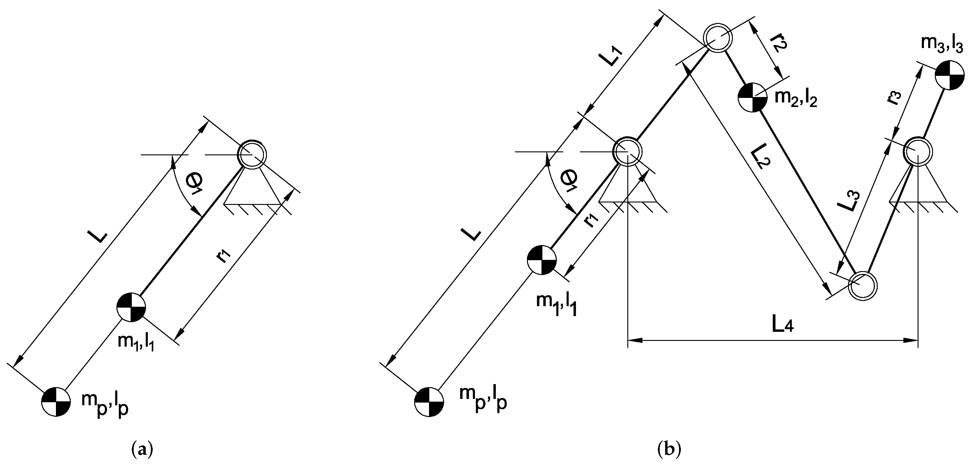
The single rotatable link shown in
Figure 1a can be regarded as the starting point of the structural design and can be considered as the manipulator arm that has been integrated into the inverted four-bar linkage to achieve the dynamically balanced mechanism in
Figure 1b. The unbalanced rotatable link has a length
L, a tip mass
, and a tip inertia
. In both
Figure 1a,b each link has a mass
and an inertia
with the link center of mass (CoM) at a distance
as illustrated, with i the link number. The angle of the link with respect to the horizontal axis is denoted with
. The full length of the first link in
Figure 1b is the sum of length
L of the rotatable link and extension
and the length of the third link is the sum of
and
. The distance between the two base pivots is denoted with
, while the coupler link has a length
. The mechanism is dynamically balanced when Equations (
1) and (
2) [
15] are satisfied and the CoM of each link is located on the centre line of the link as shown in
Figure 1b. As compared to counter rotating flywheel based architectures, in the balanced inverted four-bar linkage link 3 can be regarded a counterrotation with coupler link 2 as the transmission that is stiff and without backlash, a significant advantage of this solution.
Force balance conditions:
Moment balance conditions:
2.2. Mode Shapes of the Balanced Manipulator Arm
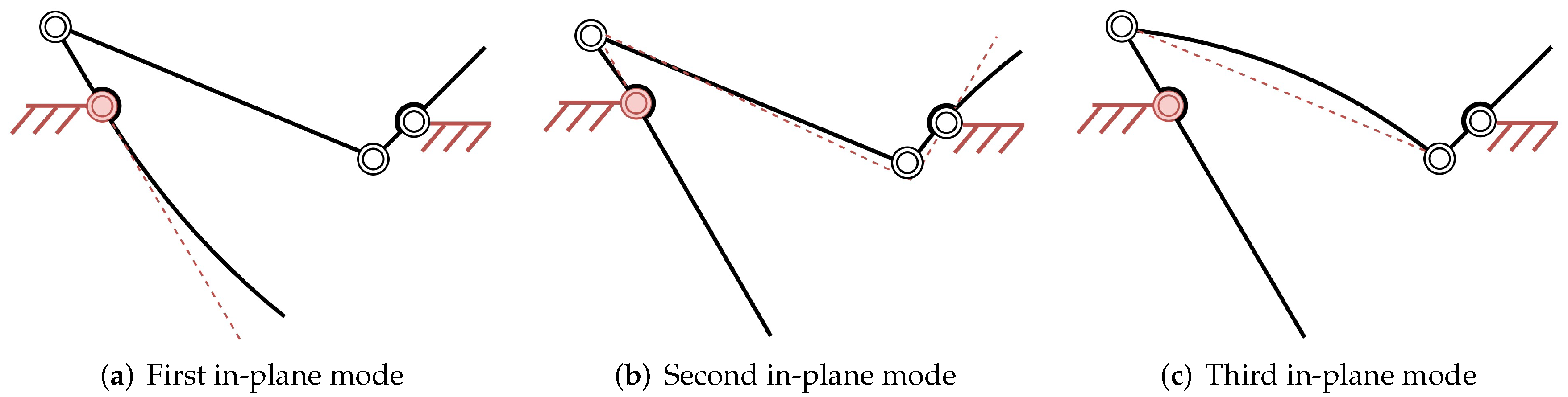
The natural frequencies indicate at which frequencies elements of a mechanism are prone to vibrate, whereas mode shapes show how the mechanism deforms at each natural frequency. The natural frequencies of a design can be increased by adding stiffness or by reducing the mass for which the mode shapes show the locations with significant deformation requiring additional stiffness. The first three distinctive in-plane mode shapes of the mechanism in
Figure 1 are found as shown in
Figure 2. For the modal analysis the actuation is located in the base pivot of the first link and is assumed rigid as indicated in red.
The three mode-shapes in
Figure 2 were determined with the help of Spacar [
17], which is a numerical flexible multi-body software package based on the Euler Bernoulli beam theory. The first mode shown in
Figure 2a is predominantly caused by the tip mass
in combination with the relatively low lateral stiffness of the first link. The second mode shape in
Figure 2b is mainly the result of the elasticity in link 1 and 3, combined with the as balancing mass acting mass of link 3. The third mode shape in
Figure 2c is mainly depending on the elasticity of link 2 combined with its mass distribution. To increase the stiffness of these links, without changing the material, link lengths can be reduced or the second moment of area could be increased. The cross-section and link length therefore need to be taken into account in order to optimize natural frequencies. It needs to be noted that although reducing the length of the links increases stiffness, it comes at the cost of additional mass to satisfy the balance equations. The natural frequency associated with the second in-plane mode shape depends also on the position of the mechanism. When
is larger than
the excitation of the second mode shape loads link 1 and link 3 predominantly longitudinally. For smaller angles these links are loaded predominantly transversely, for which they have a lower stiffness resulting in lower natural frequencies.
3. Structural Design
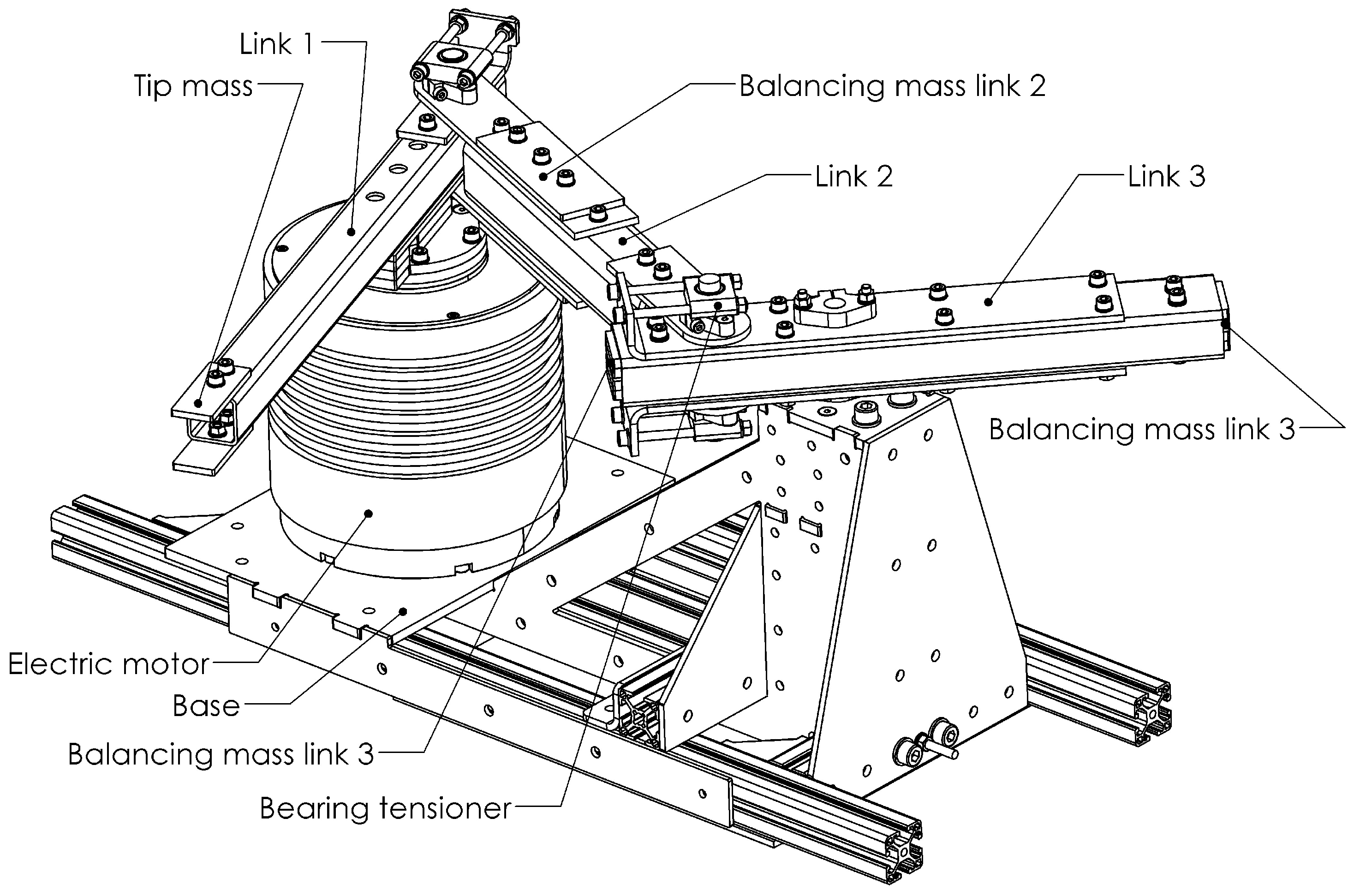
The structural design of the prototype dynamically balanced manipulator arm is presented in
Figure 3. All revolute joints consist of plain bearings, except for the ETEL RTMBi140-100 direct drive motor which has two ball bearings. Since the balls in a ball bearing have an angular velocity different from the links and therefore a deviating angular momentum, they could affect the moment balance quality, which is not the case for plain bearings. The plain bearings were assembled with two bearing tensioners, one on each side of the link. These bearing tensioners are an additional set of plain bearings which are tensioned in order to remove play, therefore preventing another source of vibrations. Since the friction forces in the joints result solely in internal forces, they do not affect the overall balance quality.
3.1. Design Details
All links were made of stainless steel tubes of which the dimensions are listed in
Table 1. Additional balancing masses
and twice
for tuning the mass distribution and also the bearing mountings were made from stainless steel sheet metal. The axles of link 2, the coupler link, and the axle mounts were all made from aluminium. The axle of the base pivot of link 3 was made from steel for a higher strength.
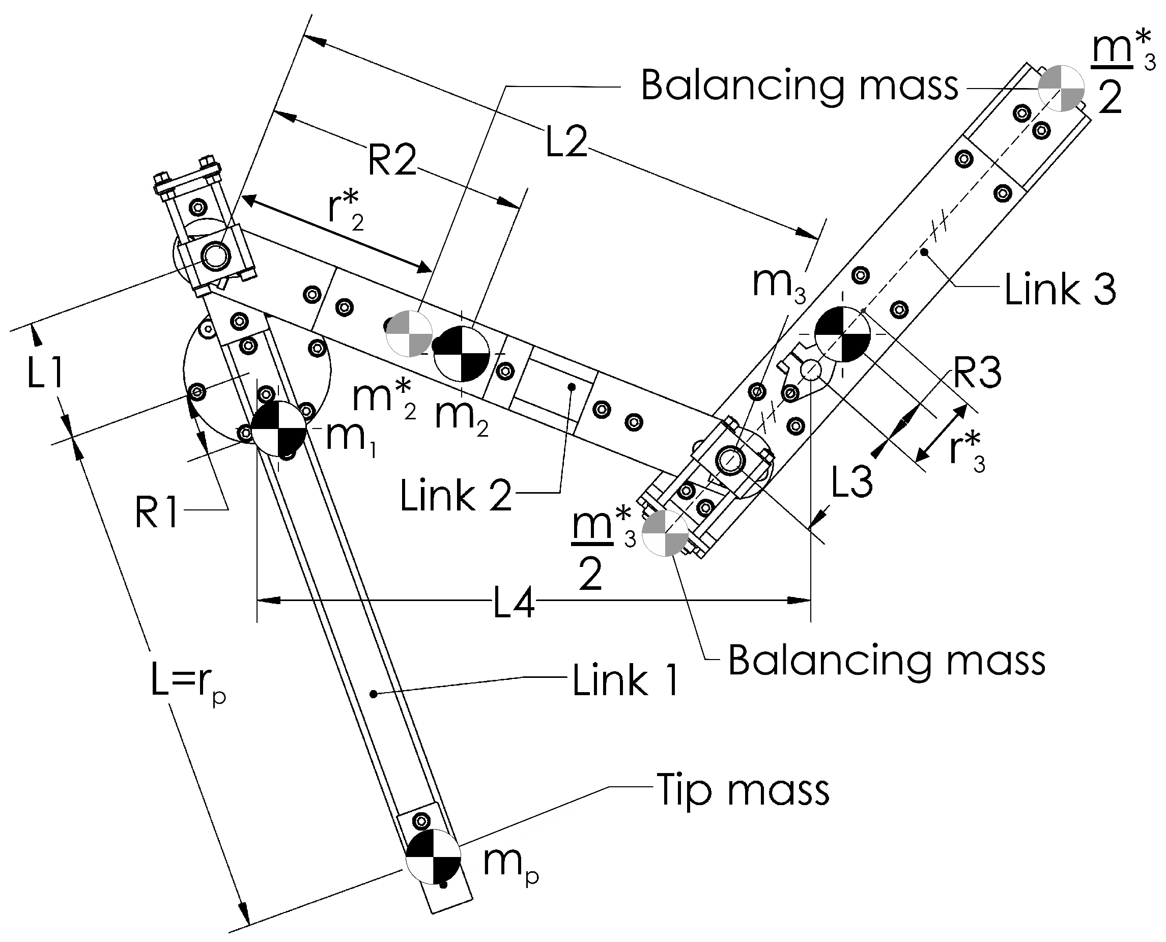
A top view of the balanced mechanism with its geometric design parameters is shown in
Figure 4 and the inertial and geometric parameter values have been listed in
Table 2. In this table link parameters
,
, and
include all masses and inertias of the link i and the tip mass, including the values for
and
and for the actuator inertia. The parameters related to the individual balancing masses
and
are denoted with an asterisk and the inertia of each link is taken at the link CoM. The admissible range of motion of the mechanism is from
deg to
deg.
The values in
Table 2 have been found by an iterative design process based on three steps: (1) Initial parameter optimization with Spacar, (2) detailed computer aided design (CAD), and (3) verification of natural frequencies.
The starting point in the design was the initial unbalanced mechanism in
Figure 1a with a tip mass (
) of 112.12 g connected to the actuator with a link length
m. The initial lengths of
,
,
, and
were determined before the detailed design by a genetic algorithm in combination with Spacar. Since incorporating the unbalanced manipulator arm in the balanced four-bar mechanism introduces additional natural frequencies, for optimal dynamic performance these frequencies need to be higher than the first natural frequency of the manipulator arm itself. Since for analysis the base pivot of link 1 is fixed, the first natural frequency of the balanced manipulator arm is equal to the unbalanced arm. The goal of this optimization therefore is to maximize the second natural frequency of the balanced mechanism. Constraints were considered for the cross-section of the links to keep the tubes rectangular and the lengths of the tubes were constrained to keep the design manufacturable. The mass and inertia of the balancing masses and of the joints were added to the model, while no constraints were applied to the dimensions of the balancing masses. The optimization resulted in an initial length for
,
,
, and
of 78 mm, 310 mm, 78 mm, and 310 mm, respectively, for which the second natural frequency of the mechanism resulted in 565 Hz and is associated with the second in-plane mode shape as shown in
Figure 2b. This frequency can be assumed to the theoretical optimum of the design.
The CAD design requires to take dimensional constraints into account. Therefore the final parameter values in
Table 2 are a trade off between natural frequencies, balance conditions, dimensional constraints, and mass. By satisfying the balance conditions of the second link and the resulting dependency among mass, inertia, and CoM, it was required to shorten the length of
to 70 mm.
In order to reduce the mass of the third link (), it follows from the balance conditions that the inertia () of the link needs to be increased. Therefore link 3 includes the two balance masses which are located at the extremities of the link with their common CoM at a distance from the base pivot. This construction reduces the total mass of the third link by 36% as compared to having a single balance mass. In addition, the second in-plane natural frequency increases by 5%.
3.2. Finite Elements Simulation
The natural frequencies of the CAD model were analysed with Comsol [
18]. The analysis did not take the stiffness of the bolted connections into account in order to reduce the computational effort. The axles and the bearing tensioners were added in the simulation as point masses. To omit internal collisions of the links during frequency sweeps, it was chosen to perform the analysis around the centre of the admissible motion range at
deg. The three identified mode shapes of
Figure 2 are clearly recognizable in the simulation results shown in
Figure 5.
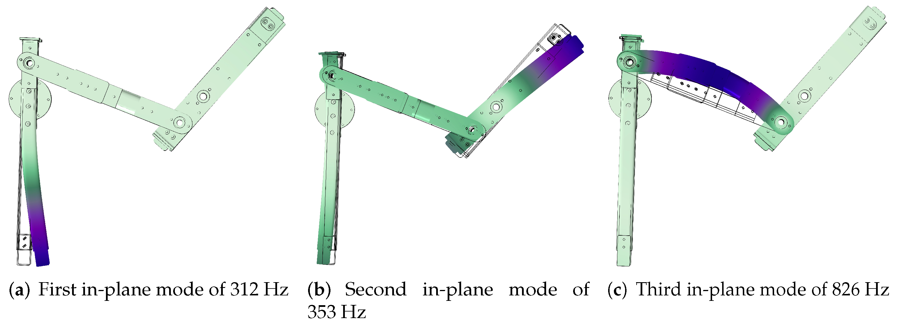
The first natural frequency of 312 Hz in
Figure 5a is located in the manipulator arm and therefore equal to the unbalanced rotatable arm in
Figure 1a. Of the second and third natural frequencies in
Figure 5b,c, respectively, the latter is significantly higher. The natural frequency of the second in-plane mode shape depends significantly on the stiffness along the length
. For a construction based on tubes, a high stiffness, however, is challenging to obtain.
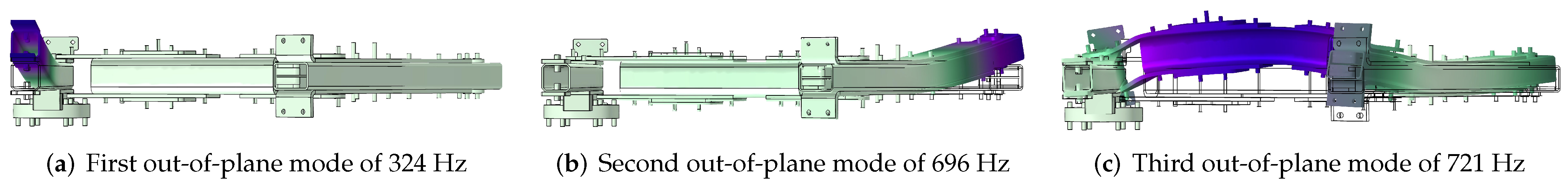
In addition to the in-plane modes shapes, three out-of-plane modes were observed. The first out-of-plane mode shown in
Figure 6a affects link 1 and is equal for both the unbalanced rotatable link in
Figure 1a as for the same link in the balanced design in
Figure 1b. The second mode shown in
Figure 6b is a result of the balancing mass added at the end of the third link. The excitation of this mode is limited, since the fluctuating forces in this direction are insignificant during motion. In contrast, the third out-of-plane mode shape shown in
Figure 6c is easily excited during motion, as this link then is loaded longitudinally. Still, the natural frequency associated with this mode shape is significantly higher than that of the second in-plane mode shape.
By altering the angle
it was confirmed that the natural frequency associated with the second in-plane mode shape is significantly affected by the position of the mechanism. At an angle
deg the frequency is significantly lower with 346 Hz, due to the increased transverse loading in link 1 when this mode is excited. Increasing angle
to 115 degrees results in a natural frequency of 390 Hz, which then is due to an increased longitudinal loading. The natural frequencies of the other mode shapes in
Figure 5 and
Figure 6 are marginally affected by the position of the mechanism.
3.3. Bearing Loads and Actuation Torques
The actuation torque of the dynamically balanced manipulator arm about the base pivot of link 1 is 2.2 times higher than that for the unbalanced rotatable link 1, which is due to the increased reduced inertia of the mechanism. The peak loads in the bearings of the base pivots are 4.2 times higher for the balanced manipulator arm.
4. Robustness and Manufacturing Tolerances
During manufacturing, errors in mass and dimensions occur due to manufacturing and material tolerances. To minimize mass errors all elements were weighed with an accuracy of 0.01 g and physical measurements were incorporated in the CAD model before calculation of the separate balancing masses. The influence on the balance quality of the remaining mass errors in counter-masses, dimensional tolerances in links, and tip mass deviations were studied by simulations in Simulink [
19]. It was assumed that the mass distribution and radius of gyration were not affected by the mass errors, which makes mass and inertia errors linearly dependent. The balance quality is defined as a percentage where 100% corresponds to a perfectly dynamically balanced mechanism and 0% corresponds to the unbalanced single rotatable link 1. The parameter values of the unbalanced mechanism, including the actuator, are shown in
Table 3. For this analysis the mechanism was assumed rigid and an ODE45 solver was used. The force balance quality was determined by the in-plane peak reaction force, calculated with max(
). The moment balance quality was determined by max(
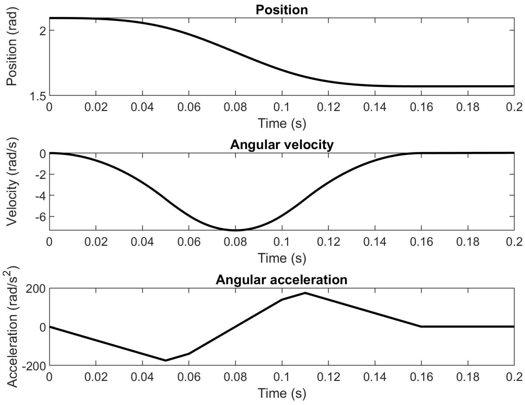
). The reference trajectory was based on the S-curve motion profile shown in
Figure 7.
4.1. Mass Errors
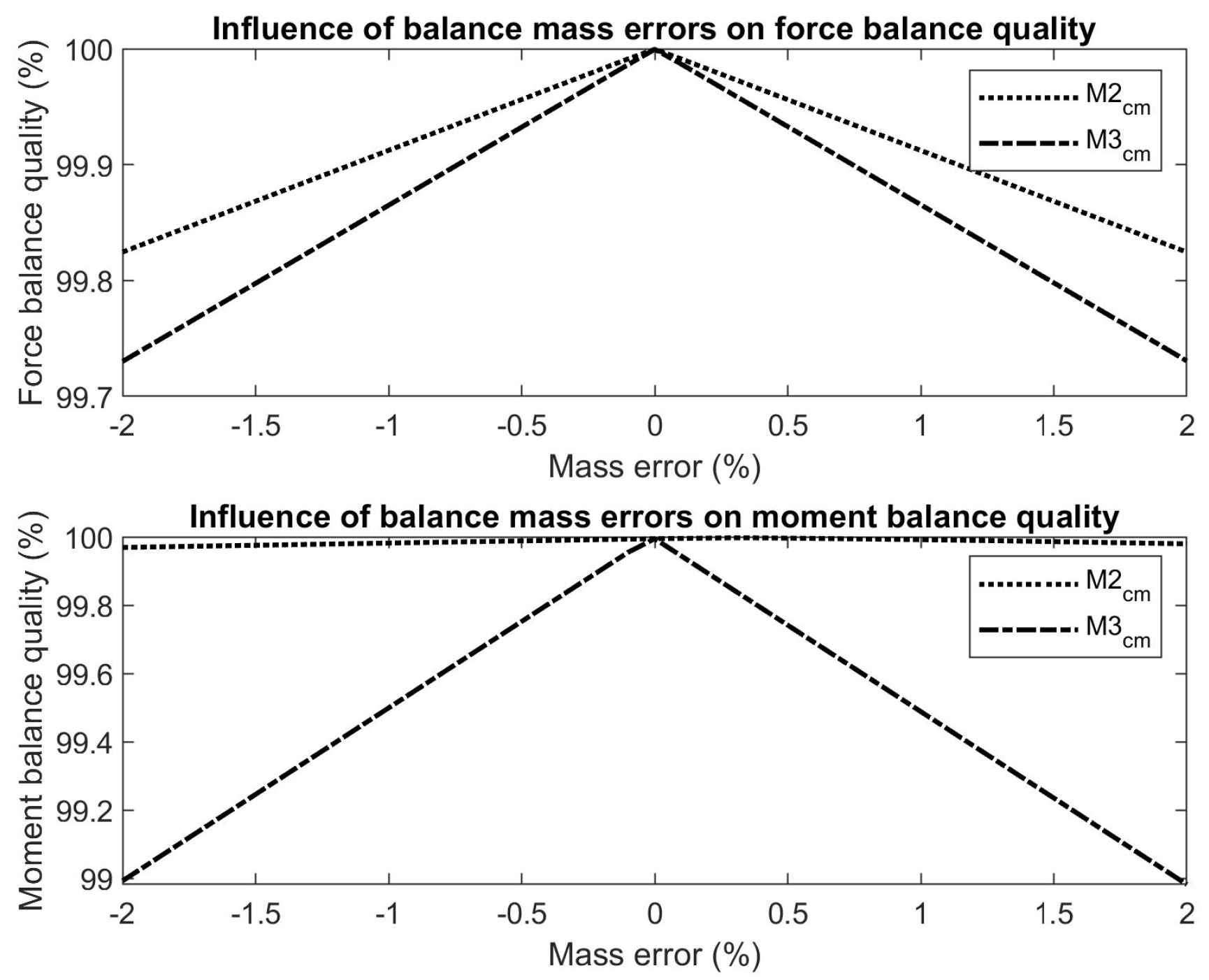
The influence of mass errors in the balance masses on both the force and moment balance quality is shown in
Figure 8. It reveals that the performance is significantly more sensitive to mass errors in the third link than of mass errors in the second link. The impact of mass errors in the balance masses of the second link could still be further reduced by taking these errors into account during the calculation of the balance masses of the third link. This is possible since the force balance condition of the third link, Equation (
1), can be addressed after link 2 has been completed, which was not done here.
For moment balance the angular momentum of the complete mechanism must be constant [
6], which depends on the inertia and the angular velocity of each link [
20]. Due to the higher angular velocity and inertia of the third link as compared to the second link and therefore the larger contribution of link 3 to the moment balance, mass errors in the third link have a significantly larger impact on the moment balance quality.
The balance masses were produced by laser cutting where multiple test pieces averaged a raw mass error of 0.61%. With the help of post processing these errors could possibly be further reduced.
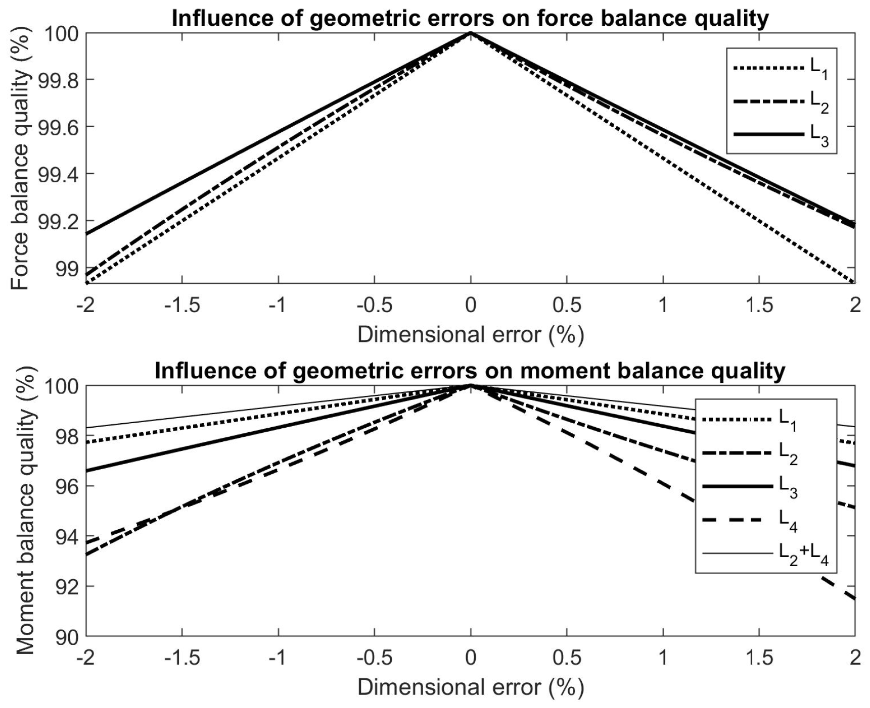
4.2. Geometry Errors
Figure 9 shows the influence of link length deviations on the balance quality, revealing that the force balance quality is most sensitive to deviations of
, while the moment balance quality is most sensitive to deviations of
. Deviations in length
not only affect the moment balance, but also alter the torque arm between the two base joints, with significant impact on the moment balance quality. Sensitivity to deviations of
and
are significantly lower when those lengths remain equal to each other.
The length deviations due to the production tolerances were estimated to be below 0.1 mm. By the tensioning devices removing play in the plain bearings, deviations of up to 0.05 mm in each bearing can occur. Therefore in total the dimensional deviations could be up to 0.2 mm. Within these tolerances it was calculated that the force balance quality remains above 99% and the moment balance quality remains above 98%.
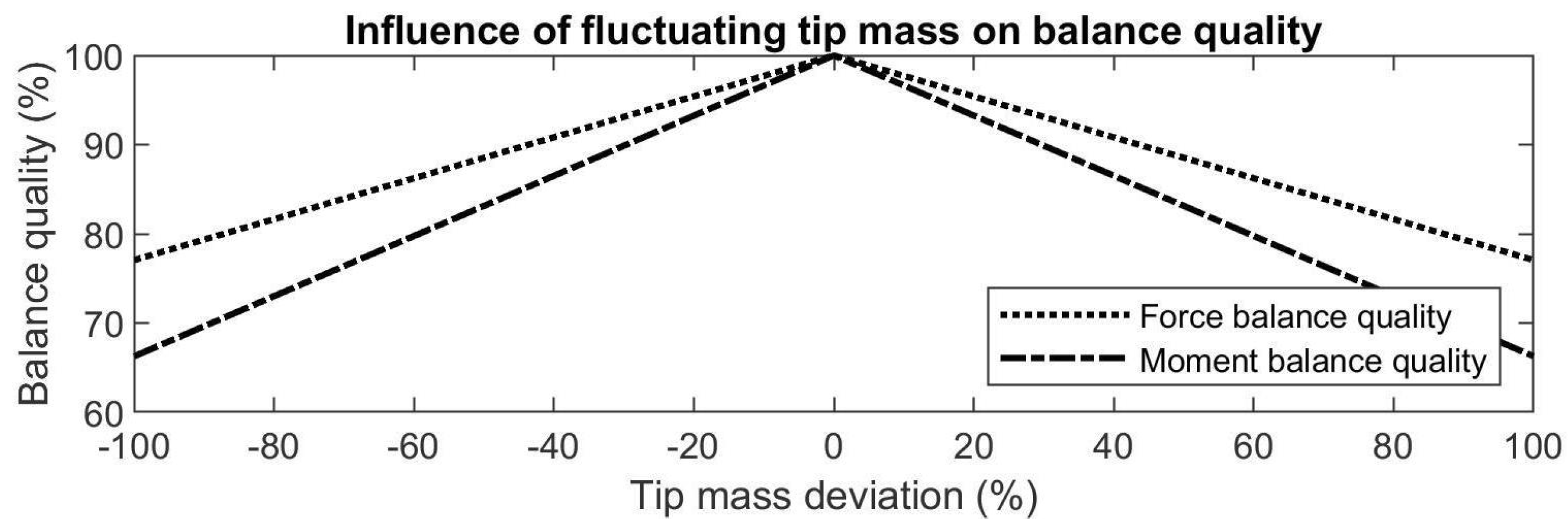
4.3. Fluctuating Tip Mass
When the tip mass
would be regarded a payload, for example in pick-and-place applications, then this mass would vary significantly for each cycle.
Figure 10 shows that when the tip mass is completely removed, the force balance quality has reduced to 75% while the moment balance quality has reduced to 65%. This means that deviation of the tip mass has a significant influence, which, however, remains relatively low for small deviations.
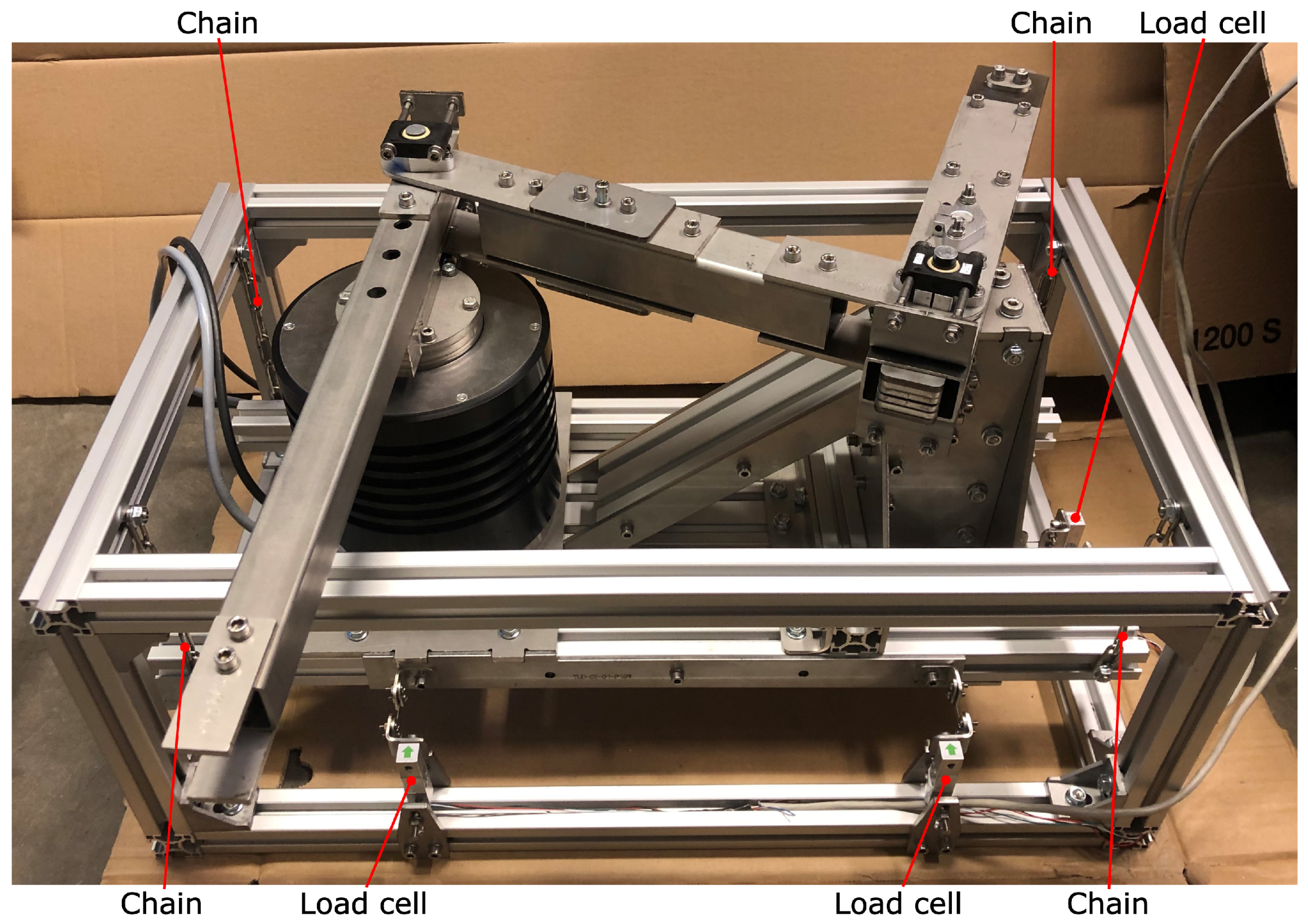
5. Experimental Setup
A prototype of the dynamically balanced manipulator arm was fabricated in an experimental setup, which is shown in
Figure 11. The base consists of aluminium extrusion profiles with stainless steel plates. To allow for small movements of the base for measurements within the horizontal plane, the base is suspended by four chains from an external aluminium frame. For measuring the reaction forces and the reaction moment within the horizontal plane, three single point loads-cells were installed as indicated with numerical balloons in
Figure 12. Each of the load cells could measure a maximum force of 49 N with a precision of 0.05%. Load cell 1 measured the forces along the X-axis, while load cells 2 and 3 measured the forces along the Y-axis. From load cells 2 and 3 the in-plane shaking moment about the Z-axis was calculated by multiplying the measured force at load cell 3 with the distance between load cells 2 and 3. To minimize any parasitic forces in transverse directions, the connections between the load cells and the base were made of thin flexible rods of steel as shown in detail A in
Figure 12. The rod connected to load cell 1 has a diameter of 1 mm, while the rods connected to load cells 2 and 3 have a diameter of 0.5 mm. Each load cell was electronically connected to a Penko SGM 720 load cell transducer, which sampled each load cell at a frequency of 1 kHz. In order to determine the balance quality and to compare the performance with the theoretical model, the reaction forces and the reaction moment were measured for the mechanism moving with the trajectory of
Figure 7.
The manipulator arm was actuated by an ETEL RTMBi140-100 direct drive motor, which can deliver a peak torque of 131 Nm. The trajectory was achieved by feedback control only, in which the PID control was automatically tuned by the ETEL motion controller. The natural frequencies of the manipulator arm were determined with a frequency sweep conducted by the same ETEL motion controller. Videos of the manipulator in action are available as
Supplementary Material.
6. Experiments and Experimental Results
Four experimental evaluations were performed with the experimental setup: (1) The balance quality when dynamically balanced, (2) the balance quality with reduced tip mass (i.e., when partly balanced), (3) identification of the natural frequencies, and (4) the maximal acceleration capabilities of the prototype. The balance quality of the mechanism was determined similarly as in
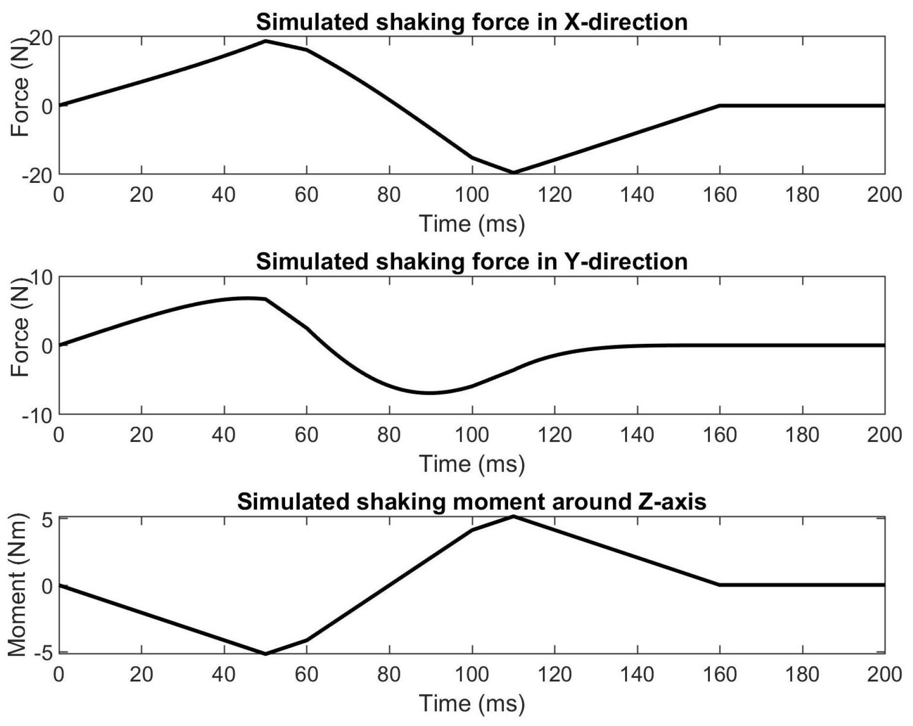
Section 4. The simulated unbalanced rotatable link 1 was chosen as the reference to keep results between the simulations and the experiments comparable. The shaking forces and shaking moment exerted on the base by the simulated unbalanced manipulator arm for the trajectory in
Figure 7 are shown in
Figure 13. The reaction force in this figure is the magnitude of the reaction force vector in the horizontal plane. In these simulations the mass and inertia of all components of the real prototype were taken into account. The motion consisted of a rotation of 30 degrees within 160 ms. During this motion a peak rotational acceleration was reached of 174.5 rad/s
2, meaning that the point of the tip mass reached a transverse acceleration of 51.1 m/s
2 or 5.2 G.
6.1. Balance Quality When Dynamically Balanced
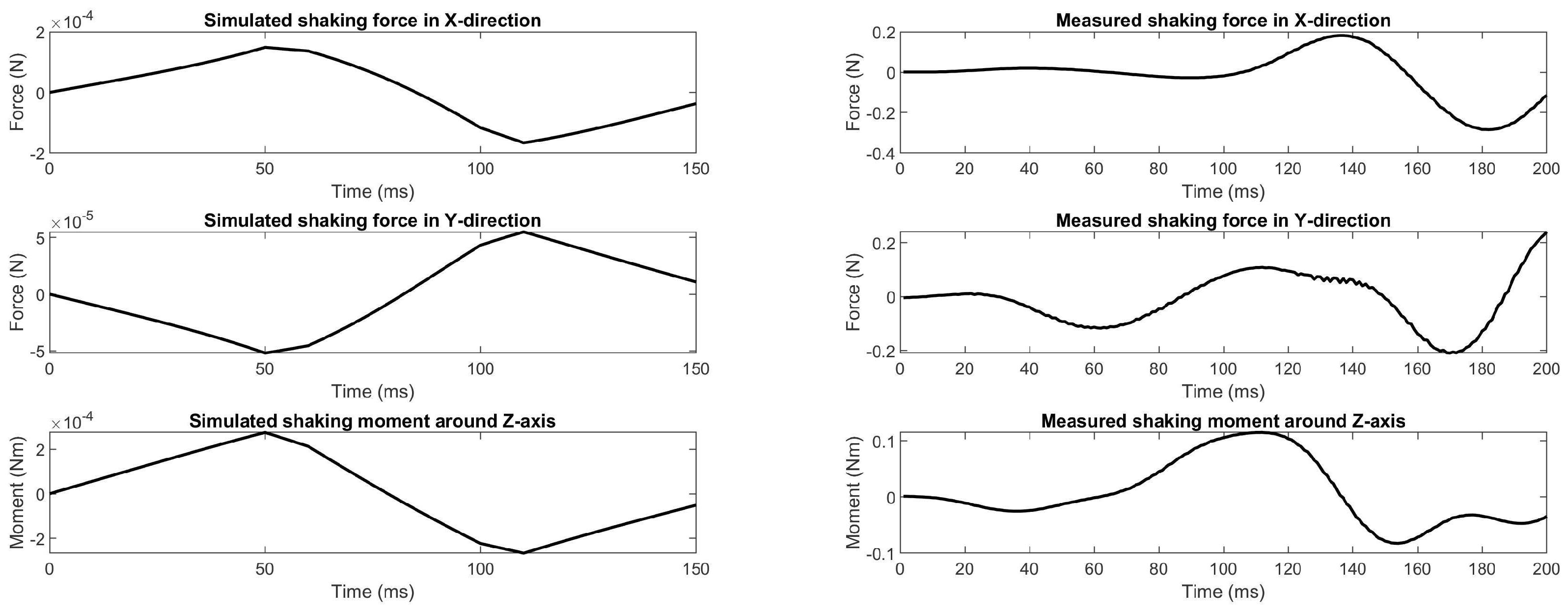
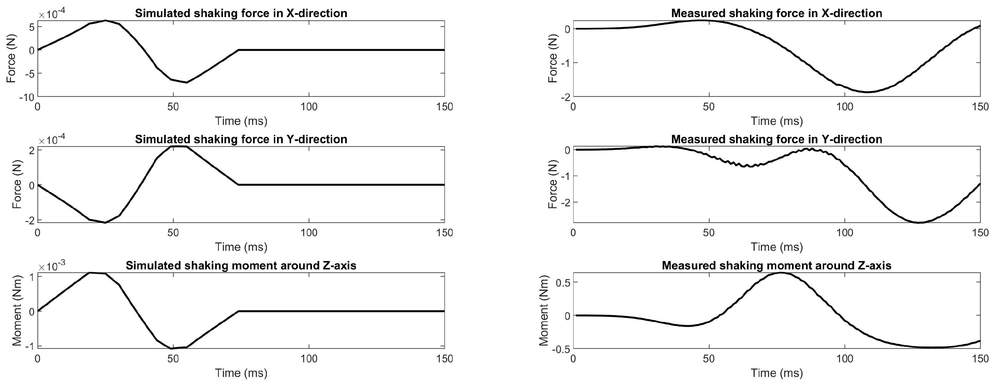
Figure 14 shows the shaking forces and the shaking moment exerted to the base of the prototype from simulations (including the manufacturing errors) and from measurements with the experimental setup. Comparing the simulations with the measurements reveals that the measured shaking forces and shaking moment are significantly higher than from the simulations. The measured results are smoother than the results from simulation due to damping. Based on the measurements, the force balance and moment balance quality during motion results in 99.3% and 97.8%, respectively. The moment balance quality is slightly lower than expected, which could have been caused by a deviation in the reported motor inertia of the manufacturer and by the third link which turned out not being perfectly straight but slightly curved and without perfect rectangular cross-section, which was not taking into account in the simulations.
6.2. Balance Quality with Reduced Tip Mass
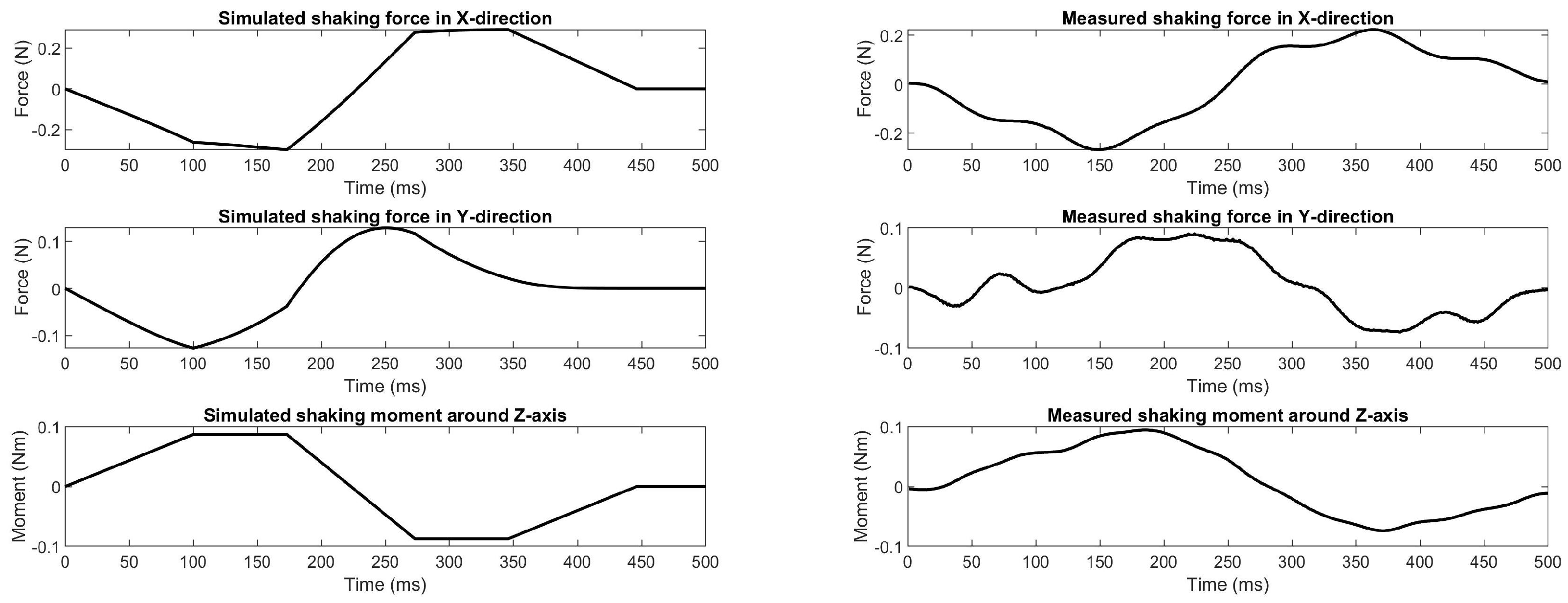
The balance quality for a reduced tip mass was measured with a 50% lower mass
of 56.06 g of which the results are shown
Figure 15. The motion trajectory was the same as in the previous experiment, however with 90% lower accelerations and a peak tip acceleration of 0.52 G since for peak accelerations of 5.2 G the deformations of the load cells and the connecting rods due to the shaking forces and shaking moment caused unreliable measurements.
It is observed in
Figure 15 that the measurements are close to the simulated values. The shaking forces are slightly lower than simulated, which is likely due to a combination of the transverse stiffness of the connection rods and vibrations caused by the unbalance in the measurement setup. By comparing the measurements of
Figure 15 with
Figure 14, then it can be observed that the shaking forces and shaking moment have clearly increased. With half of the tip mass, the measured force and moment balance quality are 90.3% and 81.9%, respectively, which is higher than the predicted values of 85.3% and 83.12%, respectively.
6.3. Identification of the Natural Frequencies
A frequency sweep was conducted to determine the natural frequencies of the prototype in the experimental setup. The sweep was done in the position
deg, which is approximately in the centre of the range of motion.
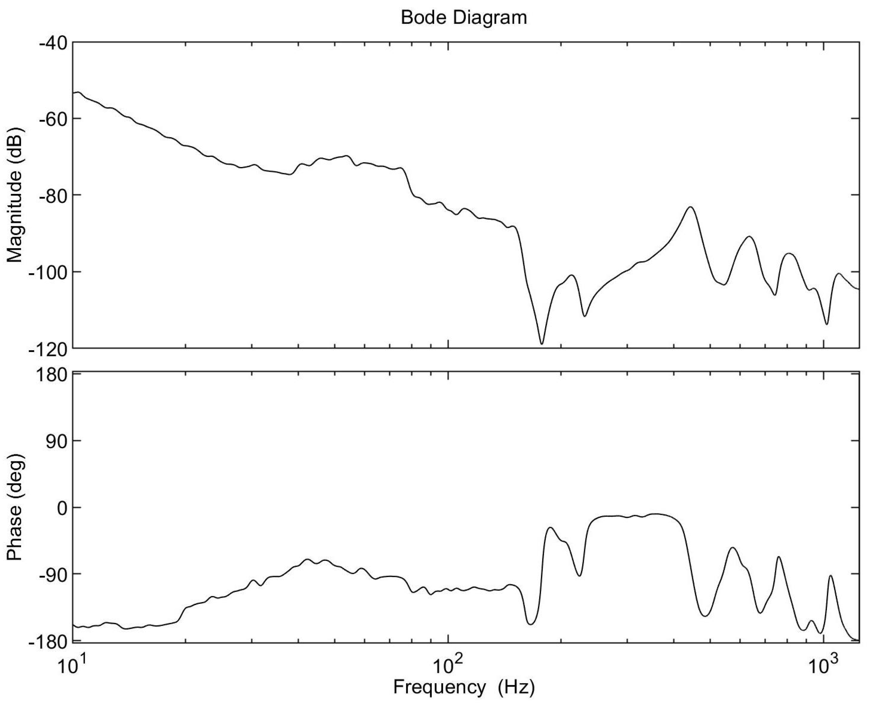
Table 4 shows the results of the frequency sweep and of the FEA simulations. A bode plot of the frequency sweep can be found in
Figure A1.
The results in
Table 4 show that the first measured frequency is 32% lower than obtained from the FEA. The main reason for this deviation is caused by the relatively high elasticity of the base, which was assumed rigid in the FEA simulation. This is supported by earlier experiments that were carried out with a base design with fewer structural members, resulting in even more elasticity with a 55% lower first natural frequency that was measured. This means that the stiffness between the two base pivots have a significant influence on the natural frequencies of the mechanism. Moreover, the bolted connection between the actuator and first link, which was modelled rigidly in the simulations, is expected to have resulted in the lower measured frequencies.
6.4. Maximal Acceleration Capabilities of the Prototype
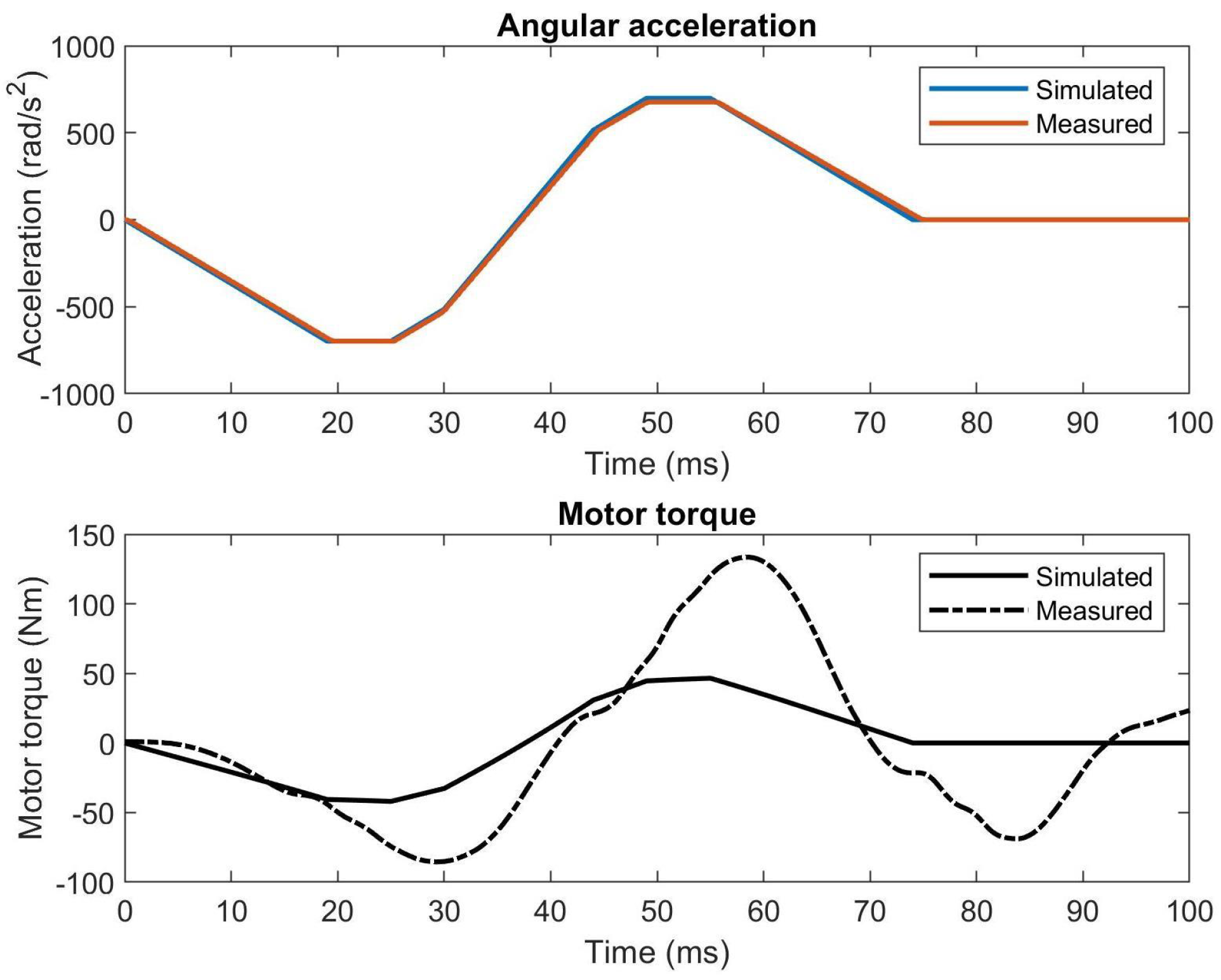
Finally, the maximal tip accelerations of the experimental setup were investigated, resulting in tip accelerations of over 21 G. Since the ETEL motion controller could not directly measure the angular accelerations during motion, they were derived from the measured angular velocity by central finite difference. The motor torque was calculated from the measured motor current with a motor torque constant of 4.264 Nm/A. Both the angular accelerations and the motor torque are shown for comparison with the simulations in
Figure 16.
As can be seen in
Figure 16, the measured angular acceleration is about equal to the simulation, confirming that the tip has successfully reached a transverse tip acceleration of over 21 G (21.35 G precisely). While the simulations predicted a peak actuation torque of 46.7 Nm, a peak of 133.2 Nm was measured during experiments. This is expected to be caused by the poor PID controller and also by joint friction, which were not considered in the simulations. This means that the prototype still has potential to move significantly faster after optimizing the PID-controller and after implementing feed-forward control. The actuation torque shows to not be instantly zero after the motion is finished, which is caused by the PID controller that is still controlling the damping to reach the final position.
Figure 17 shows the measured shaking forces and shaking moment for 21 G tip accelerations, which turn out to increase significantly after the motion was finished after 75 ms. This increase could have been caused by rotational motion about the z-axis of the base within the experimental setup as a result of a higher shaking moment. The high actuation torques could also have resulted in elastic deformations of the manipulator links for which the manipulator becomes slightly unbalanced, increasing the shaking moment. The measured values show a force balance quality and a moment balance quality of 97.2% and 96.9%, respectively. These values are slightly lower than the measured values for accelerations up to 5 G.
7. Discussion
This paper presented the structural design and the experimental verification of a dynamically balanced inverted four-bar mechanism, aimed at high acceleration robotic manipulator applications. The main focus in the design was on optimizing the natural frequencies with the help of the mode shapes. The significance of each mode shape, however, was not taken into account. Analysis including the mode participation factors could gain insight in the contribution of each mode to the dynamic response when actuated in a particular direction [
21]. The bode plot of the manipulator arm in
Figure A1 reveals that the second resonance peak (at 443 Hz) is higher than the first peak (at 212 Hz), meaning that it is the second peak that is limiting the controller performance here. By moving the amplitude of the second resonance peak below the amplitude of the first resonance peak would increase the controller performance significantly.
The experimental setup showed a first natural frequency of 212 Hz and it successfully performed a motion with a peak transverse tip acceleration of about 21 G. While significant improvement of the prototype manipulator is still possible, cycle times of around 200 ms are within reach of the current design for this motion, resulting in cycle rates of around five cycles/second with a motion distance of 7.8 cm. The measured natural frequencies of the prototype therefore are already sufficiently high for realistic implementation in high acceleration applications.
The use of stainless steel tubes and sheet metal limited the design and the dimensional tolerances of the prototype and resulted in a reduction of the balance quality. Perhaps producing the links more precisely by CNC milling of a (topology) optimized design could result in significantly higher natural frequencies [
22]. The objective of the topology optimization then should be the maximization of the natural frequencies with the balance conditions added as constraints of the optimization.
In
Figure 14,
Figure 15 and
Figure 17 a vibration with a frequency of 18.18 Hz is noticeable in the shaking moment measurements. This vibration was caused by the low transverse stiffness of the connecting rods between the load cells and the base in combination with the high inertia of the base, mechanism and actuator. Adding stiffness to these connecting rods would lower the vibrational amplitude, but would also cause measurement errors due to higher transverse loading of the load cells. Comparable issues have been reported with a measurement setup based on a multi DoF force measurement sensor [
11].
The tensioning devices removed the play in the plain bearings; however, it was challenging to tune them well. Tensioning the bearings too much caused a large integral term in the PID controller due to high friction and both the integral term and the friction caused significantly higher actuation torques and settle times. Reducing the tension in the bearings improved the PID controller performance, but it increased the backlash in the joints. A solution for finding an optimum between the two would be by extending the PID controller with feedforward control. With the help of feedforward control the PID can be tuned for error rejection, which would result in fewer actuator saturation. The calculation of the feedforward torques then also would require a real time operating system which communicates with the ETEL control system.
Pick-and-place applications often require multi-DoF manipulators, whereas this study focussed on a single DoF manipulator only. Future work therefore is needed to investigate how the theory of the balanced inverted four-bar linkage can be effectively extended to multi-DoF applications to obtain designs of dynamically balanced multi-DoF manipulators with short settling time.
8. Conclusions
In this paper the structural design of a manipulator arm with high natural frequencies that is based on a dynamically balanced inverted four-bar linkage was presented and experimentally verified. The dynamic properties of the manipulator arm were evaluated by analysing the first three in-plane natural frequencies, showing that the transverse stiffness of the first link, the manipulator arm, and the second link, the coupler link, have most influence on the natural frequencies. For the robustness to manufacturing tolerances it was shown that the manipulator is more prone to geometric deviations than to deviations of mass.
A prototype manipulator in an experimental setup was built to verify both the dynamic balance and the dynamic properties. The prototype successfully performed high acceleration motions with minimal shaking forces and shaking moment. When compared to the unbalanced case, a reduction of 99.3% in shaking forces and 97.8% in shaking moment was measured for end-effector accelerations of 5.2 G. For the partly balanced case with only half of the required end-effector mass, a force and moment balance quality was achieved of 90.3% and 81.9%, respectively. While these values are lower than for the fully balanced case, the shaking forces and shaking moment are still significantly lower than for the unbalanced case. A first natural frequency of 212 Hz was measured, which is significantly lower than the 312 Hz obtained from simulations, which is primarily caused by the lower stiffness of the base design. While significant improvement of the prototype manipulator is still possible, the natural frequencies are already sufficiently high to achieve short settling times and short cycle times during high-speed motions.
The experimental setup achieved end-effector accelerations of 21 G. Since the prototype was fabricated with relatively basic production methods, it shows that it is relatively simple to manufacture a dynamically balanced manipulator suitable for high acceleration applications.
Author Contributions
Conceptualization, M.J.J.Z. and V.v.d.W.; methodology, M.J.J.Z.; software, M.J.J.Z.; validation, M.J.J.Z. and V.v.d.W.; formal analysis, M.J.J.Z.; investigation, M.J.J.Z.; resources, M.J.J.Z. and V.v.d.W.; data curation, M.J.J.Z.; writing—original draft preparation, M.J.J.Z.; writing—review and editing, M.J.J.Z. and V.v.d.W.; visualization, M.J.J.Z.; supervision, V.v.d.W.; project administration, V.v.d.W. All authors have read and agreed to the published version of the manuscript.
Funding
This research received no external funding.
Institutional Review Board Statement
Not applicable.
Informed Consent Statement
Not applicable.
Data Availability Statement
Not applicable.
Conflicts of Interest
The authors declare no conflict of interest.
Appendix A. Frequency Response of the Prototype
Figure A1.
Bode plot of the balanced prototype with motor torque as input and rotary position as output.
Figure A1.
Bode plot of the balanced prototype with motor torque as input and rotary position as output.
References
- Germain, C.; Caro, S.; Briot, S.; Wenger, P. Optimal design of the IRSBot-2 based on an optimized test trajectory. In Proceedings of the ASME 2013 International Design Engineering Technical Conferences and Computers and Information in Engineering Conference, Portland, OR, USA, 4–7 August 2013. [Google Scholar]
- Briot, S.; Pashkevich, A.; Chablat, D. On the optimal design of parallel robots taking into account their deformations and natural frequencies. In Proceedings of the ASME 2009 International Design Engineering Technical Conferences and Computers and Information in Engineering Conference, San Diego, CA, USA, 3 August–2 September 2009. [Google Scholar]
- Pierrot, F.; Baradat, C.; Nabat, V.; Company, O.; Krut, S.; Gouttefarde, M. Above 40g acceleration for pick-and-place with a new 2-dof PKM. IEEE Int. Conf. Robot. Autom. 2009, 2, 1794–1800. [Google Scholar] [CrossRef]
- Arakelian, V. Inertia forces and moments balancing in robot manipulators: A review. Adv. Robot. 2017, 31, 717–726. [Google Scholar] [CrossRef]
- van der Wijk, V. Methodology for Analysis and Synthesis of Inherently Force and Moment-Balanced Mechanisms: Theory and Applications. Ph.D. Thesis, University of Twente, Enschede, The Netherlands, 2014. [Google Scholar] [CrossRef] [Green Version]
- van der Wijk, V.; Herder, J.L.; Demeulenaere, B. Comparison of various dynamic balancing principles regarding additional mass and additional inertia. J. Mech. Robot. 2009, 1, 1–9. [Google Scholar] [CrossRef] [Green Version]
- De Jong, J.J.; Schaars, B.E.M.; Brouwer, D.M. The influence of flexibility on the force balance quality: A frequency domain approach. In Proceedings of the 19th International Conference of the European Society for Precision Engineering and Nanotechnology, Bilbao, Spain, 3–7 June 2019; Volume 19, pp. 2–5. [Google Scholar]
- Foucault, S.; Gosselin, C.M. Synthesis, design, and prototyping of a planar three degree-of-freedom reactionless parallel mechanism. J. Mech. Des. Trans. ASME 2004, 126, 992–999. [Google Scholar] [CrossRef]
- Laliberté, T.; Gosselin, C. Synthesis, optimization and experimental validation of reactionless two-DOF parallel mechanisms using counter-mechanisms. Meccanica 2016, 51, 3211–3225. [Google Scholar] [CrossRef]
- de Jong, J.; van Dijk, J.; Herder, J. A screw based methodology for instantaneous dynamic balance. Mech. Mach. Theory 2019, 141, 267–282. [Google Scholar] [CrossRef]
- van der Wijk, V.; Krut, S.; Pierrot, F.; Herder, J.L. Design and experimental evaluation of a dynamically balanced redundant planar 4-RRR parallel manipulator. Int. J. Robot. Res. 2013, 32, 744–759. [Google Scholar] [CrossRef]
- Karidis, J.; McVicker, G.; Pawletko, J.; Zai, L.; Goldowsky, M.; Brown, R.; Comulada, R. The Hummingbird minipositioner-providing three-axis motion at 50 g’s with low reactions. In Proceedings of the 1992 IEEE International Conference on Robotics and Automation, Nice, France, 12–14 May 1992; Volume 1, pp. 685–692. [Google Scholar] [CrossRef]
- Menschaar, H.F.; Ariens, A.B.; Herder, J.L.; Bakker, B.M. Five-Bar Mechanism with Dynamic Balancing Means and Method for Dynamically Balancing a Five-Bar Mechanism. WIPO WO2006080846A1, 3 August 2006. [Google Scholar]
- Raaijmakers, R. Besi zoekt snelheidslimiet pakken en plaatsen op (besi attacks the speedlimit for pick and place motion). Mechatronica Nieuws 2007, 26–31. (In Dutch) [Google Scholar]
- Ricard, R.; Gosselin, C.M. On the Development of Reactionless Parallel Manipulators. In Proceedings of the ASME 2000 Design Engineering Technical Conferences and Computers and Information in Engineering Conference, Baltimore, MD, USA, 10–13 September 2000. [Google Scholar]
- Wu, Y.; Gosselin, C.M. Synthesis of reactionless spatial 3-DoF and 6-DoF mechanisms without separate counter-rotations. Int. J. Robot. Res. 2004, 23, 625–642. [Google Scholar] [CrossRef]
- Jonker, J.B.; Meijaard, J.P. SPACAR — Computer Program for Dynamic Analysis of Flexible Spatial Mechanisms and Manipulators. In Multibody Systems Handbook; Springer: Berlin/Heidelberg, Germany, 1990; pp. 123–143. [Google Scholar] [CrossRef]
- COMSOL AB. COMSOL Multiphysics® 5.4. Available online: https://www.comsol.com/ (accessed on 13 April 2022).
- Mathworks. Matlab® R2019a Update 9. Available online: https://www.mathworks.com/ (accessed on 13 April 2022).
- Berkof, R.S.; Lowen, G.G. A New Method for Completely Force Balancing Simple Linkages. J. Eng. Ind. 1969, 91, 21–26. [Google Scholar] [CrossRef]
- Park, J.H.; Asada, H. Concurrent design optimization of mechanical structure and control for high speed robots. J. Dyn. Syst. Meas. Control Trans. ASME 1994, 116, 344–356. [Google Scholar] [CrossRef]
- Briot, S.; Goldsztejn, A. Topology optimization of a reactionless four-bar linkage. Mech. Mach. Sci. 2018, 50, 414–421. [Google Scholar] [CrossRef] [Green Version]
Figure 1.
(
a) Unbalanced rotatable link; (
b) Rotatable link as manipulator arm within a dynamically balanced inverted four-bar linkage (adapted from [
15]).
Figure 1.
(
a) Unbalanced rotatable link; (
b) Rotatable link as manipulator arm within a dynamically balanced inverted four-bar linkage (adapted from [
15]).
Figure 2.
In-plane mode shapes of the balanced inverted four-bar mechanism assuming an infinitely stiff actuator in the first base pivot, shown in red.
Figure 2.
In-plane mode shapes of the balanced inverted four-bar mechanism assuming an infinitely stiff actuator in the first base pivot, shown in red.
Figure 3.
Final design of the dynamically balanced manipulator arm link 1 mounted on the electric motor and on the base.
Figure 3.
Final design of the dynamically balanced manipulator arm link 1 mounted on the electric motor and on the base.
Figure 4.
Top view of the dynamically balanced manipulator arm link 1 with the main parameters.
Figure 4.
Top view of the dynamically balanced manipulator arm link 1 with the main parameters.
Figure 5.
First three in-plane mode shapes with their natural frequency from finite element analysis at deg. With dark blue the largest displacements of a specific mode shape are shown. The displacements are strongly amplified.
Figure 5.
First three in-plane mode shapes with their natural frequency from finite element analysis at deg. With dark blue the largest displacements of a specific mode shape are shown. The displacements are strongly amplified.
Figure 6.
The first three out-of-plane mode shapes from finite element analysis at deg. With dark blue the largest displacements due to the excitation of a specific mode shape are shown. The displacements are strongly amplified.
Figure 6.
The first three out-of-plane mode shapes from finite element analysis at deg. With dark blue the largest displacements due to the excitation of a specific mode shape are shown. The displacements are strongly amplified.
Figure 7.
Reference trajectory based on the S-curve profile in which the mechanism is moved from deg to deg with a peak rotational acceleration of 174.5 rad/s2.
Figure 7.
Reference trajectory based on the S-curve profile in which the mechanism is moved from deg to deg with a peak rotational acceleration of 174.5 rad/s2.
Figure 8.
The influence of the mass errors in the balancing masses on the balance quality shows to be relatively small.
Figure 8.
The influence of the mass errors in the balancing masses on the balance quality shows to be relatively small.
Figure 9.
The influence of the geometric deviations on the balance quality shows that geometric error have a significantly larger impact on the moment balance quality than on the force balance quality.
Figure 9.
The influence of the geometric deviations on the balance quality shows that geometric error have a significantly larger impact on the moment balance quality than on the force balance quality.
Figure 10.
The influence of the tip mass on the balance quality shows to be significant.
Figure 10.
The influence of the tip mass on the balance quality shows to be significant.
Figure 11.
Experimental setup of the balanced manipulator arm with its base suspended by chains and mounted to the load cells for measurements of the in-plane shaking forces and shaking moment.
Figure 11.
Experimental setup of the balanced manipulator arm with its base suspended by chains and mounted to the load cells for measurements of the in-plane shaking forces and shaking moment.
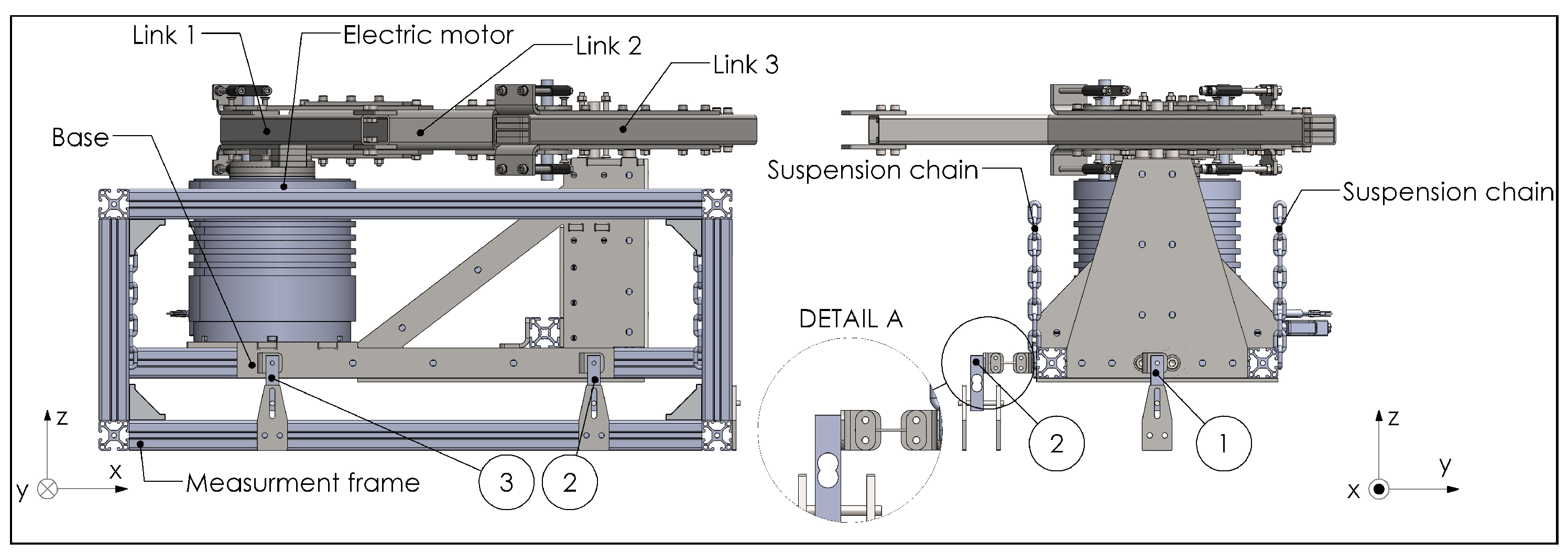
Figure 12.
CAD model of the experimental setup with the manipulator base suspended by chains to allow for small in-plane motions of the base. The numbers denote the positions of the load cells. In the right figure the measurement frame is hidden. Detail A shows the connection of a thin rod between a load cell and the manipulator base.
Figure 13.
Simulated shaking forces and shaking moment of the prototype unbalanced manipulator arm for the motion in
Figure 7. The peak shaking force is 25.54 N and the peak shaking moment is 5.16 Nm.
Figure 13.
Simulated shaking forces and shaking moment of the prototype unbalanced manipulator arm for the motion in
Figure 7. The peak shaking force is 25.54 N and the peak shaking moment is 5.16 Nm.
Figure 14.
Comparison between simulated and measured shaking forces and shaking moment of the balanced mechanism, with a maximal tip acceleration of 5.2 G.
Figure 14.
Comparison between simulated and measured shaking forces and shaking moment of the balanced mechanism, with a maximal tip acceleration of 5.2 G.
Figure 15.
Comparison of the simulated and the measured shaking forces and shaking moment of the balanced manipulator arm with 50% of the tip mass with a maximal tip acceleration of 0.52 G.
Figure 15.
Comparison of the simulated and the measured shaking forces and shaking moment of the balanced manipulator arm with 50% of the tip mass with a maximal tip acceleration of 0.52 G.
Figure 16.
Comparison of the angular acceleration and the motor torque of the measurements and the simulations for a motion with a peak transverse tip acceleration of just over 21 G.
Figure 16.
Comparison of the angular acceleration and the motor torque of the measurements and the simulations for a motion with a peak transverse tip acceleration of just over 21 G.
Figure 17.
Comparison of the simulated and the measured shaking forces and shaking moment of the prototype for a maximal tip acceleration of just over 21 G.
Figure 17.
Comparison of the simulated and the measured shaking forces and shaking moment of the prototype for a maximal tip acceleration of just over 21 G.
Table 1.
Dimensions of the tubes of the links.
Table 1.
Dimensions of the tubes of the links.
| | Link 1 | Link 2 | Link 3 |
|---|
| Width (mm) | 30 | 40 | 50 |
| Height (mm) | 30 | 40 | 30 |
| Wall thickness (mm) | 2 | 4 | 2 |
Table 2.
Parameter values of the balanced manipulator.
Table 2.
Parameter values of the balanced manipulator.
| [mm] | [g] | [mm] | [kgm] |
|---|
| | | | |
| | | |
| | | |
| | | |
| c | | | |
| | | | |
Table 3.
Parameter values of the unbalanced rotatable manipulator including the inertia of the actuator.
Table 3.
Parameter values of the unbalanced rotatable manipulator including the inertia of the actuator.
| [g] | [mm] | [kgm] |
|---|
| | |
Table 4.
Calculated and measured natural frequencies of the balanced manipulator arm for deg.
Table 4.
Calculated and measured natural frequencies of the balanced manipulator arm for deg.
| | | | |
|---|
| FEA | 312 Hz | 721 Hz | 826 Hz |
| Measurements | 212 Hz | 443 Hz | 637 Hz |
| Publisher’s Note: MDPI stays neutral with regard to jurisdictional claims in published maps and institutional affiliations. |
© 2022 by the authors. Licensee MDPI, Basel, Switzerland. This article is an open access article distributed under the terms and conditions of the Creative Commons Attribution (CC BY) license (https://creativecommons.org/licenses/by/4.0/).


