
Design and Characterization of Soft Fabric Omnidirectional Bending Actuators
by
Kyungjoon Lee
1,*,
Khulan Bayarsaikhan
1,†,
Gabriel Aguilar
2,†,
Jonathan Realmuto
1 and
Jun Sheng
1 1
Department of Mechanical Engineering, University of California, Riverside, CA 92521, USA
2
Department of Mathematics, Mt. San Jacinto College, San Jacinto, CA 92583, USA
*
Author to whom correspondence should be addressed.
†
These authors contributed equally to this work.
Actuators 2024, 13(3), 112; https://0-doi-org.brum.beds.ac.uk/10.3390/act13030112
Submission received: 13 February 2024
/
Revised: 2 March 2024
/
Accepted: 11 March 2024
/
Published: 14 March 2024
(This article belongs to the Special Issue Soft Robotics: Actuation, Control, and Application)
Abstract
:Soft robots, inspired by biological adaptability, can excel where rigid robots may falter and offer flexibility and safety for complex, unpredictable environments. In this paper, we present the Omnidirectional Bending Actuator (OBA), a soft robotic actuation module which is fabricated from off-the-shelf materials with easy scalability and consists of three pneumatic chambers. Distinguished by its streamlined manufacturing process, the OBA is capable of bending in all directions with a high force-to-weight ratio, potentially addressing a notable research gap in knit fabric actuators with multi-degree-of-freedom capabilities. We will present the design and fabrication of the OBA, examine its motion and force capabilities, and demonstrate its capability for stiffness modulation and its ability to maintain set configurations under loads. The mass of the entire actuation module is 278 g, with a range of omnidirectional bending up to 90.80°, a maximum tolerable pressure of 862 kPa, and a bending payload (block force) of 10.99 N, resulting in a force-to-weight ratio of 39.53 N/kg. The OBA’s cost-effective and simple fabrication, compact and lightweight structure, and capability to withstand high pressures present it as an attractive actuation primitive for applications demanding efficient and versatile soft robotic solutions.
1. Introduction
The field of soft robotics introduces an alternative to conventional robotics, inspired by the structural flexibility inherent in living organisms. Rigid robots, despite their unparalleled speed and precision in controlled scenarios like manufacturing, face obstacles in unstructured dynamic environments due to their intrinsic rigidity. In contrast, soft robots bring forth a set of attributes tailored to unstructured dynamic environments and thus can potentially address the challenges posed to their rigid counterparts [1,2]. First, the inherent flexibility and compliance of soft robots allow them to interact safely with humans and delicate objects, reducing the risks associated with unexpected collisions or misalignments [3,4,5]. Second, their deformability enables them to operate in complex, unstructured environments, allowing them to traverse uneven terrains or squeeze through tight spaces [6,7]. Moreover, their lightweight design reduces added inertia and decreases the compensatory actions typically required in rigid robots, enhancing energy efficiency [8,9]. Their relatively simple fabrication also makes them more cost-effective to fabricate and maintain [10,11]. In essence, soft robots challenge the paradigm of traditional robotics, offering a more versatile, safe, and adaptive approach to a wide range of applications.
Due to these inherent advantages, soft robots have experienced significant advancements across a broad range of applications, such as manipulators, locomotive robots, and wearable devices, among others [12]. While various actuation methods exist for soft robots, fluidic actuators are the most prevalent due to their cost-effectiveness and straightforward implementation [5,13,14]. Among fluidic actuators, the mainstream designs include pneumatic artificial muscles (PAMs), elastomeric actuators, and fabric-based actuators. PAMs, characterized by a cylindrical wire mesh enclosing a rubber tube, undergo uniaxial contraction upon pressurization, boasting a high tensile force-to-weight ratio [15,16]. Yet, their limited motion and surface area shift can limit their applicability [17]. Elastomeric actuators, made of hyperelastic materials, are favored for their capacity for significant deformations and safety in interaction with humans and environments [18,19,20]. However, due to their intrinsically isotropic properties, achieving intricate motions require complex designs [21], while their low force-to-weight ratio limits scalability [22]. Conversely, fabric-based actuators, crafted from layered textiles, stand out for their near-flat profile when depressurized [23,24], excellent force-to-weight ratios, and lightweight compliance [22,25]. Leveraging textile anisotropy enables diverse motions without the need for complex designs [21], and their affordability and straightforward fabrication enhance their versatility across various applications [5,10,24].
Notably, fabric soft actuators have become increasingly popular due to their inherent unobtrusiveness and large force output [5,22,25,26,27,28,29,30,31,32]. These actuators are primarily made from either knit or woven fabrics, each with distinct characteristics [12]. Woven fabric actuators, typically less stretchable and more rigid, are constructed from multiple inflatable pouches aligned linearly to facilitate motions like bending, extending, and contracting. In contrast, knit fabric actuators utilize highly deformable textiles with inherent anisotropy. They generally comprise a single chamber made of two distinct fabric layers, with the layers’ geometry dictating the type of motion. For both woven and knit actuators, multiple actuator modules can be combined to achieve complex, multi-degree-of-freedom (multi-DoF) motions [33,34,35,36]. While woven fabric actuators have been extensively researched and thoroughly characterized in terms of motion/force capabilities for various designs [1,2,10,23,28,33,35,36,37,38,39,40,41,42,43,44,45], research on knit fabric actuators is less developed [21,22,25,27,34]. Despite their simpler fabrication methods and potential for enhanced performance, studies on knit fabric actuators, especially those offering omnidirectional capabilities, remain limited [34].
In this study, we introduce the Omnidirectional Bending Actuator (OBA), a knit fabric-based, pneumatically-powered soft actuator which can potentially address the research gap in multi-DoF knit fabric actuators. The OBA stands out due to its cost-effective and streamlined manufacturing process that only require standard, easily accessible fabrication equipment and readily available off-the-shelf materials. We present a simple, repeatable, and optimized fabrication approach to enhance the OBA’s accessibility and practicality for real-world applications. A notable feature of the OBA is its design that allows for a lightweight and compact footprint with high actuation pressure, thus offering superior performance compared to other design methods. Furthermore, the OBA is capable of omnidirectional bending, as illustrated in Figure 1, and offers stiffness modulation via coordinated chamber pressurization. The remainder of this paper is structured as follows: Section 2 delves into the design and fabrication methodologies of the OBA. Section 3 offers an in-depth characterization of the motion and force capabilities of the OBA, as well as a demonstration of its stiffness modulation and load compensation features. Concluding remarks and future research directions are discussed in Section 4.
2. Robot Design and Fabrication
2.1. Design Considerations
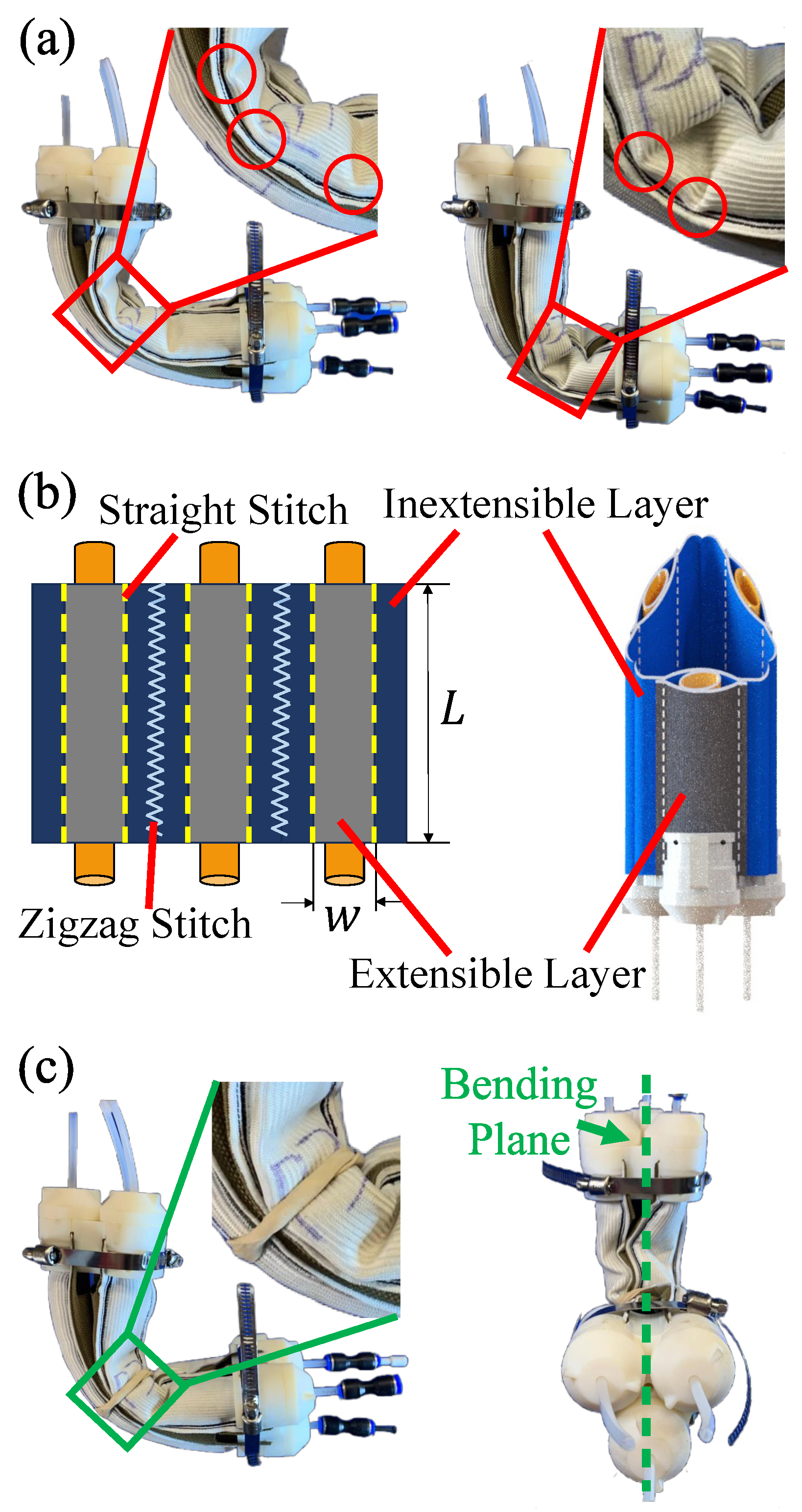
The design philosophy of the OBA is rooted in the anisotropy of knit fabrics [21,22,25,27,34]. The OBA consists of three actuation chambers that parallel along the length and 120° apart in the cross section. Each chamber is designed with a dual-fabric architecture that consists of one uni-axially extensible fabric and one strain-limiting fabric. The extensible fabric is designed to stretch significantly in the wale direction while remaining rigid in the course direction. The wale and course directions are indicated in Figure 2a. This anisotropy in the extensible fabric is achieved by integrating rubber strings with fabric threads to allow elasticity in one axis and resistance in the other. Upon pressurization, each chamber can bend uni-directionally due to the difference in the extent of extension of the two layers. By incorporating three such chambers together and pressurizing one or more of the actuation chambers simultaneously, the OBA can demonstrate omnidirectional bending capabilities. The complete design of OBA and its components is shown in Figure 2b.
We developed multiple OBAs with varying geometrical dimensions and conducted preliminary tests to evaluate the influence of the OBA’s dimension on the working performance. Figure 2b illustrates the relationship between the length and range of motion of the OBA prototypes when a single chamber was pressurized to 414 kPa. The findings reveal a strong correlation between actuator length and bending angle: 90, 180, and 270 mm long actuators achieved a bending angle of 9.7°, 78.3°, and 136.3°, respectively. This result underscores the impact that actuator length has on the achievable range of motion, with longer actuators capable of larger bending angles under the same pressure conditions and also highlights the OBA’s ease of scalability for diverse applications. For this study, the 180 mm variant was chosen for both the demonstration of the fabrication process and OBA characterizations.
There are two potential issues that prevent the OBA from bending reliably and need to be overcome through novel fabrication approaches. The first issue involves the variability in buckling locations along the lengths of the non-pressurized chambers, where the buckling would occur at different lateral locations between the two chambers. This spatial inconsistency in buckling locations results in unintended out-of-plane bending of the OBA. The second issue is the temporal inconsistency of buckling locations across different actuation cycles, which leads to unpredictable OBA motions. As shown in Figure 3a, the same OBA has different buckling locations (red circles) between the two actuation tests.
To address these spatial and temporal inconsistencies, we invented a novel fabrication method including the following two main steps: (1) we designed the inextensible layers to be wider than the extensible layer, allowing for the inextensible layers of the three chambers to be combined in parallel by stitching along their longitudinal edges, as shown in Figure 3b, and (2) we introduced a pre-buckling mechanism by securing a rubber band around the actuator’s midsection, affecting all chambers. The diameter of the rubber band should be smaller than that of the OBA to guarantee effective compression at the interface where the rubber band contacts the fabric chambers. This compression introduces pre-buckling before actuation and thereby ensures repeatable buckling at the same locations during cyclic actuation. These adjustments successfully standardized the buckling location across repeated actuation cycles, ensuring consistent, in-plane motion as shown in Figure 3c.
In addition, we investigated the impact of material fatigue on the performance of the OBA. The difference in stiffness of the OBA components between a newly fabricated actuator and those that underwent repeated actuation cycles caused an inconsistency in the motion range between the two OBAs. This phenomenon is attributed to the inherent material properties of the OBA’s soft components (e.g., pneumatic bladder and anisotropic fabric). Initially, these materials are relatively stiff, but as material fatigue sets in, they gradually soften and become more pliable, influencing the OBA’s performance. After enduring 60 fatigue cycles, the materials reach a state of equilibrium, leading to a more consistent bending angle of the OBA. Figure 4a,b show the bending shape of the pre- and post-fatigued OBA pressurized at 414 kPa, respectively. Initially, the OBA exhibited a bending angle of 54.2°. After enduring 60 fatigue cycles, there was a notable increase in the bending angle to 88.8°. Following 120 fatigue cycles, the bending angle stabilized, showing a slight increase to 90.8°. This progression indicates that the OBA can have a substantial and consistent range of motion after 60 fatigue cycles.
2.2. Fabrication and Integration
OBA fabrication entails constructing a fabric sleeve that combines two specific fabric components: the anisotropic fabric (152.4 mm Wide White Heavy Stretch High Elasticity Knit Elastic Band, Cisone, China), extensible only in the wale direction, and an inextensible fabric (1050 Denier Coated Ballistic Nylon Fabric, Magna Fabrics, Cresskill, NJ, USA). Wale and course directions of the fabrics are indicated in Figure 2a. Both fabric components are cut to a 180 mm length along the wale direction. The inextensible fabric is wider, with a width of 76 mm, whereas the anisotropic fabric measures 50 mm in width, both along the course direction. After positioning the anisotropic fabric parallel along the length and centrally along the width on the inextensible fabric, they are sewn together using straight, polyester stitches (UV Resistant High Strength Polyester Thread #69 T70 Size 210D/3, Selric, China) from a sewing machine. Each stitch line is passed over three times and spaced 33 mm apart in width. Following this, three of these combined sleeves are produced and subsequently joined along their length with a zigzag stitch. This stitch is sewn from the inside, ensuring that upon inverting the assembly, clean seams are visible. This process is illustrated in Figure 3b.
Each sleeve houses a silicone pneumatic bladder (Silicone Tubing, 14.3 mm ID × 15.9 mm OD, Quickun, Seattle, Washington) of 210 mm in length. At both ends of these bladders, a pneumatic tube (Pneumatic Tubing 4 mm OD × 2 mm ID, Uxcell, Hong Kong, China) is attached, which connects to a 3D-printed bladder collar. This component, once secured inside the bladder, functions as the pressurized air inlet. After inserting the bladder, the open ends of the assembly are sealed with 3D-printed end caps. This end cap features a three-component, self-sealing design, comprising a pair of near symmetrical pieces on the left and right that clamp the fabric sleeve securely in place. Additionally, a threaded top piece completes the assembly by fastening onto the left and right components, ensuring the entire structure is tightly secured [46]. This ensures the bladder remains contained within the sleeve during pressurization. A comprehensive visual of this fabrication procedure can be seen in Figure 2a and the finalized OBA assembly can be found in Figure 1. The completed OBA measures 229 mm in length and 68 mm in diameter.
The pneumatic system comprises an air compressor (Silver-Line Modell L-S50-25, Planet-Air, Ahrensburg, Germany), pressure sensors (Sensor 150 PSIG 0.19″ 12 BIT 8 DIP, Honeywell, Charlotte, NC, USA) for individual OBA pneumatic chambers, and solenoid valves (SY113-SMO-PM3-F, SMC Pneumatics, Tokyo, Japan) to dictate airflow. This setup enables precise chamber pressurization monitoring and control for coordinated pressurization of the individual chambers of the OBA. The full pneumatic system setup can be seen in Figure 5a.
3. Experimental Characterizations and Demonstrations
3.1. Experimental Setup
Two experimental platforms were devised to assess the motion range and bending torque capabilities of the OBA, respectively. For all tests, the 180 mm long OBA was used. The first platform employs an electromagnetic (EM) tracking system (Aurora, Northern Digital Inc., Waterloo, Ontario, Canada) consisting of an EM field generator and a 6-DoF EM sensor as shown in Figure 5a. The OBA was vertically mounted on a static frame at one end and had the EM sensor affixed to its free end. A global coordinate frame was shown in Figure 5a with its z-axis aligned along the length of the OBA and the x-axis aligned along the width of the EM field generator. During the coordinated actuation of the OBA’s chambers, we used this platform to measure the position and orientation of the free end of the OBA.
The second platform features a 6-DoF load cell (Delta F/T Transducer, ATI Industrial Automation, Apex, NC, USA) mounted on a linear guide rail system as shown in Figure 5b. One end of the OBA was fixed to a static frame and the other end was attached to the load cell mounted on the carriage of the guide rail via 3D-printed attachments, with the orientation and positioning of the chambers being depicted in Figure 5b. A local coordinate frame was attached at the interface between the load cell and OBA attachment with its y-axis parallel to the actuator’s length and z-axis pointing upwards. When the OBA was pressurized, the torque measurements around the x-axis () and z-axis () were regarded as the bending torques of the OBA. However, since the OBA slightly extends when it is pressurized, a torque, which will be blended with the bending torque in the x-axis, will be generated due to the extension force and moment arm between the OBA axis and the load cell if both ends of the OBA are constrained. In this platform, due to the use of the guide rail, the OBA is allowed to slightly extend when pressurized so that can precisely represent the torque induced by the blocked x-axial bending motion of the OBA. With this platform, we measured the direction and magnitude of torque for a specific set of pressures when pressurizing individual or combined chambers.
3.2. Load-Free Workspace Measurement
The omnidirectional bending capabilities of the OBA were assessed under load-free conditions by coordinated pressurization of the OBA’s chambers. First, we evaluated the position of the free end of the OBA when each chamber was actuated individually. We varied the pressure from 103 kPa, increasing in increments of 103 kPa, up to 414 kPa. During each actuation, the 3D position and orientation of the sensor at the OBA’s tip was recorded by the EM sensor. Next, the OBA’s position was measured when two chambers were pressurized simultaneously at equal pressures. All three combinations of two chamber pressurization were tested. Lastly, with one chamber held at the pressure of 414 kPa, the pressure in another chamber was varied from 103 kPa to 310 kPa in 103 kPa increments.
To ensure the reliability of our findings, each test for the same pressurization condition was repeated three times. Our measurements showed a maximum position difference (Euclidean distance) of ±0.70 mm and an average difference of ±0.34 mm for the three repeated tests among all workspace data. The high repeatability demonstrated the advantage of our design and fabrication method as explained in Section 2. Figure 6a shows the 2D visualization of the OBA’s tip position measurements in the x–y plane obtained by averaging results from three repeated tests. This figure is annotated with labels P1, P2, and P3, corresponding to the OBA’s individual chambers. Directional arrows are used to indicate the specific bending direction associated with each chamber. Colors denote the chamber combinations, while the shapes denote the pressure levels, as indicated in the legend in Figure 6c. This common legend applies to all subsequent characterization plots. The notation “/” signifies configurations where the pressure in the chamber listed to the left of the “/” symbol is adjusted, while the chamber on the right side of this symbol is maintained at a constant pressure of 414 kPa. It is evident that by manipulating different chamber pressures, the OBA can cover a significant area in the x–y plane with any points within the circular boundary being attainable. (P3 = 414 kPa, P2 = 103 kPa) is an outlier as it did not displace as significantly as the other symmetrically equivalent points. This may be due to the imperfect fabrication of the OBA, where the three chambers may not lay perfectly parallel with each other, as it could slightly shift its orientation during integration. Also, friction between the silicone tubing and fabric may not be perfectly equivalent across all chambers, which can cause inconsistent motions. Figure 6b further elaborates on the OBA’s omnidirectional bending capabilities in 3D space. Each data point represents the averaged x–y–z position of the OBA’s tip under specific chamber pressure configurations. The dome-like shaded surface represents the 3D workspace of the OBA’s tip. The analysis of the figure reveals that actuating a single chamber in the OBA results in larger bending angles compared to double chamber actuation at the same pressure. Specifically, the maximum bending angle achieved with single-chamber actuation was 90.80°, while for double chamber actuation, it was 79.19°. These bending angles were calculated as averages across all feasible chamber combinations for each actuation mode. The observed difference in bending performance between single and double chamber actuation can be attributed to the increased friction between the pneumatic bladder and the fabric sleeve when two chambers are activated simultaneously. This increase in friction likely arises from the intersecting and conflicting bending directions of the two chambers.
3.3. Force Output Measurement
Soft actuators can exert force on environments as they deform from their equilibrium configurations. The force output increases as the difference between the current and equilibrium configurations becomes larger. In this study, we blocked the OBA in its straight configuration using the setup in Figure 5b and measured the OBA’s torque output under different pressures of the chambers. In this study, we replicated the methodology outlined in Section 3.2, which involved altering the combination of pressurized chambers and adjusting the pressures within each chamber. Each test was repeated three times.
Figure 6c shows a scatter plot that visualizes the averaged torque values, and , produced by the OBA under varying pressure settings. The actuator can generate any torque value within the hexagonal boundary presented. Using the local coordinate frame defined in Figure 5b, is the torque around the x-axis and around the z-axis. Torque was neglected since its maximum value is only 0.09 Nm. As indicated by the common legend, colors and shapes represent various combination of chambers and pressure variations. Notably, the maximum torque observed during single-chamber pressurization at 414 kPa was 1.69 ± 0.01 N·m. For double-chamber pressurization, it reached a higher torque of 1.87 ± 0.03 N·m. It is worth noting that the OBA can achieve higher negative torques (pressing down) around the x-axis than in the positive direction (pulling up), while around the z-axis, the torques are almost symmetrical. As stated in the previous section, misalignments during integration and frictional issues may cause this asymmetric phenomenon. Among the three repeated tests in all the cases, the maximum deviation is 0.03 N·m and average deviation is 0.006 N·m. These variances are minor relative to the overall torque measurements. Again, the high repeatability of torque output demonstrated the advantage of our design and fabrication method. The results of this characterization underscores the OBA’s capability to generate torques in various directions, with the magnitude and orientation of the torques being influenced by the combination of chamber pressurization and pressure variation.
To further evaluate the OBA’s robustness and capability for higher force outputs, a burst test was conducted to determine its maximum pressure tolerance. The results showed that each chamber of the OBA can withstand pressure up to 862 kPa without rupturing, indicating not only the OBA’s durability but also suggesting its potential for managing higher payloads effectively and producing greater force outputs than those demonstrated in the torque tests.
3.4. Stiffness Modulation
The OBA is able to change its bending stiffness through antagonistic actuation of its chambers, as outlined in prior studies for other soft actuators consisting of multiple chambers [47,48]. To characterize the OBA’s capability for antagonistic actuation, we positioned the OBA horizontally and secured it at one end. The cross-sectional view of the mounted OBA, shown in the upper-right corner of Figure 7a, is designated as the vertical orientation. Subsequently, we simultaneously pressurized its three chambers, denoted as P1, P2, and P3. For simplicity, we assumed symmetry of the three chambers and therefore incrementally increased the pressure in chamber P1 while maintaining constant pressure in chambers P2 and P3. An EM sensor was positioned at the OBA’s free end and utilized to measure the OBA’s bending angle. Figure 7b shows the methodology used to define the measurement angle, which is determined by the angular change at the actuator tip in the sagittal plane (i.e., angular displacement of the two red lines). Figure 7a displays the angular displacement per pressure combination, with the colored arrows indicating the bending directions of individual chambers. Each pressurization routine was repeated three times, and the results in Figure 7a show the average displacement and its standard deviation for each case. The observed trend reveals a decrease in angular displacement with increasing pressure in chamber P1 and thus demonstrates the OBA’s capability for antagonistic actuation.
To characterize the OBA’s capability for stiffness modulation via antagonistic actuation, an experimental setup was designed where the OBA maintained a constant equilibrium angle under increasing antagonistic forces. In this study, the pressure in all three chambers was equalized to maintain a nearly 0° equilibrium angle and a straight and rigid natural shape of the OBA throughout variations in chamber pressure, as evident from the four lowest data points in Figure 7a. The pressure within all chambers of the OBA was increased in 103 kPa increments up to 414 kPa. For each pressure setting, a 100 g payload was attached to the tip of the OBA. The resultant angular displacement was measured using the EM sensor and the same methodology as the previous study. This procedure was repeated three times for each pressure level. The upper plot in Figure 7b shows the absolute angular displacement of the OBA under the payload for each pressure scenario. The data points show the average and standard deviation of the three repeats. The two lower images in Figure 7b show the shape of the OBA in the vertical cross-sectional configuration under 100 g load when all chamber pressures are set to 103 kPa (upper image) and 414 kPa (lower image), corresponding to the points in the orange and blue boxes in the upper plot, respectively. Analysis of the plot shown in Figure 7b reveals a trend where an increase in chamber pressure leads to a reduction in load-induced displacement, signifying effective stiffness modulation. Specifically, the results evidence a substantial enhancement in stiffness, quantified as a more than threefold increase (3.22 times) from the lowest (103 kPa) to the highest (414 kPa) pressure settings.
To confirm that stiffness modulation can be achieved regardless of the actuator’s orientation, the OBA in the vertical cross-sectional orientation was rotated 90° around its longitudinal axis to the horizontal orientation (see Figure 7c) and subjected to the same experimental conditions. This alteration aimed to test the OBA’s performance under a different gravitational vector to individual chambers of the OBA. Figure 7b compares the outcomes of these tests, using blue and red data points to represent the vertical and horizontal orientations, respectively. At lower pressures, the displacement discrepancies and antagonistic stiffening between the vertical and horizontal cross-sectional orientations were pronounced. However, at elevated pressures, load-induced displacements were nearly identical, verifying the omnidirectional stiffness modulation capacity of the OBA. Figure 7c shows various cross-sectional orientations of the OBA, with the black arrows acting as reference markers to delineate the orientation. Since the 0° and 60° orientations exhibit horizontal line symmetry and the 30° and 90° orientations mirror each other vertically, it is unnecessary to conduct tests for 30° and 60° cross-sectional orientations and the results of 0° and 90° orientations represent OBA’s comprehensive behavior across all orientations.
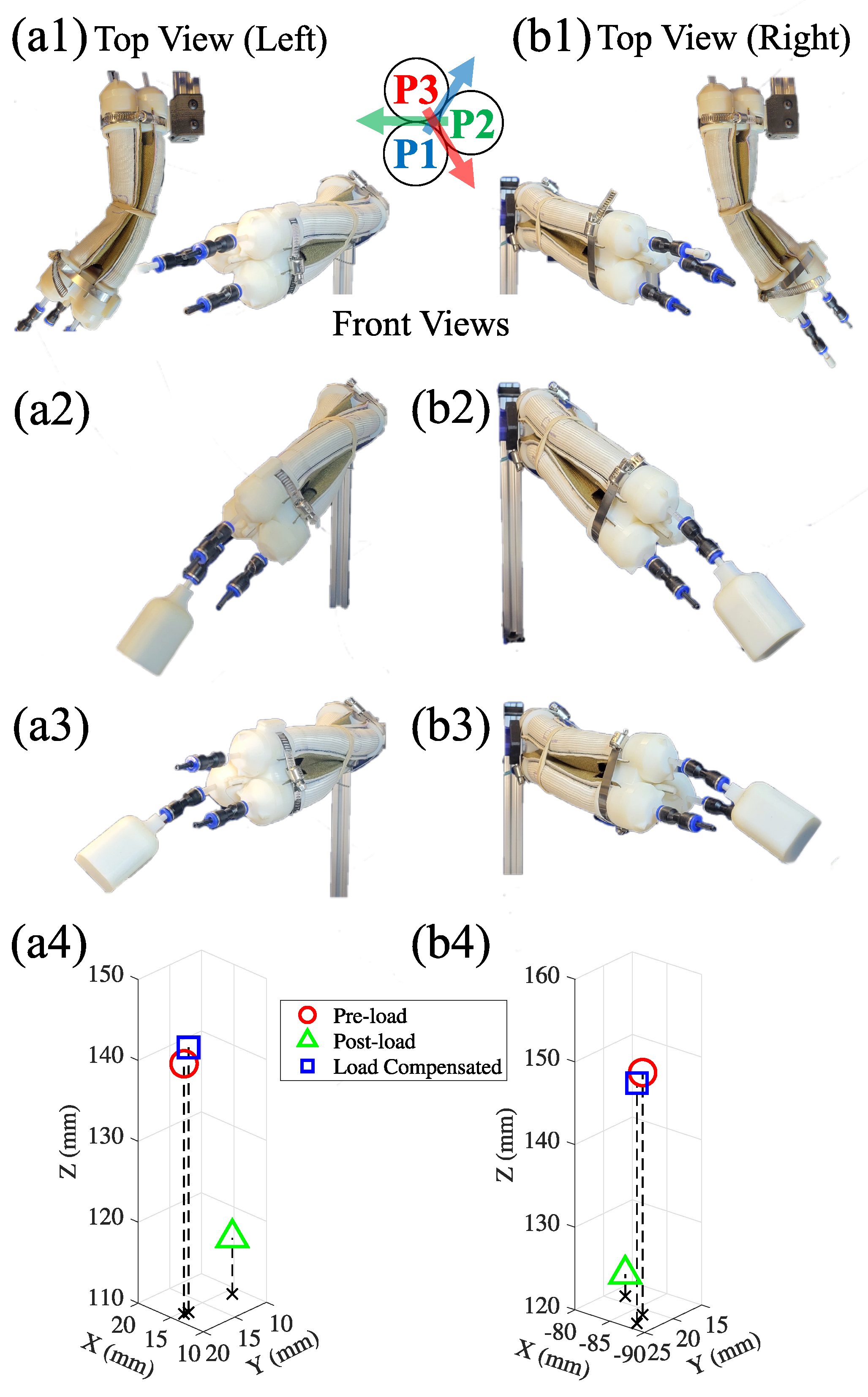
3.5. Out-of-Plane Deformation Compensation
Due to the OBA’s omnidirectional bending capability, the OBA can mitigate unwanted out-of-plane deformations induced by payloads. This feature distinguishes the OBA from traditional bidirectional in-plane bending soft actuators, which typically can adjust for deformations along its bending plane but struggle to address deformations that extend beyond this plane. To demonstrate this ability, the OBA was mounted horizontally on one end in the horizontal cross-sectional orientation. An EM sensor was used to measure the position of the OBA’s free end. Each test was repeated three times. Figure 8(a1,b1) show the OBA’s bidirectional bending motion (left and right, respectively) from the top and front perspectives after pressurization and before any payload was applied. The applied pressures and position measurements for these states are listed in Table 1 under “Left/Pre-load” and “Right/Pre-load.” This configuration serves as the reference state to which subsequent deformations and compensations are compared.
Upon applying a 100 g payload, the OBA’s deformation is shown in Figure 8(a2,b2), reflecting the actuator’s response to external forces due to its inherent compliance. In the left bending scenario, the actuator’s free end deviated by 25.0 mm (X = 0.4 mm, Y = 7.2 mm, Z = 23.9 mm), while in the opposite direction, a displacement of 27.3 mm was observed (X= 4.8 mm, Y = 2.8 mm, Z = 26.7 mm). Detailed measurements of these displacements are listed in Table 1 under “Left/Post-load” and ”Right/Post-load.”
A notable feature of the OBA is its compensatory motion that actively counteracts load-induced deformations by modulating the chamber pressures, as shown in Figure 8(a3,b3). In both scenarios, the OBA nearly returns to its original pre-loaded state, showing minor deviations of approximately ±1.9 mm and ±2.5 mm for the left and right bending scenarios, respectively. The chamber pressures enabling this compensation are listed in Table 1 under “Left/Compensated” and “Right/Compensated.” The determination of these compensatory pressures was achieved through trial and error. In future work, we will develop an autonomous pressure modulation approach aided by sensor feedback. Figure 8(a4,b4) show the averaged tip positions across the three main deformation states: pre-load, post-load, and post-compensation. This experiment highlights the OBA’s ability to compensate for out-of-plane deformations, underscoring its potential in scenarios where the capacity to adjust to varying external loads is crucial. While the current focus is on its static response, the superior motion capabilities observed suggests a promising foundation for further exploration into its dynamic responsiveness across various load conditions.
4. Discussion and Conclusions
In this paper, we presented the development and characterization of the omnidirectional bending OBA. The design and fabrication method is straightforward and reliable, enabling large workspace and reliable motion and torque output. We also characterized and demonstrated the OBA’s capabilities for stiffness modulation and deformation compensation, which make OBA potential for practical applications under various payloads. Table 2 provides a comparative analysis of the OBA relative to two other omnidirectional fabric actuators that can be found in the literature: an omnidirectional knit fabric actuator in [34] and a woven fabric-based actuator from [33]. A notable feature of the OBA is its streamlined fabrication process, which employs a minimal set of fabrication tools to achieve efficient construction (see Video S1). This methodology enhances the accessibility and practicality of the OBA for real-world applications while ensuring it remains competitive in performance metrics when compared to similar actuators. Regarding physical attributes, the OBA demonstrates a reduced mass and volume, yet provides a range of motion (RoM) and payload capacity comparable to those of its counterparts, with the reduced mass contributing to a superior force-to-weight ratio. However, it is essential to acknowledge the unique twisting and extending capabilities of the actuator documented in [34]. While [33] shows an actuator with a higher bending payload, it has longer actuator length. Notably, the comparison includes [33], which utilizes a different fabric type (woven), making [34] a more pertinent benchmark given its use of knit fabric. In summary, the OBA distinguishes itself by its more lightweight and compact design with higher pressure capabilities when compared to the sole other actuator in its class, without compromising critical performance metrics such as RoM and bending payload capacity.
In the future, to address the potential issues of hysteresis and slow response of pneumatic systems [49,50,51], we will focus on characterizing the dynamic behavior of the actuator and build a data-driven controller for the OBA. Additionally, we will integrate sensors into the OBA to enable a feedback-controlled system, allowing real-time adjustments of OBA’s shape and stiffness. We will also optimize the design of the pneumatic system for quicker response times to compensate for the inherent latency in pneumatic actuation. The performance disparities among the three actuation chambers of the OBA will also be mitigated by transitioning from manual sewing methods, which can lead to variations in stitches and fabric dimensions to employing computerized sewing machines and laser cutters. By standardizing production processes, inconsistencies related to fabrication will be minimized, improving OBA performance. Furthermore, we will refine the OBA and integrate it into a wearable assistive robot for upper limb assistance. Its lightweight and compact nature, combined with its capable payload performance and efficient fabrication process, makes it a potential candidate for the development of wearable assistive robots. Additional actuation modes, such as contraction, twisting, and elongation, will also be explored to enhance the OBA’s applicability. These expanded functionalities, combined with the OBA’s omnidirectional motion capability and ability to modulate stiffness, will be particularly beneficial for assisting movements of intricate joints, such as the shoulder. In addition, the OBA’s design features, including ease of scalability and high pressure capabilities, contribute to its versatility and durability, which are particularly aligned with the requirements of wearable robots.
Supplementary Materials
The following supporting information can be downloaded at: https://0-www-mdpi-com.brum.beds.ac.uk/article/10.3390/act13030112/s1, Video S1: OBA Fabrication and Demonstration.
Author Contributions
Conceptualization, K.L., J.S. and J.R.; methodology, K.L. and J.S.; software, K.L. and K.B.; validation, K.L., G.A. and J.S.; formal analysis, K.L., K.B. and J.S.; investigation, K.L., K.B. and G.A.; resources, J.S. and J.R.; data curation, K.L., K.B. and G.A.; writing—original draft preparation, K.L. and J.S.; writing—review and editing, K.L., J.S. and J.R.; visualization, K.L., K.B. and G.A.; supervision, K.L., J.S. and J.R.; project administration, K.L., J.S. and J.R; funding acquisition, J.S. and J.R. All authors have read and agreed to the published version of the manuscript.
Funding
Research reported in this publication was supported by the National Science Foundation under Award Number 2221315. The content is solely the responsibility of the authors and does not necessarily represent the official views of National Science Foundation.
Data Availability Statement
Data are contained within the article. Further inquiries can be directed to the corresponding author.
Acknowledgments
The authors extend their sincere appreciation to Tuo Liu from the Bionic Systems Lab (BSL), University of California, Riverside, USA for his help with actuator design.
Conflicts of Interest
The authors declare no conflicts of interest.
Abbreviations
The following abbreviations are used in this manuscript:
| OBA | Omnidirectional Bending Actuator |
| PAM | Pneumatic artificial muscle |
| DoF | Degree of freedom |
| EM | Electromagnetic |
| RoM | Range of motion |
References
- Simpson, C.S.; Okamura, A.M.; Hawkes, E.W. Exomuscle: An inflatable device for shoulder abduction support. In Proceedings of the 2017 IEEE International Conference on Robotics and Automation (ICRA), Singapore, 29 May–3 June 2017; pp. 6651–6657. [Google Scholar] [CrossRef]
- Yap, H.K.; Khin, P.M.; Koh, T.H.; Sun, Y.; Liang, X.; Lim, J.H.; Yeow, C.H. A Fully Fabric-Based Bidirectional Soft Robotic Glove for Assistance and Rehabilitation of Hand Impaired Patients. IEEE Robot. Autom. Lett. 2017, 2, 1383–1390. [Google Scholar] [CrossRef]
- Jarrassé, N.; Morel, G. Connecting a human limb to an exoskeleton. IEEE Trans. Robot. 2011, 28, 697–709. [Google Scholar] [CrossRef]
- Galiana, I.; Hammond, F.L.; Howe, R.D.; Popovic, M.B. Wearable soft robotic device for post-stroke shoulder rehabilitation: Identifying misalignments. In Proceedings of the 2012 IEEE/RSJ International Conference on Intelligent Robots and Systems, Vilamoura-Algarve, Portugal, 7–12 October 2012; pp. 317–322. [Google Scholar] [CrossRef]
- Xavier, M.S.; Tawk, C.D.; Zolfagharian, A.; Pinskier, J.; Howard, D.; Young, T.; Lai, J.; Harrison, S.M.; Yong, Y.K.; Bodaghi, M.; et al. Soft Pneumatic Actuators: A Review of Design, Fabrication, Modeling, Sensing, Control and Applications. IEEE Access 2022, 10, 59442–59485. [Google Scholar] [CrossRef]
- Hawkes, E.W.; Blumenschein, L.H.; Greer, J.D.; Okamura, A.M. A soft robot that navigates its environment through growth. Sci. Robot. 2017, 2, eaan3028. [Google Scholar] [CrossRef] [PubMed]
- Liu, Z.; Lu, Z.; Karydis, K. SoRX: A Soft Pneumatic Hexapedal Robot to Traverse Rough, Steep, and Unstable Terrain. In Proceedings of the 2020 IEEE International Conference on Robotics and Automation (ICRA), Paris, France, 31 May–31 August 2020; pp. 420–426. [Google Scholar] [CrossRef]
- Laut, J.; Porfiri, M.; Raghavan, P. The present and future of robotic technology in rehabilitation. Curr. Phys. Med. Rehabil. Rep. 2016, 4, 312–319. [Google Scholar] [CrossRef] [PubMed]
- Schiele, A.; van der Helm, F.C.T. Influence of attachment pressure and kinematic configuration on pHRI with wearable robots. Appl. Bionics Biomech. 2009, 6, 157–173. [Google Scholar] [CrossRef]
- O’Neill, C.T.; Phipps, N.S.; Cappello, L.; Paganoni, S.; Walsh, C.J. A soft wearable robot for the shoulder: Design, characterization, and preliminary testing. In Proceedings of the 2017 International Conference on Rehabilitation Robotics (ICORR), London, UK, 17–20 July 2017; pp. 1672–1678. [Google Scholar] [CrossRef]
- Coyle, S.; Majidi, C.; LeDuc, P.; Hsia, K.J. Bio-inspired soft robotics: Material selection, actuation, and design. Extrem. Mech. Lett. 2018, 22, 51–59. [Google Scholar] [CrossRef]
- Nguyen, P.H.; Zhang, W. Design and Computational Modeling of Fabric Soft Pneumatic Actuators for Wearable Assistive Devices. Sci. Rep. 2020, 10, 9638. [Google Scholar] [CrossRef]
- Zhang, J.; Sheng, J.; O’Neill, C.T.; Walsh, C.J.; Wood, R.J.; Ryu, J.H.; Desai, J.P.; Yip, M.C. Robotic Artificial Muscles: Current Progress and Future Perspectives. IEEE Trans. Robot. 2019, 35, 761–781. [Google Scholar] [CrossRef]
- Thalman, C.; Artemiadis, P. A review of soft wearable robots that provide active assistance: Trends, common actuation methods, fabrication, and applications. Wearable Technol. 2020, 1, e3. [Google Scholar] [CrossRef]
- Wehner, M.; Quinlivan, B.; Aubin, P.M.; Martinez-Villalpando, E.; Baumann, M.; Stirling, L.; Holt, K.; Wood, R.; Walsh, C. A lightweight soft exosuit for gait assistance. In Proceedings of the 2013 IEEE International Conference on Robotics and Automation, Karlsruhe, Germany, 6–10 May 2013; pp. 3362–3369. [Google Scholar] [CrossRef]
- Teng, C.; Wong, Z.; Teh, W.; Chong, Y.Z. Design and development of inexpensive pneumatically-powered assisted knee-ankle-foot orthosis for gait rehabilitation-preliminary finding. In Proceedings of the 2012 International Conference on Biomedical Engineering (ICoBE), Penang, Malaysia, 27–28 February 2012; pp. 28–32. [Google Scholar] [CrossRef]
- Davis, S.; Tsagarakis, N.; Canderle, J.; Caldwell, D.G. Enhanced Modelling and Performance in Braided Pneumatic Muscle Actuators. Int. J. Robot. Res. 2003, 22, 213–227. [Google Scholar] [CrossRef]
- Wang, J.; Fei, Y.; Pang, W. Design, modeling, and testing of a soft pneumatic glove with segmented PneuNets bending actuators. IEEE/ASME Trans. Mechatron. 2019, 24, 990–1001. [Google Scholar] [CrossRef]
- Polygerinos, P.; Wang, Z.; Galloway, K.C.; Wood, R.J.; Walsh, C.J. Soft robotic glove for combined assistance and at-home rehabilitation. Rob. Auton. Syst. 2015, 73, 135–143. [Google Scholar] [CrossRef]
- Oguntosin, V.; Harwin, W.S.; Kawamura, S.; Nasuto, S.J.; Hayashi, Y. Development of a wearable assistive soft robotic device for elbow rehabilitation. In Proceedings of the 2015 IEEE International Conference on Rehabilitation Robotics (ICORR), Singapore, 11–14 August 2015; pp. 747–752. [Google Scholar] [CrossRef]
- Connolly, F.; Wagner, D.A.; Walsh, C.J.; Bertoldi, K. Sew-free anisotropic textile composites for rapid design and manufacturing of soft wearable robots. Extrem. Mech. Lett. 2019, 27, 52–58. [Google Scholar] [CrossRef]
- Cappello, L.; Meyer, J.T.; Galloway, K.C.; Peisner, J.D.; Granberry, R.; Wagner, D.A.; Engelhardt, S.; Paganoni, S.; Walsh, C.J. Assisting hand function after spinal cord injury with a fabric-based soft robotic glove. J. Neuroeng. Rehabil. 2018, 15, 59. [Google Scholar] [CrossRef] [PubMed]
- Chung, J.; Heimgartner, R.; Oneill, C.T.; Phipps, N.S.; Walsh, C.J. ExoBoot, a Soft Inflatable Robotic Boot to Assist Ankle During Walking: Design, Characterization and Preliminary Tests. In Proceedings of the 2018 7th IEEE International Conference on Biomedical Robotics and Biomechatronics (Biorob), Enschede, The Netherlands, 26–29 August 2018; pp. 509–516. [Google Scholar] [CrossRef]
- Yang, H.D.; Asbeck, A.T. A New Manufacturing Process for Soft Robots and Soft/Rigid Hybrid Robots. In Proceedings of the 2018 IEEE/RSJ International Conference on Intelligent Robots and Systems (IROS), Madrid, Spain, 1–5 October 2018; pp. 8039–8046. [Google Scholar] [CrossRef]
- Realmuto, J.; Sanger, T. A robotic forearm orthosis using soft fabric-based helical actuators. In Proceedings of the 2019 2nd IEEE International Conference on Soft Robotics (RoboSoft), Seoul, Republic of Korea, 14–18 April 2019; pp. 591–596. [Google Scholar] [CrossRef]
- Connelly, L.; Jia, Y.; Toro, M.L.; Stoykov, M.E.; Kenyon, R.V.; Kamper, D.G. A Pneumatic Glove and Immersive Virtual Reality Environment for Hand Rehabilitative Training After Stroke. IEEE Trans. Neural Syst. Rehabil. Eng. 2010, 18, 551–559. [Google Scholar] [CrossRef] [PubMed]
- Cappello, L.; Galloway, K.C.; Sanan, S.; Wagner, D.A.; Granberry, R.; Engelhardt, S.; Haufe, F.L.; Peisner, J.D.; Walsh, C.J. Exploiting Textile Mechanical Anisotropy for Fabric-Based Pneumatic Actuators. Soft Robot. 2018, 5, 662–674. [Google Scholar] [CrossRef] [PubMed]
- Park, S.H.; Yi, J.; Kim, D.; Lee, Y.; Koo, H.S.; Park, Y.L. A Lightweight, Soft Wearable Sleeve for Rehabilitation of Forearm Pronation and Supination. In Proceedings of the 2019 2nd IEEE International Conference on Soft Robotics (RoboSoft), Seoul, Republic of Korea, 14–18 April 2019; pp. 636–641. [Google Scholar] [CrossRef]
- Ezzibdeh, R.; Arora, P.; Amanatullah, D.F. Utilization of a pneumatic exoskeleton after total knee arthroplasty. Arthroplast. Today 2019, 5, 314–315. [Google Scholar] [CrossRef] [PubMed]
- Fraiszudeen, A.; Yeow, C.H. Soft Actuating Sit-to-Stand Trainer Seat. J. Mech. Robot. 2019, 11, 014501. [Google Scholar] [CrossRef]
- Koh, T.H.; Cheng, N.; Yap, H.K.; Yeow, C.H. Design of a Soft Robotic Elbow Sleeve with Passive and Intent-Controlled Actuation. Front. Neurosci. 2017, 11, 597. [Google Scholar] [CrossRef] [PubMed]
- Abrar, T.; Putzu, F.; Konstantinova, J.; Althoefer, K. EPAM: Eversive Pneumatic Artificial Muscle. In Proceedings of the 2019 2nd IEEE International Conference on Soft Robotics (RoboSoft), Seoul, Republic of Korea, 14–18 April 2019; pp. 19–24. [Google Scholar] [CrossRef]
- Nguyen, P.H.; Mohd, I.B.I.; Sparks, C.; Arellano, F.L.; Zhang, W.; Polygerinos, P. Fabric Soft Poly-Limbs for Physical Assistance of Daily Living Tasks. In Proceedings of the 2019 International Conference on Robotics and Automation (ICRA), Montreal, QC, Canada, 20–24 May 2019; pp. 8429–8435. [Google Scholar] [CrossRef]
- Nguyen, P.H.; Qiao, Z.; Seidel, S.; Amatya, S.; Mohd, I.I.B.; Zhang, W. Towards an Untethered Knit Fabric Soft Continuum Robotic Module with Embedded Fabric Sensing. In Proceedings of the 2020 3rd IEEE International Conference on Soft Robotics (RoboSoft), New Haven, CT, USA, 15 May–15 July 2020; pp. 615–620. [Google Scholar] [CrossRef]
- Ma, J.; Chen, D.; Liu, Z.; Wei, J.; Zhang, X.; Zeng, Z.; Jiang, Y. All-Fabric Bi-directional Actuators for Multi-joint Assistance of Upper Limb. J. Bionic Eng. 2023, 20, 2661–2669. [Google Scholar] [CrossRef]
- Natividad, R.F.; Miller-Jackson, T.; Chen-Hua, R.Y. A 2-DOF Shoulder Exosuit Driven by Modular, Pneumatic, Fabric Actuators. IEEE Trans. Med. Robot. Bionics 2021, 3, 166–178. [Google Scholar] [CrossRef]
- Liang, X.; Yap, H.K.; Guo, J.; Yeow, R.C.H.; Sun, Y.; Chui, C.K. Design and characterization of a novel fabric-based robotic arm for future wearable robot application. In Proceedings of the 2017 IEEE International Conference on Robotics and Biomimetics (ROBIO), Macau, Macao, 5–8 December 2017; pp. 367–372. [Google Scholar] [CrossRef]
- Thalman, C.M.; Lam, Q.P.; Nguyen, P.H.; Sridar, S.; Polygerinos, P. A Novel Soft Elbow Exosuit to Supplement Bicep Lifting Capacity. In Proceedings of the 2018 IEEE/RSJ International Conference on Intelligent Robots and Systems (IROS), Madrid, Spain, 1–5 October 2018; pp. 6965–6971. [Google Scholar] [CrossRef]
- Sovero, S.; Talele, N.; Smith, C.; Cox, N.; Swift, T.; Byl, K. Initial Data and Theory for a High Specific-Power Ankle Exoskeleton Device. In Proceedings of the 2016 International Symposium on Experimental Robotics, ISER, Nagasaki, Japan, 3–8 October 2016; Springer: Cham, Switzerland, 2017; pp. 355–364. [Google Scholar] [CrossRef]
- Park, Y.L.; Rong Chen, B.; Pérez-Arancibia, N.O.; Young, D.; Stirling, L.; Wood, R.J.; Goldfield, E.C.; Nagpal, R. Design and control of a bio-inspired soft wearable robotic device for ankle–foot rehabilitation. Bioinspiration Biomim. 2014, 9, 016007. [Google Scholar] [CrossRef] [PubMed]
- Zhu, M.; Adams, W.; Polygerinos, P. Carpal Tunnel Syndrome Soft Relief Device for Typing Applications. In Proceedings of the 2017 Design of Medical Devices Conference, Minneapolis, MN, USA, 10–13 April 2017; p. V001T03A003. [Google Scholar] [CrossRef]
- Sanan, S.; Lynn, P.S.; Griffith, S.T. Pneumatic Torsional Actuators for Inflatable Robots. J. Mech. Robot. 2014, 6, 031003. [Google Scholar] [CrossRef]
- Nishioka, Y.; Uesu, M.; Tsuboi, H.; Kawamura, S.; Masuda, W.; Yasuda, T.; Yamano, M. Development of a pneumatic soft actuator with pleated inflatable structures. Adv. Robot. 2017, 31, 753–762. [Google Scholar] [CrossRef]
- Govin, D.; Saenz, L.; Athanasaki, G.; Snyder, L.; Polygerinos, P. Design and Development of a Soft Robotic Back Orthosis. In Proceedings of the 2018 Design of Medical Devices Conference, Minneapolis, MN, USA, 9–12 April 2018. [Google Scholar] [CrossRef]
- Natividad, R.F.; Hong, S.W.; Miller-Jackson, T.M.; Yeow, C.H. The Exosleeve: A Soft Robotic Exoskeleton for Assisting in Activities of Daily Living. In Wearable Robotics: Challenges and Trends, WeRob 2018, Biosystems & Biorobotics; Springer: Cham, Switzerland, 2019; pp. 406–409. [Google Scholar] [CrossRef]
- Liu, T.; Abrar, T.; Realmuto, J. Modular and Reconfigurable Body Mounted Soft Robots. In Proceedings of the 2024 7th IEEE-RAS International Conference on Soft Robotics (RoboSoft), San Diego, CA, USA, 14–17 April 2024. [Google Scholar]
- Ariga, Y.; Pham, H.T.T.; Uemura, M.; Hirai, H.; Miyazaki, F. Novel equilibrium-point control of agonist-antagonist system with pneumatic artificial muscles. In Proceedings of the 2012 IEEE International Conference on Robotics and Automation, Saint Paul, MN, USA, 14–18 May 2012; pp. 1470–1475. [Google Scholar]
- Ariga, Y.; Maeda, D.; Pham, H.T.T.; Uemura, M.; Hirai, H.; Miyazaki, F. Novel equilibrium-point control of agonist-antagonist system with pneumatic artificial muscles: II. Application to EMG-based human-machine interface for an elbow-joint system. In Proceedings of the 2012 IEEE International Conference on Robotics and Automation, Saint Paul, MN, USA, 14–18 May 2012; pp. 4380–4385. [Google Scholar]
- Tassa, Y.; Wu, T.; Movellan, J.; Todorov, E. Modeling and identification of pneumatic actuators. In Proceedings of the 2013 IEEE International Conference on Mechatronics and Automation, Takamatsu, Japan, 4–7 August 2013; pp. 437–443. [Google Scholar] [CrossRef]
- Guo, X.; Li, W.; Zhang, W. Adjustable stiffness elastic composite soft actuator for fast-moving robots. Sci. China Technol. Sci. 2021, 64, 1663–1675. [Google Scholar] [CrossRef]
- Ma, Z.; Sameoto, D. A Review of Electrically Driven Soft Actuators for Soft Robotics. Micromachines 2022, 13, 1881. [Google Scholar] [CrossRef]
Figure 1.
Demonstration of the omnidirectional bending of a horizontally mounted OBA: (a) Top view showing lateral bending, with left bending achieved through pressurization of one chamber to 414 kPa and right bending through pressurization of two chambers to 414 kPa. (b) Front view showing the OBA’s ability to perform bending motions across 360°, achieved by pressurizing each chamber to 414 kPa for all three configurations.

Figure 2.
Design of the OBA: (a) labeled diagram of the OBA and its components, with fabric wale and course directions indicated. (b) 90, 180, and 270 mm long actuators (descending) bend to 9.7°, 78.3°, 136.3°, respectively, while pressurizing one chamber in each actuator to 414 kPa.
Figure 2.
Design of the OBA: (a) labeled diagram of the OBA and its components, with fabric wale and course directions indicated. (b) 90, 180, and 270 mm long actuators (descending) bend to 9.7°, 78.3°, 136.3°, respectively, while pressurizing one chamber in each actuator to 414 kPa.

Figure 3.
Buckling challenges and solutions: (a) Inconsistent actuator bending among repeated cycles due to variability in buckling locations. (b) Diagram of integrating three pneumatic chambers. (c) Consistent and in-plane actuator bending (right) of the OBA fabricated based on the proposed method involving pre-induced buckling (left). All configurations depicted were achieved by pressurizing one chamber to 414 kPa.

Figure 4.
Effects of fatigue on OBA performance: (a) Limited range of motion before material fatigue (54.2°) due to initial high stiffness of the fabric and bladder components. (b) Increased range of motion after 120 fatigue cycles (90.8°). All configuration depicted was achieved by pressurizing one chamber to 414 kPa.

Figure 5.
Experimental platforms for OBA characterization: (a) Load-free workspace measurement setup, including an EM field generator, an EM sensor attached at the free end of the actuator, and pneumatic control accessories (Red and green lines represent pneumatic and digital connections, respectively). (b) Experimental setup for force output measurement, utilizing a 6-DoF load cell and a linear rail to neutralize extension forces, with each chambers denoted as P1, P2, and P3 (Pneumatic connection is equivalent to those used for workspace measurement).

Figure 6.
Results of OBA characterization: (a) 2D (x–y plane) load-free workspace of the OBA (P1, P2, and P3 denote the actuator’s chambers and arrows denote the direction of bending for each chamber). (b) 3D load-free workspace of the OBA with highlighted red, green, and blue lines indicating the shape of the OBA during actuation (The OBA for the blue line is shown in the upper right corner). (c) Torque output of the OBA around the x– and z–axesunder different combinations of pressurized chambers and varying pressures. A common legend applies to all plots, with “/” signifying configurations where the pressure to the left of the “/” is adjusted from 103 to 310 kPa, while the pressure on the right remains constant at 414 kPa.

Figure 7.
Stiffness modulation of the OBA: (a) bending angle of the OBA under different combinations of chamber pressures. (b) (upper) angular displacement of the OBA due to a 100 g payload versus the pressure of the chambers, (middle) image of the deformed OBA at 103 kPa, and (lower) image of the deformed OBA at 414 kPa. (c) cross-sectional symmetry of the OBA: 0° and 60° exhibit horizontal symmetry while 30° and 90° exhibit vertical symmetry.

Figure 8.
Deformation compensation of the OBA with subfigures (a,b), respectively, represent the left and right bending scenarios of the OBA: (a1,b1) top and front views showing the OBA bending horizontally upon pressurization without external load. (a2,b2) Out-of-plane deformation of the OBA subjected to a 100 g payload. (a3,b3) Compensatory motion of the OBA actively counterbalancing the load-induced out-of-plane deformation by regulating the pressure of chambers. (a4,b4) 3D plots of the x–y–z position of the tip of the OBA through the stages of pre-load (red circle), post-load (green triangle), and post-compensation (blue square) states.


Table 1.
Results of Deformation Compensation Test.
| Direction/State | Position (X, Y, Z) mm | Pressure (P1, P2, P3) kPa |
|---|---|---|
| Left/Pre-load | (14.5, 18.4, 140.9) ± 0.15 | (207, 0, 207) |
| Left/Post-load | (14.1, 11.2, 117.0) ± 0.42 | (207, 0, 207) |
| Left/Compensated | (14.5, 17.7, 142.7) ± 0.15 | (338, 0, 103) |
| Right/Pre-load | (, 21.3, 149.3) ± 0.11 | (103, 207, 0) |
| Right/Post-load | (, 18.5, 122.6) ± 0.37 | (103, 207, 0) |
| Right/Compensated | (, 23.6, 149.1) ± 0.44 | (276, 290, 0) |
Table 2.
OBA Performance Comparison with State-of-the-art.
| Property | OBA | Soft Continuum Robotic Module [34] | fSPL [33] |
|---|---|---|---|
| Material | Knit fabric | Knit fabric | Woven fabric |
| Fabrication Tools | Sewing machine, 3D printer | Laser cutter, Heat press, Sewing machine, 3D printer | Laser cutter, CNC router, Sewing machine, 3D printer |
| Single-Chamber Mass | 22 g | 30 g | 364 g |
| Actuator Mass | 278 g | 400 g | 1092 g |
| Actuator Length | 229 mm | 200 mm | 590 mm |
| Actuator Diameter | 68 mm | 120 mm | 100 mm |
| Angular RoM | 90.80° | 104.02° | 180° |
| Max Pressure | 862 kPa | 690 kPa | 540 kPa |
| Bending Payload | 10.99 N (414 kPa) | 9.66 N (207 kPa) | 14.91 N (345 kPa) |
| Force-to-weight Ratio | 39.53 N/kg | 24.15 N/kg | 13.65 N/kg |
Disclaimer/Publisher’s Note: The statements, opinions and data contained in all publications are solely those of the individual author(s) and contributor(s) and not of MDPI and/or the editor(s). MDPI and/or the editor(s) disclaim responsibility for any injury to people or property resulting from any ideas, methods, instructions or products referred to in the content. |
© 2024 by the authors. Licensee MDPI, Basel, Switzerland. This article is an open access article distributed under the terms and conditions of the Creative Commons Attribution (CC BY) license (https://creativecommons.org/licenses/by/4.0/).
Share and Cite
MDPI and ACS Style
Lee, K.; Bayarsaikhan, K.; Aguilar, G.; Realmuto, J.; Sheng, J. Design and Characterization of Soft Fabric Omnidirectional Bending Actuators. Actuators 2024, 13, 112. https://0-doi-org.brum.beds.ac.uk/10.3390/act13030112
AMA Style
Lee K, Bayarsaikhan K, Aguilar G, Realmuto J, Sheng J. Design and Characterization of Soft Fabric Omnidirectional Bending Actuators. Actuators. 2024; 13(3):112. https://0-doi-org.brum.beds.ac.uk/10.3390/act13030112
Chicago/Turabian StyleLee, Kyungjoon, Khulan Bayarsaikhan, Gabriel Aguilar, Jonathan Realmuto, and Jun Sheng. 2024. "Design and Characterization of Soft Fabric Omnidirectional Bending Actuators" Actuators 13, no. 3: 112. https://0-doi-org.brum.beds.ac.uk/10.3390/act13030112
Note that from the first issue of 2016, this journal uses article numbers instead of page numbers. See further details here.