Article

Multi-Channel Phase-Compensated Active Disturbance Rejection Control with an Improved Backstepping Strategy for Electro-Optical Tracking Systems

1
National Key Laboratory of Optical Field Manipulation Science and Technology, Chinese Academy of Sciences, Chengdu 610209, China
2
Key Laboratory of Optical Engineering, Chinese Academy of Sciences, Chengdu 610209, China
3
Institute of Optics and Electronics, Chinese Academy of Sciences, Chengdu 610209, China
4
University of Chinese Academy of Sciences, Beijing 100049, China
*
Author to whom correspondence should be addressed.
Submission received: 16 February 2024 / Revised: 15 March 2024 / Accepted: 15 March 2024 / Published: 21 March 2024
(This article belongs to the Section Control Systems)

Abstract

:
A multi-channel phase-compensated active disturbance rejection control (MPADRC) incorporating an improved backstepping strategy is proposed in this paper to handle the phase lag in the extended state observer (ESO) and the residual uncertainty in the system. Firstly, a multi-channel phase-compensated ESO (MPESO) is constructed by adding phase-advanced networks to all output channels of the ESO, which allows disturbances and system states to be compensated and feedback in a more timely manner, respectively. Then, to estimate and offset the residual uncertainty in the system, an improved backstepping control method is employed and a Lyapunov function is designed to verify the convergence of the error between the estimated and actual values of the residual uncertainty. After that, the improved backstepping control is combined with MPADRC, and comparisons with the conventional linear active disturbance rejection control (LADRC) are conducted for a range of cases. Finally, on an inertial stabilization platform in the electro-optical tracking system (ETS), simulation and experimental results verified the effectiveness of the proposed method.

1. Introduction

An electro-optical tracking system (ETS) is a type of precision equipment integrating optical, mechanical, and electronic technology to keep the optic axis of a detector stable via electromechanical control, which is widely employed in the fields of target observation, laser communication, and quantum communication [1,2,3,4]. With the continuous development of ETSs and the iterative updating of application scenarios, motion platforms, such as ships, unmanned aerial vehicles, and satellites, have increasingly been equipped with ETSs [5,6,7]. This generates strong requirements for the stability of ETSs. However, ETSs installed on moving platforms are often affected by disturbances created by the complex external environment [8], which are usually concentrated in the low and medium frequencies, resulting in jittering of the optic axis in ETSs. This reduces the imaging quality of the equipment, and ultimately decreases the tracking accuracy of the system, or even loses the target that needs to be observed or tracked. Therefore, the design of controllers to suppress perturbations in ETS has become one of the most fascinating research topics [9,10,11].
Several methods have been proposed in the literature to suppress disturbances in ETSs. One such method is the disturbance observer (DOB), which is capable of achieving disturbance suppression. However, this controller relies heavily on model information and requires an accurate mathematical model to be established [12,13]. Another approach is the improvement of acceleration feedback control by constructing a multi-loop system, which enhances the stability of the photoelectric tracking system. Nevertheless, this method necessitates the use of multiple sensors in a closed loop, leading to increased costs [14]. Sliding mode control (SMC) is another technique that can effectively suppress perturbations in most photoelectric systems due to its strong robustness. However, it is noted that the chattering phenomenon is inevitable in traditional SMC methods [15]. Despite these control methods being capable of achieving some level of disturbance prevention, their application in ETSs and in industry is limited due to the aforementioned reasons.
Active disturbance ejection control (ADRC) has been increasingly widely used in industry [16,17,18,19,20] due to its features, such as the ability to observe system states and disturbances, which can enable positive disturbance suppression. ADRC was first proposed by Han [21]. Its core idea is the concept of total disturbance, treating the part of the actual controlled plant that is different from the integrator series type as of the same order as a total disturbance, and estimating the total disturbance by using an extended state observer (ESO) [22], which reduces the degree of dependence of ADRC on the system model. The system states estimated by the ESO are used in ADRC for state feedback, avoiding the cost increase associated with the use of sensors assuming the feedback control law. Gao simplified the ADRC approach, proposing linear active disturbance control (LADRC) [23], which makes the structure of ADRC simpler and clearer. It has been applied to the field of ETS, achieving satisfactory performance. In ref. [24], fractional-order non-singular terminal sliding modes were combined with an ESO for trajectory tracking control in optoelectronic systems. In ref. [25], LuGre observers were combined with ADRC to suppress nonlinear frictions and external perturbations in ETS to great effect.
A number of studies have sought to achieve improvement in the ESO. For example, [26,27,28] proposed variants of the ADRC design approach which alleviated the dependence of ADRC on the control gain in the controlled object and improved the robustness of the ESO to changes in the object parameters. This advantage was extended to MIMO systems in [29]. The above improvements show that the extended state observer (ESO) excels in managing external disturbances [30,31] but grapples with a crucial challenge—phase lag during state estimation. This lag impairs the accuracy of ESO-compensated states, hindering effective feedback. Alleviating this issue is pivotal for enhancing active disturbance rejection control (ADRC) performance. Existing strategies focus on total disturbance phase compensation, including a single-channel phase-leading ESO for timely compensation [32] and partial phase compensation active disturbance rejection control for improved precision [33]. An enhanced ESO model, isolating disturbance estimation from state reconstruction, offers increased disturbance estimation gain without noise influence [34]. A reduced-order ADRC is proposed to reduce the phase lag due to the ESO by decreasing the order of the disturbance observation transfer function through a reduced-order ESO in [35,36]. However, these approaches predominantly address the total disturbance phase lag. Notably, the ESO also exhibits phase lag in estimating other states of the system. This lag detrimentally impacts the state feedback control mechanism, thereby exerting a deleterious influence on the overall control performance of ADRC. Overcoming this broader phase lag challenge remains a crucial area for advancing control system efficacy.
In addition, although an ESO can observe the total disturbance, there is always an error between the observed and actual values of the total disturbance, leaving the system with a residual error even when reduced to the integrator series type. In current ADRC designs, advanced control law design methods are often combined with an ESO, such as backstepping control [37], sliding mode control [38], and adaptive control [39,40]. This residual error has not been specifically investigated.
Motivated by the above and the lack of current ESO research, the main problems addressed in this paper are the phase lag of all estimated states of the ESO [32,33] and the residual uncertainty due to mismatch between the actual value of the total disturbance and the observed value of the ESO [41]. There are challenges in addressing these issues, one of which is demonstration of the stability of the brand new ESO structure. Another is how to deal with the problem of residual disturbance due to incomplete compensation of the total disturbance, which is seldom considered in current work. To handle this, we demonstrate the stability of the system from the frequency domain and the backstepping method is employed. Finally, some sufficient conditions are presented to ensure the stability property. The main contributions of this paper are summarized as follows:
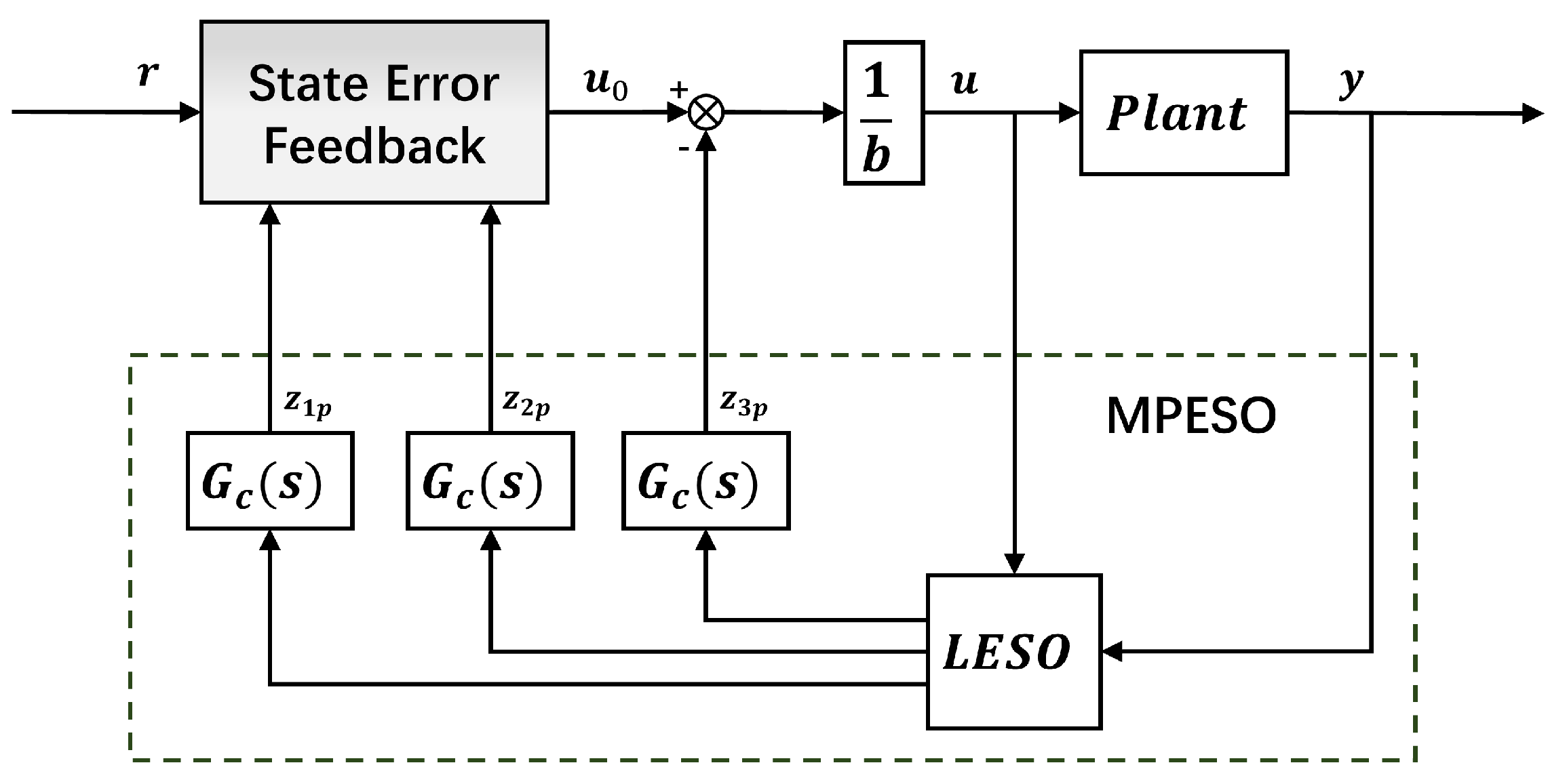
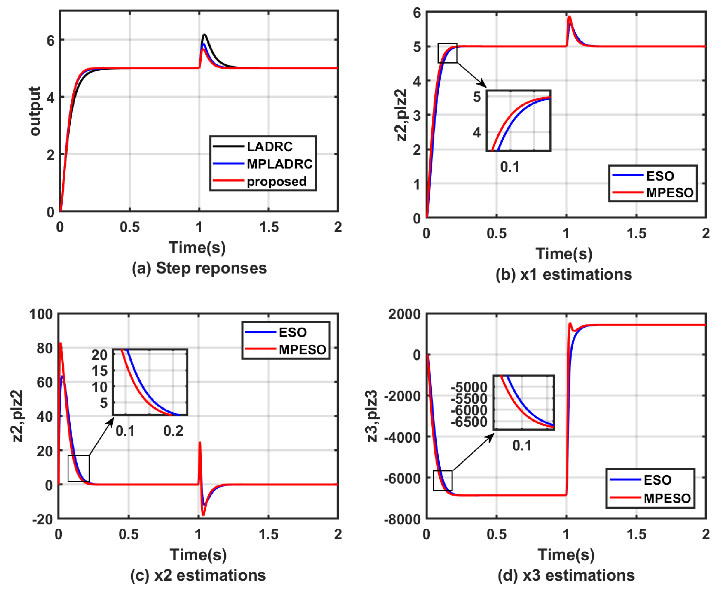
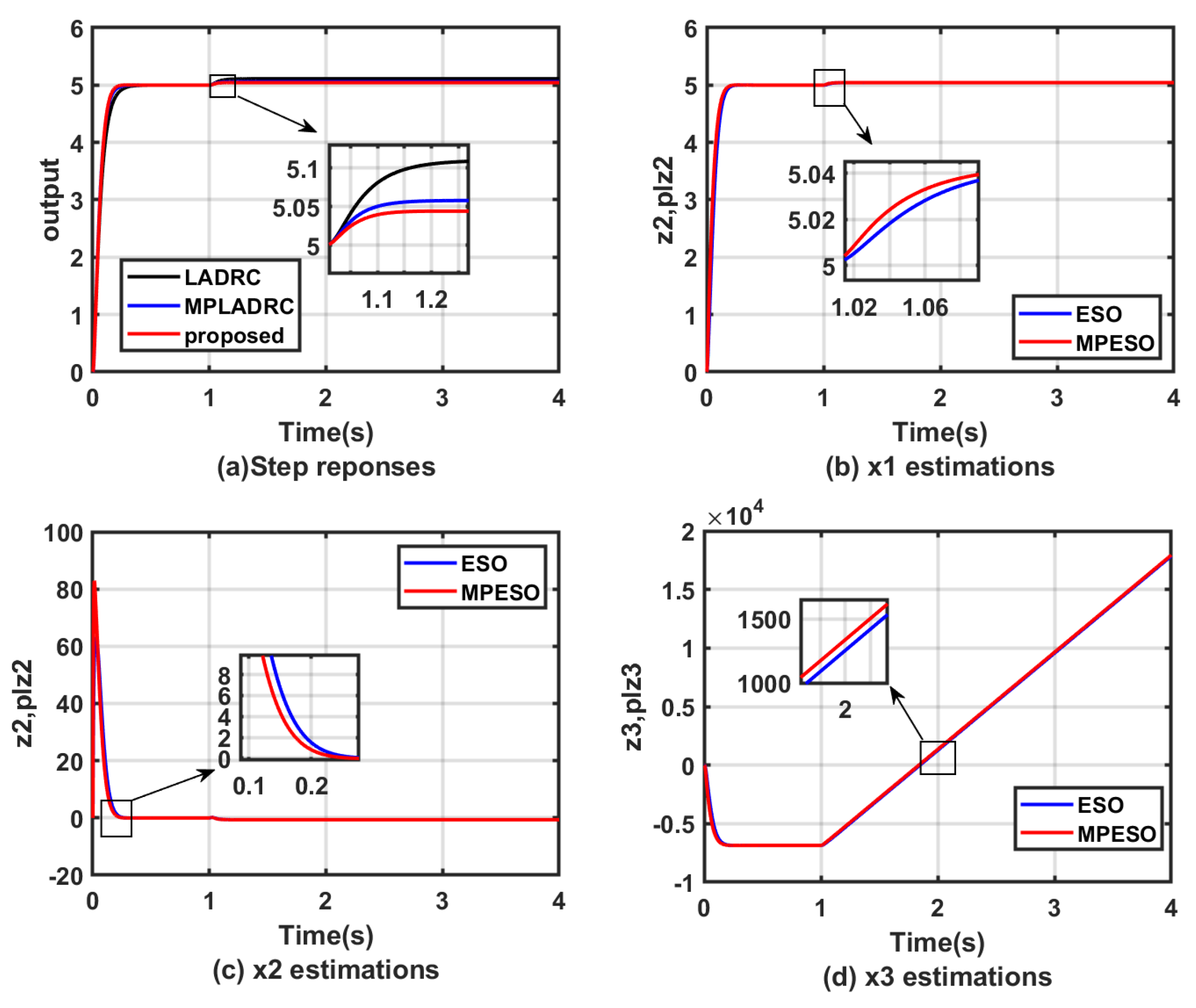
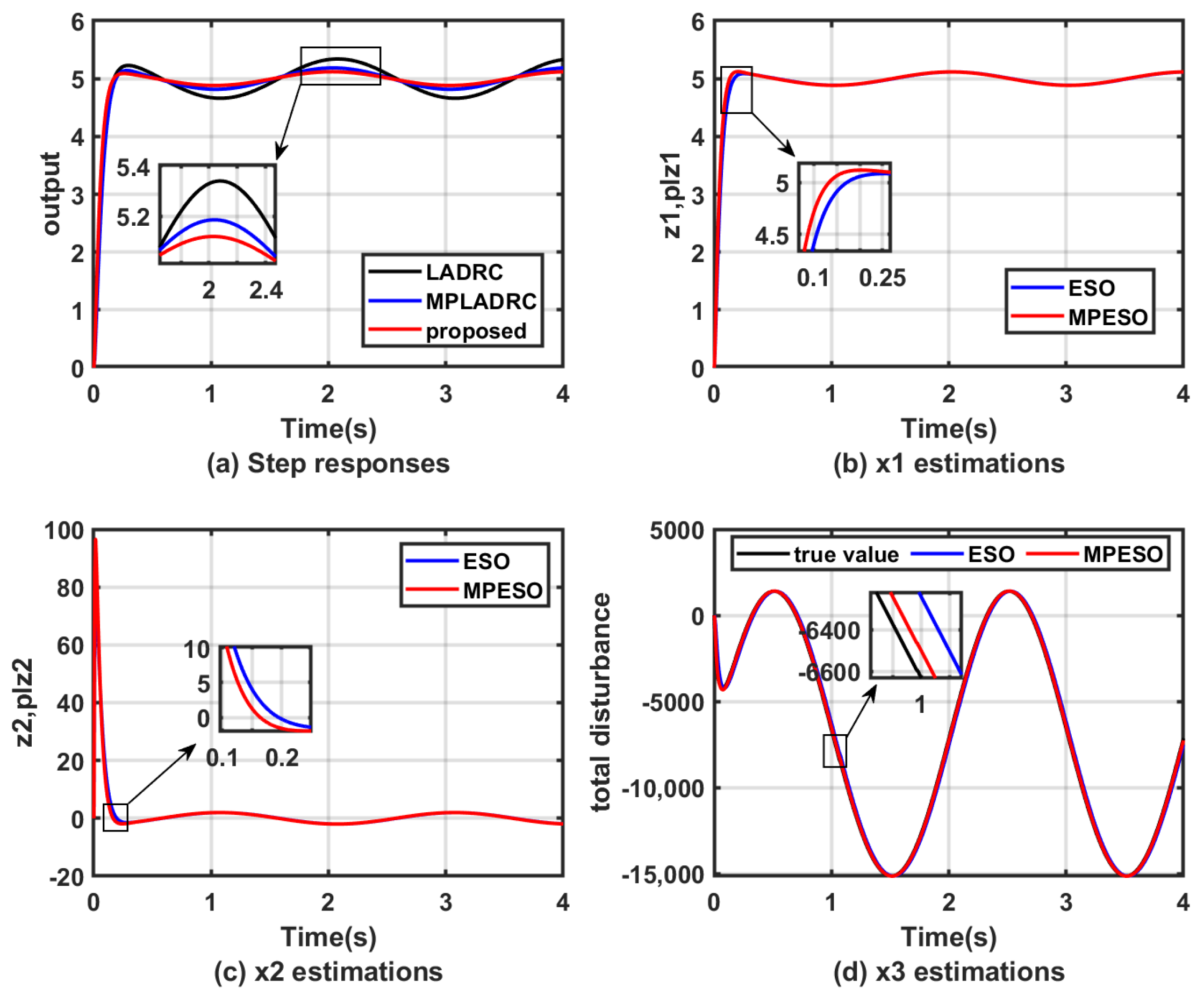
  • In the existing literature, such as [32,33], the study of the ESO does not consider the existence of lags in all observed states of the ESO, which reduces the observation accuracy of the ESO. Therefore, in this paper, a novel ESO (MPESO) is proposed, which for the first time considers and compensates for the lags of all the states of the system observed by the ESO, so that its estimation efficiency is further improved.
  • The residual uncertainty in ESO compensation of the total disturbance is a challenge, and the treatment of this uncertainty has not been adequately considered in the existing literature [41]. In this paper, this residual uncertainty is introduced into the design of the Lyapunov function for backstepping control, which is estimated and compensated to achieve cancellation of this uncertainty.
  • To demonstrate the stability of the proposed system, an equivalent control block diagram of the MPESO is presented, exploiting the small gain theorem’s original advantages, which is simple but powerful. While for special cases, equivalence may be established between small-gain conditions and Lyapunov-type conditions [42], small gain frequency domain testing is favored due to its numerical accuracy and computational efficiency.
The rest of this article is organized as follows: Section 2 states the problem formulation, explains the design procedure of the LADRC, and analyzes the phase lag of the ESO. Section 3 presents the algorithm for the MPESO and improved backstepping control law, showing that the system proposed in this paper is stable and converged. In Section 4, simulations and experimental platform experiments which verify that the proposed method is effective are described. Finally, the conclusions of the article are given in Section 5.

2. Problem Formulation

2.1. ETS Model Analysis

The ETS based on the inertial stabilization platform (ISP) has the characteristics of fast response speed and wide areas of application. It can be used for high-precision electro-optical tracking control. As shown in Figure 1, the ISP is driven by a voice coil motor and, thus, reflects the laser light emitted from the light source so it can be used to stabilize the optical path. The PSD provides the position errors between the target of the laser light and the pointing target to control the ISP. In Figure 2, the dynamic model of an ISP can be described as [15]:
U a = R a I a + K b θ ˙ C m I a = J L θ ¨ + f m θ ˙ + K m θ
where  U a I a R a C m f m K m , and  J L  are the voltage, current, resistance, back EMF coefficient, torque coefficient, viscous friction, spring stiffness of motor, and the moment of inertia, respectively. System (1) can be rewritten as
x ˙ 1 = x 2 x ˙ 2 = a 0 x 1 + a 1 x 2 + b u θ = x 1
where  a 0 = K m / J L  and  a 1 = ( R a f m + K b C m ) / J L R a b = C m / J L R a u = U a  is the control input;  θ  is the deflection angle of the motor.
Remark 1.
For inertially stabilized platforms, uncertainties within the system, such as sensor lag and unmodeled dynamics, as well as being subjected to external disturbance, severely degrade the tracking accuracy of ETSs and even cause the systems to lose the tracked target. Therefore, this paper further improves on LADRC so as to suppress the system disturbance and solve the residual uncertainty problem in a more timely way and more accurately, thus improving the tracking performance of ETSs.

2.2. Linear Active Disturbance Rejection Control

LADRC consists of a feedback control law and an extended state observer. Figure 3 presents the structure of a second-order LADRC system. Here,  u 0  and u are the outputs of the state feedback control law and the input signal of the plant, respectively;  z 1 , z 2 , z 3  are outputs of the LESO,  k 1 , k 2 , which are the parameters of the control law.
Consider a second-order plant described as
θ ¨ = b u + f 1 ( θ , w , t ) f 1 ( θ , w , t ) = a 1 θ ˙ + a 0 θ + f ( w , t )
where  a 1 , a 0 , and b are system parameters, the external disturbance is w, and  f 1  is the total disturbance.
Assumption 1.
For the above system, if the total disturbance  f 1  is bounded, there exists a constant  D *  which is satisfied by:
D * > s u p | a 1 θ ˙ + a 0 θ + f ( w , t ) |
Assumption 1 is reasonable due to the inherent physical constraints on variations in the motor states in practical control scenarios; even for phenomena occurring over very short intervals, the characteristics of the motor can be regarded as a ramp. In summary, the total disturbances can be considered to satisfy the bounded conditions in the physical realization.
Let  X = [ x 1 , x 2 , x 3 ] T x 1 = y , x 2 = y ˙ , x 3 = f 1 ; then, system (3) can be written as a state space form as follows:
X ˙ = A X + B u + E h y = C X + D u ,
where
A = 0 1 0 0 0 1 0 0 0 , B = 0 b 0 , E = 0 0 1 , C = 1 0 0 , D = 0 .
An LESO is used to estimate the state in the form of
Z ˙ = A Z + B u + L ( x 1 y ^ ) y ^ = C Z ,
where  Z = [ z 1 , z 2 , z 3 ] T  and  L = [ β 1 , β 2 , β 3 ]  are the observed state vector and the gain of the LESO, respectively. The bandwidth parameterization method [23] is employed to select the gain L, which gives  β 1 = 3 ω o , β 2 = 3 ω o 2 , a n d   β 3 = ω o 3 .

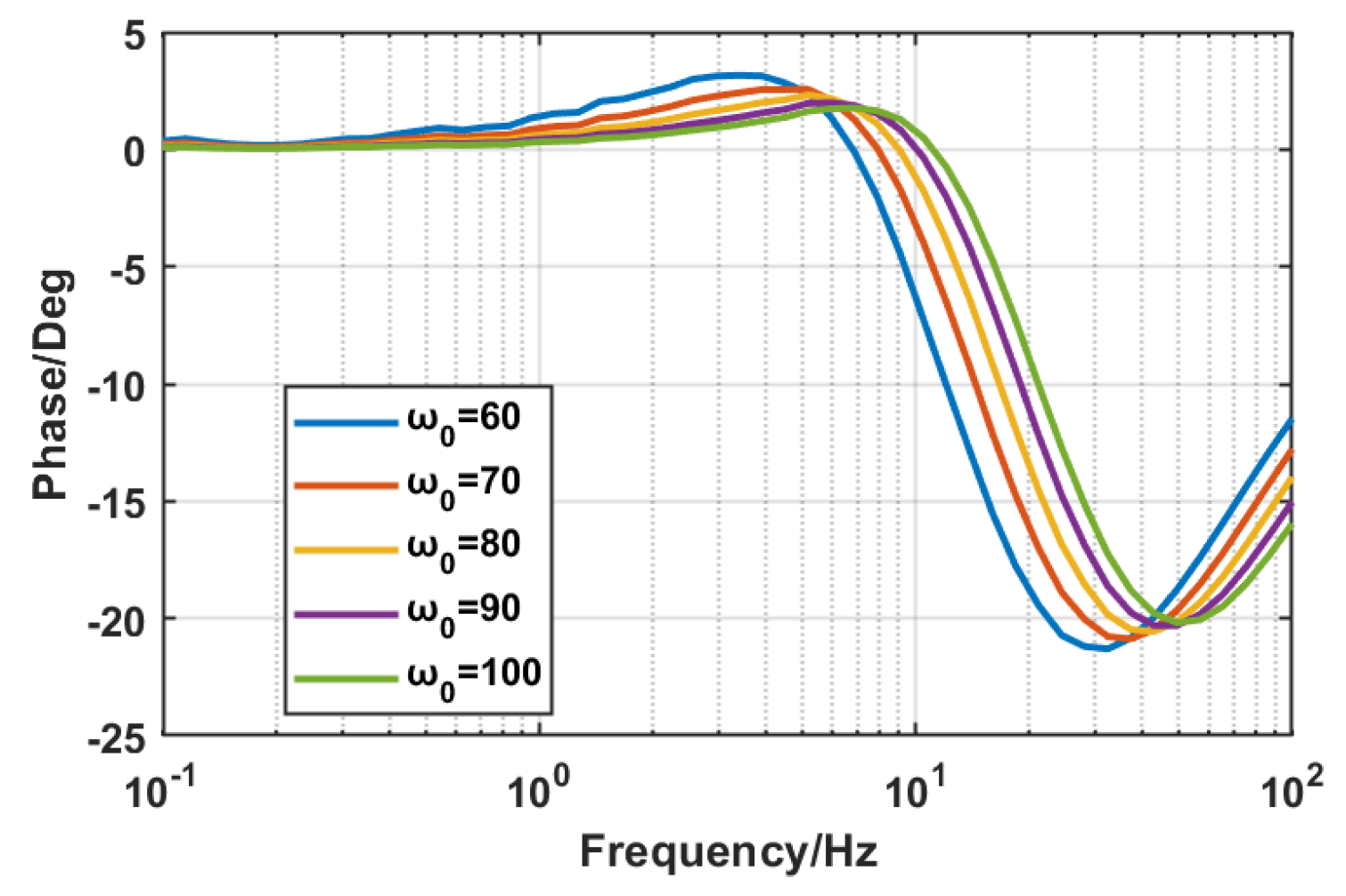
2.3. Phase Lag Analysis of the Conventional LESO

By taking the Laplace transform of the state-space realization (7), we have
s z 1 = z 2 + β 1 ( y z 1 ) s z 2 = b 0 u + z 3 + β 2 ( y z 1 ) s z 3 = β 3 ( y z 1 )
According to (8), we obtain the phase-frequency characteristic curves between the actual and observed values of each state observed by the ESO, as shown in Figure 4, Figure 5 and Figure 6.
Remark 2.
It can be seen that there is a phase lag caused by the observer itself when the ESO observes all the states of the system in the mid-frequency band from Figure 4 to Figure 6. It can also be found through (8) that this error exists on each output channel of the ESO.
When there is a lag in the ESO, it reduces the disturbance rejection capability of the controller since the total disturbance cannot be compensated in time. The tracking accuracy of the system is also further degraded due to the lag in the system states involved in the system state feedback.

3. Design of the MPESO and Control Law

This section first provides the design algorithm of the MPESO. Next, an improved backstepping control law is adopted to implement the state feedback control law of the system. Then, it is proved that the system applying the control method proposed in this paper is convergent and stable.

3.1. MPESO

In order to compensate for the phase lag that occurs when the ESO estimates the individual states of the system, the phase advance network is combined with the ESO. In the framework of the MPESO, the observed states of the ESO are treated as the object to be advanced, and the output of the phase advance network  ( z 1 p , z 2 p , z 3 p )  is the input of the feedback control law and the disturbance compensation.
The output transfer function of the MPESO is
z 1 p = z 1 1 + T s 1 + a T s z 2 p = z 2 1 + T s 1 + a T s z 3 p = z 3 1 + T s 1 + a T s
and the transfer function of the phase advance network is
G c ( s ) = 1 + a T s 1 + T s ,
where  a ( > 1 )  is the adjustable parameter and T is the time constant.
Remark 3.
According to the logarithmic frequency characteristics of this transfer function, the advance network has a significant differentiation effect for input signals with frequencies between  1 / ( a T )  and  1 / T . Within this frequency range, the phase of the output signal of the advanced network is ahead of the phase of the input signal, achieving the function of compensating for the signal phase lag.
In order to conduct a convergence analysis on the MPESO estimation error, since the MPESO is a combination of the ESO and the phase advance network, we regard the MPESO as an overall state equation and substitute (10) into (8)
s z 1 p 1 + a T s 1 + T s = z 2 p 1 + a T s 1 + T s + β 1 ( y z 1 p 1 + a T s 1 + T s ) s z 2 p 1 + a T s 1 + T s = b 0 u + z 3 p 1 + a T s 1 + T s + β 2 ( y z 1 p 1 + a T s 1 + T s ) s z 3 p 1 + a T s 1 + T s = β 3 ( y z 1 p 1 + a T s 1 + T s )
Simplifying (11)
s z 1 p = z 2 p + β 1 ( y 1 + T s 1 + a T s z 1 p ) s z 2 p = b 0 u 1 + T s 1 + a T s + z 3 p + β 2 ( y 1 + T s 1 + a T s z 1 p ) s z 3 p = β 3 ( y 1 + T s 1 + a T s z 1 p )
We can assume that  y ¯ = y ( 1 + T s 1 + a T s ) u ¯ = u ( 1 + T s 1 + a T s ) ; then, (12) can be written as
s z 1 p = z 2 p + β 1 ( y ¯ z 1 p ) s z 2 p = b 0 u ¯ + z 3 p + β 2 ( y ¯ z 1 p ) s z 3 p = β 3 ( y ¯ z 1 p ) .
Taking the inverse Laplace transform of (13), it can be written as
z ˙ 1 p z ˙ 2 p z ˙ 1 p = β 1 1 0 β 2 0 0 β 3 0 0 z 1 p z 2 p z 3 p + 0 β 1 b 0 β 2 0 β 3 u ˇ y ˇ ,
where  u ˇ , y ˇ  are the forms after the inverse Laplace transform of  u ¯ , y ¯ , respectively.
The characteristic polynomial of (12) is
λ ( s ) = s 3 + β 1 s 2 + β 2 s + β 3
Pole-placement of the characteristic polynomial of the MPESO using the observer bandwidth
s 3 + β 1 s 2 + β 2 s + β 3 = ( s + ω o ) 3
The corresponding parameters are expressed as
β 1 = 3 ω o β 2 = 3 ω o 2 β 3 = ω o 3
Remark 4.
Equations (7) and (14) illustrate that the characteristic equation of the modified system, resulting from the incorporation of the phase advance network into the ESO, remains unaltered. Utilizing the bandwidth method as outlined in reference [23], the poles of the three parameters, denoted by the observer bandwidth, are configured. Adjusting the observer bandwidth becomes crucial to guarantee a negative pole in the characteristic equation of (12), thereby facilitating the convergence of the observation error for the MPESO.
As shown in Figure 7, the equivalent control block diagram of the MPESO in the form of the transfer function is given, where  G p ( s )  is the actual controlled plant,  G n ( s )  is the nominal model of the controlled plant,  Q ( s )  is the phase advance network, and  Q ( s )  is the equivalent low-pass filter form extracted from the extended state observer,  Q ( s ) = β 3 s 3 + β 1 s 2 + β 2 s + β 3 .
Theorem 1.
The introduction of the phase advance network on the output channels of the ESO can effectively improve the disturbance rejection capability of the ESO system.
Proof. 
For the MPESO, its disturbance transfer function can be expressed as
G d , y ( s ) = y ( s ) d ( s ) = b ( 1 Q ( s ) G c ( s ) ) G p ( s ) G n ( s ) b G n ( s ) + Q ( s ) G c ( s ) ( G p ( s ) b G n ( s ) ) = G p ( s ) 1 + G p ( s ) Q ( s ) G c ( s ) b ( 1 G c ( s ) Q ( s ) ) G n ( s )
in the low-frequency band. It can be approximately considered that  G p ( s ) = G n ( s ) ; then, (18) can be rewritten as
G d , y ( s ) = G p ( s ) 1 + 1 b ( 1 1 Q ( s ) G c ( s ) 1 ) .
In the same way, the disturbance transfer function of the LESO is
G d , y ( s ) ´ = G p ( s ) 1 + 1 b ( 1 1 Q ( s ) 1 )
Since  G c ( s ) = 1 + T s 1 + a T s  and  0 < a < 1 , we obtain  G c ( s ) > 1 . Therefore, it is not difficult to derive that  | G d , y ( s ) | < | G d , y ( s ) | ´ , which means that when the plant is approximately restored to the nominal model, the amplitude of the closed-loop transfer function from the disturbance to the desired output becomes smaller, and the disturbance rejection performance of the MPESO system is enhanced. □

3.2. Improved Backstepping Control Method Design

In order to deal with the phenomenon of residual error in the series type of integrator, an improved backstepping control law based on the Lyapunov stability is designed, which treats the residual error as uncertainty and offsets it. Combining it with the MPESO, the characteristics of the integrator series type can be effectively utilized, thus reducing its dependence on model information.
The control block diagram of the improved backstepping and MPADRC method is given in Figure 8.
Where  r , y , and u are the input, output, and control signals of the system.
The integrator series for the second-order system is
x ˙ 1 = x 2 x ˙ 2 = x 3 x 1 = y x 2 = y ˙
Although the MPESO can achieve the suppression of disturbances as well as nonlinearities, in practical applications, due to the limitation of actual application scenarios and hardware equipment, there will always be a deviation between the total disturbances observed by the MPESO and the real total disturbances, which results in the total disturbances not being completely eliminated. There is a residual uncertainty when the system is reduced to the integrator series type (20), which results in the degradation of the system’s tracking accuracy.
Consider the residual error in the integrator series type as  δ T = z 3 p f 1 ( θ , w , t ) . The system after total disturbance compensation can be written as
y ¨ = u 0 + δ T .
In order to deal with this residual uncertainty so that the tracking accuracy of the system can be further improved, we regard the residual uncertainty in the integrator series-type system as the nonlinearity of the system and suppress it using an improved backstepping control method.
In the MPESO structure, the system state variables can be rewritten as
x 1 = z 1 p x 2 = z 2 p
Theorem 2.
For the second-order system, considering the residual uncertainty present in the nominal system after ESO reduction, the state feedback control law can be designed as
u 0 = k 1 e 1 2 + x ˙ 2 d e 1 k 2 e 2 + δ T ^ .
Proof. 
Define the signal that the control system expects to track as  x 1 d ; then, the tracking error is  e 1 = x 1 x 1 d .
Choose the Lyapunov function as
V 1 = 1 2 e 1 2
Differentiate (25)
V ˙ 1 = e 1 e ˙ 1 = e 1 ( x ˙ 1 x ˙ 1 d )
According to the second method of Lyapunov, for the error  e 1  to converge and the system to reach stability,  V ˙ 1  should be negative definite. That is
e ˙ 1 = x ˙ 1 x ˙ 1 d k 1 e 1
We can have
x ˙ 1 = x 2 ( x ˙ 1 d k 1 e 1 ) .
If  x 2  can converge to  x ˙ 1 d k 1 e 1 , then the system will be stable. So, it is worthwhile to set the approximation of  x 2  to be  x 2 d = x ˙ 1 d k 1 e 1  and the error of both to be  e 2 = x 2 x 2 d . For the whole system, the Lyapunov function is again designed to make  e 1 , e 2  converge at the same time so that the system reaches stability
V 2 = 1 2 ( e 1 2 + e 2 2 )
Differentiate (29)
V ˙ 2 = e 1 e ˙ 1 + e 2 e ˙ 2
Combining the above equations, we obtain
V ˙ 2 = k 1 e 1 2 + e 2 ( u 0 + δ T x ˙ 2 d + e 1 ) .
Let the estimate of  δ T  be  δ T ^  with error  δ T e = δ T ^ δ T . To ensure that the error converges, the control law can be designed as
u 0 = k 1 e 1 2 + x ˙ 2 d e 1 k 2 e 2 + δ T ^ .
In order for  δ T e  to converge, design  δ T ^ ˙  as  δ T ^ ˙ = γ e 2 . □
Remark 5.
For  δ T ^ , we can adjust the relevant parameters to approximate the true value  δ T . Even if we are unable to accurately model  δ T , we can still use this law to achieve an adaptive effect for  δ T . The form of this estimate will be given later.
Remark 6.
Combining the improved backstepping control law with the MPESO solves the problem of the residual error that occurs when the original system cannot be reduced by a perfect reduction of the integrator series and also makes full use of the features of the ESO to reduce the dependence of the backstepping control law on the model.

3.3. Stability Analysis

In accordance with the separation theorem, the development of the state feedback control law and the design of the observer can be conducted autonomously in the context of an output feedback system utilizing a state observer. The stability analysis for the closed-loop system can be bifurcated into two distinct components. Firstly, the stability of the state observer, denoted as the MPESO, must be ensured. Secondly, the stability of the backstepping control law, formulated based on the Lyapunov stability principle, needs to be established.

3.3.1. Analysis for the MPESO

Lemma 1.
For the system in this paper, when the phase advanced network  G c ( s )  and filter  Q ( s )  satisfy the following constraints:
Q ( s ) G c ( s ) Δ ( s ) b ( 1 + Q ( s ) G c ( s ) ) + Q ( s ) G c ( s ) < 1 ,
the MPESO is stable.
Proof. 
With Figure 7, the transfer function between  u 0  and y can be written as
G u 0 , y ( s ) = y ( s ) u 0 ( s ) = G n ( s ) G p ( s ) b G n ( s ) + Q ( s ) G c ( s ) ( G p ( s ) b G n ( s ) )
Suppose the multiplicative uncertainty of the plant is expressed as
G p ( s ) = G n ( s ) ( 1 + Δ ( s ) ) .
In the low-frequency band, since  G P ( s ) = G n ( s ) , the complementary sensitivity function of the MPESO is
T = Q ( s ) G c ( s ) b ( 1 + Q ( s ) G c ( s ) ) + Q ( s ) G c ( s )
According to the robust stability condition, the system is stable when the following conditions are satisfied:
Q ( s ) G c ( s ) Δ ( s ) b ( 1 + Q ( s ) G c ( s ) ) + Q ( s ) G c ( s ) < 1

3.3.2. Analysis for the Control Law

Lemma 2.
Consider the residual uncertainty  δ T ^ ˙  in the nominal model of the system; when the following conditions are satisfied:
δ T ^ ˙ = γ e 2
the backstepping control law (32) is stable.
Proof. 
The Lyapunov function is chosen as
V 3 = 1 2 e 1 2 + 1 2 e 2 2 + 1 2 γ e 3 2
Differentiate (39)
V ˙ 3 = k 1 e 1 2 k 2 e 2 2 + δ T ¯ ( e 2 γ 1 δ T ^ ˙ )
If
δ T ^ ˙ = γ e 2
we have
V ˙ 3 = k 1 e 1 2 k 2 e 2 2
The parameters are set to the following ranges:
k 1 > 0 k 2 > 0 γ > 0
Then,
V ˙ 3 = k 1 e 1 2 k 2 e 2 2 < 0 .
According to the second method of Lyapunov (39) is positive definite, and (42) is negative definite, then the control law is asymptotically stable. It has been proved before that the MPESO is convergent and robustly stable, so combined with the separation principle of the observer, it can be guaranteed that the whole closed-loop system is stable. □

3.4. Parameter Selection Rules

First, the parameters T and a in the transfer function (10) of the phase advance network need to be adapted to the stable condition (33). Then, the estimation’s precision, the system stability, and the response dynamics should be taken into account. The parameter tuning rules are summarized as follows:
  • In the context of the ESO, the parameter  ω o  is considered, and there is a need to maximize its value to enhance the convergence speed of the ESO observation error. However, an excessively large  ω o  may amplify high-frequency noise in the system, leading to instability. Therefore, the selection of  ω o  requires a careful balance between disturbance suppression and noise amplification;
  • Then,  k 1 k 2 , and  g a m m a  are tuned to achieve a balance between overshoot and rapid response while ensuring stability.
  • For the parameters a and T, a nuanced adjustment is essential based on the system’s frequency response characteristics to simultaneously enhance the phase margin and meet the requirements for dynamic performance. Evaluating the closed-loop system response is required to ensure the avoidance of instability or other adverse characteristics.
Finally, the parameters of the tests described in Section 4 are configured as given in Table 1 according to the above rules.

4. Simulation and Experimental Verification

Specific simulations and experimental verification were carried out in the inertial stabilization platform (ISP) of the ETS. Figure 9 presents the experimental platform, which is mainly a motion platform driven by a voice coil motor. The laser emitted by the light source on the ISP is reflected by a mirror and enters the position sensitive detector (PSD), which is a device capable of detecting the photoelectric position. The control objective of the ISP is to stabilize the laser at the center of the PSD imaging panel. The PSD outputs the distance between the laser point position and the center of the imaging panel as the error signal of the position closed loop.
A dynamic signal analyzer was used to generate a sinusoidal signal of constant amplitude and varying frequency in the range of 0.1 Hz–100 Hz to drive the voice coil motor. The PSD output signal was captured in an open loop. Numerical fitting was performed based on the sweep frequency results. Figure 10 shows the numerical fitting results of (45).
G ( s ) = Y ( s ) U ( s ) = 829.9 s 2 + 17.83 s + 1371.7 .

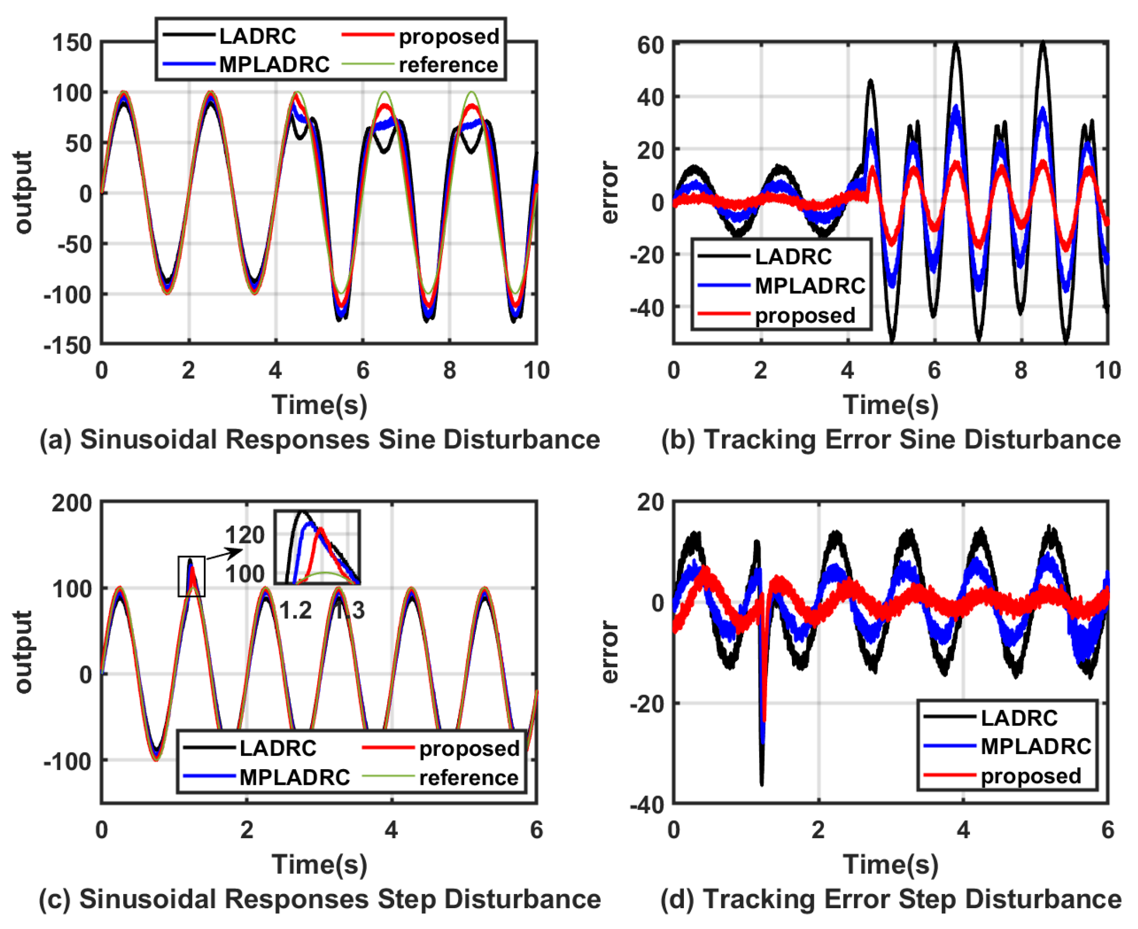
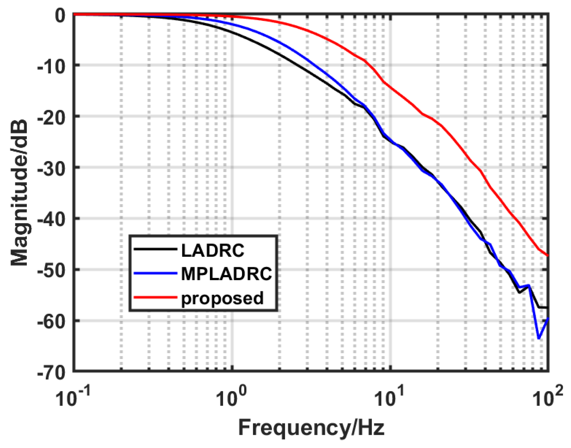
4.1. Simulation Verification

The parameter settings [23,32] of LADRC, MPADRC, and the proposed system were used in the simulation. The values of the specific controller parameters are given in Table 1.
Firstly, simulation verifications were carried out to illustrate the enhancement brought by the proposed method in this paper to the tracking performance of the ETS. Specifically, (45) is taken as the controlled plant of the system. In order to simulate the immunity performance of the system when it is subjected to different types of disturbances, disturbance signals in step, ramp, and sinusoidal form are applied to the controlled plant. The multi-channel phase-compensated ADRC method (MPADRC) and the MPADRC method incorporating a backstepping control strategy (proposed) are also compared with LADRC.
We can observe from Figure 11, Figure 12 and Figure 13 that the MPADRC method and the proposed method that combines MPADRC with improved backstepping control show better disturbance rejection performance than the conventional LADRC under disturbance. The convergence speed of the individual states of the system observed by the ESO is improved after being compensated by the phase advanced network.
In addition, to further demonstrate the observational effectiveness of the MPESO, the observed values of the MPESO and ESO methods for the total disturbance are compared with the true values of the total disturbance. From Figure 11d–Figure 13d, it can be seen that the observed values of the MPESO for the total disturbance are much closer to the true value, which further proves the validity of the method proposed in this paper.
To quantitatively describe the performance of the proposed method, the tracking performance evaluation metrics ITAE and ITSE (46) were used.
I T A E = t | r ( t ) y ( t ) | d t I T S E = t ( r ( t ) y ( t ) ) 2 d t .
It is shown in Table 2 and Table 3 that compared to LADRC, the MPLADRC method exhibits better performance, i.e., the corresponding ITAE and ITSE are smaller, which suggests that the output signal of the system is closer to the input signal. In addition, the data in the table show that the proposed method provides a further improvement in the control performance of the system.

4.2. Experimental Verification

For the time domain experiments, comparisons of the step responses results under step disturbance and sinusoidal disturbances are shown in Figure 14, respectively. Figure 15 shows the drive input signals of the controlled object. The amplitudes of the step response and the step disturbances are 50 and 100, respectively, and the frequencies of the sinusoidal disturbances are 0.5 Hz, 1 Hz, and 2 Hz, respectively. The experimental results show that the proposed method, which combines MPADRC with improved backstepping control, has a much smaller peak and can converge the system to the specified position more quickly.
The frequency domain results are shown in Figure 16. Compared with LADRC, both MPADRC and the proposed method can suppress more perturbations in the middle- and low-frequency bands. It can also be seen that the combination of the improved backstepping method further improves the perturbation suppression performance of MPADRC.
Figure 17 shows the tracking performance of the system for sinusoidal signals when subjected to different disturbance signals. The disturbance input signals are a step signal with an amplitude of 500 and a sinusoidal signal with an amplitude of 500 and a frequency of 1 Hz, respectively.
Table 4 and Table 5 quantitatively describe the control performance corresponding to the different control methods in the experiments using the ITAE. In them, the calculated results are scaled equally for ease of description. The results further confirm the validity of the method proposed in this paper.
Figure 18, Figure 19 and Figure 20 substantiate the efficacy of the controller in tracking sinusoidal signals, both in the temporal and frequency domains, respectively. The outcomes demonstrate that the methodology proposed in this study exhibits superior performance with reduced tracking errors and an expanded tracking bandwidth.

5. Summary and Conclusions

In this paper, a multi-channel phase-compensated ADRC design scheme incorporating an improved backstepping method is proposed to compensate for the phase lag that exists when the ESO estimates all the states of the system and enhances the disturbance rejection capability. Meanwhile, a state feedback control law is designed based on the Lyapunov stability principle, which eliminates the participation uncertainty and, thus, improves the stable tracking capability of the system. Simulation and experimental results obtained show that both the MPADRC method and the MPADRC method incorporating the improved backstepping control strategy can further enhance the disturbance rejection capability of the controller compared with the LADRC, regardless of whether a disturbance is applied to the system in the form of a step or a sinusoidal signal.
Efforts to enhance compensation for the phase lag in response to extended state observer (ESO) bandwidth variations warrant further investigation. Future research could explore advanced phase correction methods, including fractional-order phase override networks, for more precise mitigation of observation lag in the ESO. This has the potential to advance compensation strategies in control systems.

Author Contributions

Theoretical analysis: S.Z. and J.L.; designing experiments and analyzing data: S.Z. and H.W.; conducting simulations: S.Z. and J.L.; writing the paper: S.Z.; revising the paper: J.D. and Y.M. All authors have read and agreed to the published version of the manuscript.

Funding

This work was supported by the Special Research Assistant Program, Chinese Academy of Sciences, China (Grant No. E329691C21) and the Natural Science Foundation of Sichuan Province for Youths, China (Grant No. 24NSFSC3777).

Institutional Review Board Statement

Not applicable.

Informed Consent Statement

Not applicable.

Data Availability Statement

Data are contained within the article.

Conflicts of Interest

The authors declare no conflicts of interest.

References

  1. Tao, T.; Jiaguang, M.; Hongbin, C.; Chengyu, F.; Hu, Y.; Ge, R.; Wenshu, Y.; Bo, Q.; Lei, C.; Mengwei, Z.; et al. A review on precision control methodologies for optical-electric tracking control system. Opto-Electron. Eng. 2020, 47, 200315. [Google Scholar]
  2. Kaidong, Y.; De’en, W.; Ying, Y.; Dangpeng, X.; Fang, W.; Hao, L. Inertial stabilization technology in optical-electric tracking system. High Power Laser Part. Beams 2022, 34, 081007. [Google Scholar]
  3. Deng, J.; Xue, W.; Liang, W.; Zhou, X.; Mao, Y. On adjustable and lossless suppression to disturbances and uncertainties for nonminimum-phase laser pointing system. ISA Trans. 2023, 136, 727–741. [Google Scholar] [CrossRef] [PubMed]
  4. Zhijun, L.; Yao, M.; Bo, Q.; Xi, Z.; Qiong, L.; Qian, Z. Research on control technology of single detection based on position correction in quantum optical communication. Opto-Electron. Eng. 2022, 49, 210311. [Google Scholar]
  5. Xu, C.; Huang, D.; Liu, J. Target Location of Unmanned Aerial Vehicles Based on the Electro-Optical Stabilization and Tracking Platform. Measurement 2019, 147, 106848. [Google Scholar] [CrossRef]
  6. Bi, Z.; Tian, Z.; Luo, T.; Fu, S. Study on Shipborne Video Electro-Optical Tracking System Based on FPGA. In Proceedings of the 5th International Conference on Electrical Engineering and Automatic Control, Khenchela, Algeria, 15–17 November 2016; pp. 521–529. [Google Scholar]
  7. Boroson, D.M.; Robinson, B.S.; Burianek, D.A.; Murphy, D.V.; Biswas, A. Overview and status of the Lunar Laser Communications Demonstration. In Proceedings of the SPIE—The International Society for Optical Engineering, Barcelona, Spain, 26–29 November 2012; Volume 8246, p. 7. [Google Scholar]
  8. Tang, T.; Qi, B.; Yang, T. Youla–Kucera Parameterization-Based Optimally Closed-Loop Control for Tip–Tilt Compensation. IEEE Sensors J. 2018, 18, 6154–6160. [Google Scholar] [CrossRef]
  9. Chaudhary, H.; Khatoon, S.; Singh, R.; Pandey, A. Fast steering mirror for optical fine pointing applications: A review paper applications: A review paper. In Proceedings of the 2018 3rd International Innovative Applications of Computational Intelligence on Power, Energy and Controls with their Impact on Humanity (CIPECH), Ghaziabad, India, 1–2 November 2018; pp. 1–5. [Google Scholar]
  10. Fan, Y.; He, Y.; Tan, U.X. Real-Time Compensation System via Gyroscope and Fast Steering Mirror for Wide-Bandwidth Multiple-Frequency Vehicle Disturbance. IEEE/ASME Trans. Mechatron. 2020, 25, 650–660. [Google Scholar] [CrossRef]
  11. Wang, L.; Liu, X.; Wang, C. Modeling and design of fast steering mirror in image motion compensation for backscanning step and stare imaging systems. Opt. Eng. 2019, 58, 103105. [Google Scholar] [CrossRef]
  12. Deng, J.; Xue, W.; Zhou, X.; Mao, Y. On disturbance rejection control for inertial stabilization of long-distance laser positioning with movable platform. Meas. Control 2020, 53, 1203–1217. [Google Scholar] [CrossRef]
  13. Nie, K.; Xue, W.; Zhang, C.; Mao, Y. Disturbance Observer-based Repetitive Control with Application to Optoelectronic Precision Positioning System. J. Frankl. Inst. 2021, 358, 8443–8469. [Google Scholar] [CrossRef]
  14. Tian, J.; Yang, W.; Peng, Z.; Tang, T. Inertial sensor-based multiloop control of fast steering mirror for line of sight stabilization. Opt. Eng. 2016, 55, 111602. [Google Scholar] [CrossRef]
  15. Zhang, B.; Nie, K.; Chen, X.; Mao, Y. Development of Sliding Mode Controller Based on Internal Model Controller for Higher Precision Electro-Optical Tracking System. Actuators 2022, 11, 16. [Google Scholar] [CrossRef]
  16. Wei, Q.; Wu, Z.; Zhou, Y.; Ke, D.; Zhang, D. Active Disturbance-Rejection Controller (ADRC)-Based Torque Control for a Pneumatic Rotary Actuator with Positional Interference. Actuators 2024, 13, 66. [Google Scholar] [CrossRef]
  17. Zhou, W.; Guo, S.; Guo, J.; Meng, F.; Chen, Z. ADRC-Based Control Method for the Vascular Intervention Master-Slave Surgical Robotic System. Micromachines 2021, 12, 1439. [Google Scholar] [CrossRef] [PubMed]
  18. Zhang, P.; Shi, Z.; Yu, B. Research on Friction Compensation Method of Electromechanical Actuator Based on Improved Active Disturbance Rejection Control. Actuators 2023, 12, 445. [Google Scholar] [CrossRef]
  19. Zhu, H.; Weng, F.; Makeximu; Li, D.; Zhu, M. Active control of combustion oscillation with active disturbance rejection control (ADRC) method. J. Sound Vib. 2022, 540, 117245. [Google Scholar] [CrossRef]
  20. Qi, X.; Li, J.; Xia, Y.; Wan, H. On stability for sampled-data nonlinear ADRC-based control system with application to the ball-beam problem. J. Frankl. Inst. 2018, 355, 8537–8553. [Google Scholar] [CrossRef]
  21. Han, J. From PID to Active Disturbance Rejection Control. IEEE Trans. Ind. Electron. 2009, 56, 900–906. [Google Scholar] [CrossRef]
  22. Han, J. Extended state observer for a class of uncertain plants. Control Decis. 1995, 10, 85–88. [Google Scholar]
  23. Gao, Z. Scaling and Parameterization Based Controller Tuning. In Proceedings of the American Control Conference, Denver, CO, USA, 4–6 June 2003. [Google Scholar]
  24. Zhou, X.; Li, X. Trajectory Tracking Control for Electro-Optical Tracking System Using ESO Based Fractional-Order Sliding Mode Control. IEEE Access 2021, 9, 45891–45902. [Google Scholar] [CrossRef]
  25. Hu, X.; Han, S.; Liu, Y.; Wang, H. Two-Axis Optoelectronic Stabilized Platform Based on Active Disturbance Rejection Controller with LuGre Friction Model. Electronics 2023, 12, 1261. [Google Scholar] [CrossRef]
  26. Zachi, A.R.; Correia, C.A.M.; A. Filho, J.L.; Gouvêa, J.A. Robust disturbance rejection controller for systems with uncertain parameters. IET Control Theory Appl. 2019, 13, 1995–2007. [Google Scholar] [CrossRef]
  27. Teixeira, A.; Gouvea, J.A.; Zachi, A.R.L.; Rodrigues, V.H.P.; Oliveira, T.R. Monitoring function-based active disturbance rejection control for uncertain systems with unknown control directions. Adv. Control Appl. Eng. Ind. Syst. 2021, 3, e66. [Google Scholar] [CrossRef]
  28. Gouvêa, J.A.; Fernandes, L.M.; Pinto, M.F.; Zachi, A.R. Variant ADRC design paradigm for controlling uncertain dynamical systems. Eur. J. Control 2023, 72, 100822. [Google Scholar] [CrossRef]
  29. Gouvêa, J.A.; Raptopoulos, L.S.C.; Pinto, M.F.; Díaz, E.Y.V.; Dutra, M.S.; Sousa, L.C.d.; Batista, V.M.O.; Zachi, A.R.L. Attitude Control of Ornithopter Wing by Using a MIMO Active Disturbance Rejection Strategy. Sensors 2023, 23, 6602. [Google Scholar] [CrossRef] [PubMed]
  30. Dong, Z.; Sun, Z.; Sun, H.; Wang, W.; Mei, X. A Novel Control Method for Permanent Magnet Synchronous Linear Motor Based on Model Predictive Control and Extended State Observer. Actuators 2024, 13, 34. [Google Scholar] [CrossRef]
  31. Liao, L.; Gao, L.; Ngwa, M.; Zhang, D.; Du, J.; Li, B. Adaptive Super-Twisting Sliding Mode Control of Underwater Mechanical Leg with Extended State Observer. Actuators 2023, 12, 373. [Google Scholar] [CrossRef]
  32. Wei, W.; Zhang, Z.; Zuo, M. Phase leading active disturbance rejection control for a nanopositioning stage. ISA Trans. 2021, 116, 218–231. [Google Scholar] [CrossRef]
  33. Dong, L.; Chen, Z.; Sun, M.; Sun, Q. Phase compensation active disturbance rejection control for shimmy vibration with magnetorheological damper of aircraft. Expert Syst. Appl. 2023, 213, 119126. [Google Scholar] [CrossRef]
  34. Du, Y.; Cao, W.; She, J. Analysis and design of active disturbance rejection control with an improved extended state observer for systems with measurement noise. IEEE Trans. Ind. Electron. 2022, 70, 855–865. [Google Scholar] [CrossRef]
  35. Fu, C.; Tan, W. Analysis and tuning of reduced-order active disturbance rejection control. J. Frankl. Inst. 2021, 358, 339–362. [Google Scholar] [CrossRef]
  36. Bartkowiak, P.; Pazderski, D. Position tracking control of a robotic joint using error-based ADRC with full and reduced order ESO. In Proceedings of the 2023 27th International Conference on Methods and Models in Automation and Robotics (MMAR), Miedzyzdroje, Poland, 22–25 August 2023; pp. 350–355. [Google Scholar]
  37. Doostdar, F.; Mojallali, H. An ADRC-based backstepping control design for a class of fractional-order systems. ISA Trans. 2022, 121, 140–146. [Google Scholar] [CrossRef]
  38. Li, S.; Li, H.; Wang, H.; Yang, C.; Gui, J.; Fu, R. Sliding Mode Active Disturbance Rejection Control of Permanent Magnet Synchronous Motor Based on Improved Genetic Algorithm. Actuators 2023, 12, 209. [Google Scholar] [CrossRef]
  39. Liu, J.; Gai, W.; Zhang, J.; Li, Y. Nonlinear adaptive backstepping with ESO for the quadrotor trajectory tracking control in the multiple disturbances. Int. J. Control Autom. Syst. 2019, 17, 2754–2768. [Google Scholar] [CrossRef]
  40. Patelski, R.; Pazderski, D. Parameter Identifying Disturbance Rejection Control With Asymptotic Error Convergence. IEEE Robot. Autom. Lett. 2023, 9, 1035–1042. [Google Scholar] [CrossRef]
  41. Li, J.; Zhang, L.; Luo, L.; Li, S. Extended state observer based current-constrained controller for a PMSM system in presence of disturbances: Design, analysis and experiments. Control Eng. Pract. 2023, 132, 105412. [Google Scholar] [CrossRef]
  42. Zhang, J.; Knopse, C.R.; Tsiotras, P. Stability of time-delay systems: Equivalence between Lyapunov and scaled small-gain conditions. IEEE Trans. Autom. Control 2001, 46, 482–486. [Google Scholar] [CrossRef]
Figure 1. Diagram of the inertial stabilized platform control system.
Actuators 13 00117 g001
Figure 2. Physical model structure of the controlled plant.
Actuators 13 00117 g002
Figure 3. Structure of the LADRC of the second−order system.
Actuators 13 00117 g003
Figure 4. Phase−frequency characteristic of  z 3 f 1 .
Actuators 13 00117 g004
Figure 5. Phase−frequency characteristic of  z 1 y .
Actuators 13 00117 g005
Figure 6. Phase−frequency characteristic of  z 2 y ˙ .
Actuators 13 00117 g006
Figure 7. Equivalent control block diagram of the MPESO.
Actuators 13 00117 g007
Figure 8. Block diagram of the improved backstepping and MPADRC.
Actuators 13 00117 g008
Figure 9. Experimental setup.
Actuators 13 00117 g009
Figure 10. Numerical fitting result.
Actuators 13 00117 g010
Figure 11. Simulation results for the step responses under step disturbance.
Actuators 13 00117 g011
Figure 12. Simulation results for the step responses under ramp disturbance.
Actuators 13 00117 g012
Figure 13. Simulation results for the step responses under sine disturbance.
Actuators 13 00117 g013
Figure 14. Step responses.
Actuators 13 00117 g014
Figure 15. Input of step responses.
Actuators 13 00117 g015
Figure 16. Measure Bode diagrams.
Actuators 13 00117 g016
Figure 17. Sinusoidal responses (with disturbance).
Actuators 13 00117 g017
Figure 18. Sinusoidal responses (without disturbance).
Actuators 13 00117 g018
Figure 19. Input of sinusoidal responses.
Actuators 13 00117 g019
Figure 20. Measure Bode diagrams.
Actuators 13 00117 g020
Table 1. Parameters of the controllers.
Controllersb   ω c   ω 0 aT   k 1   k 2   γ
LADRC83040 Hz100 Hz-----
MPLADRC83040 Hz100 Hz0.80.1---
Proposed83040 Hz100 Hz0.80.1404020
Table 2. ITAE for different controllers under step response.
ControllersStep DisturbanceSine DisturbanceRamp Disturbance
LADRC32.94351.10175.63
MPLADRC27.26292.17144.32
Proposed21.30227.26110.81
Table 3. ITSE for different controllers under step response.
ControllersStep DisturbanceSine DisturbanceRamp Disturbance
LADRC43.47234.5455.07
MPLADRC34.06163.0438.35
Proposed24.1799.7024.16
Table 4. ITAE for different controllers under step response with sine disturbance.
Controllers0.5 Hz Sine1 Hz Sine2 Hz Sine
LADRC3.37107.13782.0891
MPLADRC1.78234.13641.4034
Proposed0.76781.85140.7856
Table 5. ITAE for different controllers under the other input and disturbance signal types.
ControllersStep ResponseSine ResponseSine Response
(Step Disturbance)(Step Disturbance)(Sine Disturbance)
LADRC3.37107.13782.0891
MPLADRC1.78234.13641.4034
Proposed0.76781.85140.7856
Disclaimer/Publisher’s Note: The statements, opinions and data contained in all publications are solely those of the individual author(s) and contributor(s) and not of MDPI and/or the editor(s). MDPI and/or the editor(s) disclaim responsibility for any injury to people or property resulting from any ideas, methods, instructions or products referred to in the content.

