A Modeling of Twisted and Coiled Polymer Artificial Muscles Based on Elastic Rod Theory


Institute of Biomedical Manufacturing and Life Quality Engineering, School of Mechanical Engineering, Shanghai Jiao Tong University, Shanghai 200240, China
*
Author to whom correspondence should be addressed.
Actuators 2020, 9(2), 25; https://0-doi-org.brum.beds.ac.uk/10.3390/act9020025
Submission received: 3 March 2020
/
Revised: 29 March 2020
/
Accepted: 2 April 2020
/
Published: 7 April 2020
(This article belongs to the Special Issue Polymeric Actuators 2020)
Abstract
:Twisted and coiled polymer (TCP) can generate large stroke and output high power density, making it a promising artificial muscle. Thermally induced muscles fabricated from nylon or other polymer fibers can be used in robotic, biomedical devices, and energy-harvesting equipment. While fibers with different shapes and materials have different optimal process parameters. Understanding mechanisms of TCP forming and the impact of process parameters is critical to explore stronger, more powerful artificial muscles. In this paper, an elastic-rod-theory-based model was established for capturing the quantitative relationship between tensile actuation and fabrication load. Further experimental results agree with model calculation and TCP muscles used in our research reaches maximum stroke of 52.6%, strain up to 9.8 MPa, and power density of 211.89 J/kg.
Keywords:
artificial muscle; soft actuator; nylon; fiber; strain; elastic rod theory; fabrication load1. Introduction
Soft robots, an emerging supplement for rigid robots, have attracted huge attention from both academia and industry. The development of soft robots is rapidly evolving with complimentary activities covering architecture design, assembling, modeling, and control [1,2].
Most of those soft robots are driven by soft actuators or known as artificial muscles which can serve torsion, tensile, or bending motion pneumatically, thermally, electrically, or by other methods [3,4,5,6,7]. Pneumatic artificial muscles (PAMs) have large actuation force, high power density, and fast respond speed [8,9]. PAMs can exhibit high strain up to 90%, generating peak power densities over 2 kW/kg [10]. Dielectric elastomers (DEs) can generate a large strain up to 24% when subjected to an electric field, while the power density reached 80 W/kg [1,2,3,4,5,6,7,8,9,10,11,12,13,14]. Hydrogels can achieve a large strain (up to approximate to 40%), and deliver a remarkable volumetric power density of 30.77 mW/cm3 [15].
Recent literature reports a novel type of soft actuator which used twisted and coiled polymer (TCP). These artificial muscles have been intensely studied due to their high strength, high work density, and ease of access. TCP muscles are converted from inexpensive commercial polymer fibers used for fishing line and sewing thread so they are cheap as well [16,17].
These coiled muscles can generate large strain of 49% without hysteresis, exceeding the maximum stroke of human skeletal muscles [16]. Soft robot modules driven by TCP muscles were developed and could be easily assembled and fabricated. These modules produce maximum bending angle of 40° in any direction, and reversible radius of curvature reaching 0.23 mm−1 [18]. Integrated systems have been proposed, including musculoskeletal system [19,20], robotic hand [21,22], power generation systems [23,24], and robotic skin, in which the TCP muscles are embedded within the soft silicone skin as linear actuators, allowing the skin to generate desired movements without noise [25].
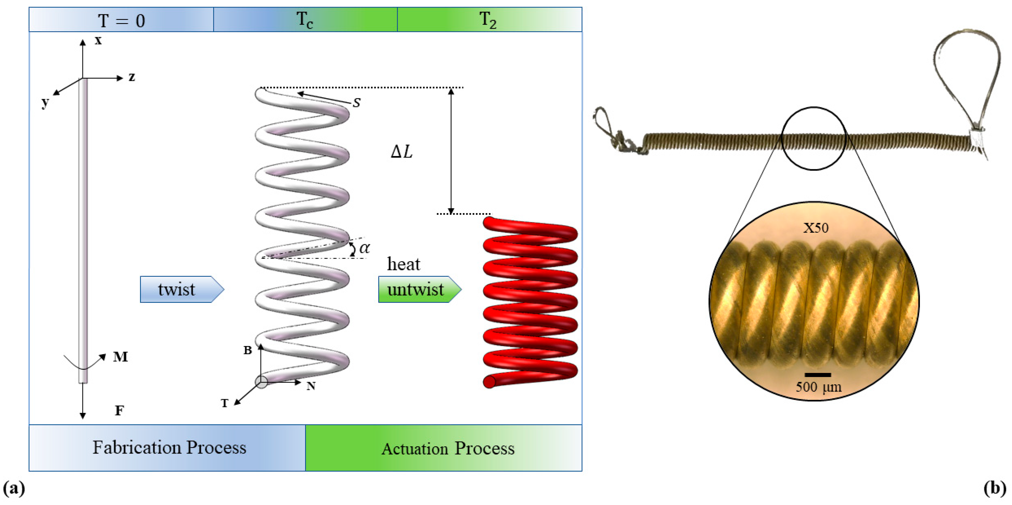
The actuation mechanism of TCP muscles under simulation could be regarded as following steps: (a) during fabrication process, twist is inserted into nylon fibers, then wrap highly twisted fibers around a mandrel to make them coiled, which enables them to amplify tensile stroke; (b) during actuation process, TCP muscles will untwist when subjected to heat because of the positive axial and negative radial thermal expansion coefficient, resulting in a torque that decreases inter-coil separation. The torque will transfer into ‘recovery force’ when two ends of the TCP muscles are fixed to prevent rotating while the twist number inserted in fabrication process turning into length change of TCP muscles, generating actuation stroke and; (c) during recovery process, TCP muscles will twist again and return to unactuated state when the temperature drops.
Therefore, it is concluded that the actuation performance is highly related to how TCP muscles are made. Through single-helix approximation method, it is proved that torsional stroke depends on twist number inserted into the fiber and is independent of fiber diameter [26]. While other studies report that the performance of TCP muscles can also be affected by other factors such as annealing stress, arrangement of fibers, turns per a length, weight per a fiber, and temperature of heat treatment [27,28,29,30]. The influence of twisting speed and plies number on the performance of TCP was discussed thoroughly [31]. It is found that low coiling speed will introduce variation of actuation performance while the twisting frequency close to the natural frequency of the TCP muscles. The use of spandex was introduced as another approach to improve TCP performance [32]. By adjusting those fabrication parameters, various of actuation strain can be obtained. For example, it is shown that the strain can be improved from 3% to 10% by increasing annealing stress [29]; and optimal coiling load can lead to achieve highest muscle stroke up to 40% [32].
As explained above, actuating characteristics of TCP muscles are mainly determined by few fabrication parameters. However, there is a lack of studies demonstrating the reasons for coils forming of TCP muscles and the quantitative relationship between tensile actuation and fabrication load, which may contribute to the further improvement of TCP performance.
In this study, we adopt the theory of elastic bar and present a model showing the quantitative relationship between tensile actuation and fabrication parameters. As mentioned in [16,17], larger actuation strain of TCP can be achieved by increasing twist number inserted into the fibers. However, overtwisted fibers will form curls or improper coiling before wrapping them around a mandrel. Therefore, we identified the critical load and twist of coils forming as key factors and considered these fabrication parameters when deriving the actuation equations of TCP muscles. Firstly, in Section 2.1, the relationship between maximum twist number and fabrication load is derived based on elastic rod theory. Such a relationship explains how the factors like the fiber elastic modulus, fiber shape, and dimensional size could influence the maximum twist number. Now we have the expression of maximum twist number by using fabrication load as independent variable. Therefore, the quantitative relationship between tensile actuation and maximum twist number can be derived. By doing so, we can propose the function between tensile actuation and fabrication load. Secondly, in Section 2.2 the quantitative relationship between tensile actuation and maximum twist number are proposed based on Frenet frame. Finally, the relationship between tensile actuation and fabrication load is obtained. We validated the model through TCP muscles made of silver-coated Nylon 6 fiber under different fabrication load. Recovery stress and maximum stroke of the samples are measured during heating by using a dynamic mechanical analyzer (DMA). The proposed model was also evaluated in terms of the quantitative prediction of the tensile stroke.
2. Modelling Methods
2.1. Modeling of Elastic Bar Buckling and Kinking
To begin with, the relationship between maximum twist number and fabrication load was derived. The maximum twist number is a critical parameter as it will directly determine the actuation strain of TCP [16,17]. While it is found that the formation of twists highly relies on the range of fabrication load. Too heavy a loading will cause break and too low a loading will lead to snarl.
Polymer fibers like nylon, can be twisted into spirals to form TCP muscles. The process of making TCP muscles is usually done with one end of the precursor fibers fixed in the electric motor chuck to provide twist, while a load is applied to the other end to keep the fibers straight (Figure 1a). This process is equivalent to a slender bar subjected to the action of an axial force P and a twisting couple M. The buckling criterion for a slender bar to predict the onset of cable or yarn kinking was introduced to explore the mechanism of coil forming [33]. The ends of the bar are assumed to be attached to the supports by ideal spherical hinges or universal joints, and are free to rotate in any direction. Besides, the axial compressive forces P, the couples M retain their initial directions during bulking. Then, the differential equations of the deflection curve in each plane will be
where E is Young’s modulus and I is moment of inertia about diameter of bar. M and P are the moment and compressive axial force applied to the bar, respectively. To solve these equations, the following boundary conditions were used.
where la is the length of bar. The values for M and P are at which buckling will occur obtained from solutions of Equations (1) and (2) will be given by
Since, for TCP fabrication, tensile force F (instead of compressive forces P) is applied as shown in Figure 1, then Equation (4) becomes
where F = −P. For a slender bar, the bar is long enough that we can assume that
Then Equation (5) becomes
Hence the tensile force F can be expressed as:
During fabrication of TCP muscles, the twisting couple M increases with the twist inserted. Then the twisting couple M will be
where k = torsional stiffness of the bar and θ = rotation angle. It is noticed that k = GJ/I, θ = 2πTc, Tc = twist number inserted, G = shear modulus, and J = Polar moment of inertia, defined as πd4/32 for a cylindrical bar and d = diameter of bar. Now, from Equations (7) and (8), the critical twist number when coiling occurs is turning to
where μ = 0.45 is Poisson’s ratio, E is Young’s modulus, d is the diameter of bar, and F is the applied tensile force. For a slender bar, the twisting couple will accelerate the kinking of the bar. However, an axial tensile force applied to the bar tends to reduce any initial eccentricity caused by the twisting couple, preventing the formation of kinking. The tensile force tends to keep the bar straight while the twisting couple tend to make it kinked. Therefore, when the tension F increases, larger twisting couple is needed to curl the bar into a helical-shape, which requires larger twist number.
2.2. Derivation of TCP Muscles Actuation Mechanism
We now have the expression of Tc by using fabrication load F as independent variable. Then the quantitative relationship between tensile actuation and maximum twist number can be derived. By doing so, we can propose the function between tensile actuation and fabrication load.
The actuation behavior of TCP muscles can be developed by using Love’s theory [16,34]. Hence the tensile stroke of TCP can be calculated from the change of fiber twist as
where L represents the unloaded coil length, N is the number of coil turns, ΔT is the change of twist number, and lc is the fiber length in the coil. While Seyed et al. proposed that the change of fiber twist [35]
where Δτ is the change of torsion. The change of twist can be expressed as (details is shown in Appendix A)
The change of coil length can also be represented as [36]
where la is the fiber length before twisting and d is the fiber diameter. During heating, the fibers’ deformation is minimal and Δla/la ≅ 0. From the definition of “coefficient of thermal expansion”, we can get Δd/d = αtΔT′. Thus, Equation (13) becomes
where αt is the coefficient of thermal expansion and ΔT′ is the change of temperature. Combine Equations (9) and (14), the stoke of TCP muscles with different fabrication load and diameter are given as
where L represents the unloaded coil length, μ is Poisson’s ratio, lc is the fiber length in the coil, E is Young’s modulus, d is the fiber diameter, N is the number of coil turns, F is the applied tensile force, αt is the coefficient of thermal expansion, and ΔT’ is the change of temperature. The Equation (15) suggests that the tensile stroke depends on the fabrication load F and temperature when the material and fiber dimensions are determined. This equation can be used to predict the stroke of a TCP muscles as a function of temperature and fabrication load.
So far, we have a clear mathematical description of actuation strain as a function of fabrication load and temperature.
3. Experiments
In order to validate the effectiveness of the proposed model, experiments were conducted through a prototype of the experimental.
Conductive silver coated Nylon 6 fiber (product number: #40024104600, Shieldex®, diameter: 0.6 mm, lineal resistance: 50 Ω m−1, mass: 0.37 g m−1) was used to fabricate TCP muscle. The thermo-mechanical tests of samples were conducted by DMA Q800 (TA Instruments, New Castle, DE, USA). The thermal distribution of TCP muscles during heating was captured by a thermal imaging Camera T630SC (FLIR® Systems, Inc., Santa Barbara, CA, USA). Microscope image was taken by digital microscope VH-S30 (KEYENCE, Osaka, Japan).
This paper concentrated on homochiral muscles whose chirality of fiber twist matches the coil’s chirality [16]. For homochiral muscles, the direction of helical structure is the same to the fiber twist under the same rule (such as right-hand screw rule). These muscles tend to contract during heating. Silver coated Nylon 6 fibers were twisted before coiling, then wrapped around a mandrel of 1.38 mm diameter. The bottom end of Nylon fiber was loaded with a known weight which was free to move vertically, and rotation was prevented. The other end was twisted by an electrical DC motor. After that, the resulting samples were annealed at 140 °C for 90 min, then cooled to room temperature. Finally, the TCP muscles were obtained.
3.1. Thermo-Mechanical Properties Test of Silver Coated Nylon 6
The thermo-mechanical tests of samples were conducted by DMA Q800 (TA Instruments, New Castle, DE, USA) and carried out in tension mode at a frequency of 1 Hz. The temperature varied from room temperature up to 180 °C with a rate of 3 °C/min, while the length of fibers between clamps was 15 mm. We carried out such experiment to identify elastic modulus under various temperature of commercial purchased silver coated Nylon 6 fibers.
3.2. Strain of TCP Muscles under Different Fabrication Load
In this test, the fiber length is 500 mm and the TCP muscles had a non-loaded length of 42 mm. Samples were heated by applying electric current of 0.2 A. Strain of TCP muscles with different fabrication load was captured by a high-speed camera under different test stress. The upper end of TCP muscles was fixed, while the bottom end was attached to a weight.
3.3. Isometric Recovery Stress of TCP Muscles
TCP muscles were tested in DMA Q800 at constant strain of 30%, heating from room temperature up to 130 °C with a rate of 3 °C/min. TCP muscles tend to contract when heated, which bring about the change of recovery stress.
3.4. Recovery Strain of TCP Muscles During Heating
Recovery strain of TCP muscles change with temperature. TCP muscles were also tested in DMA Q800 at constant force of 0.8 N, heating from room temperature up to 140 °C with a rate of 3 °C/min. The experimental data were compared to theoretical model deduced from Equation (15). The relationship between temperature and actuation strain (shown in Equation (15)) can be validated through these experiments.
4. Results and Discussion
4.1. Twist Number, Maximum Actuation Stroke, and Fabrication Load
The critical twist number of elastic fibers is influenced by the fabrication load during TCP fabrication. The fabrication process can be explained by considering a slender bar subjected to the action of an axial force P and a twisting couple M. With the increase of twist number, the twisting couple M will become bigger leading to the buckling of the slender bar. If the axial force is a compression force, the buckling process could be finished by producing higher and higher bending moment through increasing eccentricity when an initial eccentricity is generated by the torque. However, if the axial force is a tensile force, it will reduce any initial eccentricity caused by the torque. Therefore, larger torque or larger twist number is needed to curl the cable into a helical-shape with a tensile fabrication load.
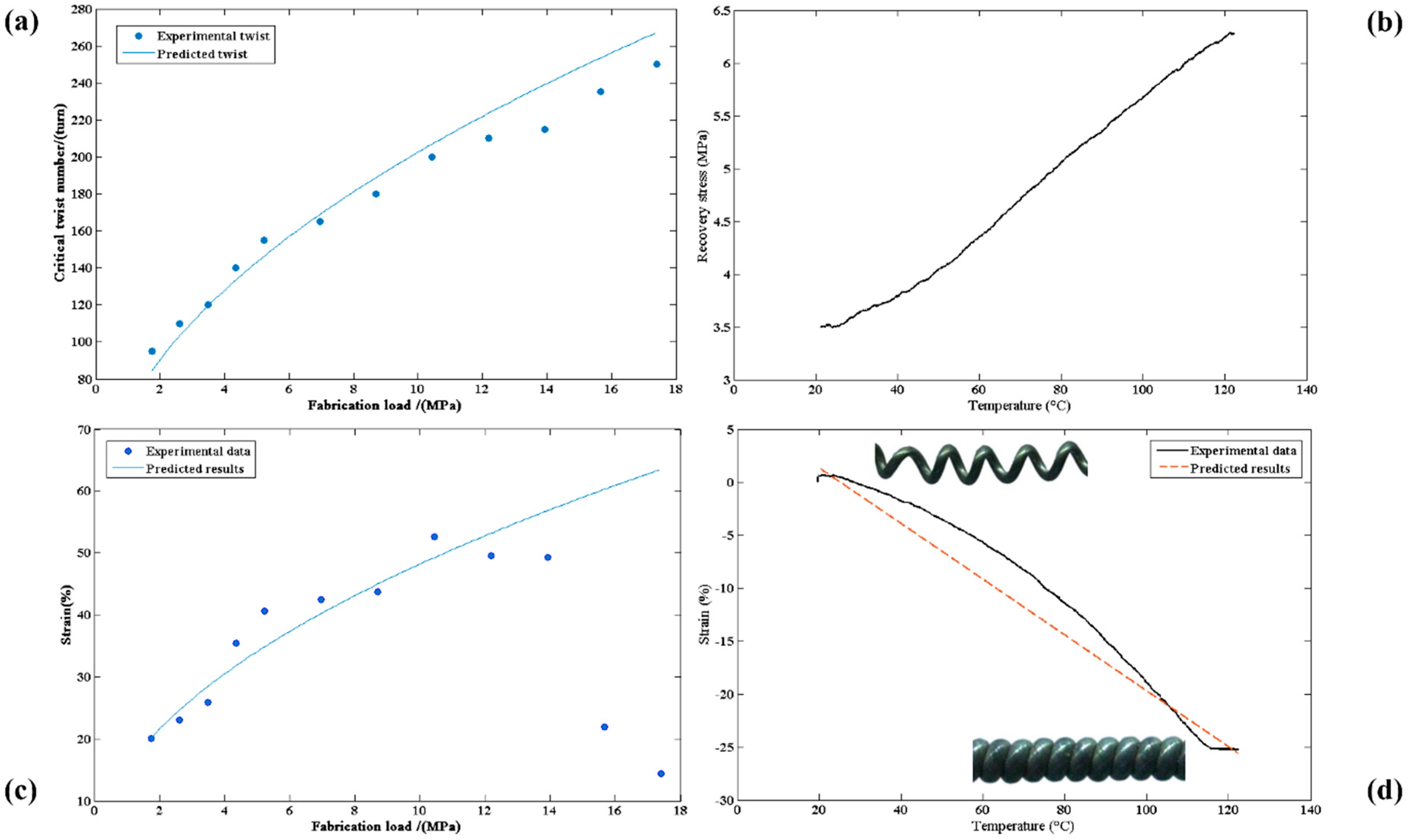
Larger fabrication load requires bigger critical twist number as shown in Equation (9), which means more inserted twists for a given fiber. According to Figure 2a, the fabrication load is adjustable for the same fiber. However, for a Nylon 6 fiber used in experiment, if the applied fabrication load is less than 1.74 MPa, the fiber will snarl; if the applied weight is larger than 17.4 MPa, the fiber will break.
The Equation (15) suggests that the maximum stroke of TCP is also influenced by the fabrication load. This can be illustrated with Figure 2a. The initial twist number is zero. After TCP fabrication, the fiber change from straight to helical structure while the twist number change from zero to critical twist number Tc. During actuation process, TCP muscles will untwist when heated with twist number turning into length change of TCP muscles [16], which means that maximum stroke of TCP muscles will increase with critical twist number Tc, thus increase with fabrication load. According to Figure 2c, the theoretical predictions (shown in Equation (15)) are in agreement with experimental results. However, when applying large fabrication load the results will diverge, which may because of the lack of enough recovery force. For a Nylon 6 fiber of 0.6 mm diameter, it can reach its maximum stroke of 52.6% with 10.44 MPa fabrication load as showed in Figure 2c.
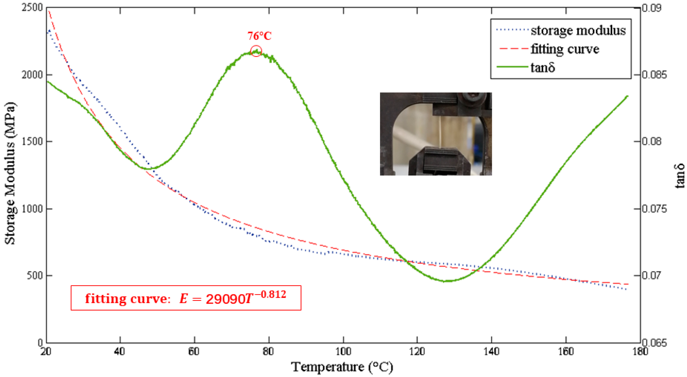
The tensile stroke can be considered as a function of temperature when the fabrication parameters, material, and fiber dimensions are determined (Equation (15) and Figure 2d). Overall, the theoretical predictions are in agreement with experimental results. However, the relationship between temperature and TCP strain is not strictly linear in experiments. This can be explained by Figure 3 and Figure 2b. At the beginning, the temperature is relatively low, the Young’s modulus declines with temperature rapidly, decreasing the elastic recovery stress. When the temperature is above glass transition temperature (76 °C in this paper), the trend become more flat, while the thermal recovery stress is still growing, which increases the whole recovery stress and accelerates the contraction procedure. TCP muscles keep contracting until the adjacent coils come into contact at about 120 °C.
4.2. Actuation Strain and Working Load
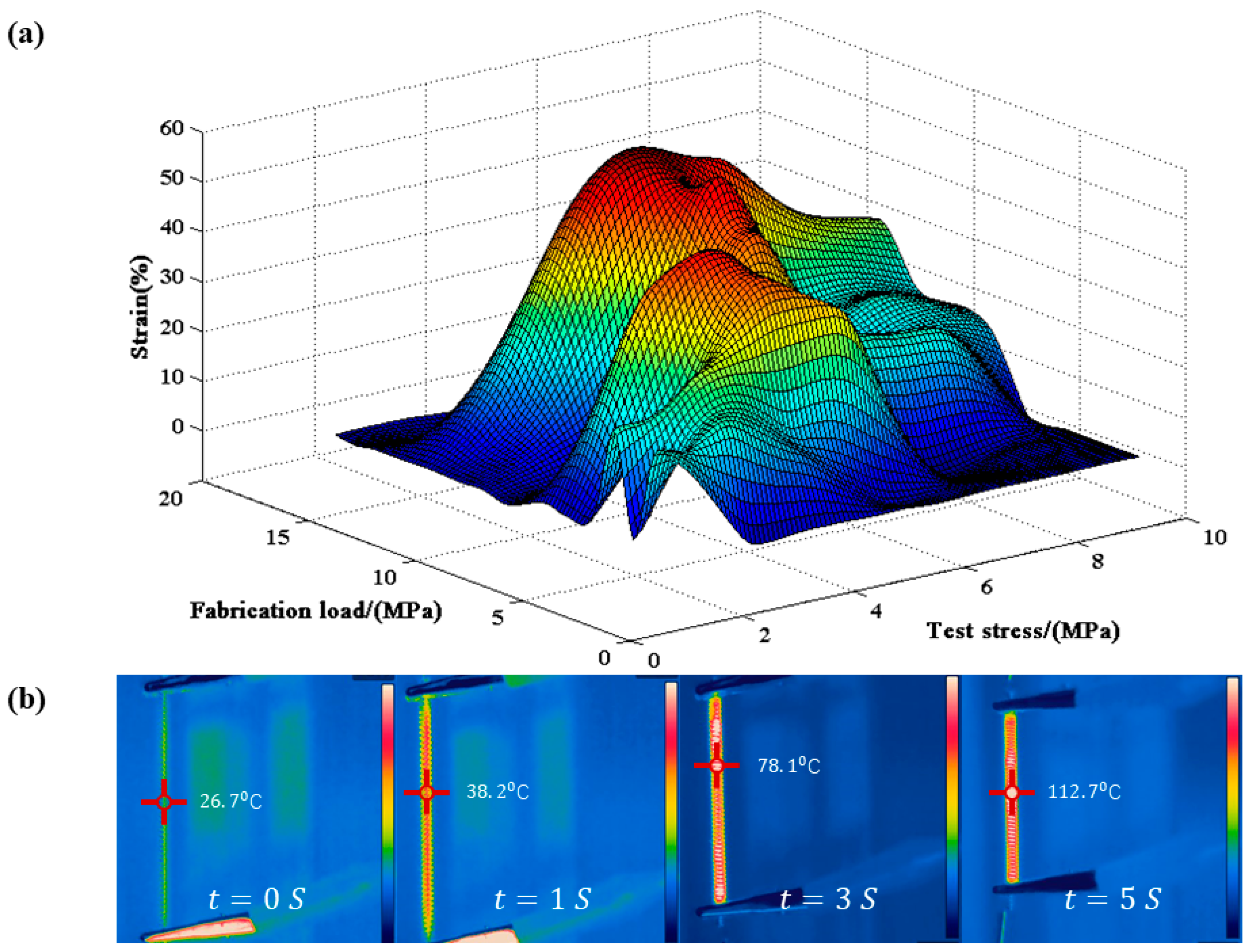
The actuation strain of TCP muscles with different fabrication load versus various stress were shown in Figure 4a. All the TCP muscles show an optimal test stress for maximum strain. For each TCP muscles, when external load is zero, there will be no actuation strain because of inter-coil contact. When there is external stress, TCP muscles will elongate like a spring. Such elongation provides room for shrinking during heating, thus, it determines actuation strain until maximum strain is reached. Further elongation will not increase actuation strain. Moreover, because of the limited recovery stress, TCP muscles will only contract when reaching a higher temperature if excessive test stress is applied. Thus, it will decrease the actuation strain of TCP muscles. For example, the TCP muscle with 10.44 MPa fabrication load shows highest maximum strain of 52.6% under 5.6 MPa. As the fabrication load increases, the optimal test stress tends to increase, which means the promotion of TCP muscle tensile capacity. The muscle with 17.4 MPa fabrication load shows maximum load capacity of 9.8 MPa.
At actuation stage, the whole recovery force is larger than the working load, resulting in the contraction of TCP muscles. The working load will be equivalent to the whole recovery force when the working load reaches the maximum value and the contraction is no longer present. The whole recovery force of TCP muscles FR can be considered as having three separate contrasting components using a traditional mass-damper-spring model as shown below [37].
where Fe = ΔLk is the elastic recovery force, Ft is the thermal recovery force, and Fb is the damping force.
The damping force Fb can be represented as:
where b is the damping coefficient and the method to acquire the value can be obtained in reference [37]. For a helical structure, the stiffness k can be expressed as:
where E can be expressed as E = aTb from experiment result showed in Figure 3 by fitting the curve. Substituting the k from Equation (18) into the Equation (16) we have
where Ft can be expressed as Ft = 0.015(T-25) from experiment result showed in Figure 2b by fitting the curve.
4.3. Maximum Work Capacity
The stroke of TCP muscles is influenced by the external loading conditions as shown in Figure 4. The model describing the relationship between actuation strain and testing load is complicated. Thus, it is a popular way to predict the stroke of TCP muscles under different loading conditions by experiments [38].
As explained above, we are lacking expression between actuation strain and testing load. However, we can still roughly estimate the maximum specific work of the TCP muscles based on Equation (15). The calculation of maximum specific work can be simplified as the product of maximum working load and maximum stroke. For a helical structure, the maximum tensile force is limited by its shear strength. When applied compressive axial force P, the shear stress τ of a helical structure can be expressed as
where C is spring index which is the ratio of mean coil diameter D2 to the fiber diameter d and P = −F. According to Equation (20), the maximum tensile force F can be expressed as
Combine Equations (15) and (21), the work of TCP muscles is derived as
For a helical structure, the maximum tensile force is limited by its shear strength. According to Equation (21), the maximum tensile force can be obtained when shear stress τ = τc. Where τc = 60.7 MPa, the shear strength of Nylon 6.
In our experiment, for given 0.6 mm diameter Nylon fiber, it is calculated as 10.15 MPa, which is quite close to experiment data of 10.44 MPa, as shown in Figure 2c. The value of optimal fabrication load and maximum test load can be considered as equivalent to the maximum tensile force. Furthermore, as shown in Figure 4a, the maximum test load that could sustained is about 9.8 MPa. Therefore, the maximum specific work of TCP muscles was also limited by shear strength. TCP muscles with better performance require materials of larger shear strength.
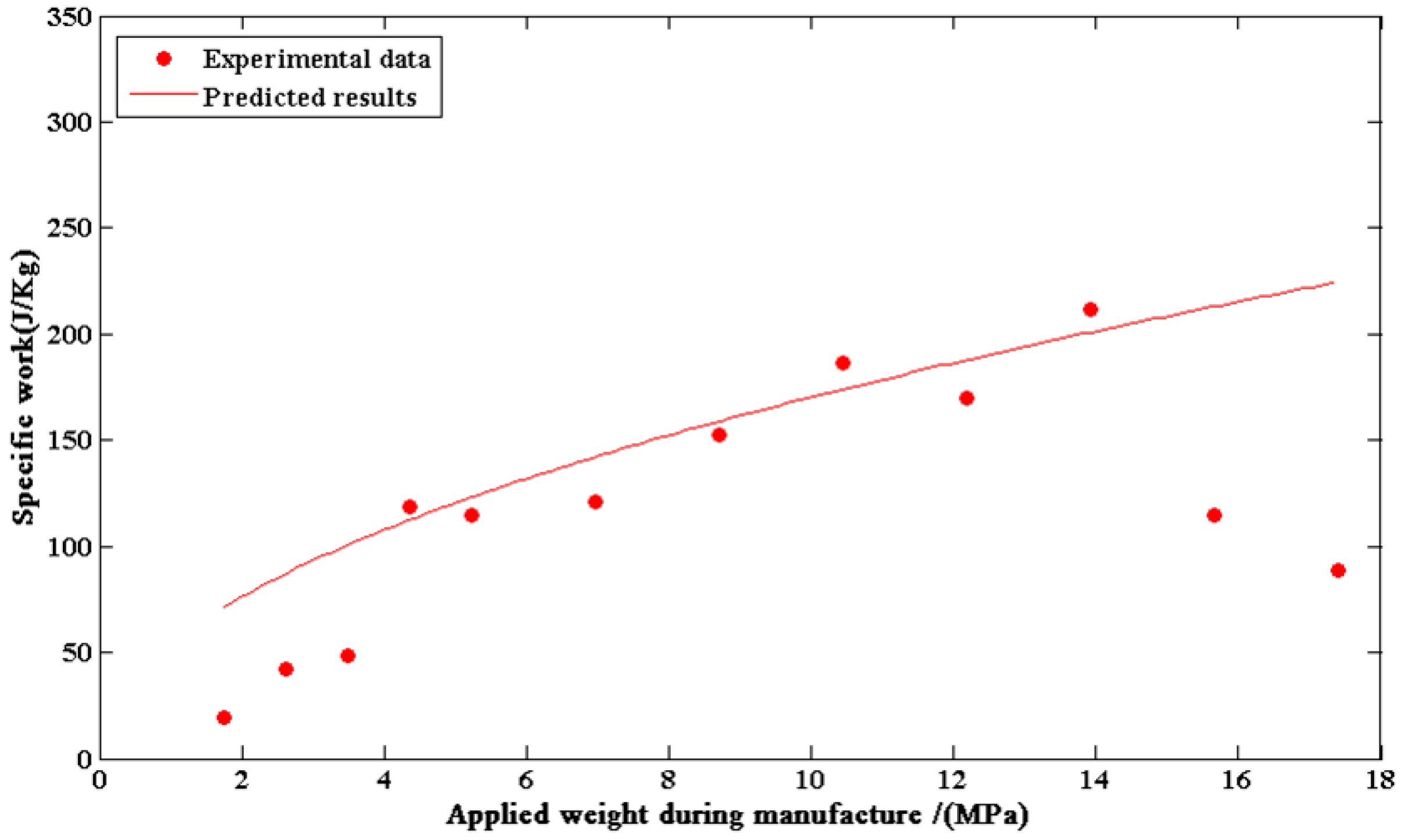
The maximum specific work during actuation was 211.89 J/kg for the 13.92 MPa fabrication load TCP muscle as shown in Figure 5, which is 5 times that for human muscle and 35 times that for fish muscle. It is relatively smaller than data reported in references [16,39]. The work efficiency is also carefully checked with value of 0.4%. The divergency between experimental data and predicted results at low or high fabrication samples may also blame to the lack of enough recovery force. In the experiments, the whole recovery force is relatively small compared with working load when the fabrication load is at low or high level, preventing the further contraction of TCP muscles, which affects the maximum specific work.
5. Conclusions
In this paper, an elastic-rod-theory-based model was established and validated for explaining the quantitative relationship between tensile actuation and fabrication load. For modeling building, firstly, the relationship between maximum twist number and fabrication load is derived based on elastic rod theory. The maximum twist number that could insert into the TCP muscles which directly determine the stroke of TCP depends on the fiber elastic modulus, dimensional size, and fabrication load applied during fabrication. Such a relationship explains how these factors could influence the maximum twist number. Next, the quantitative relationship between tensile actuation and maximum twist number are proposed based on Frenet frame. Finally, the relationship between tensile actuation and fabrication load can be obtained. The model can also be used to predict the tensile stroke as a function of temperature. For model validation and parametric study, TCP muscles made of silver-coated Nylon 6 fiber were fabricated under different fabrication load. Recovery stress, recovery strain, and maximum stroke of the samples with different fabrication load were measured during heating by using a dynamic mechanical analyzer. Finally, we evaluated the model in terms of the quantitative prediction of the tensile stroke. The theoretical predictions were in agreement with experimental results. The results show that the TCP muscles of 10.44 MPa fabrication load were capable of demonstrating maximum stroke of 52.6% with a specific work of 186.49 J/kg.
For real application, the model provides a guideline for choosing desired fiber materials, fiber shape, or dimensional size. Further works could be on improving of efficiency and building control strategy of TCP muscles. Therefore, those compliant, safe, non-noised, and cheap muscles can be used in rehabilitation robots, intelligent equipment, aquatic robots design, etc.
Author Contributions
W.Z. initiated and supervised the development of the differential soft actuator, C.W. build the model, fabricated the actuator, constructed the experimental environment, and performed the experiment. Both authors wrote this paper. All authors have read and agreed to the published version of the manuscript.
Funding
This research was funded by the financial support from National Natural Science Foundation of China (NSCF grant No.51705313) and Natural Science Foundation of Shanghai (17ZR1414600).
Conflicts of Interest
The authors declare no conflict of interest.
Appendix A
Seyed et al. proposed that the change of fiber twist [35]
where Δτ is the change of torsion.
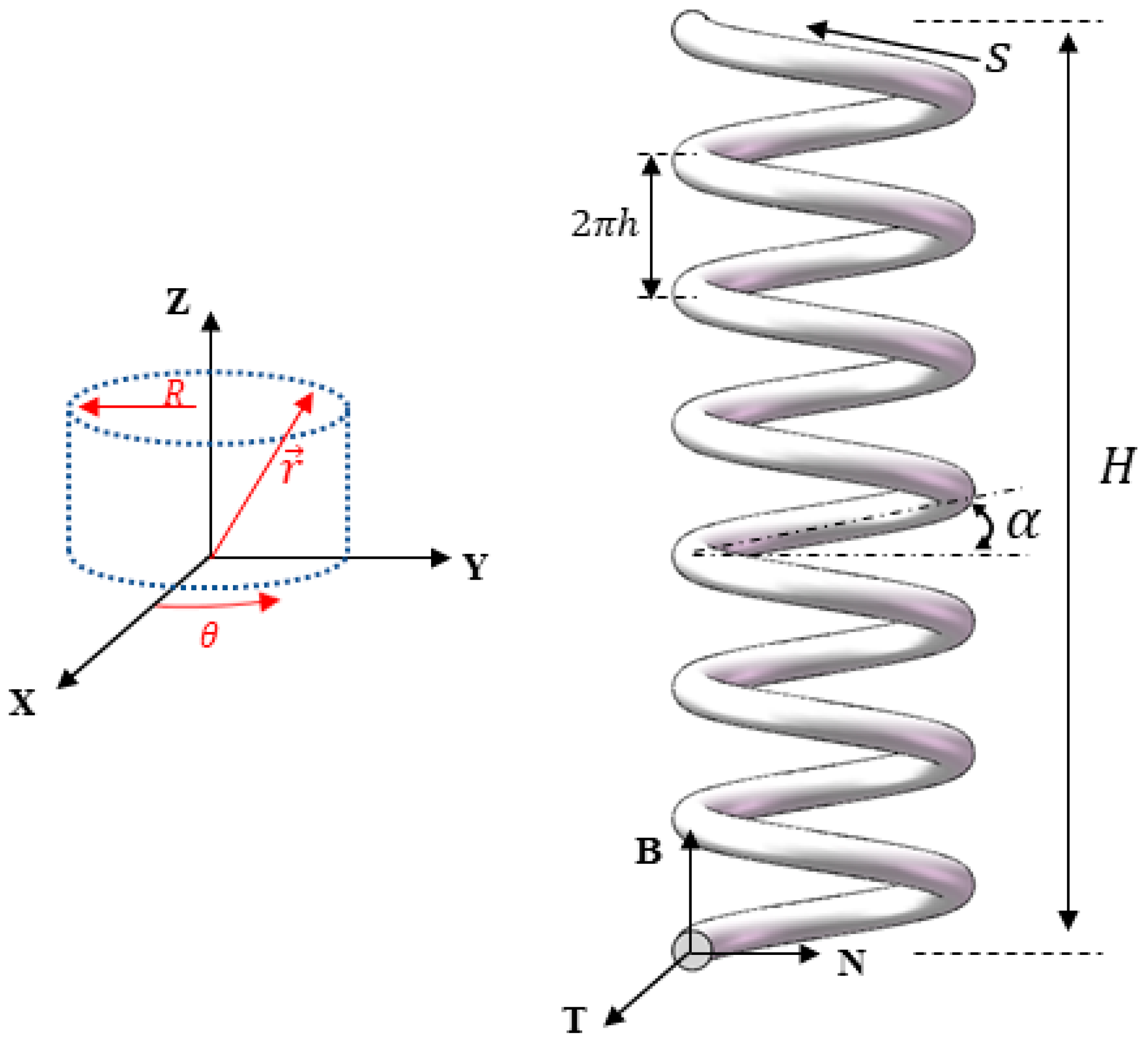
The relationship between fiber twist and TCP muscle stroke can be derived by Frenet–Serret frame. The Frenet–Serret frame consists of the tangent T, normal N, and binormal B, collectively, forming an orthonormal basis of 3-space (as shown in Figure A1). The frame means that this coordinate system is constantly rotating as an observer moves along the curve. While Frenet–Serret (parameters required are shown in Figure A1) equations can be expressed as
where , , and are tangential, normal, and binormal unit, respectively, and κ, τ are the curvature and torsion. They are defined as
Figure A1.
Illustration of Frenet–Serret frame

In Cartesian coordinate, the position vector can be expressed as
where h = H/2nπ is the helix pitch per radian. Then ds will be
Now, Equation (A3) becomes
where α is coil bias angle. Then, consider that sin α = R/ and cos α = h/, the change of twist can be obtained by using Equations (A1), (A4), and (A7) as
References
- Trivedi, D.; Rahn, C.D.; Kier, W.M.; Walker, I.D. Soft robotics: Biological inspiration, state of the art, and future research. Appl. Bionics Biomech. 2008, 5, 99–117. [Google Scholar] [CrossRef]
- Rus, D.; Tolley, M.T. Design, fabrication and control of soft robots. Nature 2015, 521, 467–475. [Google Scholar] [CrossRef] [Green Version]
- Pyo, D.; Lim, J.M.; Mun, S.; Yun, S. Silver-Nanowires Coated Pitch-Tuned Coiled Polymer Actuator for Large Contractile Strain under Light-Loading. Int. J. Precis. Eng. Manuf. 2018, 19, 1895–1900. [Google Scholar] [CrossRef]
- Shigemune, H.; Sugano, S.; Nishitani, J.; Yamauchi, M.; Hosoya, N.; Hashimoto, S.; Maeda, S. Dielectric Elastomer Actuators with Carbon Nanotube Electrodes Painted with a Soft Brush. Actuators 2018, 7, 51. [Google Scholar] [CrossRef] [Green Version]
- Verma, M.; Ainla, A.; Yang, D.; Harburg, D.; Whitesides, G.M. A Soft Tube-Climbing Robot. Soft Robot. 2017, 5, 133–137. [Google Scholar] [CrossRef]
- Glick, P.; Suresh, S.A.; Ruffatto, D.; Cutkosky, M.R.; Tolley, M.T.; Parness, A. A Soft Robotic Gripper with Gecko-Inspired Adhesive. IEEE Robot. Autom. Lett. 2018, 3, 903–910. [Google Scholar] [CrossRef]
- Ohta, P.; Valle, L.; King, J.; Low, K.; Yi, J.; Atkeson, C.G.; Park, Y.-L. Design of a Lightweight Soft Robotic Arm Using Pneumatic Artificial Muscles and Inflatable Sleeves. Soft Robot. 2018, 5, 204–215. [Google Scholar] [CrossRef] [Green Version]
- Hošovský, A.; Pitel, J.; Zidek, K.; Tóthová, M.; Sarosi, J.; Cveticanin, L. Dynamic characterization and simulation of two-link soft robot arm with pneumatic muscles. Mech. Mach. Theory 2016, 103, 98–116. [Google Scholar] [CrossRef]
- Cveticanin, L.; Žukovič, M.; Biró, I.; Sarosi, J. Mathematical investigation of the stability condition and steady state position of a pneumatic artificial muscle—Mass system. Mech. Mach. Theory 2018, 125, 196–206. [Google Scholar] [CrossRef]
- Li, S.; Vogt, D.M.; Rus, D.; Wood, R.J. Fluid-driven origami-inspired artificial muscles. Proc. Natl. Acad. Sci. USA 2017, 114, 13132–13137. [Google Scholar] [CrossRef] [Green Version]
- Li, W.-B.; Zhang, W.-M.; Zou, H.-X.; Peng, Z.-K.; Meng, G. A Fast Rolling Soft Robot Driven by Dielectric Elastomer. IEEE-ASME Trans. Mechatron. 2018, 23, 1630–1640. [Google Scholar] [CrossRef]
- Bozlar, M.; Punckt, C.; Korkut, S.; Zhu, J.; Foo, C.C.; Suo, Z.; Aksay, I.A. Dielectric elastomer actuators with elastomeric electrodes. Appl. Phys. Lett. 2012, 101, 91907. [Google Scholar] [CrossRef] [Green Version]
- Koh, S.J.A.; Li, T.; Zhou, J.; Zhao, X.; Hong, W.; Zhu, J.; Suo, Z. Mechanisms of large actuation strain in dielectric elastomers. J. Polym. Sci. Part B Polym. Phys. 2011, 49, 504–515. [Google Scholar] [CrossRef]
- Duduta, M.; Hajiesmaili, E.; Zhao, H.; Wood, R.J.; Clarke, D.R. Realizing the potential of dielectric elastomer artificial muscles. Proc. Natl. Acad. Sci. USA 2019, 116, 2476–2481. [Google Scholar] [CrossRef] [Green Version]
- Li, P.; Jin, Z.; Peng, L.; Zhao, F.; Xiao, D.; Jin, Y.; Yu, G. Stretchable All-Gel-State Fiber-Shaped Supercapacitors Enabled by Macromolecularly Interconnected 3D Graphene/Nanostructured Conductive Polymer Hydrogels. Adv. Mater. 2018, 30, 1800124. [Google Scholar] [CrossRef]
- Haines, C.S.; Lima, M.D.; Li, N.; Spinks, G.M.; Foroughi, J.; Madden, J.D.W.; Kim, S.H.; Fang, S.; De Andrade, M.J.; Göktepe, F.; et al. Artificial Muscles from Fishing Line and Sewing Thread. Science 2014, 343, 868–872. [Google Scholar] [CrossRef]
- Haines, C.S.; Li, N.; Spinks, G.M.; Aliev, A.E.; Di, J.; Baughman, R.H. New twist on artificial muscles. Proc. Natl. Acad. Sci. USA 2016, 113, 11709–11716. [Google Scholar] [CrossRef] [Green Version]
- Tang, X.; Li, K.; Liu, Y.; Zhou, D.; Zhao, J. A general soft robot module driven by twisted and coiled actuators. Smart Mater. Struct. 2019, 28, 035019. [Google Scholar] [CrossRef]
- Cho, K.H.; Jung, H.S.; Yang, S.Y.; Kim, Y.; Rodrigue, H.; Moon, H.; Koo, J.C.; Choi, H.R.; Hugo, R. Sliding Filament Joint Mechanism: Biomimetic Artificial Joint Mechanism for Artificial Skeletal Muscles. J. Mech. Robot. 2019, 11, 021004. [Google Scholar] [CrossRef]
- Wu, L.; Chauhan, I.; Tadesse, Y. A Novel Soft Actuator for the Musculoskeletal System. Adv. Mater. Technol. 2018, 3, 1700359. [Google Scholar] [CrossRef]
- Bahrami, S.; Dumond, P. Testing of Coiled Nylon Actuators for Use in Spastic Hand Exoskeletons. In Proceedings of the 40th Annual International Conference of the IEEE Engineering in Medicine and Biology Society (EMBC), Honolulu, HI, USA, 17–21 July 2018; pp. 1853–1856. [Google Scholar]
- Wu, L.; De Andrade, M.J.; Saharan, L.K.; Rome, R.S.; Baughman, R.H.; Tadesse, Y. Compact and low-cost humanoid hand powered by nylon artificial muscles. Bioinspir. Biomim. 2017, 12, 026004. [Google Scholar] [CrossRef]
- Li, Y.; Wu, Z. Stabilization of floating offshore wind turbines by artificial muscle based active mooring line force control. In Proceedings of the 2016 American Control Conference (ACC), Boston, MA, USA, 6–8 July 2016; pp. 2277–2282. [Google Scholar]
- Kim, S.H.; Lima, M.D.; Kozlov, M.; Haines, C.S.; Spinks, G.M.; Aziz, S.; Choi, C.; Sim, H.J.; Wang, X.; Lu, H.; et al. Harvesting temperature fluctuations as electrical energy using torsional and tensile polymer muscles. Energy Environ. Sci. 2015, 8, 3336–3344. [Google Scholar] [CrossRef] [Green Version]
- Almubarak, Y.; Tadesse, Y. Twisted and coiled polymer (TCP) muscles embedded in silicone elastomer for use in soft robot. Int. J. Intell. Robot. Appl. 2017, 1, 352–368. [Google Scholar] [CrossRef]
- Aziz, S.; Naficy, S.; Foroughi, J.; Brown, H.R.; Spinks, G.M. Controlled and scalable torsional actuation of twisted nylon 6 fiber. J. Polym. Sci. Part B Polym. Phys. 2016, 54, 1278–1286. [Google Scholar] [CrossRef] [Green Version]
- Moretti, G.; Cherubini, A.; Vertechy, R.; Fontana, M. Experimental characterization of a new class of polymeric-wire coiled transducers. In Behavior and Mechanics of Multifunctional Materials and Composites 2015; Goulbourne, N.C., Ed.; SPIE: Bellingham, WA, USA, 2015; Volume 9432. [Google Scholar]
- Semochkin, A.N. A device for producing artificial muscles from nylon fishing line with a heater wire. In Proceedings of the 2016 IEEE International Symposium on Assembly and Manufacturing (ISAM), Fort Worth, TX, USA, 21–22 August 2016; pp. 26–30. [Google Scholar]
- Li, T.; Wang, Y.; Liu, K.; Liu, H.-B.; Zhang, J.; Sheng, X.; Guo, D. Thermal actuation performance modification of coiled artificial muscle by controlling annealing stress. J. Polym. Sci. Part B Polym. Phys. 2017, 56, 383–390. [Google Scholar] [CrossRef]
- Cho, K.H.; Song, M.-G.; Jung, H.; Yang, S.Y.; Moon, H.; Koo, J.C.; Nam, J.-D.; Choi, H.R. Fabrication and modeling of temperature-controllable artificial muscle actuator. In Proceedings of the 6th IEEE International Conference on Biomedical Robotics and Biomechatronics (BioRob), Singapore, 26–29 June 2016; pp. 94–98. [Google Scholar]
- Saharan, L.; Tadesse, Y. Fabrication Parameters and Performance Relationship of Twisted and Coiled Polymer Muscles. In Proceedings of the ASME 2016 International Mechanical Engineering Congress and Exposition, Phoenix, AZ, USA, 11–17 November 2016; Volume 14. [Google Scholar]
- Kim, K.; Cho, K.H.; Jung, H.S.; Yang, S.Y.; Kim, Y.; Park, J.H.; Jang, H.; Nam, J.-D.; Koo, J.C.; Moon, H.; et al. Double Helix Twisted and Coiled Soft Actuator from Spandex and Nylon. Adv. Eng. Mater. 2018, 20, 6. [Google Scholar] [CrossRef]
- Timoshenko, S.P.; Gere, J.M. Theory of Elastic Stability; McGraw-Hill: London, UK, 1961. [Google Scholar]
- Love, A.E.H. A Treatise on the Mathematical Theory of Elasticity; Cambridge University Press: Cambridge, UK, 2013. [Google Scholar]
- Mirvakili, S.M.; Ravandi, A.R.; Hunter, I.W.; Haines, C.S.; Li, N.; Foroughi, J.; Naficy, S.; Spinks, G.M.; Baughman, R.H.; Madden, J.D.W. Simple and strong: Twisted silver painted nylon artificial muscle actuated by Joule heating. In Electroactive Polymer Actuators and Devices (EAPAD) 2014; SPIE: Bellingham, WA, USA, 2014; Volume 9056. [Google Scholar]
- Hiraoka, M.; Nakamura, K.; Arase, H.; Asai, K.; Kaneko, Y.; John, S.W.; Tagashira, K.; Omote, A. Power-efficient low-temperature woven coiled fibre actuator for wearable applications. Sci. Rep. 2016, 6, 36358. [Google Scholar] [CrossRef]
- Yip, M.C.; Niemeyer, G. On the Control and Properties of Supercoiled Polymer Artificial Muscles. IEEE Trans. Robot. 2017, 33, 689–699. [Google Scholar] [CrossRef]
- Spinks, G.M.; Bakarich, S.E.; Aziz, S.; Salahuddin, B.; Xin, H. Using force-displacement relations to obtain actuation parameters from artificial muscles. Sens. Actuators A Phys. 2019, 290, 90–96. [Google Scholar] [CrossRef]
- Rome, L.C.; Swank, D. The influence of temperature on power output of scup red muscle during cyclical length changes. J. Exp. Boil. 1992, 171, 261–281. [Google Scholar]
Figure 1.
Schematic illustration of the coil process and thermally induced tensile actuation of twisted and coiled polymer (TCP) muscle: (a) schematics of the TCP fabrication and actuation process. The fabrication process could be understood by considering a slender bar subjected to the action of a tensile force F and a twisting couple M. In the actuation process, TCP muscles will untwist when heated with twist number turning into length change of TCP muscles. (b) microscope images of TCP muscle.

Figure 2.
Performance of the TCP muscles (a) critical twist number of Nylon 6 fiber from different fabrication load; (b) recovery stress curve of a TCP muscle with 3.48 MPa fabrication load at constant strain of 30%; (c) maximum strain of TCP muscles from different fabrication load; and (d) recovery strain curve of a TCP muscle with 3.48 MPa fabrication load at constant tensile force of 0.8 N.

Figure 3.
Storage modulus (dot line), fitting curve (dash line), and tanδ (solid line). tanδ is the ratio of loss modulus (not shown in this figure) to storage modulus whose first maximum point can be used to locate the glass transition temperature.
Figure 3.
Storage modulus (dot line), fitting curve (dash line), and tanδ (solid line). tanδ is the ratio of loss modulus (not shown in this figure) to storage modulus whose first maximum point can be used to locate the glass transition temperature.

Figure 4.
Strain test results of the TCP muscles (a) strain of TCP samples from various fabrication load and test stress and (b) the temperature distribution along the TCP muscle’s surface. The cursor indicates temperature at that spot.
Figure 4.
Strain test results of the TCP muscles (a) strain of TCP samples from various fabrication load and test stress and (b) the temperature distribution along the TCP muscle’s surface. The cursor indicates temperature at that spot.

Figure 5.
Maximum specific work of the TCP muscles with different fabrication load

© 2020 by the authors. Licensee MDPI, Basel, Switzerland. This article is an open access article distributed under the terms and conditions of the Creative Commons Attribution (CC BY) license (http://creativecommons.org/licenses/by/4.0/).
Share and Cite
MDPI and ACS Style
Wu, C.; Zheng, W. A Modeling of Twisted and Coiled Polymer Artificial Muscles Based on Elastic Rod Theory. Actuators 2020, 9, 25. https://0-doi-org.brum.beds.ac.uk/10.3390/act9020025
AMA Style
Wu C, Zheng W. A Modeling of Twisted and Coiled Polymer Artificial Muscles Based on Elastic Rod Theory. Actuators. 2020; 9(2):25. https://0-doi-org.brum.beds.ac.uk/10.3390/act9020025
Chicago/Turabian StyleWu, Chunbing, and Wen Zheng. 2020. "A Modeling of Twisted and Coiled Polymer Artificial Muscles Based on Elastic Rod Theory" Actuators 9, no. 2: 25. https://0-doi-org.brum.beds.ac.uk/10.3390/act9020025
Note that from the first issue of 2016, this journal uses article numbers instead of page numbers. See further details here.