Styrenic-Rubber Dielectric Elastomer Actuator with Inherent Stiffness Compensation
by
 , , and
Giacomo Moretti
1 ,
,
Luca Sarina
2,
Lorenzo Agostini
1,
Rocco Vertechy
3,
Giovanni Berselli
4 and
Marco Fontana
2,*
1
TeCIP Institute, Scuola Superiore Sant’Anna, 56127 Pisa, Italy
2
Department of Industrial Engineering, University of Trento, 38123 Trento, Italy
3
Department of Industrial Engineering, University of Bologna, 40166 Bologna, Italy
4
Department of Mechanical, Energy, Management and Transportation Engineering, University of Genova, 16145 Genova, Italy
*
Author to whom correspondence should be addressed.
Actuators 2020, 9(2), 44; https://0-doi-org.brum.beds.ac.uk/10.3390/act9020044
Submission received: 28 April 2020
/
Revised: 16 May 2020
/
Accepted: 26 May 2020
/
Published: 5 June 2020
(This article belongs to the Special Issue Dielectric Elastomer Actuators (DEAs))
Abstract
:Up to date, Dielectric Elastomer Actuators (DEA) have been mostly based on either silicone or acrylic elastomers, whereas the potential of DEAs based on inexpensive, wide-spread natural and synthetic rubbers has been scarcely investigated. In this paper, a DEA based on a styrene-based rubber is demonstrated for the first time. Using a Lozenge-Shaped DEA (LS-DEA) layout and following a design procedure previously proposed by the authors, we develop prototypes featuring nearly-zero mechanical stiffness, in spite of the large elastic modulus of styrenic rubber. Stiffness compensation is achieved by simply taking advantage of a biaxial pre-stretching of the rubber DE membrane, with no need for additional stiffness cancellation mechanical elements. In the paper, we present a characterization of the styrene rubber-based LS-DEA in different loading conditions (namely, isopotential, isometric, and isotonic), and we prove that actuation strokes of at least 18% the actuator side length can be achieved, thanks to the proposed stiffness-compensated design.
1. Introduction
Dielectric Elastomers (DEs) are a particular class of smart materials that can provide bi-directional conversion between mechanical energy and direct electricity, enabling the production of intrinsically compliant and integrated actuators, sensors, or generators. In essence, DEs are deformable dielectrics, which can experience deviatoric finite deformations in response to electric fields of adequate intensity. Typical electro-mechanical properties [1,2,3] are large dielectric strength (electric breakdown, 30–300 MV/m), relative dielectric constant in the range 2–10, high volume resistance ( 0.2–1000 ), incompressibility (Poisson’s ratio ), large ultimate stretch ( 200–800%), and low-to-moderate shear modulus (i.e., infinitesimal initial shear modulus 20–500 kPa). In the current state-of-the-art, these smart materials have been successfully employed in a large variety of applications, such as human-like artificial muscles for soft robots (e.g., [4,5,6]), strain and pressure sensors (e.g., [7,8]), and energy harvesters from natural resources (e.g., [9,10]). Currently, the DE governing principle is well known: an incompressible and electrically non-conductive polymeric membrane is coated with compliant electrodes to form a highly deformable capacitor. In actuator mode, the placement of a voltage between the electrodes can produce a film area expansion that can be used to produce useful mechanical work. In generator mode, external forces shrink the elastomeric membrane in area, thus reducing the DE capacitance and increasing the electric potential of charges deposited on the electrodes. In sensor mode, a direct measurement of the variation in the DE electrical resistance and/or capacitance is used to gather information about external forces and/or displacements.
Exemplary well-known DE materials that are available in the from of thin films are: (1) acrylic elastomers such as VHB 4905/4910, (2) silicone elastomers such as Wacker Elastosil, and (3) other natural or synthetic rubbers such as rubber films employed for exercise bands. Acrylic VHB elastomer has been widely used to build DE Actuators (DEAs) due to its low shear modulus (), which allows the electrostatic forces to easily overcome the DE elastic forces and produce large strokes [11,12]. However, this material is prone to large electromechanical losses [3] and offers scarce reliability upon cyclic loading [13]. Silicones and other types of rubber seem a more promising option for efficient and durable real-world devices due to their reduced electromechanical losses and to their better reliability and lifetime. However, they generally present a significantly larger shear modulus () that makes the implementation of actuators more complex. Silicone DEAs capable of actuation strains over 10% have been built using negative-stiffness mechanisms, so as to compensate for the large elastic forces [14,15], while other types of rubbers such as natural rubbers have been only used in DE generators [16,17], but their application in actuators is unexplored to date. Compared to silicone, natural or styrenic rubbers represent a much less expensive alternative with the costs of raw materials of a few euros per kilogram. In addition, with respect to natural rubbers, synthetic styrenic rubbers show minor degradations of dielectric strength after exposition to water, resulting in a potentially better tolerance to long-term exposition to atmospheric humidity [18].
The simplest conceivable DEA can be obtained by first pre-stretching a single DE membrane or a stack of membranes and by coupling segments of their boundaries to the links of a supporting mechanism. Stiffness compensation compliant elements may also be designed so as to modify the DEA force-deflection response, eventually obtaining mono-/bi-directional and constant-force (i.e., zero-stiffness) actuators [12]. Similarly to pneumatic/hydraulic cylinders, DEAs providing a constant thrust are typically desirable as they are easy to control and provide a uniform behavior throughout their workspace. Potential applications can be found in compliant grippers for handling of soft objects [19], tactile devices [20], and material machining/testing where a constant force should be applied to complex surfaces despite wear [21].
The Lozenge-Shaped DEA (LS-DEA) is a special layout that drastically simplifies the overall DEA design. This topology was first studied by Plante and Dubowsky [22,23], who developed an LS-DEA prototype with acrylic DE and provided it with elastic stiffness compensation elements to increase the achievable stroke. Then, Vertechy et al. [24] proposed a mathematical procedure to design an acrylic-based LS-DEA with nearly-zero stiffness free of any external stiffness compensation element.
The possibility of achieving low stiffness without external compensation elements makes the LS-DEA an interesting topology to be used in combination with tougher, but rather stiff DEs (rubber or silicone). In this regard, the present work provides experimental evidence that LS-DEAs with nearly-zero mechanical stiffness can be implemented leveraging the electromechanical properties of styrenic rubber.
The paper is structured as follows. Section 2 describes the LS-DEA layout and introduces an analytical electromechanical model. Section 3 illustrates the design of an LS-DEA made of styrenic rubber that takes advantage of the self-compensation principle. Section 4 presents the implementation of a prototype and the setup predisposed for its experimental characterization campaign, whose results are presented in Section 5. Conclusions and a discussion on the advantages and disadvantages of the proposed DEA are finally provided in Section 6.
2. Layout and Modeling
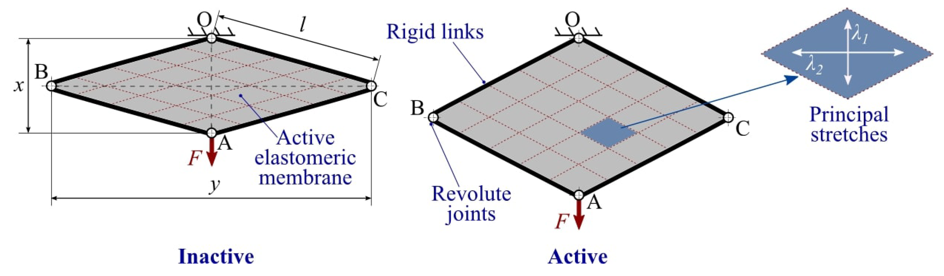
The DEA considered in this work is referred to as a Lozenge-Shaped DEA (LS-DEA) [24]. It consists of a planar active elastomeric membrane, the perimeter of which is connected to the rigid links of a four bar mechanism with identical links. The active membrane consists of a DE layer (or stack of layers) with the shape of a rhombus (namely, a lozenge) coated on both faces by compliant electrodes. The mechanism holding the active membrane has four links with equal lengths connected by revolute joints and is hereafter referred to as a lozenge mechanism.
A schematic of the LS-DEA is shown in Figure 1. One of the joints of the actuator (revolute pair O in the figure) is connected to a fixed frame, whereas the opposite joint (A) serves as the actuator end effector. In operating conditions, the LS-DEA is subject to a force F parallel to diagonal OA. Applying a voltage difference on the device electrodes generates an increase in the LS-DEA capacitance, i.e., an increase in the electrodes’ area, and due to the active membrane incompressibility [25], a reduction in thickness. Such a shape variation results in a linear displacement of the end effector point A in the direction of diagonal OA (namely, a linear actuation).
The system has one kinematic degree-of-freedom; hence, its configuration can be entirely described in terms of the length x of diagonal OA. The length of diagonal BC (perpendicular to OA) can be thus expressed as a function of x as follows:
where l is the length of the lozenge mechanism links.
If the perimeter of the membrane is rigidly attached to the links of the parallelogram mechanism and the membrane is free to expand in the thickness direction, then the elastomer deforms uniformly [23]. Lozenge-shaped membrane elements whose diagonals are parallel to the mechanism diagonals and whose aspect ratio is the same as that of the mechanism maintain a lozenge shape upon deformation (see Figure 1). Directions x and y and the thickness directions are thus principal deformation directions. This holds with good approximation everywhere over the membrane, except for small areas close to the mechanism links (where constraints on the thickness deformation might be present). Building upon this assumption, it is possible to build a simple and computationally-inexpensive model, which is useful for LS-DEA design.
The active membrane is mounted on the mechanism links with a certain degree of pre-stretch along the x and y directions, aimed at preventing loss of mechanical tension in the presence of electrostatic stress. Choosing a reference configuration such that and , we assume that the corresponding stretches in the x and y directions are known, and they are respectively equal to and , hereafter referred to as the pre-stretches. The principal stretches in the x and y directions in a generic configuration read as follows:
while, owing to incompressibility, the stretch in the thickness direction is .
A model for the electro-elastic response of lozenge-shaped DE transducers was proposed in [24] and generalized in [17,26]. The mechanical response of the active membrane is described through a hyperelastic model [25].
A Gent–Gent model as in [3,27] is hereafter considered, i.e., the elastic energy density (namely, strain-energy density) has the following expression:
where and are constitutive material parameters.
Electrically, the LS-DEA is a parallel-plate capacitor, the capacitance of which has the following expression:
with being the DE dielectric constant and the thickness of the undeformed DE layer. C assumes its maximum value when the lozenge membrane has a square shape, i.e., at .
The active membrane being uniformly stretched, the equilibrium force F of the actuator in static conditions is the sum of an elastic contribution and an electrostatic contribution [17,24]:
where is the elastomeric membrane volume (the total membrane thickness is here taken approximately equal to the DE layer thickness, neglecting the electrodes’ contribution) and V is the applied voltage. The elastic force is the sum of two contributions: a first positive term owing to the material stress in the x direction and a second negative term due to the stress in the y direction, which acts against the first contribution.
It is worth noticing that, in the range , both and C are monotonically increasing with x; therefore, applying a voltage in the presence of a constant force F leads to an increase in x (i.e., in the membrane capacitance).
The applied electric field E is uniform over the DE layer, and it depends on the voltage as follows:
3. Design
In this section, we present the design of an LS-DEA made of a reference styrene-based Synthetic Rubber (SR) DE material. Based on the described analytical model and similarly to [24], we demonstrate that, with an appropriate choice of the design parameters, it is possible to obtain an LS-DEA whose elastic response (i.e., force in Equation (5)) is approximately constant over a wide range of lozenge mechanism positions x, hence leading to nearly-zero mechanical stiffness.
Reference is hereafter made to Theraband Yellow 11726 rubber. This is a low-cost commercial band for physical exercise applications, sold in rolls with a height of 100 mm. Though not originally conceived for DE applications, this material has been recently demonstrated to hold remarkable dielectric properties [3]. Its permittivity and breakdown strength are indeed in the same order as those of high-reliability silicone films specifically developed for DE applications [28], of which it represents a candidate low-cost alternative.
An overview of the relevant material properties is presented in Table 1. The dielectric permittivity and the maximum admissible electric field (namely, the breakdown strength, ) are taken equal to those measured in the reference paper. In particular, the breakdown strength is assumed to decrease with the applied stretch in the thickness direction, as suggested by [29]. In order to account for large variabilities observed in different material batches, the thickness and hyperelastic parameters for the batch used in this work were identified experimentally, using the same setups and procedures described in [3].
Theraband Yellow 11726 features low characteristic values for the ratio of the electrostatic stress (or electrical-to-mechanical cyclic convertible energy density) over the elastic stress (or the elastic energy density required to stretch the material) if simple deformation kinematics (e.g., pure shear or uniaxial) are considered. Therefore, building a DEA that implements those kinematics with this material would result in low actuation strains, unless suitable measures to reduce/counterbalance the material elastic stiffness are pursued (e.g., non-linear springs or biasing compensating mechanisms [15]). The LS-DEA deformation kinematics, in contrast, allows the achievement of an intrinsic compensation of the DE material elasticity with no need for external negative-stiffness components, by only relying on a suitable choice of the pre-stretches combination. Varying the material pre-stretches, it is indeed possible to adjust the relative weight of the two contributions (effect of the stresses in the x and y directions) within the elastic force (see Equation (5)), potentially leading to LS-DEA designs with low mechanical stiffness and nearly flat force-displacement response.
For simplicity, we hereby assume that the LS-DEA is conveniently assembled by pre-stretching the undeformed rubber band uniaxially along the y direction and securing it to the links of the lozenge mechanism. With this assumption, the relationship between the pre-stretches in the mounting configuration is: . Actuators with different responses can be obtained by choosing different values for the uniaxial pre-stretch and the lozenge aperture in the mounting configuration . It is worth noticing that, due to uniaxial pre-stretching, the membrane might lose mechanical tension due to the electrostatic stresses in the neighborhood of the stretching configuration (namely, ). In applications, the range of the working position for the LS-DEA should be thus restricted accordingly.
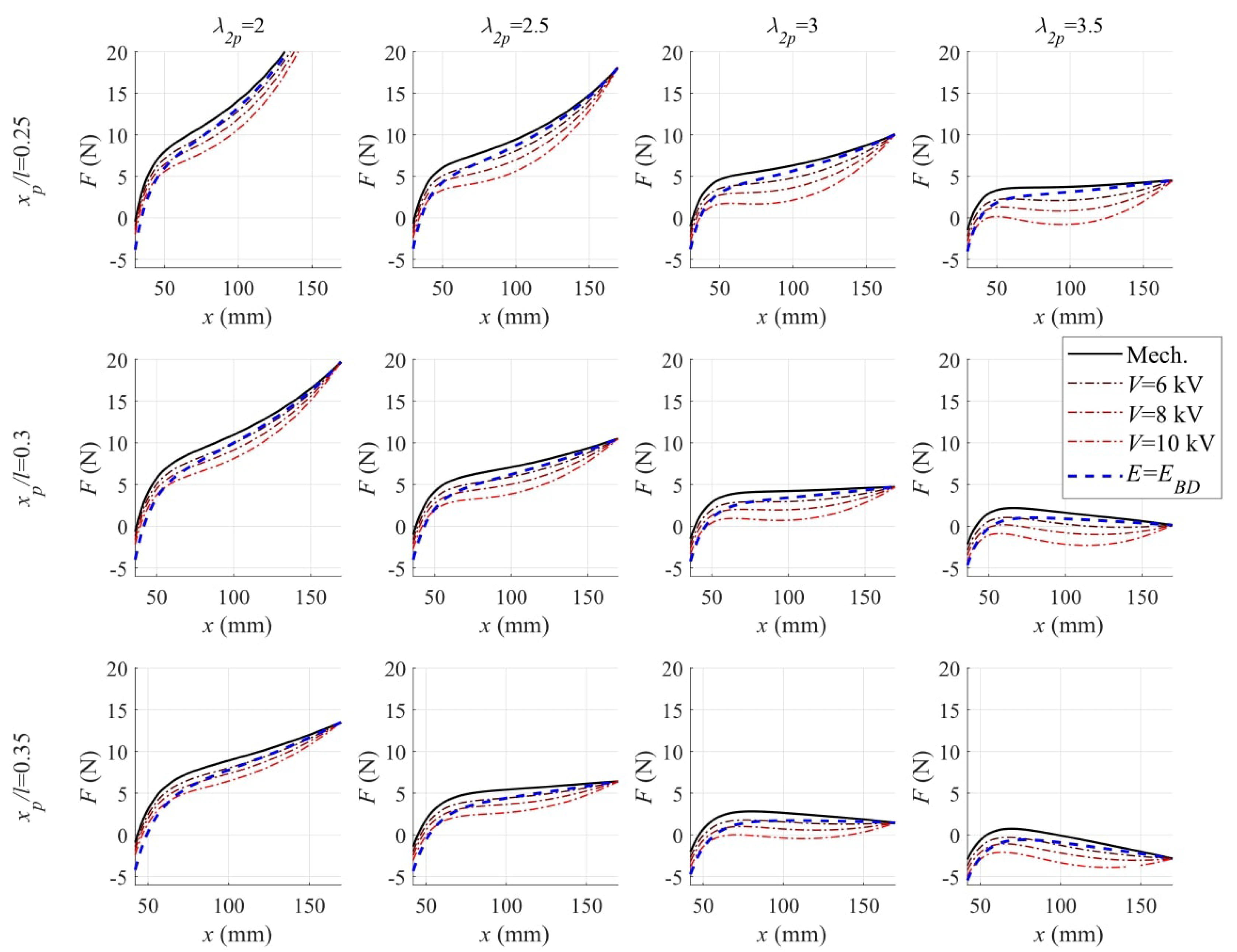
With reference to the parameters in Table 1, Figure 2 shows a map of the static actuator response for different choices of and . For each combination of the pre-stretch parameters, the figure shows the plot of the LS-DEA force-displacement characteristics at different voltages. The following considerations can be drawn:
- In correspondence with the low values of and , the LS-DEA has a stiff response (i.e., large slope of the force-displacement curves). As a consequence, the force variation achievable through electric activation in a given configuration x is small compared to the bias mechanical force required to hold the actuator in such a configuration.
- Increasing and provides an increase in the compressive stresses in the y direction and a consequent reduction in the actuator stiffness (in the x direction). As a result, the mechanical response curves assume a nearly-horizontal trend. This leads to an increase in the ratio of the electrostatic force variation over the mechanical biasing force (at fixed x) and in the nominal voltage-induced stroke (at fixed F).
- At large values of and , the characteristic curves have a negative slope over a significant portion of the range, hence potentially suffering from unstable response (unless the DEA is coupled with a positive-stiffness biasing element [14]).
The previous considerations prove that there exists a range of suitable choices for the pre-stretching parameters, which implement an intrinsic compensation of the actuator elastic stiffness, potentially leading to large blocking forces or actuation strokes while guaranteeing a stable behavior.
4. Prototype and Characterization Setup
This section presents an LS-DEG prototype and a setup that were employed for the experimental demonstration and characterization of the proposed stiffness compensation principle illustrated in the previous sections. Different LS-DEA prototypes were developed by varying the DE membrane pre-stretches within the useful range identified in Section 3, so as to implement an intrinsic compensation of the DE membrane mechanical stiffness. The experimental setup was designed in order to make it possible to implement the following set of testing conditions:
- isopotential tensile tests, aimed at mapping the quasi-static force-displacement characteristic of the prototype actuators at different levels of constant applied voltage.
- isometric tests, aimed at measuring the actuator blocking force in different configurations.
- isotonic tests, aimed at measuring the LS-DEA actuation stroke in the presence of constant applied forces.
4.1. LS-DEA Prototype Manufacturing
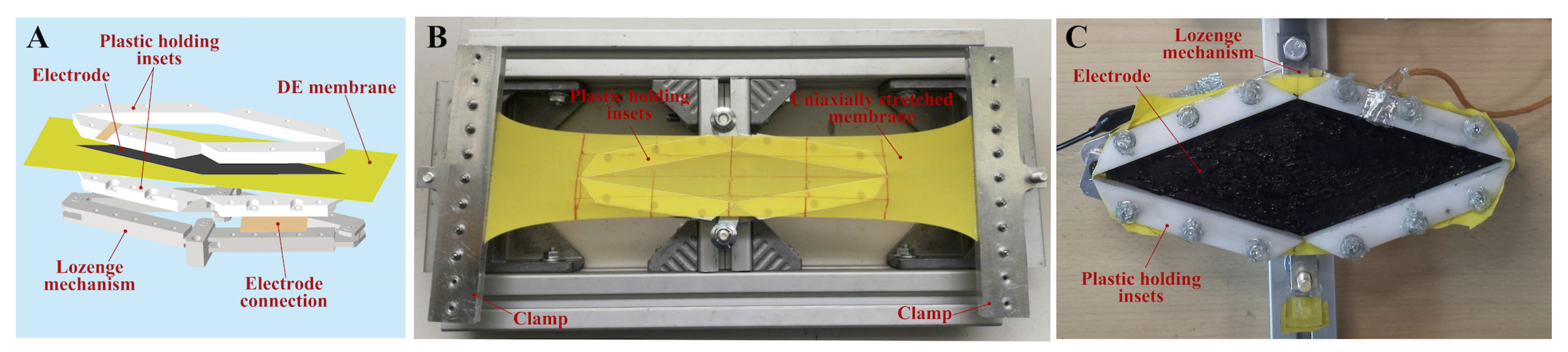
For the purpose of experimental demonstration, we built a lozenge mechanism equipped with a holding structure for the DE membrane that was designed according to a multi-layer architecture shown in Figure 3A. The bottom layer of the structure consisted of an aluminum four bar mechanism, with links of equal lengths mm and with joints implemented with low-friction rolling bearings. Each link housed a couple of plastic insets (made of Delrin®) between which the DE membrane was sandwiched. The shape of the insets was properly designed so as to guarantee that the DE membrane was uniformly stretched and followed the deformation kinematics discussed in Section 2. The perimeter of the DE membrane was secured to the plastic insets by means of a bi-adhesive tape (BIPAN by PAN Film), which prevented slippage between the rubber and the plastic surfaces. For the sake of laboratory testing, compliant electrodes were realized coating the DE membrane faces with a carbon conductive grease (MG-Chemicals 846). Connections between compliant electrodes and the circuit wires were created through aluminum tape located at the perimeter of the active membrane portion. In order to minimize the current leakage of the power electronics, wiring between the LS-DEA and the power supply was encapsulated via thick layers of acrylic tape.
Assembly of the DE membrane on the lozenge mechanism was carried out by locking the mechanism in a selected pre-stretch configuration (identified by ), stretching the DE membrane uniaxially via rigid clamps (see [30]), and aligning it with the lozenge mechanism along the y direction. Different LS-DEA prototypes were built using DE membranes with different uniaxial pre-stretches. A picture of the pre-stretching operation is shown in Figure 3B, while a picture of the final LS-DEA assembly (with painted carbon grease electrodes) is in Figure 3C. The final assembled prototype had a mass of approximately 630 g, almost entirely ascribable to the lozenge mechanism and the holding frame.
Three different LS-DEA designs were implemented and tested, whose nominal features (pre-stretch parameters and mass of the active DE material, assuming a density of 1000 kg/m3) are reported in Table 2.
It is worth remarking that the prototypes developed here represents a sub-optimal implementation simply aimed at providing the proof-of-concept of the SR LS-DEA. In particular, the employment of carbon grease for the compliant electrodes represented a practical experimental choice, but it is not a credible solution for the development of stable long-lasting prototypes. Furthermore, the employed lozenge mechanism and holding frame do not represent a suitable choice for a final-use LS-DEA due to their bulky architecture and large weight/inertia, which is expected to affect the actuator frequency response negatively. Future research effort will be dedicated to the development of scalable lightweight LS-DEA prototypes. Active membranes will be implemented as composite structures made of SR DE layers and conducting polymer electrode layers. A fully polymeric version of the lozenge mechanism will be investigated, in which the mechanism links are implemented via plastic structures and rigid hinges/bearings are replaced by flexure hinges, as proposed in [22].
4.2. Experimental Setups and Procedures
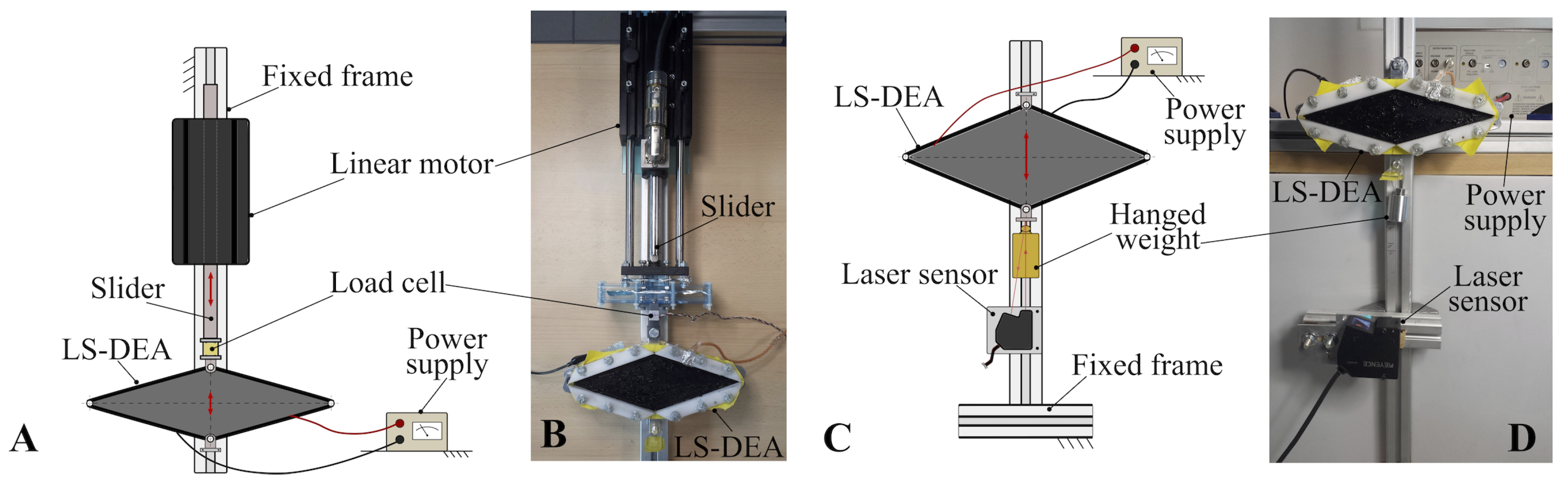
Two test-benches were built, one for the implementation of isopotential and isometric tests (Figure 4A,B) and one for the implementation of isotonic tests (Figure 4C,D).
In the first setup (Figure 4A), the LS-DEA prototype was laid horizontally, with one joint rigidly secured on a fixed frame and the opposite joint (end-effector) connected to the slider of a brushless linear motor (P01-37x120F/200x280-HP by LinMot), whose stator was attached to the fixed frame. The LS-DEA was electrically driven by a high-voltage amplifier (10/10B-HS by TREK), which allowed the implementation of user-defined voltage profiles on the device. A picture of the assembled setup for isopotential and isometric tests is shown in Figure 4B.
Isopotential tests were performed prescribing a user-defined cyclic displacement to the LS-DEA end-effector with the motor and measuring the LS-DEA force at different positions in the presence of a constant voltage difference on the LS-DEA electrodes. The LS-DEA end-effector displacement was measured with the motor’s integrated encoder, while the LS-DEA prototype force was measured with a load cell (Rb-Phi-118 with RB-Onl-38 amplifier by RobotShop) mounted in series to the LS-DEA and the slider. In the isopotential tests described in this article, the LS-DEA prototypes were subject to sinusoidal displacements. For each prototype, different tests were carried out, varying the deformation amplitude and the applied voltage level. In order to remove the Mullins effect [31], specimens under investigation were cycled 10 times between the same deformation limits: the Mullins effect disappeared above the fifth cycle. The last cycle was then taken as the stabilized response.
Isometric tests were carried out by locking the LS-DEA in a selected deformed configuration, applying an arbitrary voltage profile on the electrodes, and measuring the resulting force variations. Isometric tests were performed applying sinusoidal voltage profiles with different frequencies, considering different blocking positions for the LS-DEA. In each test, the membrane was taken from an initial position (in which its elastic force was equal to zero) to the blocking position with the motor. A time of approximately 30 s was then allowed after the achievement of the blocking position before voltage application, in order for the LS-DEA force to relax (due to rubber inelasticity) and to reach a stable value.
In the isotonic test setup (Figure 4D), the LS-DEA was secured to a vertical fixed frame through one of its joints. The opposite joint (end-effector) was free to move, and it held a hung mass. Tests were carried out prescribing arbitrary voltage profiles on the actuator through the power supply and measuring the resulting end-effector displacements through a laser displacement sensor (LK-G152 by Keyence). In the tests, the LS-DEA was subject to sinusoidal voltage excitation. Different tests were performed, changing the excitation frequency and the value of the hung mass. A time of approximately 60 s was allowed between consecutive tests (with different frequencies) in order for the LS-DEA to reach a stable state.
In the different tests, a real-time target machine by SpeedGoat, running MATLAB Realtime software environment, was used to control the experimental equipment (i.e., the linear motor and the voltage amplifier) and to acquire data from the sensors (motor encoder, load cell, power supply integrated voltmeter, laser sensor). Data were acquired at a sampling frequency of 10 kHz.
5. Experimental Tests and Results
With reference to the setup and LS-DEA prototypes presented in Section 4, this section presents an overview and discussion of the experimental results for the different classes of tests including isopotential, isometric, and isotonic conditions. Different LS-DEA prototypes (Table 2) were characterized providing evidence of the SR LS-DEA capability to accomplish actuation tasks and validating the design procedure illustrated in Section 3.
5.1. Isopotential Tests
Results of isopotential tests provide a measure of the LS-DEA steady-state response, allowing identifying suitable operating ranges where the actuator exhibits a low stiffness (flat force-displacement response) and a stable behavior and to make forecasts on the potential actuation performance.
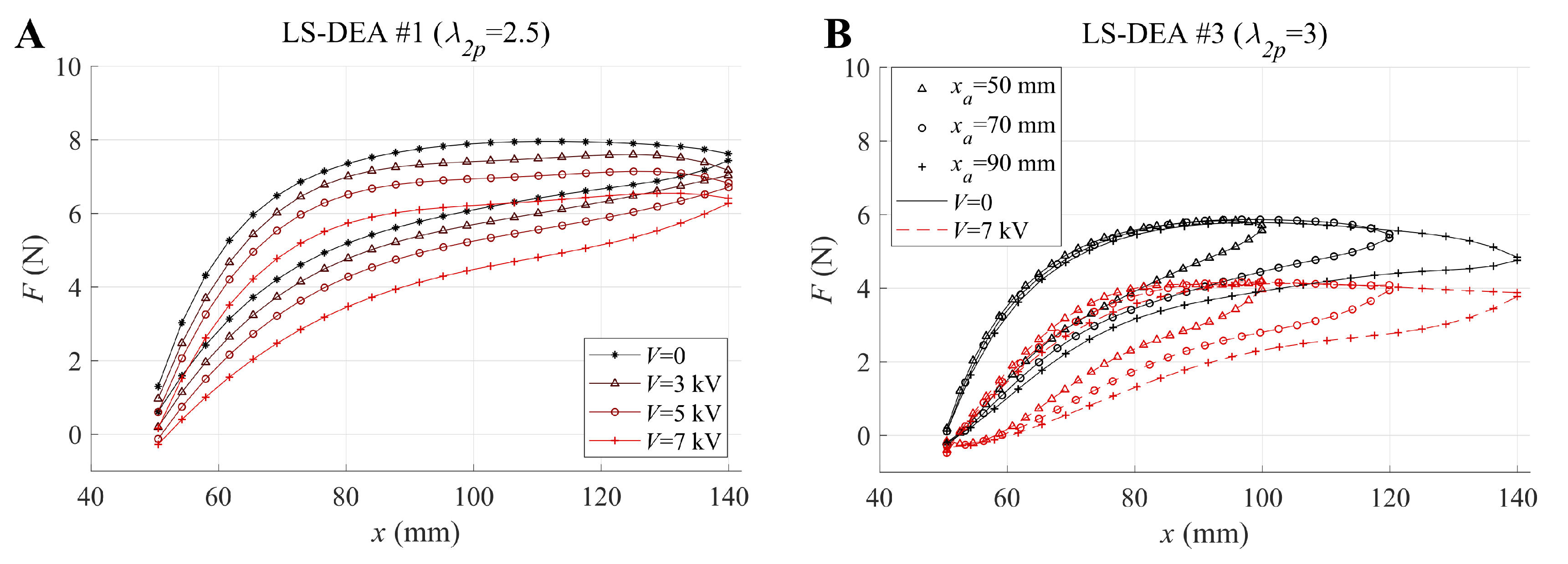
Isopotential tests were performed on all of the LS-DEA geometries presented in Table 2. Different tests were performed using a constant frequency Hz for the prescribed displacements. At such a low frequency, the actuator behavior can be considered quasi-static, the inertial forces being negligible with respect to elastic and electrostatic forces. The displacement amplitude (crest-to-trough) was varied throughout the different tests within the following set of values: 50, 70, and 90 mm, using a value of mm for the minimum LS-DEA aperture in each test. For each amplitude value, different tests were performed with different values of the prescribed electric potential, in the range 0–7 kV. The maximum considered voltage was chosen to guarantee a wide safety margin with respect to the electrical breakdown condition (see Figure 2).
With reference to tests on prototype LS-DEA #1 and to an amplitude of mm, Figure 5A shows the force-displacement responses registered at different voltages.
The following can be observed:
- Consistent with the design assumptions, the force-displacement responses show a nearly-flat trend (i.e., a low value of the actuator stiffness) over a significant portion of the considered working range.
- Applying voltages within the considered range produces significant variations in the force-displacement response of the actuator. Based on these measurements, electrically-induced force variations of up to 2 N might potentially be obtained, assuming to lock the actuator at intermediate positions within the working range.
- The LS-DEA specimen has an inelastic response, due to the SR viscosity and hysteresis, as observed by [3]. A quantitative analysis of the associated dissipation is presented in the following.
With reference to prototype LS-DEA #3, Figure 5B compares the prototype force-displacement response at different values of the maximum deformation for purely mechanical tests () and at the maximum applied voltage ( kV). Although the prototype cyclic response naturally depends on the maximum deformation amplitude, the sample showed a repeatable force-deformation trend, independent of the displacement amplitude, during the extension phase. In the presence of large voltages, the electrostatic stresses caused the material to lose mechanical tension and the actuator force to fall to zero at small values of coordinate x, close to .
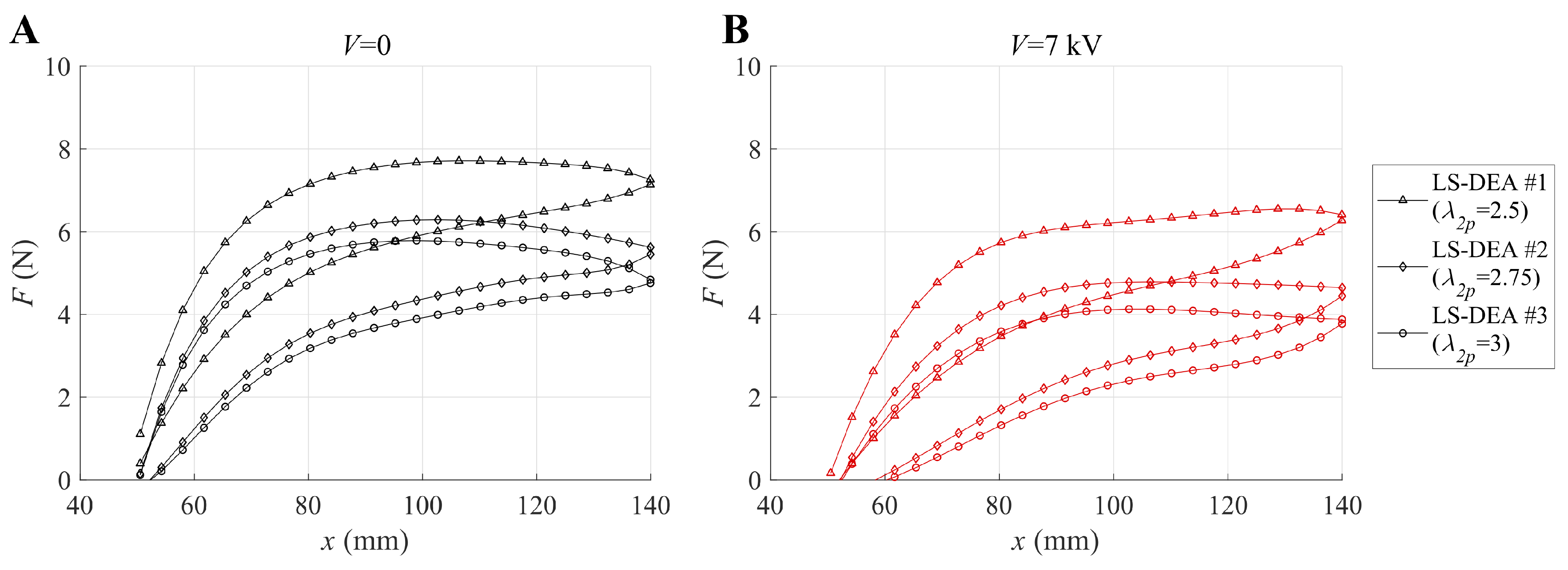
A comparison of the isopotential response of the different LS-DEA prototypes (featuring different pre-stretches) is shown in Figure 6, for the two cases with applied voltage equal to 0 (Figure 6A) and 7 kV (Figure 6B). In the considered range of values, increasing the transversal pre-stretch leads to a progressive reduction in the LS-DEA mechanical stiffness and, hence, a reduction in the LS-DEA restoring force. Interestingly, the different branches (loading-unloading) of the force-displacement responses have a monotonic increasing trend in the prototype LS-DEA #1 (featuring the lowest pre-stretch), whereas they show a decreasing trend (negative stiffness) at large values of x for the other two prototypes (with larger transversal pre-stretch). Such a negative stiffness response represents a potential benefit in applications in which the LS-DEA is coupled to stiff mechanical systems, but it might lead to instability issues in the presence of highly variable or randomly applied loads.
The presented isopotential test results suggest that the LS-DEA made of SR is subject to a relevant amount of hysteresis. An estimate of the hysteresis losses associated with the LS-DEA samples’ cyclic stretching is presented in Table 3. With reference to isopotential tests with mm, the hysteresis loss was calculated as the ratio of the energy dissipated in a tensile cycle (i.e., the area enclosed by the stabilized force-displacement curve) and the mechanical work spent to achieve maximum deformation (i.e., the area subtended by the loading curve over the entire deformation range). Hysteresis losses over 20% and up to 45% were recorded in the different isopotential tests. For the same SR material, hysteresis losses in the range 9–12% were reported in [3] for pure-shear tests conducted over a wide range of cyclic operating stretches and strain rates with no applied voltage. In order to understand the origin of the higher hysteresis losses measured in the present tests, let us ideally compare an LS-DEA sample and a pure-shear DE sample that, in a reference configuration, have the same longitudinal and transversal stretches (thus, the same stresses). Owing to the peculiar LS-DEA kinematics (namely, the concurrent contribution of the longitudinal and transversal stresses on the total force), the resulting longitudinal force (per unit cross-section surface of the DE membrane) of the LS-DEA in the actuation direction is lower than that of the pure-shear sample. As a result, the mechanical work (per unit elastomer volume) required to accomplish a given variation in the longitudinal stretch (i.e., the input mechanical energy density) is larger in the pure-shear case. The dissipated mechanical energy density due to hysteresis/viscosity is, in contrast, similar for the two kinematics, or slightly larger in the LS-DEA case (where both the stress variations in the x and y directions contribute to mechanical losses). This naturally results in larger values of the hysteresis loss in the LS-DEA, compared to a pure-shear system. In other words, the effect of mechanical stiffness reduction introduced by the transversal stresses in the LS-DEA has the drawback of leading to an increase in the weight of the mechanical losses on the actuator energy balance. Table 3 confirms that increasing the transversal pre-stretch leads to an increase in the hysteresis loss, due to the resulting decrease in the total mechanical stiffness. Similarly, increasing the voltage in isopotential tensile tests leads to an increase in hysteresis loss, as a result of a decrease in the actuator stiffness due to the Maxwell stress.
In actuation tasks, large hysteresis might lead to a significant dissipation of the supplied electrical energy input, limiting the producible useful mechanical energy output. Moreover, the hysteretic behavior might introduce parasitic effects (such as stress relaxation and equilibrium position drift), which are scarcely predictable and may complicate the actuator controllability. A possible solution to overcome potential controllability issues in SR LS-DEAs is the development of advanced control strategies, based on comprehensive numerical models including the effect of electro-mechanical losses [32] or on machine learning techniques [33].
Finally, it is worth noticing that the experimental force-displacement curves measured in isopotential tests (Figure 5 and Figure 6) fall within the ranges identified in Figure 2, both in terms of trends and numerical values, despite the uncertainties in the actual values of the prototypes features (e.g., pre-stretches) due to the employed manual manufacturing procedures. The presented mathematical model can thus be employed as an effective design tool to identify suitable combinations of the design ranges aimed at achieving a desired response and can be used as an initial framework to develop advanced controls.
5.2. Isometric Tests
Isometric tests were conducted by commanding time-varying electrical activation of the DEA while keeping the position of the lozenge-shaped mechanisms fixed in prescribed configurations. In these conditions, it was possible to observe the electromechanical response of the DEA without the contribution of the inertia of the four-bar mechanism.
Different isometric tests were performed, using a sinusoidal voltage excitation with an amplitude of 6 kV and frequency f in the range 1–10 Hz. It is worth noticing that, since the electrostatic component of the LS-DEA force ( in Equation (5)) depends on the squared voltage, the resulting LS-DEA force variations had twice the frequency of the prescribed voltage variations (i.e., in the range of 2–20 Hz). The upper bound of the frequency range used in the tests was related to setup limitations (namely, the maximum current that the connections between the compliant electrodes and the circuit wiring could safely withstand). It is worth remarking that such a frequency covers a significant portion of the typical/expected working range for DEAs operating at large actuation strains [3,34].
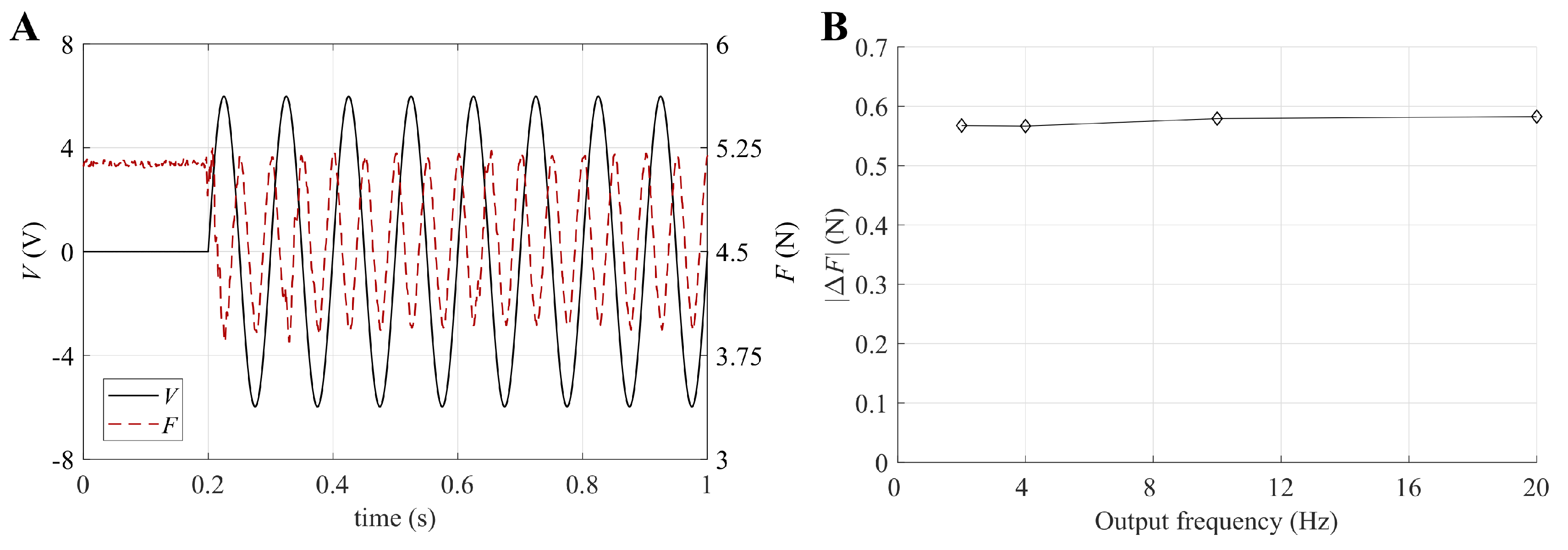
With reference to prototype LS-DEA #3 and to blocking position mm, Figure 7A shows the time-series of the force variation generated by an electrical excitation with Hz. As expected, the LS-DEA force was minimum when the voltage was maximum (positive) or minimum (negative), while it was maximum when the voltage was equal to zero. No phase shift between the force troughs and the voltage maxima/minima was practically present, and a minimum force approximately equal to the initial LS-DEA force (before electrical activation) was reached at each cycle. This proves that, in the considered working frequency range, electrical dynamics can be considered approximately instantaneous. This observation is confirmed by Figure 7B, which, with reference to the same LS-DEA sample, shows that the cyclic crest-to-trough force variation was practically independent of the force fluctuation frequency. This latter result also suggests that the DE material properties (e.g., the dielectric constant) do not significantly vary within the considered frequency range, thus allowing the achievement of constant blocking forces over a wide frequency range.
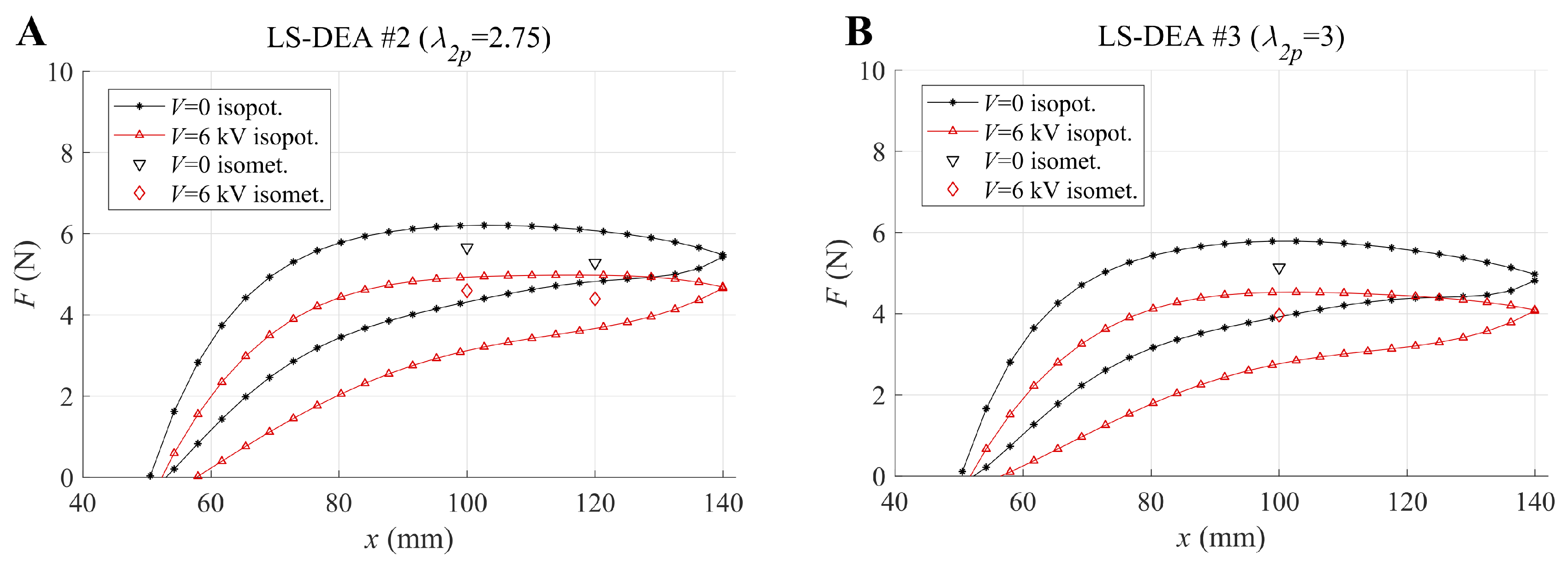
The results obtained in the isometric tests can be compared with those from isopotential tests. Figure 8 shows the isopotential curves at and kV and the experimental measurements (at the same voltages) obtained in the isometric tests, for prototypes LS-DEA #2 (Figure 8A) and LS-DEA #3 (Figure 8B), respectively. In the plots, the isometric forces in the electrically active state were calculated as the average over the different testing frequencies, due to the low variability of the electrostatic force with the frequency.
The data show that the force measured in isometric tests falls between the loading and the unloading curves of the corresponding tensile cycle, i.e., it is lower than the force measured during the extension phase in the isopotential tests. This is due to the time allowed in isometric tests after the achievement of the blocking position (prior to the voltage application), which causes a relaxation in the LS-DEA membrane force. The electrically-induced force variation in isometric tests is consistent with the shift between the isopotential curves at and kV, hence confirming the capability of the isopotential maps to predict the LS-DEA performance in blocking conditions reasonably.
5.3. Isotonic Tests
Isotonic tests are an effective tool to evaluate a transducer’s performance against a standard task (e.g., lifting a load, making work against a constant force) and to evaluate its dynamics and working bandwidth. For the specific case of the SR LS-DEA, given the significant hysteresis losses observed in isopotential tests, isotonic tests are especially crucial to understand the actual limits in terms of the convertible energy.
For isotonic tests, attention was restricted to LS-DEA #1, i.e., the design with the lowest value of the transversal pre-stretch. Based on the isopotential test results shown in Figure 6, this implementation was expected to feature a stable response (i.e., positive slope of the static curves) at constant applied forces over the whole operating range, differently from designs LS-DEA #2 and LS-DEA #3 (which might behave unstably at large loads). Experiments were performed considering three different scenarios: (1) LS-DEA subject to the action of its own weight, with no additional hung mass; (2) LS-DEA with a hung mass g; and (3) LS-DEA with a hung mass g. The resulting applied forces in the three cases were (1) N (equal to 1/2 of the total actuator weight), (2) N, and (3) N. In each test, the voltage was cyclically varied between 0 and 5 kV following a sinusoidal profile. Different tests were performed varying the frequency in the range 1–4 Hz.
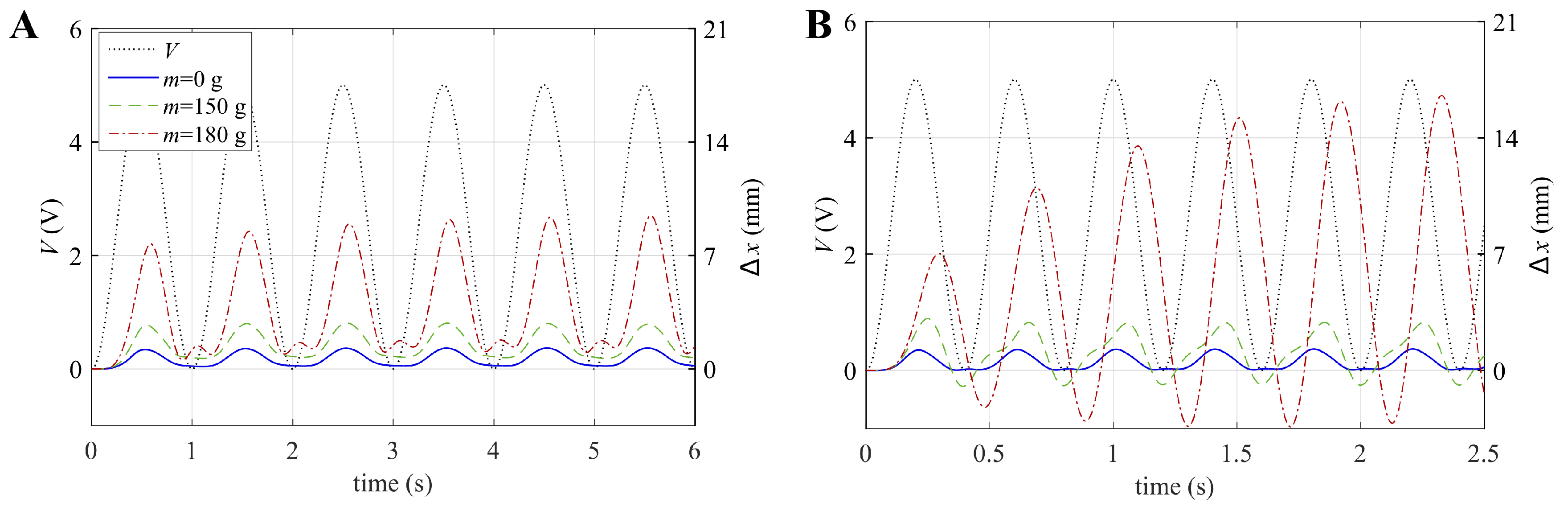
With reference to two tests with different values of the electric excitation frequency, Figure 9 shows the time series of the LS-DEA displacement induced by the electric excitation (the initial equilibrium position x and the slow position drifts due to rubber stress relaxation were subtracted from the time series to facilitate the comparison of different scenarios). The following could be observed:
- At the lowest frequency (Figure 9A), the actuator operation can be considered quasi-static. As a consequence, the LS-DEA displacement was in phase with the electrical excitation. At the time instants where the voltage equaled zero, the device reached a position that approximately equaled the initial equilibrium position (i.e., ). The oscillation amplitude increased with the applied load (hung mass), owing to the lower stiffness of the LS-DEA at large applied forces (see the slope of the curves in Figure 6)
- The increase in the oscillation amplitude was maximum in the case 180 g, while it was practically negligible for . This is easily explained in terms of the actuator natural frequency in the different scenarios. The higher the applied weight on the device, the lower the natural frequency is, due to two combined effects: (1) the increase in the actuator inertia; (2) the decrease in the LS-DEA stiffness. In the case , the actuator still behaved in a quasi-static way, whereas in the case g, it showed a nearly-resonant behavior, as demonstrated by the significant phase shift between the excitation signal and the displacement.
- The displacement time series significantly divert from the sinusoidal trend, owing to the highly nonlinear LS-DEA response and to the presence of low-amplitude parasitic oscillation modes (e.g., rotation above the lozenge mechanism fixed hinge), which led to the presence of multiple peaks within the same oscillation.
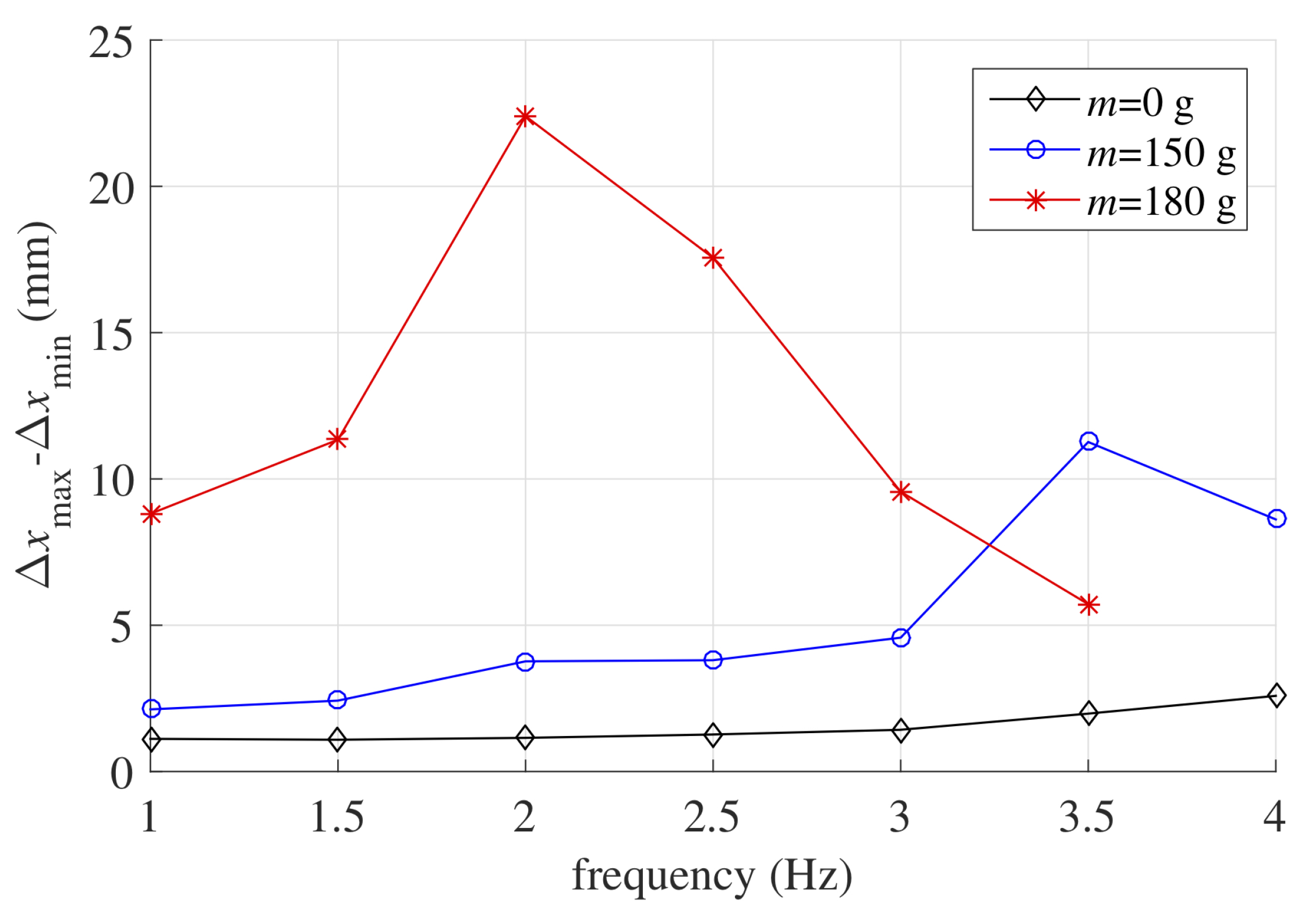
An overview of the LS-DEA dynamical response over the considered frequency range is shown in Figure 10. The figure reports the total oscillation amplitude measured at the different frequencies.
In the scenarios with larger applied mass, the resonance frequency (at which the oscillation amplitude is maximum) falls within the investigated frequency range, namely around Hz for g and Hz for g. In the case with no hung mass, the natural frequency lies above the upper bound of the considered range, as shown by the slight increase in the oscillation amplitude with frequency. The maximum amplitude was reached in the presence of the largest mass, as in this case, the equilibrium position of the system falls in a region where the working range is characterized by lower mechanical stiffness. In this context, a maximum stroke of 22 mm was reached, corresponding to 18% the lozenge mechanism side length.
Remarkably, despite the large hysteresis observed in isopotential tests, the LS-DEA was capable of effectively accomplishing the isotonic actuation task, providing an energy density (gravitational energy variation of the hung mass in a semi-oscillation per unit DE mass) of up to 20 mJ/g in quasi-static conditions ( Hz) and of 50 mJ/g around the resonance condition. The previous figures significantly increase to 50 mJ/g at 1 Hz and 140 mJ/g at resonance if the gravitational energy variation associated with the lozenge mechanism are also considered, leading to results comparable with those demonstrated with soft acrylic DEs [34,35]. Remarkably, this result was achieved with a DEA embodiment that did not make use of any external stiffness cancellation mechanical element, as opposed to most DEA layouts based on high-modulus elastomers (e.g., silicones) proposed so far [14,15].
Large margins of improvement for the SR LS-DEA are possible, both in terms of convertible energy density and operating bandwidth, if an optimized lightweight design for the system (e.g., based on a fully polymeric compliant frame) is pursued.
6. Conclusions
This paper presented for the first time the design and proof-of-concept of a Dielectric Elastomer Actuator (DEA) based on a styrene-based Synthetic Rubber (SR), namely Theraband Yellow 11726. Compared to widespread acrylic elastomers (e.g., VHB by 3M), the considered rubber is characterized by higher dielectric strength, resilience, and physical stability, which make it potentially suitable for the development of reliable DE transducers. Compared to silicone DEs, this material is widespread and has a lower cost. Similar to silicone elastomers, a drawback of SR is its large elastic stiffness, which potentially compromises its performance in actuation tasks, unless suitable designs are pursued to implement stiffness cancellation mechanisms.
Here, a design solution was proposed that relies on the so-called Lozenge-Shaped DEA (LS-DEA) principle. The LS-DEA is a one-degree-of-freedom linear actuator that consists of an active dielectric elastomer membrane clamped to the rigid links of a four bar mechanism with equal length links (i.e., a lozenge mechanism). Biaxially pre-stretching the active membrane in the longitudinal actuation direction and in the transversal direction allows the implementation of LS-DEAs with different mechanical stiffness and force-displacement response. Based on an analytical model, we showed that, by properly selecting the material pre-stretch, it is possible to obtain an LS-DEA with arbitrarily low elastic stiffness with no need for further negative-spring mechanisms, hence providing a design solution potentially capable of achieving large deformations in response to voltage inputs. We then presented an experimental validation of the proposed design concept through three classes of experiments: (1) isopotential experiments, aimed at measuring the force-displacement steady-state response in the presence of different applied voltages; (2) isometric tests, aimed at measuring the blocking force in the presence of dynamically-varying electric excitation; and (3) isotonic tests, aimed at evaluating the actuation performance (achieved strains and converted energy density) in the presence of constant applied loads. Different LS-DEA prototypes were realized, in order to assess the effect of varying the design parameters (i.e., pre-stretches) in the device response. Experimental results showed that the SR LS-DEA achieves a nearly-flat force-displacement response (i.e., a low mechanical stiffness) within the pre-stretch range forecast by the model. As a result, the developed experimental prototypes resulted in being capable of operating effectively in standard actuation tasks, showing a remarkable bandwidth over 20 Hz in blocking (isometric) conditions and a convertible energy density of up to 140 mJ/g with a stroke equal to 18% of the lozenge side length in isotonic operation. The experimental results highlighted that a potential criticality of the proposed concept lies in the large mechanical hysteresis losses associated with the peculiar deformation kinematics of the LS-DEA. Such an issue might lead to undesired behaviors (e.g., time-varying position in the presence of a constant force and vice versa) and might hence require more advanced control strategies aimed at guaranteeing a stable and repeatable response.
It is worth remarking that the experiments were carried out with the aim of providing an initial proof-of-concept of the SR LS-DEA. In effect, the experimental prototypes described here relies on a non-optimal mechanical design for the lozenge mechanism, based on bulky and heavy components. Future works will thus focus on the development of lightweight LS-DEAs with compliant mechanisms based on flexure hinges. Besides providing a scalable solution for end-use applications, such an alternative design will expectedly lead to improved performance in terms of the useful convertible energy density and the operating bandwidth. Further significant improvements can be finally obtained working at the level of the SR elastomer manufacturing process, with the aim of delivering a high-quality film free from defects and process-dependent parameter variability.
Author Contributions
G.M., R.V., G.B., and M.F. conceived of the idea of the device. G.M. in collaboration with L.S. and M.F. designed the setups and conducted the experiments. L.A. and R.V. did the characterization test on the elastomeric materials. All the authors contributed to the mathematical modeling of the actuator, to the analysis of the experimental results, and to the writing. All authors read and agreed to the published version of the manuscript.
Funding
M.F. and L.S. received funding from the Italian Ministry of Education, University and Research (MIUR) under the Program Department of Excellence, awarded by the Department of Industrial Engineering of the University of Trento. G.B. received funding form the University of Genova under the program COSMET (COmpliant Shell-based mechanisms for MEdical Technologies). G.M. and L.A. received funding from the Region of Tuscany (Italy) under the project EOLO(FAR FAS 2014-A).
Acknowledgments
The authors would like to thank Francesco Damiani for his technical support and Cheros Engineering for providing some of the components of the setup.
Conflicts of Interest
The funders had no role in the design of the study; in the collection, analyses, or interpretation of data; in the writing of the manuscript; nor in the decision to publish the results.
Abbreviations
The following abbreviations are used in this manuscript:
| SR | Synthetic Rubber |
| LS-DEA | Lozenge-Shaped Dielectric Elastomer Actuator |
| DE | Dielectric Elastomer |
| DEA | Dielectric Elastomer Actuator |
References
- Carpi, F.; Anderson, I.; Bauer, S.; Frediani, G.; Gallone, G.; Gei, M.; Graaf, C.; Jean-Mistral, C.; Kaal, W.; Kofod, G.; et al. Standards for dielectric elastomer transducers. Smart Mater. Struct. 2015, 24, 105025. [Google Scholar] [CrossRef] [Green Version]
- Carpi, F. Electromechanically Active Polymers: A Concise Reference, 1st ed.; Springer International Publishing: Berlin/Heidelberg, Germany, 2016. [Google Scholar]
- Chen, Y.; Agostini, L.; Moretti, G.; Fontana, M.; Vertechy, R. Dielectric elastomer materials for large-strain actuation and energy harvesting: A comparison between styrenic rubber, natural rubber and acrylic elastomer. Smart Mater. Struct. 2019, 28, 114001. [Google Scholar] [CrossRef]
- Gu, G.Y.; Zhu, J.; Zhu, L.M.; Zhu, X. A survey on dielectric elastomer actuators for soft robots. Bioinspir. Biomimetics 2017, 12, 011003. [Google Scholar] [CrossRef] [PubMed]
- Shintake, J.; Rosset, S.; Schubert, B.; Floreano, D.; Shea, H. Versatile soft grippers with intrinsic electroadhesion based on multifunctional polymer actuators. Adv. Mater. 2016, 28, 231–238. [Google Scholar] [CrossRef] [PubMed]
- Babiç, M.; Vertechy, R.; Berselli, G.; Lenarçiç, J.; Parenti Castelli, V.; Vassura, G. An electronic driver for improving the open and closed loop electro-mechanical response of Dielectric Elastomer actuators. Mechatronics 2010, 20, 201–212. [Google Scholar] [CrossRef]
- Lee, B.Y.; Kim, J.; Kim, H.; Kim, C.; Lee, S.D. Low-cost flexible pressure sensor based on dielectric elastomer film with micro-pores. Sens. Actuators A Phys. 2016, 240, 103–109. [Google Scholar] [CrossRef]
- Zhu, Y.; Tairych, A.; Rosset, S.; Anderson, I.A. An approach to validate the design and fabrication of dielectric elastomer tactile sensor. In Electroactive Polymer Actuators and Devices; SPIE: Bellingham, DC, USA, 2019. [Google Scholar]
- Binh, P.C.; Ahn, K.K. Performance optimization of dielectric electro active polymers in wave energy converter application. Int. J. Precis. Eng. Manuf. 2016, 17, 1175–1185. [Google Scholar] [CrossRef]
- Moretti, G.; Herran, M.S.; Forehand, D.; Alves, M.; Jeffrey, H.; Vertechy, R.; Fontana, M. Advances in the development of dielectric elastomer generators for wave energy conversion. Renew. Sustain. Energy Rev. 2020, 117, 109430. [Google Scholar] [CrossRef]
- Kovacs, G.; Düring, L.; Michel, S.; Terrasi, G. Stacked dielectric elastomer actuator for tensile force transmission. Sens. Actuators A Phys. 2009, 155, 299–307. [Google Scholar] [CrossRef]
- Berselli, G.; Vertechy, R.; Vassura, G.; Parenti-Castelli, V. Optimal synthesis of conically shaped dielectric elastomer linear actuators: Design methodology and experimental validation. IEEE/ASME Trans. Mechatron. 2011, 16, 67–79. [Google Scholar] [CrossRef]
- Jean-Mistral, C.; Jacquet-Richardet, G.; Sylvestre, A. Parameters influencing fatigue life prediction of dielectric elastomer generators. Polym. Test. 2020, 81, 106198. [Google Scholar] [CrossRef]
- Hodgins, M.; York, A.; Seelecke, S. Experimental comparison of bias elements for out-of-plane DEAP actuator system. Smart Mater. Struct. 2013, 22, 094016. [Google Scholar] [CrossRef]
- Hau, S.; Bruch, D.; Rizzello, G.; Motzki, P.; Seelecke, S. Silicone based dielectric elastomer strip actuators coupled with nonlinear biasing elements for large actuation strains. Smart Mater. Struct. 2018, 27, 074003. [Google Scholar] [CrossRef]
- Kaltseis, R.; Keplinger, C.; Koh, S.J.A.; Baumgartner, R.; Goh, Y.F.; Ng, W.H.; Kogler, A.; Tröls, A.; Foo, C.C.; Suo, Z.; et al. Natural rubber for sustainable high-power electrical energy generation. RSC Adv. 2014, 4, 27905–27913. [Google Scholar] [CrossRef] [Green Version]
- Moretti, G.; Fontana, M.; Vertechy, R. Parallelogram-shaped dielectric elastomer generators: Analytical model and experimental validation. J. Intell. Mater. Syst. Struct. 2015, 26, 740–751. [Google Scholar] [CrossRef] [Green Version]
- Vertechy, R.; Fontana, M. Electromechanical characterization of a new synthetic rubber membrane for dielectric elastomer transducers. In Electroactive Polymer Actuators and Devices (EAPAD) 2015; International Society for Optics and Photonics: Bellingham, WA, USA, 2015; Volume 9430, p. 94300K. [Google Scholar]
- Berselli, G.; Guerra, A.; Vassura, G.; Andrisano, A.O. An engineering method for comparing selectively compliant joints in robotic structures. IEEE Trans. Mechatron. 2014, 19, 1882–1895. [Google Scholar] [CrossRef]
- Youn, J.H.; Jeong, S.M.; Choi, Y.S.; Kyung, K.U. A soft tactile display using dielectric elastomer actuator for fingertip interaction. In Haptic Interaction; Kajimoto, H., Lee, D., Kim, S.Y., Konyo, M., Kyung, K.U., Eds.; Springer: Singapore, 2019; pp. 15–17. [Google Scholar]
- Weight, B.L.; Magleby, S.P.; Howell, L.L. Selection of compliant constant-force mechanisms based on stress and force criteria. In ASME IDETC-CIE International Design Engineering Technical Conferences and Computers and Information in Engineering Conference; American Society of Mechanical Engineers Digital Collection: New York, NY, USA, 2002; pp. 51–63. [Google Scholar]
- Plante, J.; Dubowsky, S. On the properties of dielectric elastomer actuators and their design implications. Smart Mater. Struct. 2007, 16, S227. [Google Scholar] [CrossRef]
- Plante, J.S.; Dubowsky, S. On the performance mechanisms of dielectric elastomer actuators. Sens. Actuators A Phys. 2007, 137, 96–109. [Google Scholar] [CrossRef]
- Vertechy, R.; Berselli, G.; Parenti Castelli, V.; Vassura, G. Optimal design of lozenge-shaped dielectric elastomer linear actuators: Mathematical procedure and experimental validation. J. Intell. Mater. Syst. Struct. 2010, 21, 503–515. [Google Scholar] [CrossRef]
- Dorfmann, L.; Ogden, R.W. Nonlinear Theory of Electroelastic and Magnetoelastic Interactions; Springer: Berlin/Heidelberg, Germany, 2014. [Google Scholar]
- Moretti, G.; Fontana, M.; Vertechy, R. Model-based design and optimization of a dielectric elastomer power take-off for oscillating wave surge energy converters. Meccanica 2015, 50, 2797–2813. [Google Scholar] [CrossRef] [Green Version]
- Ogden, R.; Saccomandi, G.; Sgura, I. Fitting hyperelastic models to experimental data. Comput. Mech. 2004, 34, 484–502. [Google Scholar] [CrossRef] [Green Version]
- Elastosil Films Catalogue, Wacker. Available online: https://www.wacker.com/h/en-us/silicone-rubber/silicone-films/elastosil-film-2030/p/000038005 (accessed on 27 May 2020).
- Tröls, A.; Kogler, A.; Baumgartner, R.; Kaltseis, R.; Keplinger, C.; Schwödiauer, R.; Graz, I.; Bauer, S. Stretch dependence of the electrical breakdown strength and dielectric constant of dielectric elastomers. Smart Mater. Struct. 2013, 22, 104012. [Google Scholar] [CrossRef]
- Berselli, G.; Vertechy, R.; Fontana, M.; Pellicciari, M. An experimental assessment of the thermo-elastic response in acrylic elastomers and natural rubbers for application on electroactive polymer transducers. In ASME 2014 Conference on Smart Materials, Adaptive Structures and Intelligent Systems; American Society of Mechanical Engineers: New York, NY, USA, 2014. [Google Scholar]
- Harwood, J.; Mullins, L.; Payne, A. Stress softening in natural rubber vulcanizates. Part II. Stress softening effects in pure gum and filler loaded rubbers. J. Appl. Polym. Sci. 1965, 9, 3011–3021. [Google Scholar] [CrossRef]
- Rizzello, G.; Naso, D.; York, A.; Seelecke, S. Modeling, identification, and control of a dielectric electro-active polymer positioning system. IEEE Trans. Control Syst. Technol. 2014, 23, 632–643. [Google Scholar] [CrossRef]
- Wilson, E.D.; Assaf, T.; Pearson, M.J.; Rossiter, J.M.; Anderson, S.R.; Porrill, J. Bioinspired adaptive control for artificial muscles. In Conference on Biomimetic and Biohybrid Systems; Springer: Berlin/Heidelberg, Germany, 2013; pp. 311–322. [Google Scholar]
- Pelrine, R.; Kornbluh, R.; Pei, Q.; Joseph, J. High-speed electrically actuated elastomers with strain greater than 100%. Science 2000, 287, 836–839. [Google Scholar] [CrossRef]
- Carpi, F.; Bauer, S.; De Rossi, D. Stretching dielectric elastomer performance. Science 2010, 330, 1759–1761. [Google Scholar] [CrossRef]
Figure 1.
Layout and operating principle of an LS-DEA: Applying a voltage on the LS-DEA electrodes causes an expansion in the active membrane surface, corresponding to a variation in the lengths of the lozenge mechanism diagonals. The detail of the principal stretch directions acting on a material element is shown on the right.

Figure 2.
Analytically calculated force-displacement characteristic of the LS-DEA made of SR at different pre-stretches. Solid lines represent the purely elastic contribution; dashed-dotted lines represent the response in the presence of different applied voltages; and dashed lines represent the force at breakdown.

Figure 3.
(A) Exploded view of the experimental LS-DEA prototype. (B) DE membrane pre-stretching and installation on the lozenge mechanism. (C) Picture of the final LS-DEA assembly.
Figure 3.
(A) Exploded view of the experimental LS-DEA prototype. (B) DE membrane pre-stretching and installation on the lozenge mechanism. (C) Picture of the final LS-DEA assembly.

Figure 4.
Schematic (A) and picture (B) of the experimental setup for isopotential and isometric tests. Schematic (C) and picture (D) of the experimental setup for isotonic tests.
Figure 4.
Schematic (A) and picture (B) of the experimental setup for isopotential and isometric tests. Schematic (C) and picture (D) of the experimental setup for isotonic tests.

Figure 5.
(A) Stabilized force-displacement curves for LS-DEA #1 subject to cyclic displacements ( mm) at different voltages. (B) Stabilized force-displacement curves for LS-DEA #3 subject to cyclic displacements with different amplitudes: solid lines refer to tests in the absence of applied voltage, while dashed lines refer to tests with voltage kV.

Figure 6.
Stabilized force-displacement curves for three different LS-DEA prototypes (see Table 2) subject to cyclic displacements ( mm) at (A) kV and (B) kV.
Figure 6.
Stabilized force-displacement curves for three different LS-DEA prototypes (see Table 2) subject to cyclic displacements ( mm) at (A) kV and (B) kV.

Figure 7.
(A) Time series of the applied voltage and measured force for a test with excitation frequency of 10 Hz (output frequency of 20 Hz) and (B) electrically-induced force variation at different output frequencies for LS-DEA #3 () at blocking position mm.
Figure 7.
(A) Time series of the applied voltage and measured force for a test with excitation frequency of 10 Hz (output frequency of 20 Hz) and (B) electrically-induced force variation at different output frequencies for LS-DEA #3 () at blocking position mm.

Figure 8.
Comparison of experimental isopotential tensile cycles and isometric measurements at kV and kV for prototypes LS-DEA #2 (A) and LS-DEA #3 (B). Isolated markers refer to different isometric measurements at different voltages and blocking positions.
Figure 8.
Comparison of experimental isopotential tensile cycles and isometric measurements at kV and kV for prototypes LS-DEA #2 (A) and LS-DEA #3 (B). Isolated markers refer to different isometric measurements at different voltages and blocking positions.

Figure 9.
Time series of the applied voltage and measured displacement with different values of the constant applied force (hung mass) for excitation frequencies of (A) 1 Hz and (B) 2.5 Hz.
Figure 9.
Time series of the applied voltage and measured displacement with different values of the constant applied force (hung mass) for excitation frequencies of (A) 1 Hz and (B) 2.5 Hz.

Figure 10.
Crest-to-trough oscillation amplitude at different excitation frequencies in isotonic tests with different values of the hung mass.
Figure 10.
Crest-to-trough oscillation amplitude at different excitation frequencies in isotonic tests with different values of the hung mass.


Table 1.
Theraband Yellow 11726’s electro-mechanical properties [3].
Table 1.
Theraband Yellow 11726’s electro-mechanical properties [3].
| Property | Value |
|---|---|
| Unstretched thickness | m |
| Hyperelastic parameters | kPa, , kPa |
| Dielectric permittivity | F/m |
| Stretch-dependent breakdown electric field | |
| (92% reliability) | MV/m, |
Table 2.
Features of the tested experimental samples.
| Identifier | DE Material Mass | ||
|---|---|---|---|
| LS-DEA #1 | 2.5 | 40 mm | 0.78 g |
| LS-DEA #2 | 2.75 | 40 mm | 0.74 g |
| LS-DEA #3 | 3 | 40 mm | 0.71 g |
Table 3.
Percentage hysteresis loss for the isopotential tensile cycles at mm.
| Identifier | kV | kV | kV | kV |
|---|---|---|---|---|
| LS-DEA #1 | 23.3% | 24.4% | 26.0% | 29.5% |
| LS-DEA #2 | 31.9% | 33.5% | 37.1% | 43.3% |
| LS-DEA #3 | 33.4% | 35.4% | 39.0% | 45.8% |
© 2020 by the authors. Licensee MDPI, Basel, Switzerland. This article is an open access article distributed under the terms and conditions of the Creative Commons Attribution (CC BY) license (http://creativecommons.org/licenses/by/4.0/).
Share and Cite
MDPI and ACS Style
Moretti, G.; Sarina, L.; Agostini, L.; Vertechy, R.; Berselli, G.; Fontana, M. Styrenic-Rubber Dielectric Elastomer Actuator with Inherent Stiffness Compensation. Actuators 2020, 9, 44. https://0-doi-org.brum.beds.ac.uk/10.3390/act9020044
AMA Style
Moretti G, Sarina L, Agostini L, Vertechy R, Berselli G, Fontana M. Styrenic-Rubber Dielectric Elastomer Actuator with Inherent Stiffness Compensation. Actuators. 2020; 9(2):44. https://0-doi-org.brum.beds.ac.uk/10.3390/act9020044
Chicago/Turabian StyleMoretti, Giacomo, Luca Sarina, Lorenzo Agostini, Rocco Vertechy, Giovanni Berselli, and Marco Fontana. 2020. "Styrenic-Rubber Dielectric Elastomer Actuator with Inherent Stiffness Compensation" Actuators 9, no. 2: 44. https://0-doi-org.brum.beds.ac.uk/10.3390/act9020044
Note that from the first issue of 2016, this journal uses article numbers instead of page numbers. See further details here.