Implementation of an Upper-Limb Exoskeleton Robot Driven by Pneumatic Muscle Actuators for Rehabilitation

Department of Mechatronic Engineering, National Taiwan Normal University, 162, Section 1, He-ping East Road, Taipei 106, Taiwan
*
Authors to whom correspondence should be addressed.
Actuators 2020, 9(4), 106; https://0-doi-org.brum.beds.ac.uk/10.3390/act9040106
Submission received: 14 September 2020
/
Revised: 15 October 2020
/
Accepted: 16 October 2020
/
Published: 20 October 2020
(This article belongs to the Special Issue Pneumatic, Hybrid Pneumatic–Electric, and Vacuum-Powered Actuators)
Abstract
:Implementation of a prototype of a 4-degree of freedom (4-DOF) upper-limb exoskeleton robot for rehabilitation was described in this paper. The proposed exoskeleton robot has three DOFs at the shoulder joint and one DOF at the elbow joint. The upper-limb exoskeleton robot is driven by pneumatic muscle actuators (PMA) via steel cables. To implement the passive rehabilitation control, the rehabilitation trajectories expressed in the Fourier series were first planned by the curve fitting. The fuzzy sliding mode controller (FSMC) was then applied to the upper-limb exoskeleton robot for rehabilitation control. Several rehabilitation scenarios were carried out to validate the designed PMA-actuated exoskeleton robot.
1. Introduction
Accidents, aging, stroke, and neural diseases cause impairments of motor function. Those with movement difficulties are always hindered by daily living activities. To help impaired patients to gain motor abilities recovery, a rehabilitation treatment needing a repetitive and progressive functional training exercise is required [1]. However, the conventional rehabilitation exercises performed by therapists and caregivers in free-hand assisting treatments are typically time-consuming and labor-intensive. Robotic devices are therefore necessarily introduced to facilitate rehabilitation training to reduce the cost of therapist labor [2].
Research studies that were conducted with robotic devices show that robotic training devices are well suited for rehabilitation because the consistency in repetitive rehabilitation therapy can be assured [3]. Especially in the upper-limb rehabilitation, end-effector-type rehabilitation robots were designed to provide the effective motor recovery assistance [4], but most structures of these robots are bulky and stationary, and the availability is thus limited in the settings.
Recent findings in exoskeleton robots attract more interest in developing rehabilitation assistance devices due to a low-cost lightweight portable structure [5]. The 8.5 kg of exoskeleton robot is a mechanical structure type of a wearable device that synchronizes with human limbs, providing powered assistance for weak individuals, or being used in human training for rehabilitation. Commonly, a human user wears an exoskeleton robot to recover motor abilities; the robot must deliver the force to drive an arm to follow the rehabilitation trajectory smoothly and safely [6], and thus the control technologies for the exoskeleton robots are critical to the improvement of the rehabilitation effect. Kang and Wang [7] studied an adaptive control strategy for a class of 5- degree of freedom (DOF) upper-limb exoskeleton robot with shoulder, elbow, and wrist joint movements to improve the fault tolerance and safety with unknown large parameter variances or even actuator faults. Brahmi et al. [8] presented a robust control design for a 7-DOF exoskeleton, CAREX-7, weighing about 1.6 kg, in which the external force is adapted based on backstepping control with a force observer being integrated to estimate the user’s force. Wu et al. [9] developed a neural-fuzzy adaptive controller using the radial basis function network for a rehabilitation exoskeleton to assist human arm movement. A further experimental investigation was conducted for the position tracking and frequency response. Galiana et al. [10] used electric motors transmitted with Bowden cables to the compliant brace for a wearable soft robotic device. Rehabilitation exercises were performed even there exist misalignments. Although the aforementioned different control methods have been successfully applied to exoskeleton robots for rehabilitation training, in regard to the aim of developing electric motor-actuated exoskeleton robots, their weights are still considerable due to the design of hanging motors.
Compared to electric motors, soft actuators like pneumatic muscle actuators (PMAs) have the merits of inherent compliance, compactness, high power-to-weight ratio, and low cost [11,12]. Current developments in PMAs have made exoskeleton robots lighter and safer. PMA is a braided pneumatic drive that will contract in the axial direction as gas is filled into the braided tube through a hose linked to the compressor. Tsagarakis and Caldwell [13,14] described the construction and testing of a seven degree of motion upper arm rehabilitation system that weighs 2 kg. Each joint is actuated via antagonistic pairs of PMAs. PID (Proportion-Integral-Derivative) -based joint torque control was implemented on each joint, and an impedance control scheme was employed for the overall exoskeleton system. Moreover, the designed shoulder adduction/abduction and wrist actuators are directly coupled with the pulleys and mounted to the arm structure. This results in a complicated mechanical structure. Besides, torque sensors, position sensors, and pressure sensors are required for the torque tracking control for training. In comparison with the works of Tsagarakis et al., we install all PMAs to the back frame to make the exoskeleton robot more compact. Moreover, only encoders for the measurement of joint angles are required for the rehabilitation trajectory control. Xiong and Jiang [15] presented an exoskeleton robotic arm driven by pneumatic muscle actuators for stroke rehabilitation. A PID control method was applied to the patient-active–robot-passive and patient-passive–robot-active rehabilitation training modes. Andrikopoulos et al. [16] presented the design and implementation of a 2-DOF wrist exoskeletal prototype whose motion is achieved via pneumatic muscle actuators. The movement capabilities were experimentally evaluated via a PID-based control algorithm. Tu et al. [17] developed a portable upper limb exoskeleton rehabilitation robot that is unidirectionally actuated by PMAs to performs frequent intensive rehabilitation training, and the iterative learning control (ILC) was designed to control this hybrid rehabilitation system to execute repetitive task training. Oguntosin et al. [18] demonstrated a prototype of a wearable soft robotic assistive device for elbow motion therapies. The highly compliant rotation was realized by a proportional control on pneumatic control of the air. Natividad and Yeow [19] developed a wearable soft robotic shoulder exosuit that weighs 3.59 kg. Position control was achieved by applying varying magnitudes of pressure to pneumatic actuators. Ohta et al. [20] presented a robotic arm–wrist–hand system with seven degrees of freedom (DOFs). The arm is pneumatically powered using McKibben type pneumatic artificial muscles, and the wrist and hand motions are actuated by servomotors. Simulation and experimental results were also presented using sliding mode and PID position control. However, the hybrid pneumatic/servomotor-powered actuation makes the structure and control system more complicated.
From the referred literature, it can be found that almost the linear type of controllers are employed for the rehabilitation control of PMA-actuated upper-limb exoskeletons. However, it is rather difficult to control PMA-actuated systems on account of nonlinear phenomena such as friction, the compressibility of air, and external loading such that linear type of controllers are not enough for the improvement of rehabilitation effects [21,22].
In general, for an upper-limb exoskeleton robot design, actuators, sensors, processors, and the required mechanisms or mechanical linkages must be fitted to the hardware and must conform to the movement of the human arm. Therefore, in this paper, a 4-DOF upper-limb exoskeleton robot driven by PMAs was developed to support the shoulder–elbow motion. Instead of a conventional serial type of manipulator design, the shoulder joint is designed as a ball-socket joint inspired by human anatomy. Moreover, due to their lightweight property, PMAs are used in the proposed exoskeleton robot for safety. Based on a passive rehabilitation mode, the fuzzy sliding mode control was proposed to achieve the rehabilitation trajectory tracking on account of the system uncertainties and nonlinearity such that the rehabilitation performance can be improved. Experimental tests were executed to provide a validation on the proposed architectures and controllers.
2. System Design
PMA-Actuated Upper-Limb Exoskeleton Robot Building
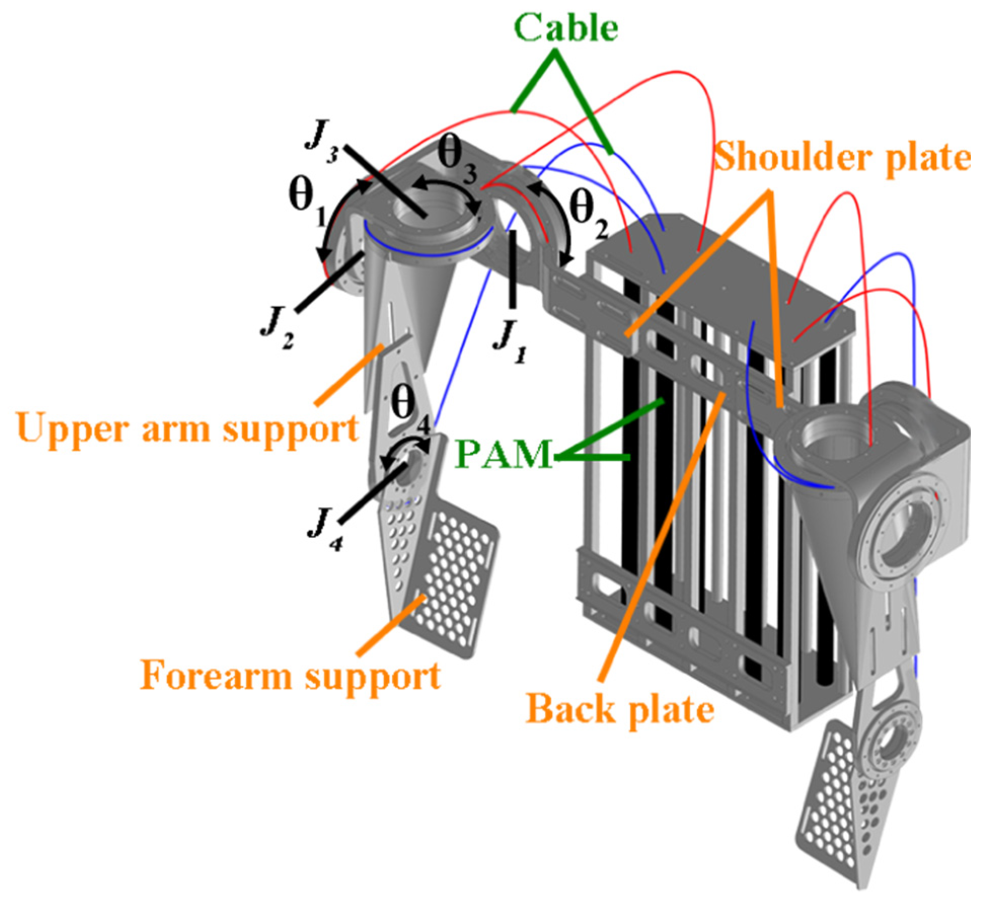
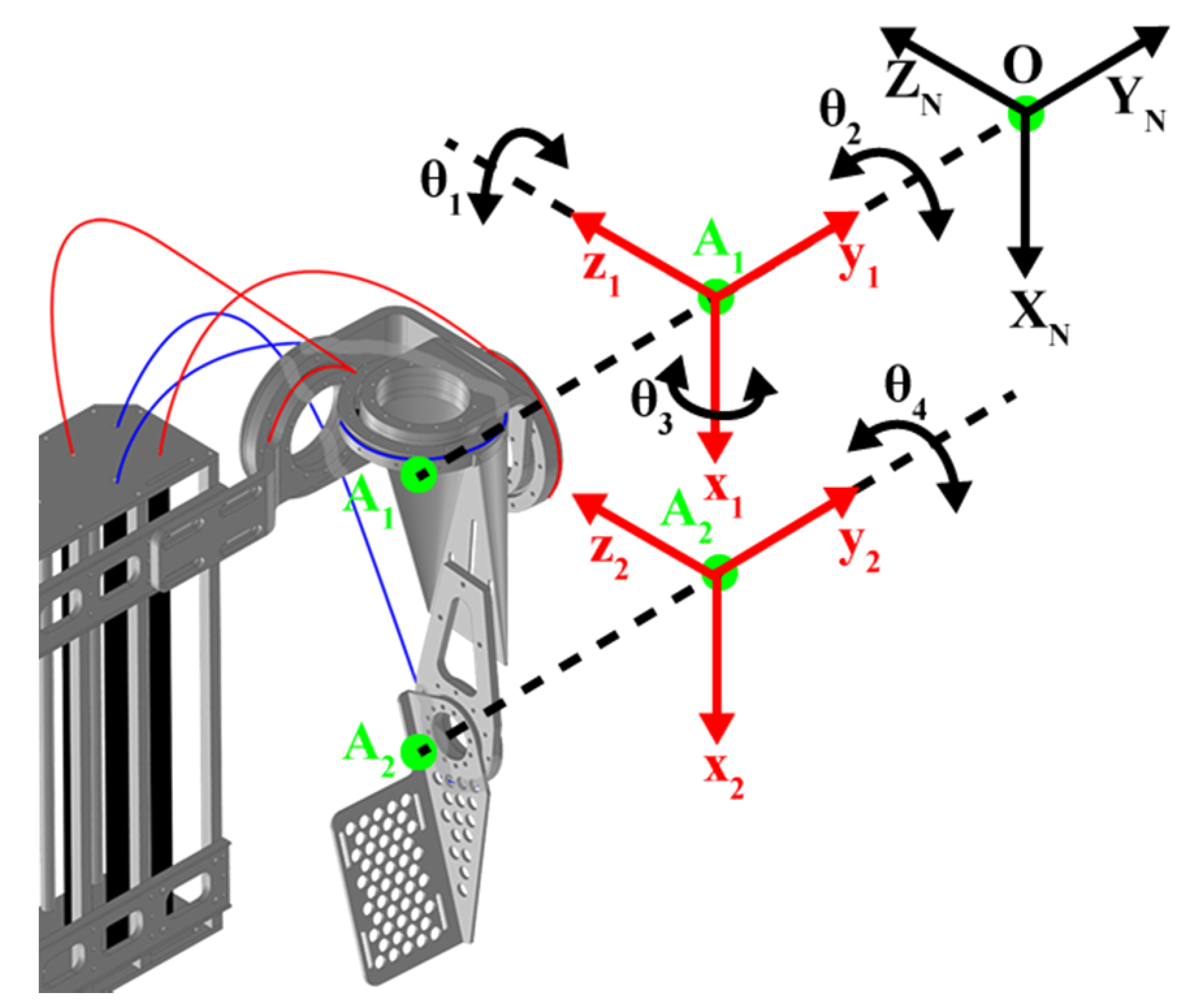
The design of an upper-limb exoskeleton robot must comply with the movement of a human arm and match with the anatomical structure as closely as possible. However, the detailed designs will result in a complex and bulky exoskeleton structure. As shown in Figure 1, the proposed upper-limb exoskeleton robot in this paper has four DOFs according to the required function, mainly including shoulder abduction/adduction θ_1 of the joint , shoulder flexion/extension θ_2 of the joint , shoulder internal/external rotation θ_3 of the joint , elbow flexion/extension θ_4 of the joint .
The shoulder joint of a human being is a ball-and-socket joint and kinematically similar to a serial chain with three revolute joints, whose axes intersect at a single point [23,24]. In this regard, the shoulder joint of the developed exoskeleton robot employs three perpendicular revolute joints as the ball-and-socket joint design. Each joint is made with a bearing embedded in the support aluminum plate through outer and inner ring axes and mounted with a high-resolution incremental encoder for the joint angle measurement. The cables are routed on the outer or inner ring axes at one end, and the other end is connected to the corresponding PMA. The PMA is made by Festo, whose type is MAS-20-300N fluid muscle with an initial length of 300 mm, an internal diameter of 200 mm, and 25% of the maximum contraction. A proportional pneumatic pressure regulator (Festo VPPM-6L-L-1-G18-0L10H-V1N) with the pressure range of 0 to 10 (bar) relative to the input voltage is used to supply and control the air into the PMA. Each PMA utilizes a proportional regulator. All the PMAs are fixed at the backplate upright.
An NI sbRIO-9632 is embedded to control the whole system. The sbRIO system consists of four parts: two kinds of modules, including reconfigurable IO modules (RIO) and FPGA modules, a real-time controller, and an Ethernet expansion chassis. The analog-to-digital (AD) and digital-to-analog (DA) conversions are enabled by the NI 9234 and NI 9263 modules that are installed in the cRIO 9072. The input signal on the four channels of the NI 9234 is buffered, conditioned, and sampled by a 24-bit Delta-Sigma ADC. The analog output is enabled by NI 9263 through four channels with the specification of ± 10 V, 16-bit, 100 kS/s. The control algorithms and measurements were developed mainly in the Labview system.
When the air is compressed into the PMAs, the PMAs contract to generate a unidirectional pulling force through the cables, and thus turn the support plates to drive a wearer’s upper limb to realize a rehabilitation exercise. When the air is released from the PMAs, the exoskeleton robot returns to its original configuration by taking advantage of the upper-limb self-weight that exerts torques on these joints, except at the shoulder internal/external rotation joint, in which a spring in a serial connection to the PMA is added to provide a restoring torque.
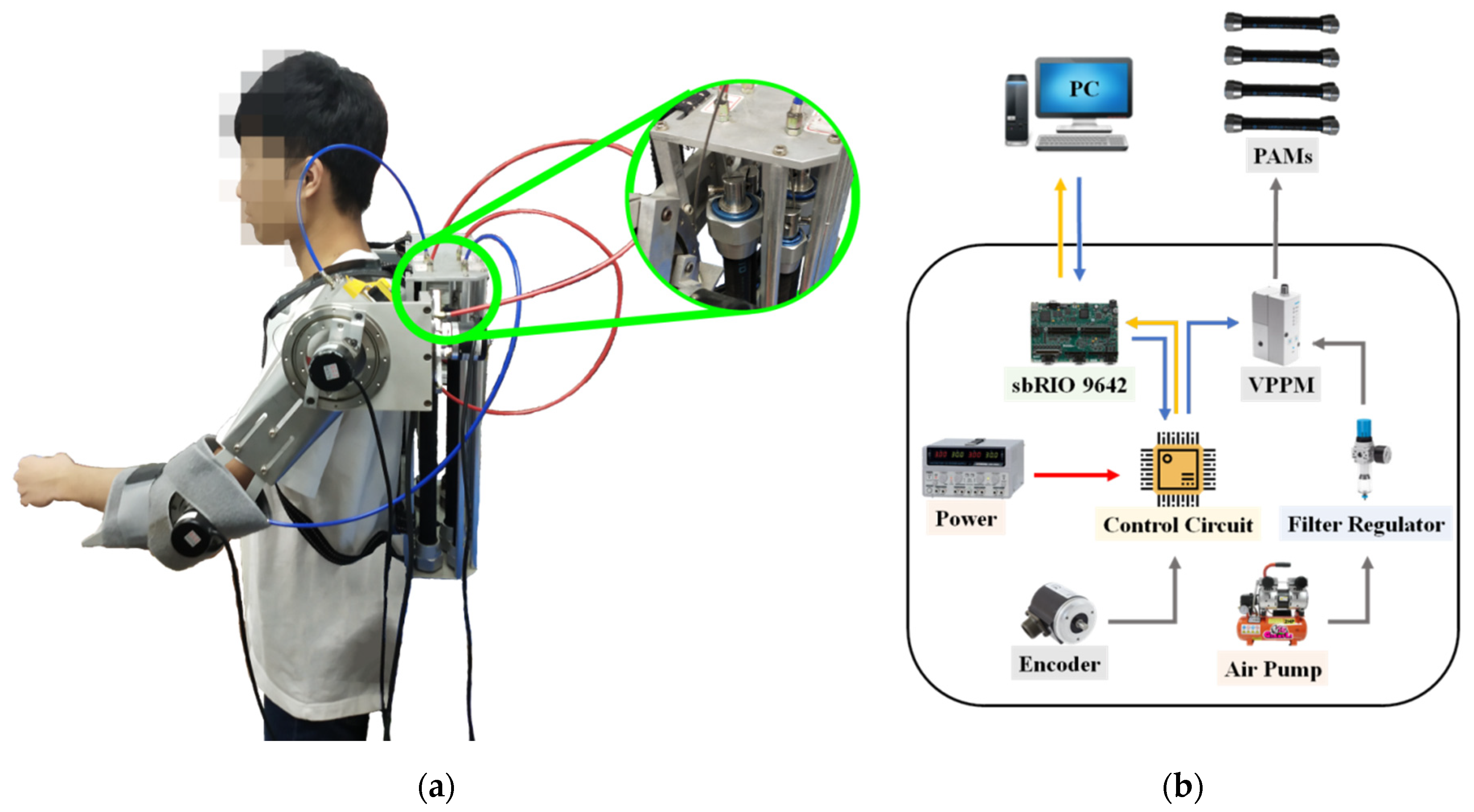
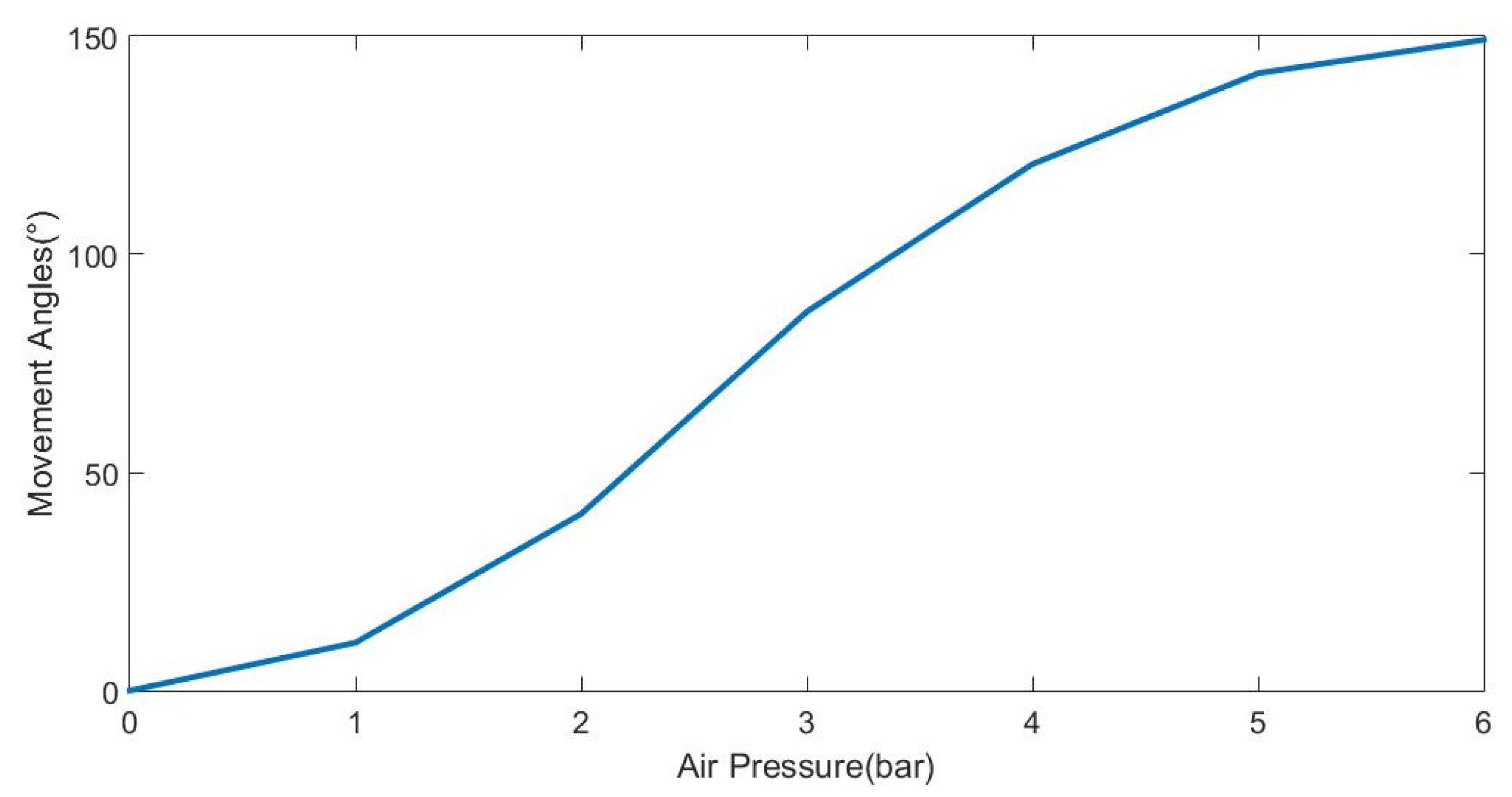
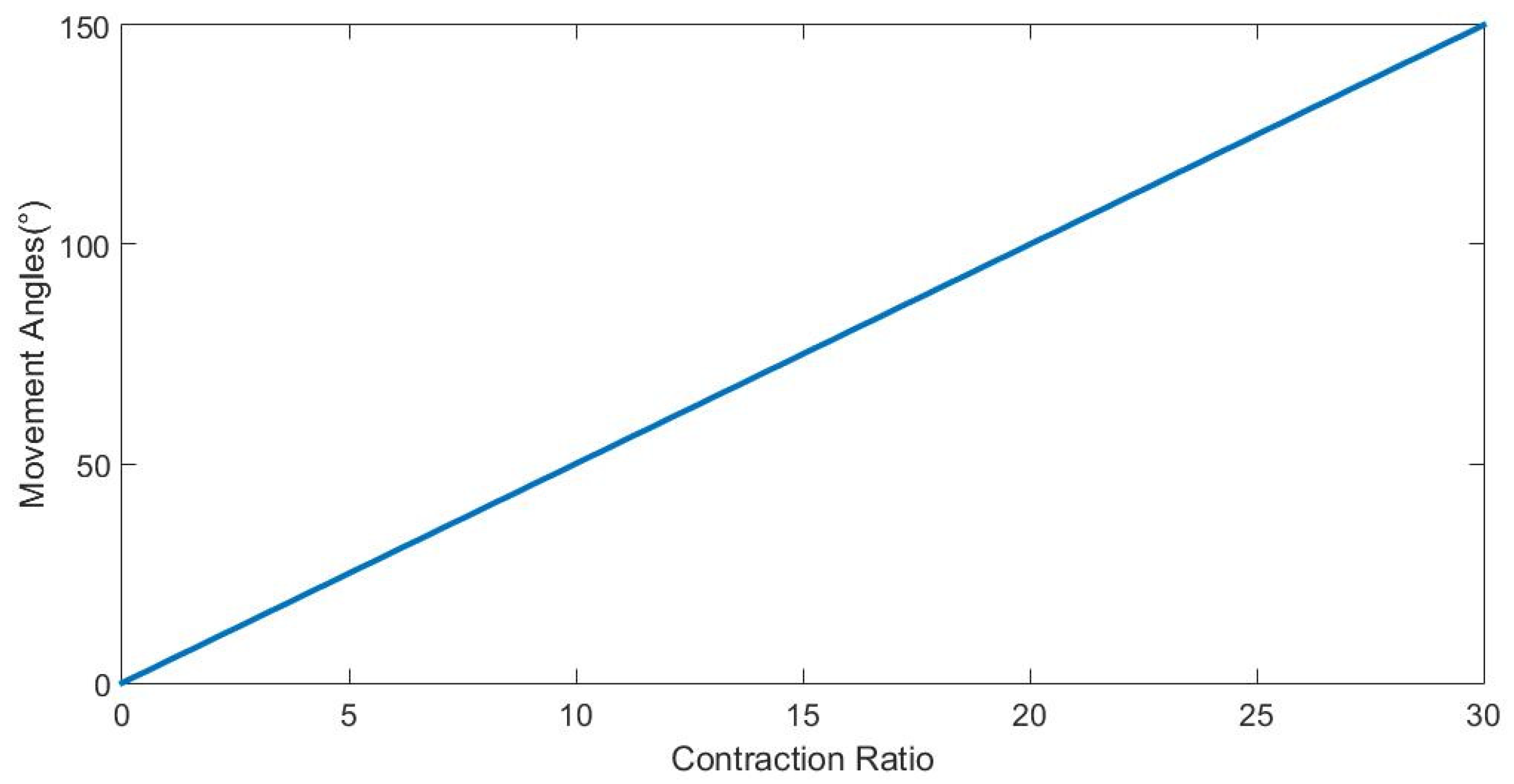
With single PMA for each joint, instead of one pair that imitates human antagonist muscles, the structure and control complexity of the developed upper-limb exoskeleton robot is reduced. The total weight stands at 5.6 kg, including the actuator system, making it low cost, lightweight, and portable, as shown in Figure 2a. Figure 2b is the associated control system. Based on the experimental testing, the moving angle as the function of air pressures is shown in Figure 3. Figure 4 presents the relation of the movement angles and the contraction ratios. The range of motion (ROM) of each joint is listed in Table 1. Although the ROMs of the currently proposed exoskeleton robot are less than a normal human, they can assist patients suffering from moving difficulty in one direction or high stiffness in upper limb flexor muscles to take frequent intensive rehabilitation exercises at home or in the community while taking into account safety. Our proposed upper-limb exoskeleton robot is light due to the use of PMAs and safe due to the limited range of motion at each joint. Therefore, the exoskeleton robot is portable, thus permitting operation at home or in the community if required.
3. Dynamic Equations
3.1. PMA Model
In our developed exoskeleton robot, PMAs are utilized as the force producers. The braided pneumatic actuator is composed of a non-expandable braided shell and an internal rubber tube. When air is compressed into the tube by a compressor, PMA contracts to generate a pulling force in the axial direction according to its inflation volume, actuating the corresponding joint through the cable. Based on the developed model in [25,26,27], the contractile force of PMA is a monotonic function of braid angle θ and the linearly proportional relative pressure P, and thus can be expressed as
where ε == Δl/, β =, α =, is the initial braid angle of the PMA, Δl is the contraction length that is the difference of initial length and the actual length of the PMA, and r0 is the initial radius of PMA. Moreover, the input voltage to the proportional pneumatic pressure regulator and the internal pressure of the PMA is in a linear relation; the relative pressure P can be replaced by the control input voltage for control.
3.2. Dynamics of the Exoskeleton Robot
Without loss of generality, considering the upper arm of the exoskeleton robot for a dynamic formulation as shown in Figure 5, an inertial coordinate system N-frame, {O_XNYNZN}, is defined with the origin O being at the intersection point of the three revolute joints of the shoulder. With the reference to the initial configuration, the ZN, YN, and XN axes are defined along the J1-, J2-, and J3-joint axis, respectively. Two local coordinate systems, l1-frame {A1_x1y1z1} and l2-frame {A2_x2y2z2} with their corresponding origins A1 and A2, are attached to the respective upper arm and forearm, in which A1 is coincident with the origin O, and A2 is located at the elbow J4-joint.
With the definitions of the coordinate systems, the absolute angular velocity of the limb, i (=1,2), is defined concerning the li-frame, and, thus, the kinetic energy T and the potential energy V of the exoskeleton robot including the wearer’s arm are formulated as
where mi is the mass of the limb i (=1,2), Li is the length vector, is the position of the center of mass of the limb i, is the unit vector along the i-th limb axis and is defined as , g denotes the gravity, Ii means the mass moment of inertia matrix of the Ai in the li-frame, and the tilde over a vector denotes a skew-symmetric matrix formed from this vector. Besides, describes the rotation matrix from the body-fixed li-frame to the inertial N-frame. Moreover, a spring potential energy is also considered in (3) due to spring with the coefficient k being attached to the joint J3.
Since the kinetic energy is expressed by the rotation matrices and the absolute angular velocities are with the respective local coordinate systems, the traditional Lagrangian formulation in generalized coordinates cannot be directly applied to dynamic modeling. Instead, following the Boltzmann–Hamel–d’Alembert formalism for modeling in [28,29], the closed dynamic equations for the upper-limb exoskeleton robot are formulated as
in which is the joint angle vector for the shoulder joints and elbow joint of the exoskeleton, the inertia matrix M is symmetric and positive definite, is the Coriolis and centrifugal vector, G is the gravity vector, and is the joint torques. All the matrices, vectors, and symbol definitions in (4) can be fully referred to in the Appendix A. It is seen that the formulated equations of motion in a matrix–vector form stay compact and closed, making a model-based control design appropriate. Moreover, some useful properties for controller design exist in these matrices; () is a skew-symmetric matrix, and thus for any vector x,
The joint torque on the i-th joint is computed by multiplying the contractile force Fi of the PMA i (i = 1, …4) by the corresponding joint radius ri. In the contractile force, the relative pressure Pi is linearly proportional to the applied voltage ui. The contraction length Δli of the PMA leads to the joint angle , and can be related with Δli = ri . The joint torque is thus expressed as
where . Note that the joint torques actuated by PMAs are nonlinear functions of joint angles. Moreover, in =, the contractile force Fi is defined as positive, the applied voltage ui to a PMA is larger than zero, and the corresponding joint radius ri is also positive, thus, the input function is positive.
Substituting Equation (6) into Equation (4), the dynamic equations are rewritten as
where the input matrix B = diag[f1 … f4] is a diagonal positive definite matrix. Furthermore, the dynamic equations of the exoskeleton robot are now represented with the input voltages. The controller will be designed for the input voltages.
4. Control Design
In performing effective rehabilitation training, the effects containing the uncertainties, external disturbances, nonlinearities, and the simplified dynamics model must be addressed for the motion controller design for better tracking performance. Therefore, a fuzzy sliding mode control (FSMC) is proposed for the rehabilitation control of the PMA-actuated upper-limb exoskeleton robot.
4.1. Sliding Mode Control
Due to simple control and easy implementation, the conventional sliding mode controller (SMC) is an effective methodology that has been successfully applied to many nonlinear systems, e.g., electromechanical plants [30], induction motors [31], parallel manipulators [32], auto-warehousing crane systems [33], and autonomous underwater vehicles [34]. Especially for the control of PMA, Tondu et al. [35] applied a second-order sliding mode control for a pneumatic artificial muscle-driven robot-arm. Its twisting algorithm directly drives joints without a chattering phenomenon. Van Damme et al. [36] presented a proxy-based sliding mode control to control a 2-DOF planar manipulator actuated by pleated pneumatic artificial muscles, and performance was experimentally evaluated. Lilly and Yang [37] applied the sliding mode technique to control the elbow motion of the arm with antagonistic pneumatic muscle actuator groups. The boundary layer concept was used to eliminate chattering. To remove the discontinuous signal of the SMC, different methodologies were employed in the mentioned references. In our work, the FSMC was used for the rehabilitation control of the upper-limb exoskeleton robot. The fuzzy type of reaching control not only can eliminate chattering but also can overcome system uncertainties. The desired closed-loop performance of the FSMC is first represented by a sliding surface that the SMC specifies. In a second-order system, a time-varying sliding surface is defined as
where is a symmetric positive definite matrix and linked to the desired performance of the closed-loop system; is the tracking errors in the joint angles.
If a reference joint rate is introduced by , the sliding surface can be interpreted as the tracking velocity error concerning the reference joint rate, and Equation (8) is expressed as
Indeed, Equation (9) may be interesting as a velocity error term. When at the reaching phase, a designed hitting control law compels the system trajectories onto the sliding surface. If the system state slides to the origin along a trajectory in a sliding mode, it remains on the sliding surface. Therefore, to complete the trajectory tracking, a sliding mode controller comprising the nominal control and the reaching control was designed for the rehabilitation control of the exoskeleton robot. Namely, the control input takes the form
If the system dynamics is completely known, the equivalent control is the control input vector that makes the derivative of a Lyapunov function V equal to 0. That is, a Lyapunov function is chosen as
then taking differential V,
If the control input is chosen as , would be zero. However, if the exoskeleton robot parameters were not completely known to us, the equivalent control would be defined as
in which , , and are the estimates of B, M, H, and G, and with , , and bounded. The diagonal control gain components of B with 0<<bi< are unknown but of known bounds. Therefore, the estimated of gain bi can be naturally chosen as 0<<<, which is the geometric mean of the above bounds.
The reaching control in (10) can be conventionally expressed as
in which is defined as the switching gain vector of components , which is related to the upper bound of uncertainties, and sign[.] is the sign function. The reaching control mainly accounts for system uncertainties or external disturbances.
4.2. Fuzzy Sliding Mode Control Design
The uncertain values of s and the associated discontinuous reaching control always generate chattering phenomena. To eliminate the jitter problem, a fuzzy sliding mode controller (FSMC) [38] is used instead of the SMC, and thus, the reaching control with a fuzzy type is represented as
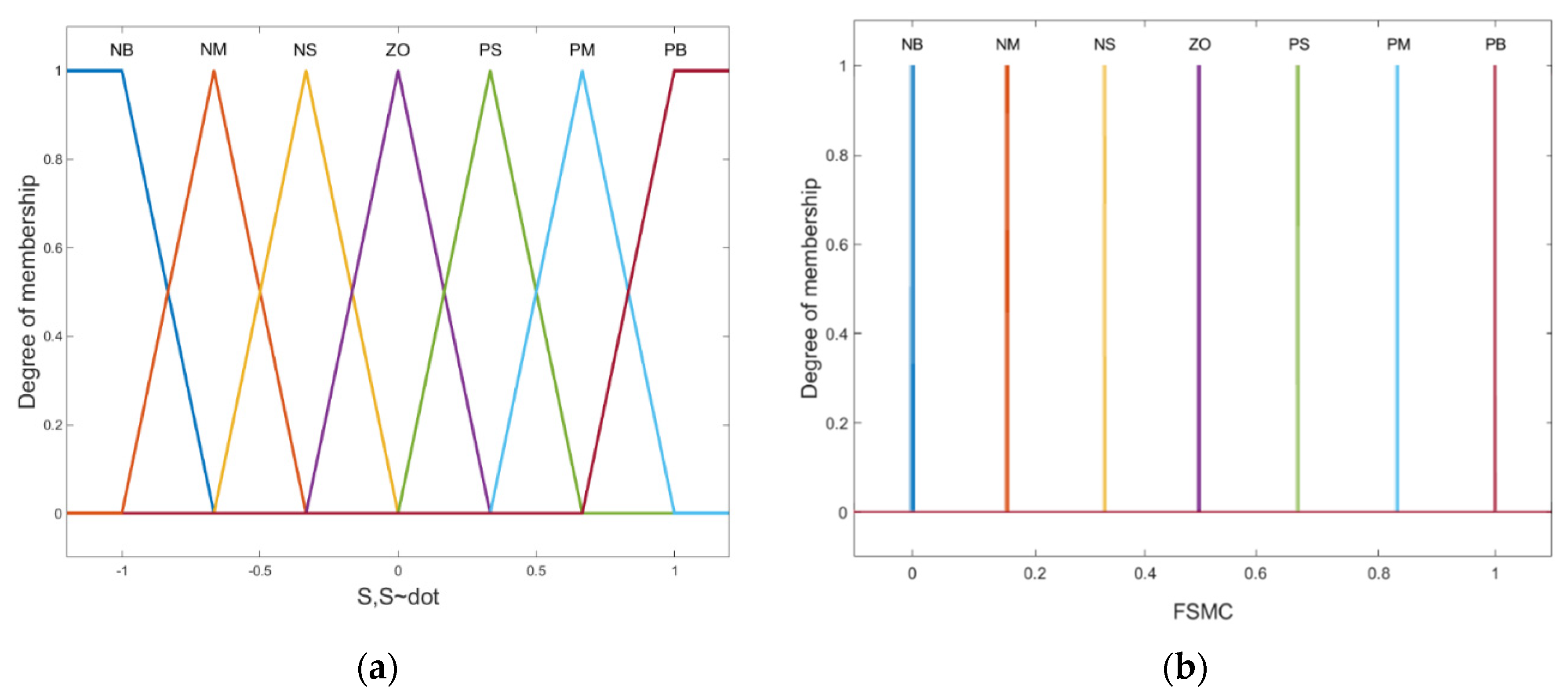
is defined as the fuzzy gain vector of components . The fuzzy function FSMC maps two linguistic input variables, s(t), and (t), to the linguistic output based on the Mamdani inferred rules. The fuzzy rules are shown in Table 2, in which there are seven fuzzy rules: NB (Negative Big), NM (Negative Medium), NS (Negative Small), Z (Zero), PS (Positive Small), PM (Positive Medium), and PB (Positive Big). The input–output relationships are determined based on a fuzzy logic IF-THEN rule basis, which is typically used in the fuzzy inference system and is expressed as :: IF is and is THEN is , i = 1,…,n. in which and are the input fuzzy sets; is the output fuzzy set.
The membership functions of input and output linguistic variables are chosen as in Figure 6. The product inference with singleton fuzzification and centroid defuzzification methods has been utilized for fuzzy implications. In the scheme as proposed in [39], the normalized fuzzy function has been set as ()(.
4.3. Stability Analysis
The equivalent control (13) and the reaching control (15) are combined to (10) to control the upper-limb exoskeleton robot with the dynamics Equation (7). A Lyapunov function is chosen as Equation (11), and, thus, the robust trajectory control for rehabilitation tasks is further proved by the Lyapunov stability analysis.
Differentiating (11),
in which , , , and that is defined as the i-th diagonal component of . Furthermore, if (16) is expressed in indexing, it becomes
If choosing , letting the reaching control gains be with << always allows satisfying the reaching condition . Thus, it can be guaranteed that the system reaches the surface s = 0 in a finite time. The trajectories remain on the surface once, and, therefore, the desired trajectories are obtained. This completes the stability proof and guarantees the asymptotic stability of the closed-loop system.
Although mainly depends on the equivalent errors , , , we can estimate the bounds of these equivalent errors so that is also bounded. By letting and be substituted into the reaching control , the controller u(t) =+ for the rehabilitation, and control is thus implementable.
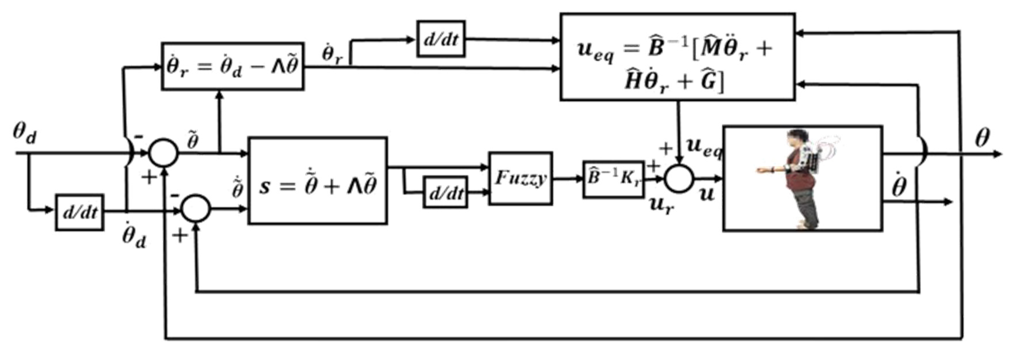
The configuration of the FSMC structure for the PMA-actuated upper-limb exoskeleton robot is shown in Figure 7. The desired joint angles imply a rehabilitation trajectory. The control signals u for the PMAs are synthesized based on the aforementioned FSMC design, and, thus, the PMAs produce the corresponding actuating forces to drive the exoskeleton robot to track the rehabilitation trajectory.
5. Realization and Discussion
Experiments were conducted to simulate a rehabilitation exercise, executing the robot assistance rehabilitation based on the proposed PMA-actuated upper-limb exoskeleton robot with the designed control architecture. The system parameters including the wear’s upper arm and forearm are measured or estimated by the CAD model with = 1.26 kg, = 0.63 kg, = 0.1134 kg·, = 0.0252 kg·, = 0.3 m, and = 0.2 m. The joint radii are = 0.06 m, = 0.06 m, = 0.06 m, and = 0.03 m. The PMAs in use are = 2 cm, = 30 cm, = 25°, α = 480, β = 17.58. The spring coefficient is k = 2.2 N/m. The reaching control gain matrix is chosen as = diag (0.8, 0.6, 0.2, 0.5).
5.1. Rehabilitation Trajectory Planning
Based on a rehabilitation process in a free-hand manner, one held the end-effector to drive the exoskeleton robot according to the rehabilitation motions of the upper limbs. The joint angles at each joint were then measured and recorded by the encoders. However, the recoded data are not smooth due to the unconscious tremor of hands. Moreover, other external disturbances also deteriorate the continuity of the rehabilitation trajectories, reducing the execution performance.
Conventionally, curve fitting is usually utilized to smooth a set of discrete points. Many methods can be applied to the curve fitting; in this paper, the Fourier series method was used to smooth and generate the desired rehabilitation trajectories because the Fourier series have the cycle propriety that satisfies the repeatability and consistency during the rehabilitation process. The Fourier series is expressed as
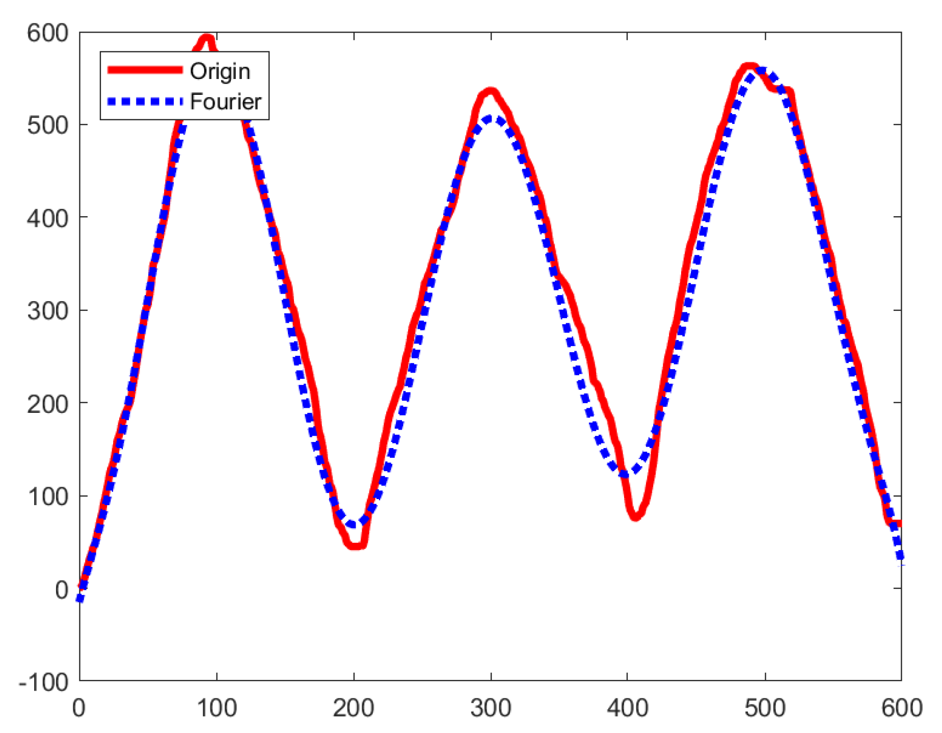
where the Fourier coefficients , , , …, , along with the rehabilitation trajectory frequency are solved by the optimization algorithms based on recorded raw data. Figure 8 shows the curve fitting trajectory in the Fourier series based on the original raw data. It is seen that the modified trajectory is more smooth and can be appropriate for the rehabilitation trajectory.
5.2. Realization on Shoulder Joints J1, J2 and Elbow Joint J4 Rehabilitation
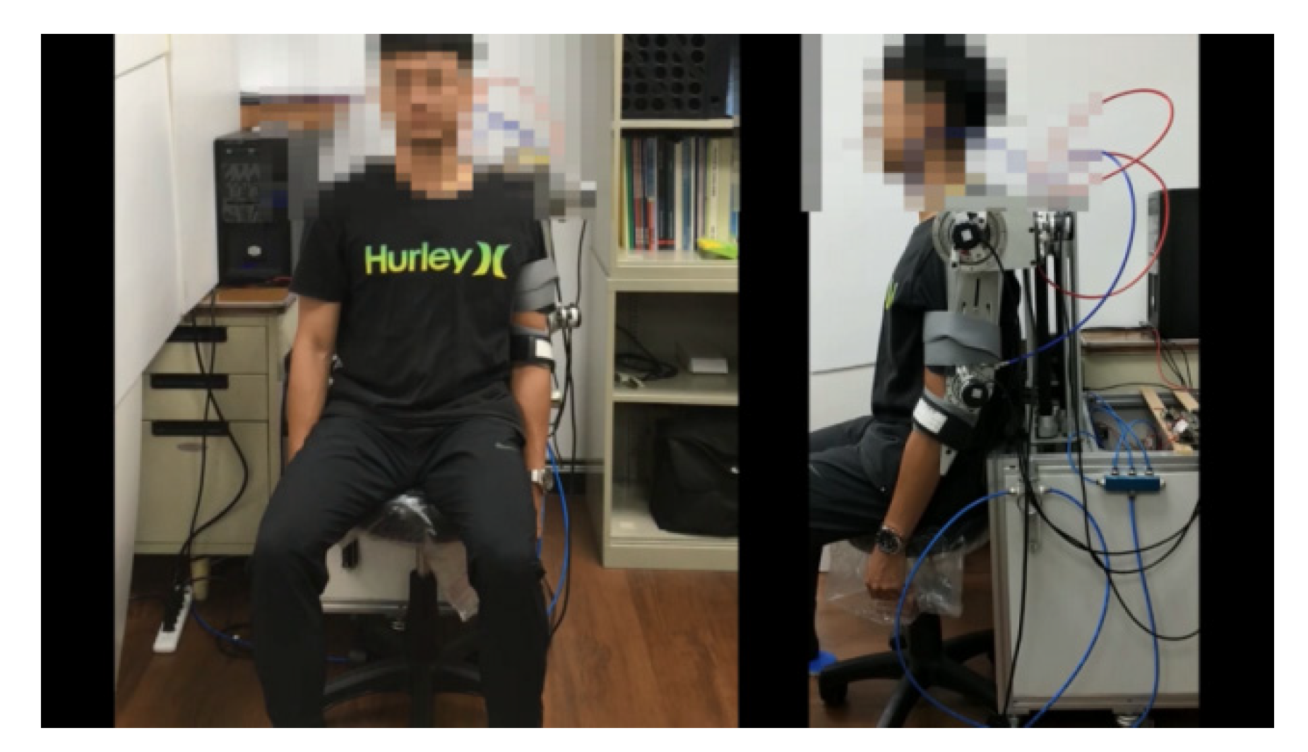
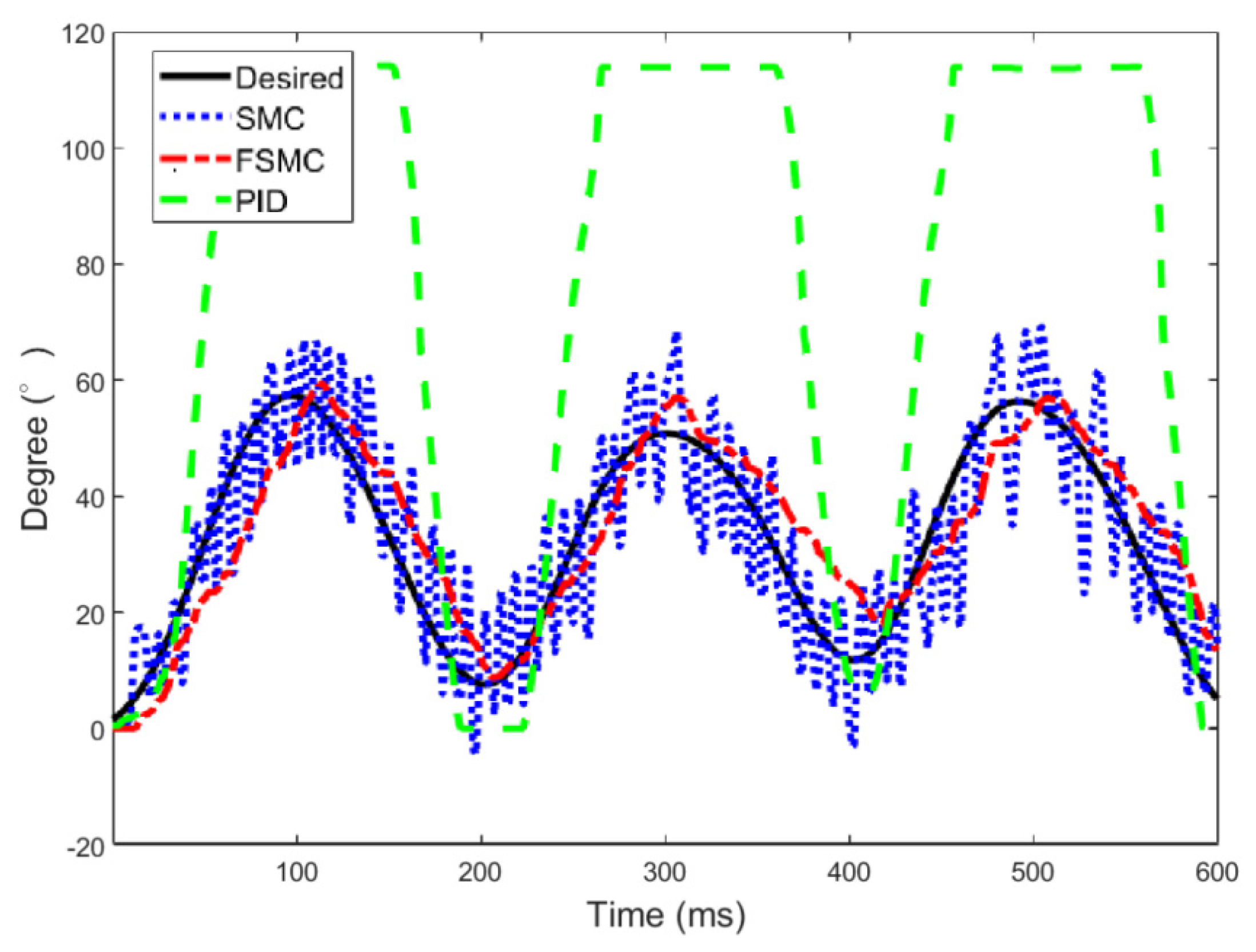
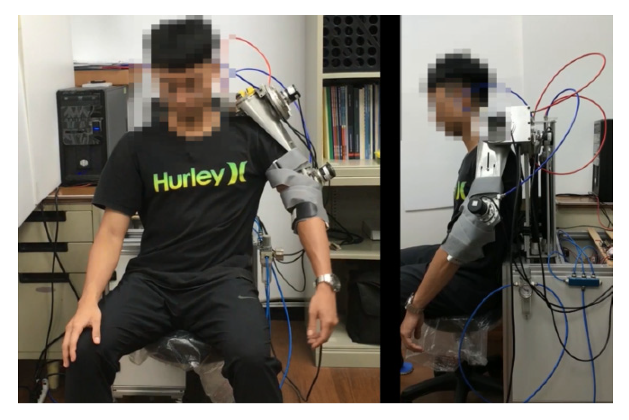
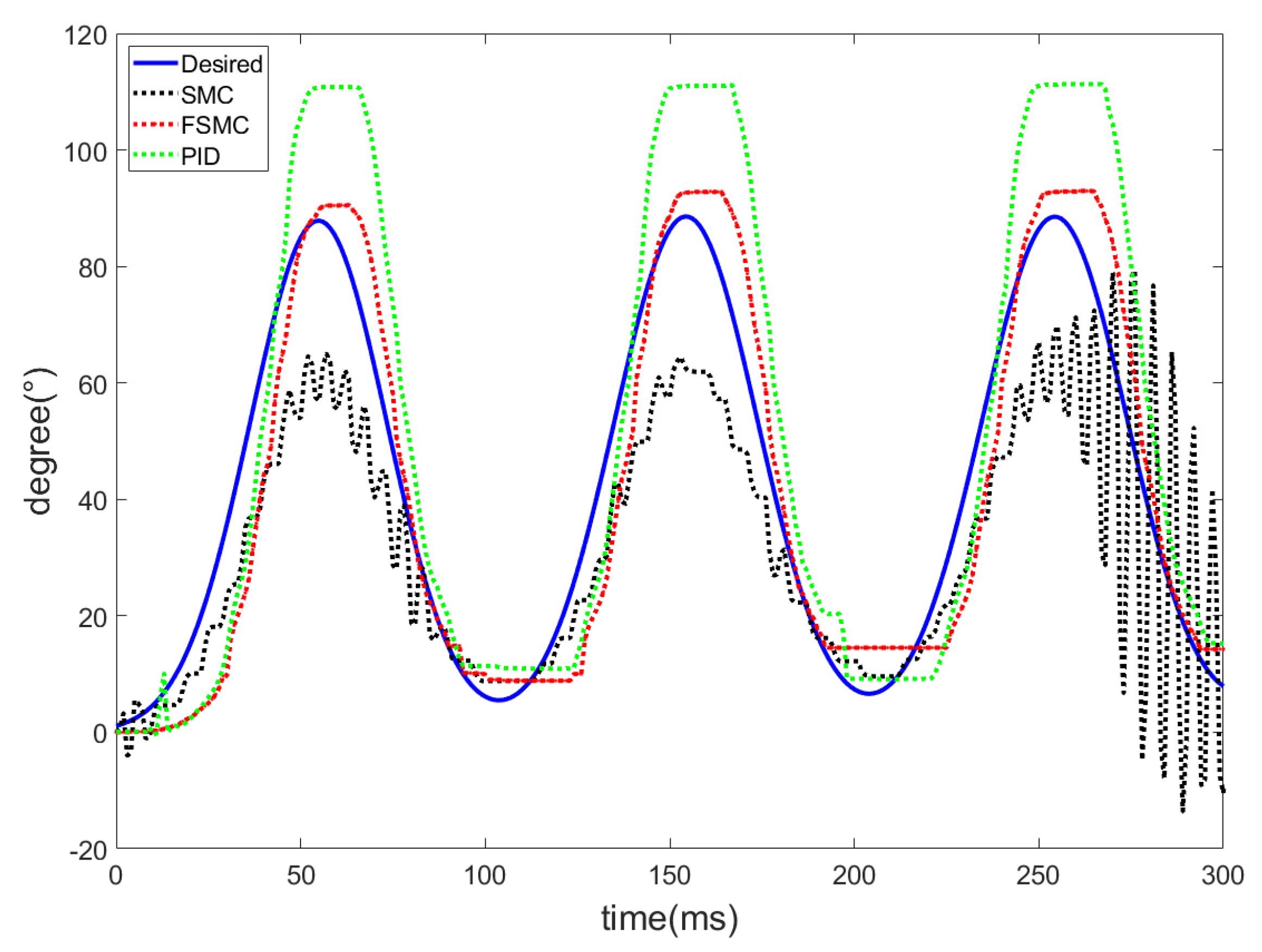
As shown in Figure 9, a subject wore the exoskeleton robot with his arms initially hanging down. The rehabilitation trajectory was specified with shoulder internal/external rotation = 0, which is a very common trajectory on rehabilitation exercises. The frequencies were determined as = 0.009398, = 0.00966, = 0.009336 for the corresponding desired joint trajectories. Three controllers, PID, sliding mode control (SMC), and fuzzy sliding mode control (FSMC) were conducted and compared. The tuning process for the PID control is based on the Ziegler–Nichols method. Kp is increased (from zero) until it reaches the ultimate gain, at which the output of the control loop has stable and consistent oscillations, and then to obtain Ki and Kd.
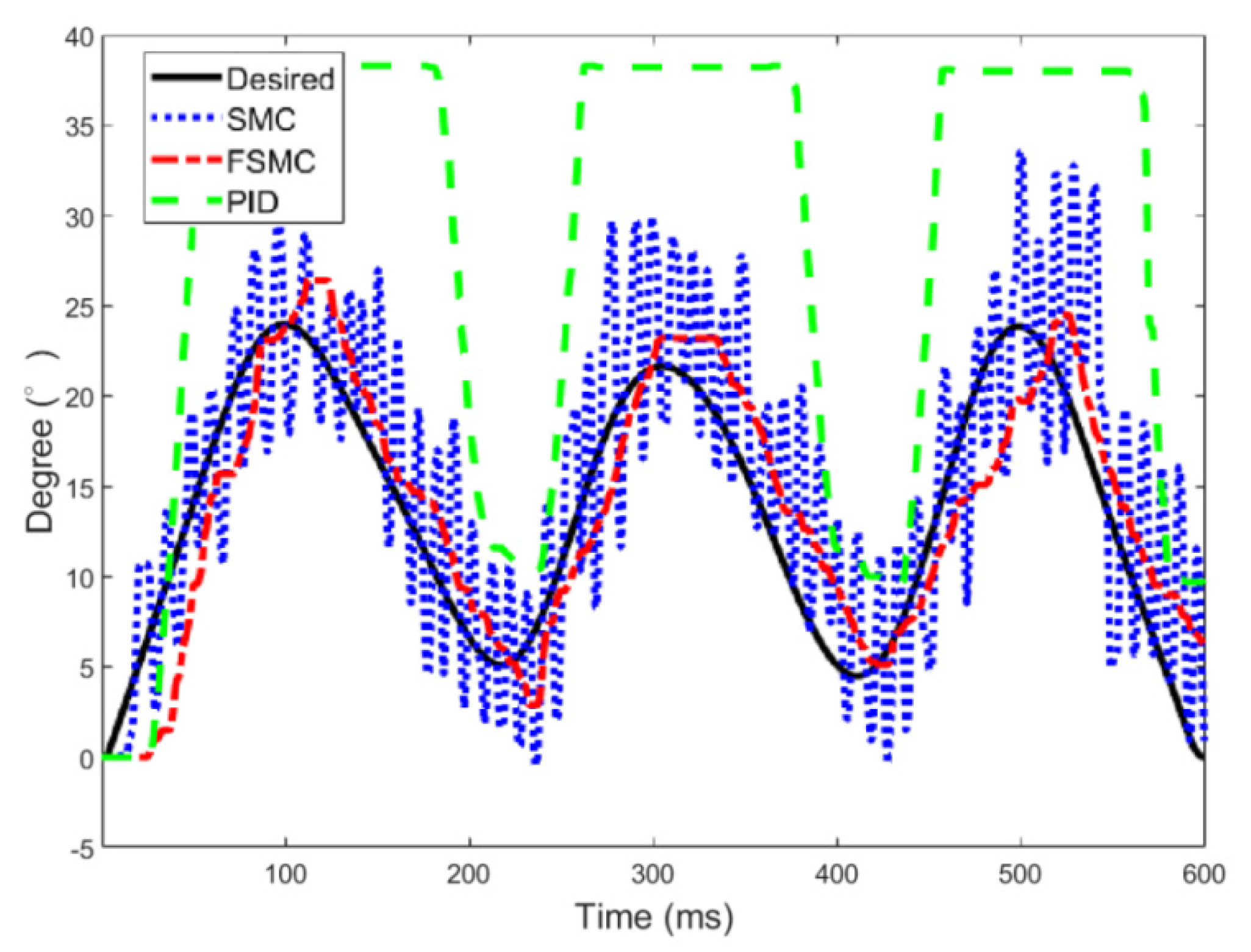
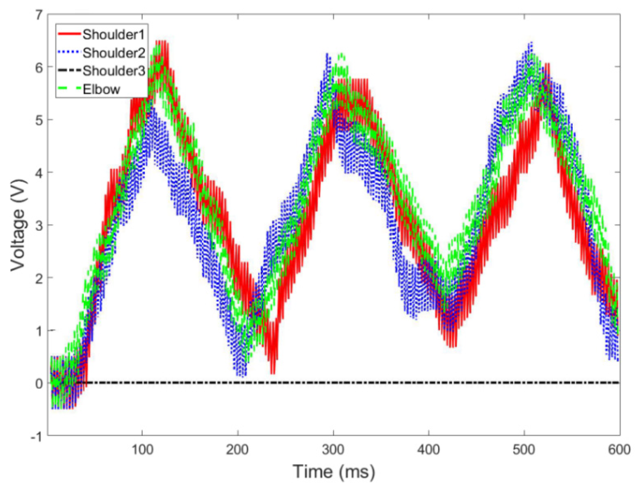
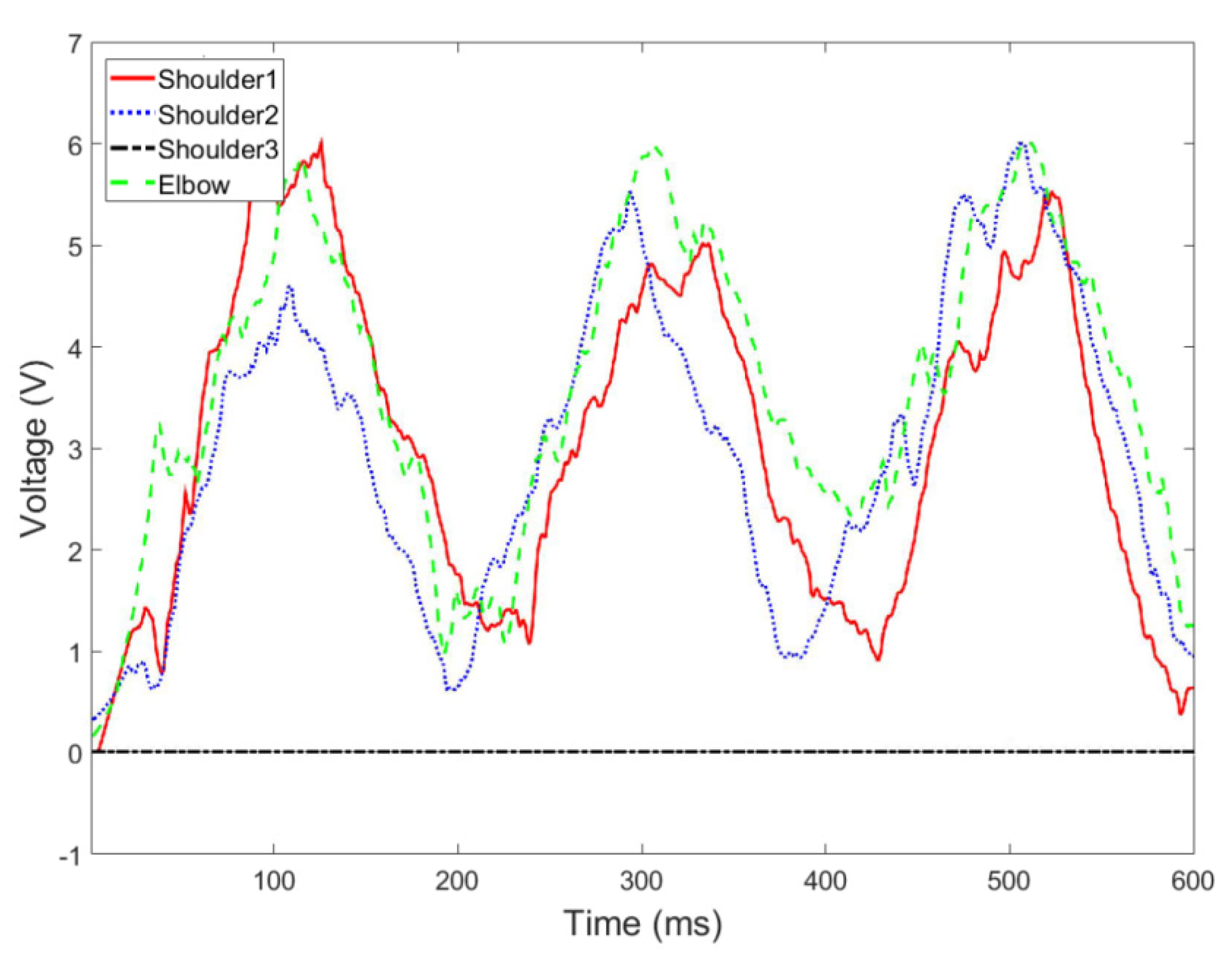
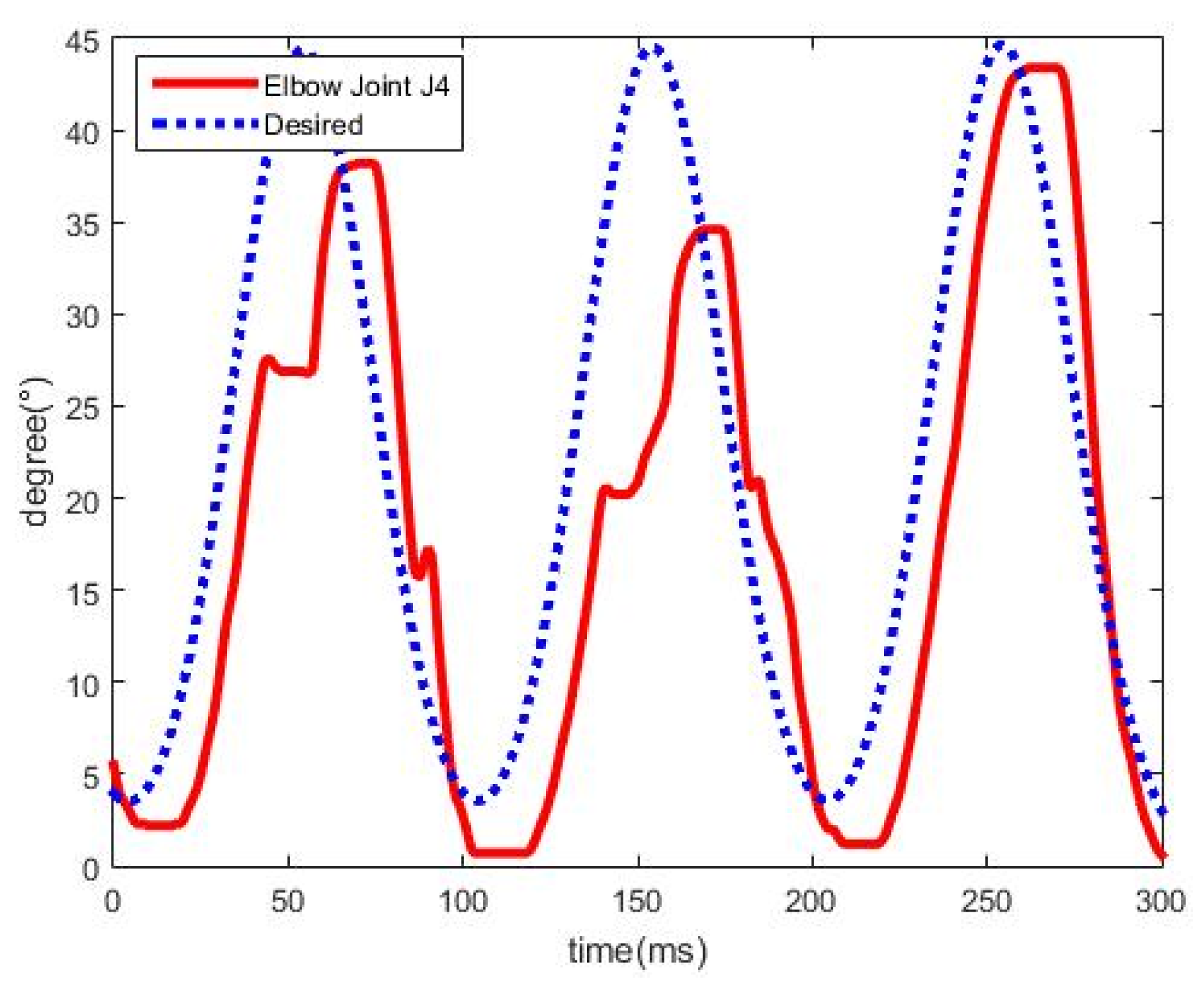
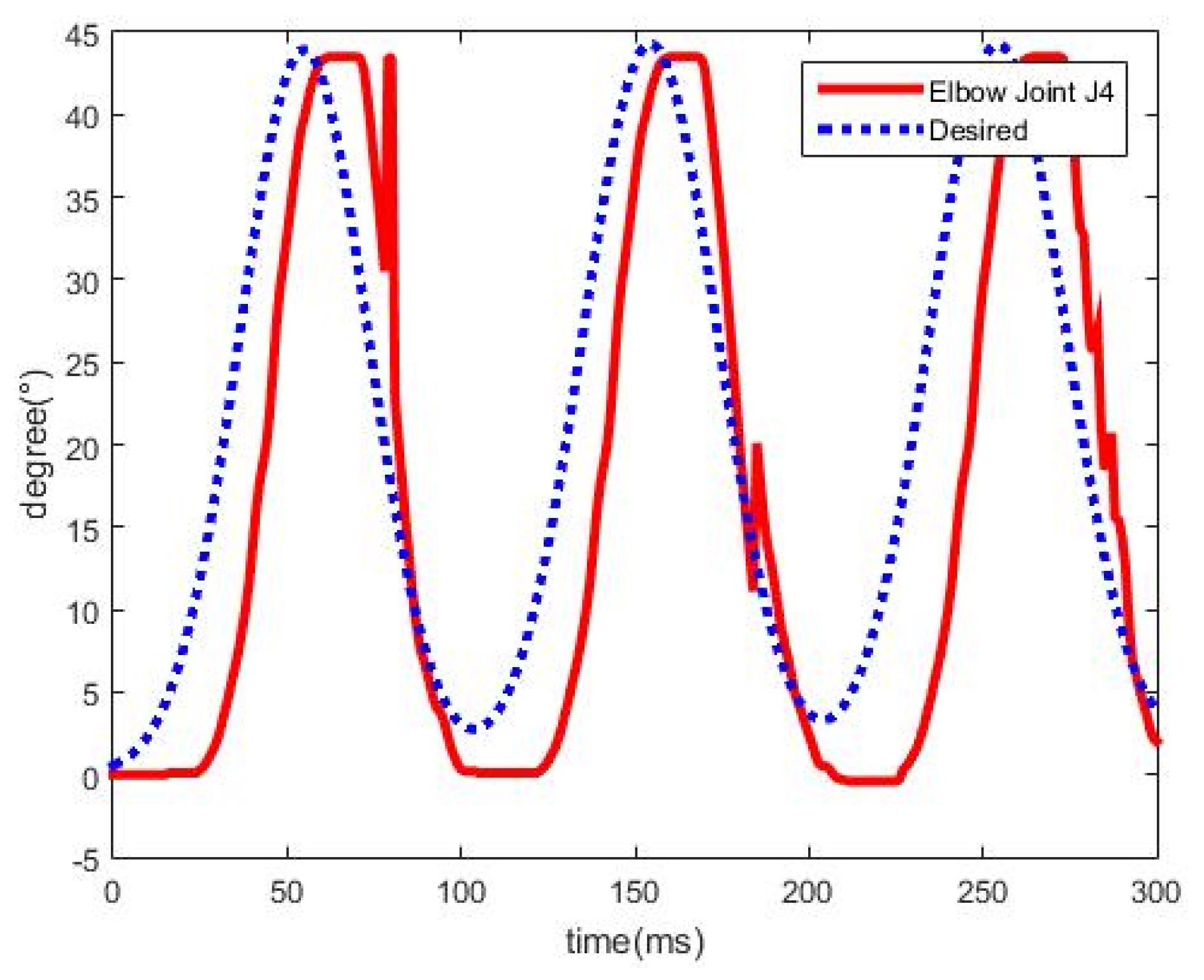
As shown in Figure 10, the PMA-actuated upper-limb exoskeleton robot drove the arm according to the planned trajectory. The trajectories of the joints , , and for the three controllers are separately presented in Figure 11, Figure 12 and Figure 13. The results show that the PID control is very hard to track the planned trajectories because of the compressibility of air and nonlinear effects and uncertainties of the robot system. Besides, when the air pressure significantly varies, the PID control will cause a violent response. Moreover, the PMA contraction rate cannot respond very fast to errors, and, thus, a control performance is saturated. The SMC can overcome uncertain disturbances to follow the rehabilitation trajectories, but accompanying chattering may lead to harm to subjects, thus, it is clear that the proposed FSMC has superior tracking performance to the other two controllers for the PMA-actuated exoskeleton robot on the rehabilitation applications.
5.3. Rehabilitation for Shoulder Internal/External Rotation
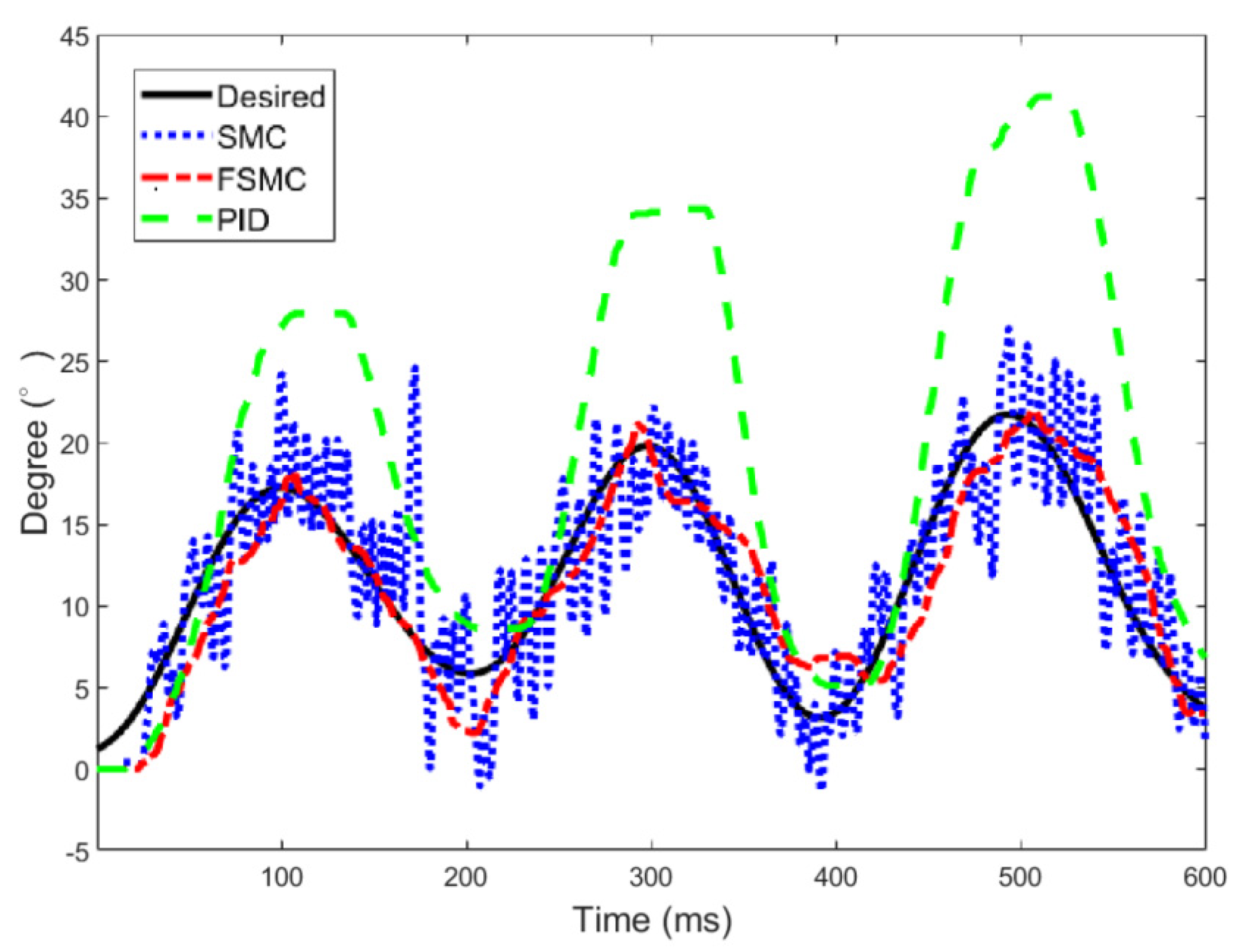
In this rehabilitation maneuver as shown in Figure 16, the shoulder internal/external rotation with a frequency of = 0.004682 was realized at the fixed joint angles , , . The trajectories for the shoulder internal/external rotation are displayed in Figure 17. The FSMC has better tracking performance for the rehabilitation exercises. Notably, the chattering increases largely after the third rehabilitation cycle for the SMC and thus results in unpredicted rehabilitation disturbance.
The RMS errors for the three controllers, PID, SMC, and FSMC, in the rehabilitation maneuvers are presented in Table 3. The FSMC has a better tracking performance in our designed PMA-actuated exoskeleton robot.
5.4. Rehabilitation while Suffering from Instant Spasm and Tremor
Sometimes spasm and tremors may occur during a rehabilitation process [40]. These phenomena must be detected to ensure the wear’s safety. Spasm is classified as the instant type and sustaining type. For the sustaining spasm, the training process must be halted by releasing the pressure inside the PMAs. However, the instant type of spasm vanishes soon after it happens. In this section, a flexion/extension exercise on the elbow joint was implemented with instant spasm and tremor occurring during the rehabilitation process.
Figure 18 displays the trajectories of elbow joint using the proposed FSMC with an instant spasm occurring. From the results, the instant spasm temporarily leads to larger tracking errors, however, as the instant spasm vanishes, the rehabilitation process can continue with a stable trajectory tracking.
For the tremor occurring in the rehabilitation exercise, the trajectories of elbow joint are as shown in Figure 19. It is found that the proposed FSMC is robust to the tremor while carrying out rehabilitation exercises.
6. Conclusions
This paper concludes with the following main contributions: a new 4-DOF PMA-actuated upper-limb exoskeleton robot for rehabilitation training was developed. The controller, FSMC, taking advantage of the robustness of the SMC and chattering elimination of FC, was designed for the control of the exoskeleton robot. Based on the realization of rehabilitation exercise, the tracking performance of the FSMC is observed in comparison to that of the PID and SMC. The executed rehabilitation maneuvers, especially with instant spasm and tremor happening, validate the availability and robustness of the designed PMA-actuated exoskeleton robot on the rehabilitation exercises. More noticeably, due to the portable and lightweight characteristics, the rehabilitation may be executed in the community by the proposed exoskeleton robot system.
In the future, the robot architectures will be further improved, e.g., the antagonistic PMAs used at joints to increase the ROMs of arms.
Author Contributions
Conceptualization: C.-T.C. (Chun-Ta Chen); Investigation: C.-T.C. (Chun-Ting Chen), W.-Y.L. and Y.-C.W.; Methodology: C.-T.C. (Chun-Ta Chen), W.-Y.L., C.-T.C. (Chun-Ting Chen) and Y.-C.W.; Software: W.-Y.L. and Y.-C.W.; Supervision: C.-T.C. (Chun-Ta Chen); Validation: C.-T.C. (Chun-Ta Chen), W.-Y.L. and Y.-C.W.; Writing—original draft: C.-T.C. (Chun-Ta Chen) and Y.-C.W.; Writing—review & editing: C.-T.C. (Chun-Ta Chen) and Y.-C.W. All authors have read and agreed to the published version of the manuscript.
Funding
This research was funded by the Ministry of Science and Technology of Taiwan grant number MOST 107-2221-E-003-025, MOST 108-2221-E-003 -024 -MY3 and MOST 108-2321-B-027-001.
Conflicts of Interest
The authors declare no conflict of interest.
Appendix A
Dynamic equations of the exoskeleton robot
where
,
,
,
In (A1), is the velocity transformation matrix between the absolute quasi-velocity and derivative of the Euler angles in the l1-frame{A1_x1y1z1}, being defined as
is the coordinate transformation matrix from the i-frame to the j-frame. Here the Z-Y-X Euler angles are used to specify the orientations of these two coordinates and are represented as
defines the unit vector along the y-axis of the l2-frame {A2_x2y2z2}.
In the inertia matrix, Coriolis, the centrifugal term, and the gravity vector,
in which Si (i = 1,2) is the unit vectors, respectively, along the upper arm axis (i = 1) and the forearm axis (i = 2); defines the unit vector along the z-axis of the l1-frame.
References
- Gopuraa, R.A.R.C.; Bandara, D.S.V.; Kiguchi, K.; Mannc, G.K.I. Developments in hardware systems of active upper-limb exoskeleton robots: A review. Robot. Auton. Syst. 2016, 75, 203–220. [Google Scholar] [CrossRef]
- Maciejasz, P.; Eschweiler, J.; Gerlach-Hahn, K.; Jansen-Troy, A.; Leonhardt, S. A survey on robotic devices for upper limb rehabilitation. J. NeuroEng. Rehabil. 2014, 11, 1–29. [Google Scholar] [CrossRef] [PubMed] [Green Version]
- Bogue, R. Exoskeletons and robotic prosthetics: A review of recent developments. Ind. Robot. 2009, 36, 421–427. [Google Scholar] [CrossRef]
- Cui, X.; Chen, W.; Jin, X.; Agrawal, S.K. Design of a 7-DOF cable-driven arm exoskeleton (CAREX-7) and a controller for dexterous motion training or assistance. IEEE-ASME Trans. Mechatron. 2017, 22, 161–172. [Google Scholar] [CrossRef]
- Tu, X.; Han, H.; Huang, J.; Li, J.; Su, C.; Jiang, X.; He, J. Upper limb rehabilitation robot powered by PAMs cooperates with FES arrays to realize reach-to-grasp trainings. J. Healthc. Eng. 2017, 2017, 1–15. [Google Scholar] [CrossRef] [PubMed]
- Anama, K.; Al-Jumaily, A.A. Active exoskeleton control systems: State of the art. Procedia Eng. 2012, 41, 988–994. [Google Scholar] [CrossRef] [Green Version]
- Kang, H.B.; Wang, J.H. Adaptive control of 5 DOF upper-limb exoskeleton robot with improved safety. ISA Trans. 2013, 52, 844–852. [Google Scholar] [CrossRef]
- Brahmi, B.; Saad Rahman, M.H.; Ochoa-Luna, C. Cartesian trajectory tracking of a 7-DOF exoskeleton robot based on human inverse kinematics. IEEE Trans. Cybern. 2019, 49, 600–611. [Google Scholar] [CrossRef]
- Wu, Q.; Wang, X.; Chen, B.; Wu, H. Development of an RBFN-based neural-fuzzy adaptive control strategy for an upper limb rehabilitation exoskeleton. Mechatronics 2018, 53, 85–94. [Google Scholar] [CrossRef]
- Galiana, I.; Hammond, F.L.; Howe, R.D.; Popovic, M.B. Wearable soft robotic device for poststroke shoulder rehabilitation: Identifying misalignments. In Proceedings of the 2012 IEEE/RSJ International Conference on Intelligent Robots and Systems, Vilamoura, Portugal, 7–12 October 2012; pp. 317–322. [Google Scholar]
- Zhu, X.C.; Tao, G.L.; Yao, B.; Cao, J. Adaptive robust posture control of parallel manipulator driven by pneumatic artificial muscles with redundancy. IEEE/ASME Trans. Mechatron. 2008, 13, 441–450. [Google Scholar]
- Tondu, B. Modelling of the McKibben artificial muscle: A review. J. Intell. Mater. Syst. Struct. 2012, 23, 225–253. [Google Scholar] [CrossRef]
- Kousidou, S.; Tsagarakis, N.; Caldwell, D.G.; Smith, C. Assistive Exoskeleton for Task Based Physiotherapy in 3-Dimensional Space. In Proceedings of the First IEEE/RAS-EMBS International Conference on Biomedical Robotics and Biomechatronics, Pisa, Italy, 20–22 February 2006; pp. 266–271. [Google Scholar]
- Tsagarakis, N.G.; Caldwell, D.G. Development and Control of a ‘Soft-Actuated’ Exoskeleton for Use in Physiotherapy and Training. Auton. Robots 2003, 15, 21–33. [Google Scholar] [CrossRef]
- Xiong, C.; Jiang, X. Control methods for exoskeleton rehabilitation robot driven with pneumatic muscles. Ind. Robot. 2009, 36, 210–220. [Google Scholar] [CrossRef]
- Andrikopoulos, G.; Nikolakopoulos, G.; Manesis, S. Design and development of an exoskeletal wrist prototype via pneumatic artificial muscles. Meccanica 2015, 50, 2709–2730. [Google Scholar] [CrossRef]
- Tu, X.; Zhou, X.; Li, J.; Su, C.; Sun, X.; Han, H.; Jiang, X.; He, J. Iterative learning control applied to a hybrid rehabilitation exoskeleton system powered by PAM and FES. Cluster Comput. 2017, 20, 2855–2868. [Google Scholar] [CrossRef]
- Oguntosin, V.; Harwin, W.S.; Kawamura, S.; Nasuto, S.J.; Hayashi, Y. Development of a wearable assistive soft robotic device for elbow rehabilitation. In Proceedings of the 2015 IEEE International Conference on Rehabilitation Robotics (ICORR), Singapore, 11–14 August 2015; pp. 747–752. [Google Scholar]
- Natividad, R.F.; Yeow, C.H. Development of a soft robotic shoulder assistive device for shoulder abduction. In Proceedings of the 2016 6th IEEE International Conference on Biomedical Robotics and Biomechatronics (BioRob), UTown, Singapore, 26–29 June 2016; pp. 989–993. [Google Scholar]
- Ohta, P.; Valle, L.; King, J.; Low, K.; Yi, J.; Atkeson, C.G.; Park, Y.L. Design of a lightweight soft robotic arm using pneumatic artificial muscles and inflatable sleeves. Soft Robot. 2018, 5, 204–215. [Google Scholar] [CrossRef] [Green Version]
- Wu, Y.C.; Chen, F.W.; Liao, T.T.; Chen, C.T. Force reflection in a pneumatic artificial muscle actuated haptic system. Mechatronics 2019, 61, 37–48. [Google Scholar] [CrossRef]
- Chen, C.T.; Wu, Y.C.; Chen, F.W.; Chen, M.Y. Pneumatic artificial muscle-driven control loading system (iFUZZY2017). Int. J. Fuzzy Syst. 2018, 20, 1779–1789. [Google Scholar] [CrossRef]
- Kim, B.; Deshpande, A.D. An upper-body rehabilitation exoskeleton harmony with an anatomical shoulder mechanism: Design, modeling, control, and performance evaluation. Int. J. Robot. Res. 2017, 36, 414–435. [Google Scholar] [CrossRef]
- Adams, J.A. Human Factors Engineering; Macmillan Publishing Co, Inc.: New York, NY, USA, 1989. [Google Scholar]
- Lin, C.J.; Lin, C.R.; Yu, S.K.; Chen, C.T. Hysteresis modeling and tracking control for a dual pneumatic artificial muscle system using Prandtl–Ishlinskii model. Mechatronics 2015, 28, 35–45. [Google Scholar] [CrossRef]
- Chou, C.P.; Hannaford, B. Measurement and modeling of McKibben pneumatic artificial muscles. IEEE Trans. Robot. Autom. 1996, 12, 90–102. [Google Scholar] [CrossRef] [Green Version]
- Tondu, B.; Lopez, P. Modeling and control of McKibben artificial muscle robot actuators. IEEE Control Syst. Mag. 2000, 20, 15–38. [Google Scholar]
- Chen, C.T.; Pham, H.V. Trajectory planning in parallel kinematic manipulators using a constrained multi-objective evolutionary algorithm. Nonlinear Dyn. 2012, 67, 1669–1681. [Google Scholar] [CrossRef]
- Chen, C.T.; Liao, T.T. Trajectory planning of parallel kinematic manipulators for the maximum dynamic load-carrying capacity. Meccanica 2016, 51, 1653–1674. [Google Scholar] [CrossRef]
- Eker, I. Sliding mode control with PID sliding surface and experimental application to an electromechanical plant. ISA Trans. 2006, 45, 109–118. [Google Scholar] [CrossRef]
- Masumpoor, S.; Yaghobi, H.; Khanesar, M.A. Adaptive sliding-mode type-2 neuro-fuzzy control of an induction motor. Expert Syst. Appl. 2015, 42, 6635–6647. [Google Scholar] [CrossRef]
- Yu, W.S.; Weng, C.C. H∞ tracking adaptive fuzzy integral sliding mode control for parallel manipulators. Fuzzy Sets. Syst. 2014, 248, 1–38. [Google Scholar] [CrossRef]
- Cheng, K.H. Adaptive B-spline-based fuzzy sliding-mode control for an auto-warehousing crane system. Appl. Soft Comput. 2016, 48, 476–490. [Google Scholar] [CrossRef]
- Lakhekar, G.V.; Waghmare, L.M. Robust maneuvering of autonomous underwater vehicle: An adaptive fuzzy PI sliding mode control. Intell Serv. Robot. 2017, 10, 1–18. [Google Scholar] [CrossRef]
- Tondu, B.; Braikia, K.; Chettouh, M.; Ippolito, S. Second order sliding mode control for an anthropomorphic robot-arm driven with pneumatic artificial muscles. In Proceedings of the 9th IEEE-RAS International Conference Humanoid Robots, HUMANOIDS09, Paris, France, 7–10 December 2009; pp. 47–54. [Google Scholar]
- Van Damme, M.; Vanderborght, B.; Van Ham, R.; Verrelst, B.; Daerden, F.; Lefeber, D. Proxy-Based Sliding Mode Control of a Manipulator Actuated by Pleated Pneumatic Artificial Muscles. In Proceedings of the 2007 IEEE International Conference on Robotics and Automation, Roma, Italy, 10–14 April 2007; pp. 4355–4360. [Google Scholar]
- Lilly, J.H.; Yang, L. Sliding Mode Tracking for Pneumatic Muscle Actuators in Opposing Pair ConFigureuration. IEEE Trans. Control Syst. Tech. 2005, 13, 550–558. [Google Scholar] [CrossRef]
- Wong, L.K.; Leung, F.H.F.; Tam, P.K.S. A fuzzy sliding controller for nonlinear systems. IEEE Trans. Ind. Electron. 2001, 48, 32–37. [Google Scholar] [CrossRef] [Green Version]
- Noroozi, N.; Roopaei, M.; Jahromi, M.Z. Adaptive fuzzy sliding mode control scheme for uncertain systems. Commun. Nonlinear Sci. Numer. Simulat. 2009, 14, 3978–3992. [Google Scholar] [CrossRef]
- McDonald, C.M. Limb contracture in progressive neuromuscular disease and the role of stretching, orthotics, and surgery. Rehabil. Neuromuscul. Dis. 1998, 9, 187–211. [Google Scholar] [CrossRef]
Figure 1.
Degrees of freedom (DOFs) and mechanical design of the upper-limb exoskeleton robot.

Figure 2.
(a) Pneumatic muscle actuator (PMA) exoskeleton robot and (b) control devices.

Figure 3.
Movement angles as a function of air pressure.

Figure 4.
Movement angles as a function of contraction ratio.

Figure 5.
Coordinate systems for dynamic formulation.

Figure 6.
Membership function of the assignment of the fuzzy set for (a) input variables ; (b) output variable .
Figure 6.
Membership function of the assignment of the fuzzy set for (a) input variables ; (b) output variable .

Figure 7.
Configuration of the FSMC structure.

Figure 8.
Curve fitting trajectory is expressed in the Fourier series.

Figure 9.
The subject wore the exoskeleton robot with his arms initially hanging down.

Figure 10.
Rehabilitation on shoulder joints J1, J2 and elbow joint J4.

Figure 11.
Trajectories of shoulder joint J1.

Figure 12.
Trajectories of shoulder joint J2.

Figure 13.
Trajectories of shoulder joint J4.

Figure 14.
Control signals for the sliding mode controller (SMC).

Figure 15.
Control signals for the FSMC.

Figure 16.
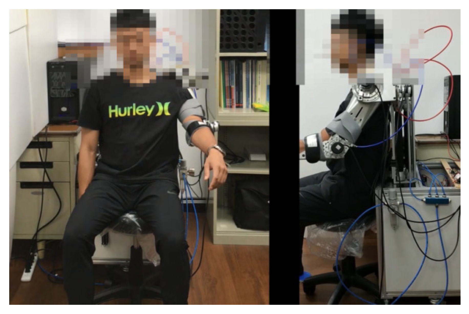
The realization for shoulder internal/external rehabilitation rotation.

Figure 17.
The trajectory of shoulder joint J3.

Figure 18.
Trajectories of shoulder joint J2 with instant spasm occurring.

Figure 19.
Trajectories of shoulder joint J2 with tremor occurring.


Table 1.
Ranges of motion (ROMs) of four active DOFs.
| DOF | Man [18] | Proposed |
|---|---|---|
| Elbow flexion/extension | 135°/0° | 120°/0° |
| Shoulder internal/external rotation | 180°/60° | 150°/45° |
| Shoulder flexion/extension | 135°/45° | 110°/30° |
| Shoulder abduction/adduction | 180°/45° | 150°/30° |
Table 2.
Fuzzy rules for the fuzzy sliding mode controller (FSMC)i.
| FSMC | s | ||||||
|---|---|---|---|---|---|---|---|
| NB | NM | NS | ZO | PS | PM | PB | |
| NB | PB | PB | PB | PB | PM | PS | ZO |
| PM | PB | PB | PB | PM | PS | ZO | NS |
| NS | PB | PB | PM | ZO | ZO | NS | NM |
| ZO | PB | PM | PS | ZO | NS | NM | NB |
| PS | PM | PS | ZO | ZO | NM | NB | NB |
| PM | PS | ZO | NS | NM | NB | NB | NB |
| PB | ZO | NS | NM | NB | NB | NB | NB |
Table 3.
RMSE at joints for the PID, SMC, and FSMC.
| RMSE | Exercise 1 | Exercise 2 | ||
|---|---|---|---|---|
| PID | 17.099 | 10.7635 | 53.3137 | 18.4418 |
| SMC | 3.4161 | 5.2894 | 9.4021 | 17.5915 |
| FSMC | 2.5087 | 3.5783 | 8.2311 | 12.3227 |
Publisher’s Note: MDPI stays neutral with regard to jurisdictional claims in published maps and institutional affiliations. |
© 2020 by the authors. Licensee MDPI, Basel, Switzerland. This article is an open access article distributed under the terms and conditions of the Creative Commons Attribution (CC BY) license (http://creativecommons.org/licenses/by/4.0/).
Share and Cite
MDPI and ACS Style
Chen, C.-T.; Lien, W.-Y.; Chen, C.-T.; Wu, Y.-C. Implementation of an Upper-Limb Exoskeleton Robot Driven by Pneumatic Muscle Actuators for Rehabilitation. Actuators 2020, 9, 106. https://0-doi-org.brum.beds.ac.uk/10.3390/act9040106
AMA Style
Chen C-T, Lien W-Y, Chen C-T, Wu Y-C. Implementation of an Upper-Limb Exoskeleton Robot Driven by Pneumatic Muscle Actuators for Rehabilitation. Actuators. 2020; 9(4):106. https://0-doi-org.brum.beds.ac.uk/10.3390/act9040106
Chicago/Turabian StyleChen, Chun-Ta, Wei-Yuan Lien, Chun-Ting Chen, and Yu-Cheng Wu. 2020. "Implementation of an Upper-Limb Exoskeleton Robot Driven by Pneumatic Muscle Actuators for Rehabilitation" Actuators 9, no. 4: 106. https://0-doi-org.brum.beds.ac.uk/10.3390/act9040106
Note that from the first issue of 2016, this journal uses article numbers instead of page numbers. See further details here.