Fault Estimation and Fault-Tolerant Control for the Pump-Controlled Electrohydraulic System


School of Mechanical and Automotive Engineering, University of Ulsan, Daehakro 93, Nam-gu, Ulsan 44610, Korea
*
Author to whom correspondence should be addressed.
Actuators 2020, 9(4), 132; https://0-doi-org.brum.beds.ac.uk/10.3390/act9040132
Submission received: 14 November 2020
/
Revised: 1 December 2020
/
Accepted: 2 December 2020
/
Published: 5 December 2020
(This article belongs to the Special Issue Advanced Fluid Power Systems and Actuators)
Abstract
:This paper proposes a fault estimation and fault-tolerant control strategy with two observers for a pump-controlled electro-hydraulic system (PCEHS) under the presence of internal leakage faults and an external loading force. The mathematical model of the PCEHS is dedicatedly derived in the state-space form for developing control methodology. Two different observers are developed in which an extended state observer is applied to estimate the internal leakage flow rate, and a disturbance observer is used to deal with the external loading force. Then, the proposed control is designed based on the backstepping sliding mode technique in which estimated information from the observers is taken into consideration to guarantee the working performance of the system. With the proposed methodology, the robustness and stability of the controlled system are theoretically analyzed and proven by the Lyapunov theorem. Comparative simulation results are given to demonstrate the effectiveness of the proposed methodology through different testing conditions.
1. Introduction
Electrohydraulic systems (EHSs) are popularly employed in numerous industrial applications, such as types of heavy machinery, aircraft actuator, robotics, and so on, due to their advantage of generating large force/torque directly [1,2]. Nevertheless, the existence of nonlinearities, uncertainties, and disturbances such as flow properties, friction, internal and external leakages, and uncertain parameters are challenging tasks for developing control strategies to guarantee the desired performance of the electrohydraulic system [3,4]. Various studies of algorithm developments have been published to enhance the system working performance such as nonlinear controls [5,6], adaptive controls [7,8,9], optimal controls [10,11], and observers [12,13,14]. However, these studies essentially focused on improving the position-tracking control, force control, or even the regenerative energy of the hydraulic system without consideration of problems relating to system level or system reliability.
Due to the ever-increasing demand for the stability and safety of hydraulic machinery systems, the impacts of faults or abrupt abnormalities causing the decline of working performance or even serious failures should be considered. In a critical working environment, faults of a hydraulic system such as internal/external leakage in cylinders or valves [15,16], sensor faults (broken, noise, offset) [17,18], vibrations and friction of an actuator [19], and so on, are considered as unknown and uncertain factors that are difficult to measure directly but may easily suddenly occur. These have led to increasing trends towards developing strategies to precisely estimate faults and develop fault-tolerant control (FTC) algorithms that are essential demands as parts of a control system design to maintain control performance [20,21]. Following the literature of the hydraulic system in the relevant fields, many approaches were proposed to estimate the faults such as using Kalman filter (KF) algorithms [22,23], state observers [24,25], adaptive observers [26,27], unknown input observers [28,29], or intelligent approaches [30,31]. Additionally, the accuracy of the estimation fault process was also considered to promptly deal with complex faults, thus improving the reliability of the proposed methods. Furthermore, to maintain system stability and minimize the potential risks in the presence of faults, the FTC method was developed based on the acquired information from the fault estimation process [32,33]. Through fault-tolerant controllers, the system can cancel out the effects caused by the faults or accommodate automatically with faults among components in the system to guarantee the desired level of the overall working performance [34].
In the EHS, internal leakage fault and sensor fault is specifically considered as one of the main reasons impairing working performance or even making the system unstable unless appropriate compensation strategies are taken. This problem has evoked much interest in exploring various topics to tackle this fault in recent times [35,36]. In [37,38,39,40], the authors constructed a method based on extended state observers (ESOs) to estimate uncertain nonlinearities, parametric uncertainties, and external disturbances. The ESO-based control schemes are usually applied not only to give the system states but also estimate the uncertain terms and unknown disturbances by using extended states. In [37,39], the matched and unmatched disturbances of the hydraulic actuator were estimated by linear ESOs and then compensated by the proposed controller to reduce the effects of undesired disturbances. These results revealed that the estimation error converges to zero by increasing the observer bandwidth. In [38,40], the ESOs-based backstepping control algorithm was proposed to handle the load disturbance and mechanical dynamics uncertainties. The superiority of ESOs is indicated through various other engineering applications [19,41,42,43]. The ESO is suitable for dealing with the complicated nonlinear system due to the earning advantages of simple canonical form, ease of implementation, less requirement of system knowledge, and direct generation of estimated parameters through the error of state variables. Another popular method that can be referred to as solving problems of the matched and unmatched uncertainties is a nonlinear disturbance observer (DO). Conventionally, this technique is widely applied to cope with the force disturbance, which is one of the important external impacts to be investigated on the hydraulic system [44,45]. To obtain good position-tracking performance of an electrohydraulic actuator, Wonhee Kim et al. [46] proposed a disturbance observer (DO) in the form of a two-order high-pass filter to estimate the disturbances consisting of external load torque and constant friction. In [47,48], a nonlinear robust controller based on the DO was applied to improve the control accuracy of EHSs in which the DO was considered as a good compensation method to eliminate the effect of external disturbance and model uncertainties. Furthermore, in [49], a high-order DO was developed to guarantee the asymptotic convergence of the observers by using the bounded law of time-varying disturbances combined with the linear and nonlinear functions of the estimation error. Experimental results of this research verified the reliability of the proposed method, where the DO was a suited method to estimate external force disturbance with high accuracy. Essentially, the DO takes advantage of simple principle and structure, high performance and robustness, light computation, and compatibility when combining with other techniques. Although knowledge of the system level is required along with a command input signal and measurable output, this operator still achieves good performance and has some potential. Therefore, a combination of the ESO and DO may lead to interesting topics to be explored for further development and expansions to other relating fields of research, such as data-driven or signal-based processing.
Based on the literature overview, this paper proposes a fault estimation and fault-tolerant control method to maintain the working performance for a PCEHS subject to internal leakage fault and external force disturbance. The mechanical dynamics and hydraulic dynamics of the PCEHS are derived for designing the proposed technique in which the leakage flow rate and varying external payload are considered as primary elements that affect the robustness of the studied system. In order to achieve the abovementioned problems, contributions in this paper can be listed as follows: (1) First, two high-order observers are initially developed in which an extended state observer is used to estimate the internal leakage flow rate, and a disturbance observer is exploited to deal with the external loading force. (2) With the estimated parameters, a fault-tolerant controller-based backstepping sliding mode technique is designed to overcome system instability when the fault occurs. (3) The effectiveness of the observers and control scheme for the whole system is theoretically proved by a Lyapunov theory in the influence of the internal leakage fault and external force disturbances. Numerical simulations are performed with different testing conditions including fault-free, internal leakage fault, change of the external loading force, and variable working frequencies to validate the workability and reliability of the proposed methodology.
The rest of the paper is organized as follows. Section 2 explains the system modeling and problem statement. Next, the model-based fault-tolerant controller is described in Section 3. This proposed control scheme including the extended state observer, disturbance observer, is designed with the stability proof of the whole closed-loop system. Numerical simulations are presented in Section 4 to illustrate the effectiveness of the proposed method under several conditions. Finally, the conclusion and perspective of future works are discussed in Section 5.
2. System Modeling and Problem Statement
2.1. Mechanical Dynamics
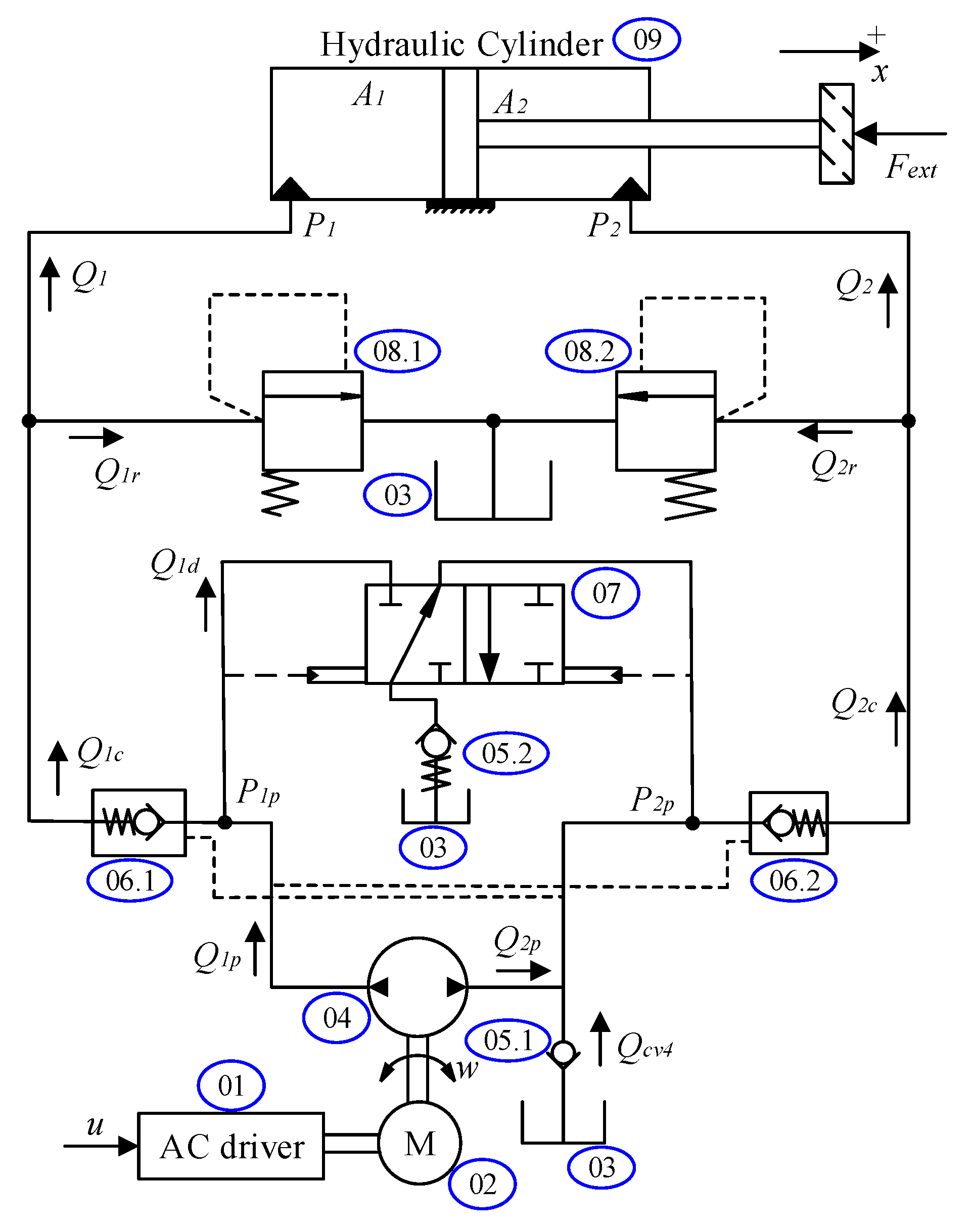
In this research, a one-degree-of-freedom PCEHS driving a double-acting, single-rod hydraulic cylinder is presented in Figure 1. The main components of this system are detailed in Table 1.
For the working principle, the system motion is adjusted by the double-acting single-rod cylinder that is driven by the fixed-displacement gear pump through a control hydraulic circuit. The pump is actuated by the AC driver. Flow differences between the two chambers are compensated by check valves (05.1 and 05.2). The positive direction of the cylinder motion is chosen as shown in Figure 1.
The system dynamics of the actuator by applying Newton’s second law is expressed:
where x and m are the piston position and the mass of the system motion, respectively. and are bore-side and rod-side cross-section areas of the cylinder. and are pressures inside chambers 1 and 2, respectively. refers to a lumped friction, and is an external force of the load.
The term is the lumped friction that can be approximated as follows:
where , , and are positive constants.
2.2. Hydraulic Dynamics
As presented in Figure 1, the PCEHS consists of the hydraulic cylinder, valves, and hydraulic pump system. The PCEHS generates pressures inside the circuit, thus inducing force acting on the cylinder movement. The pressure dynamics inside the cylinder chambers can be described as follows [49]:
where is the effective bulk modulus of the used hydraulic fluid; and are initial volumes in the chamber of bore-side and rod-side, respectively. is the supply flow to chamber 1; is the supply flow to chamber 2; is the discharge flow from chamber 1; is the discharge flow from chamber 2; and is the internal leakage flow inside cylinder chambers. and are the external leakage of the two chambers.
The supply flow rate to the two chambers are calculated separately as follows:
where and are the pump flows; is the discharged flows through the directional valve (07); is the charged flow from the tank through the check valve (05.1); and are flows from the pump through the two pilot check valves (06.1 and 06.2); and and are discharged flows through the relief valves (08.1 and 08.2, respectively). It should be noted that flow rate values and of the relief valves are zero in normal working conditions because these relief valves are overpressure protectors.
The discharged flows from the two chambers are calculated as follows:
The internal leakage inside the cylinder can be linearly approximated as
where is the internal leakage coefficient of the main cylinder.
The pump flow functions can be presented as follows:
where is the volumetric efficiency of the pump; is the pump displacement; is the pump speed; is the internal leakage of the pump; and and are external leakages of the pump.
The internal leakage flow of the pump can be calculated as
where is the coefficient of internal leakages of the pump. is the pump displacement. is the inertia moment of the pump. is the coefficient of viscous friction torque of the pump.
The controller inside the motor driver is simplified, such that pump speed can be expressed by a linear function of input voltage as
Assumption 1.
(a) The hydraulic energy is not lost on the transferred pipelines. (b) All external leakages are neglected:
From (7) to (10), the pump flow function can be rewritten:
where ; .
The used hydraulic fluid is incompressible. Hence, the flows of the directional valve (07) and check valve (05.1) can be approximated as follows:
where is a positive constant.
The flows through the pilot check valves can be approximated as follows:
where is the flow discharge coefficient; and are the instantaneous orifice passage areas of the pilot check valve 06.1 and pilot check valve 06.2, respectively; is the fluid density; and are pressures of the pump to the pilot check valves (06.1 and 06.2); and are equivalent pressures differential across the control member; is the valve cracking pressure; is the pressure needed to fully open the valve; is the valve gain coefficient; is the pilot ratio; is the closed valve leakage area; and is the fully open valve passage area.
The state variables of the system are defined as . Then a full model of the studied system is presented in state-space form as
where is the leakage flow inside the cylinder, and the detailed dynamics functions are summarized as
The parameters of the obtained model show that this PCEHS is an uncertain nonlinear system. In practice, the term is hard to define exactly. Values of and change during working processes. , , and m are also uncertain. Therefore, ensuring the tracking performance in the presence of disturbances and internal leakage faults is a difficult task. For conveniently designing the observers and controller, the following assumptions are presented:
Assumption 2.
The system variables are measurable and bounded.
Assumption 3.
The term g is Lipschitz concerning ; is Lipschitz for ; is Lipschitz for and in the practice range.
3. Fault-Observer-Based Tolerant Controller Design
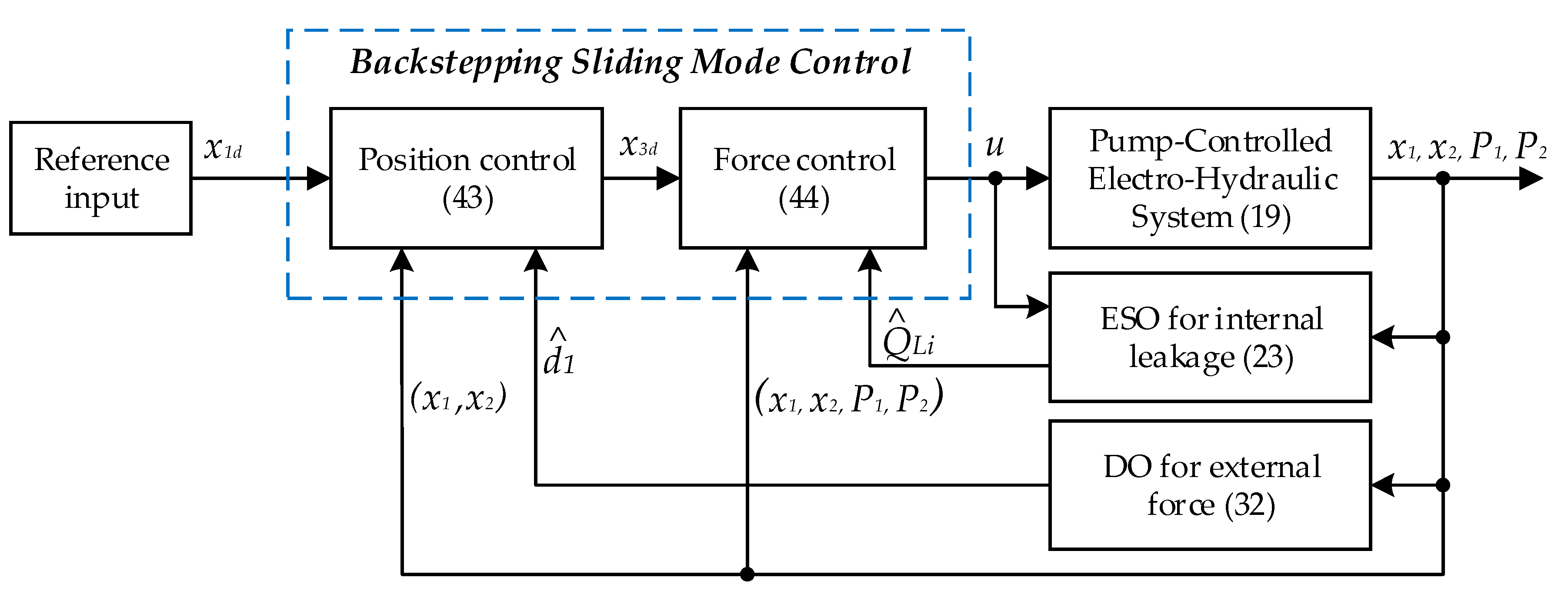
In this section, an FTC strategy is proposed to execute the control objectives. The values of the internal leakage and external force disturbances are estimated by two different observers through full state feedback. A nonlinear controller using the estimated information is designed by the sliding mode and a backstepping technique. The diagram of the proposed strategy is depicted in Figure 2.
Assumption 4.
The force disturbance is bounded. Its time derivative is also bounded, and there always exists a virtual bounded disturbance [49] satisfying
where and are the positive constants.
3.1. Extended State Observer for Internal Leakage Fault Estimation
In this part, the ESO is applied to estimate the existing state vector and the extended state that includes the internal leakage fault based on the output and control input signals. We define as an extended state variable and is the time derivative of . Here, is assumed to be unknown but bounded as , where is a positive constant. By referring to [39], the last equations of (19) and extended state variable can be rewritten as follows:
The observer is proposed as follows:
where the observer parameters are positive constants. The term is an arbitrarily small positive constant.
In this research, the most important role of the ESO is to estimate the internal leakage flow inside the hydraulic cylinder as
Let denote the estimation errors between the actual and estimated values, i.e., . The dynamics of the state estimation error can be expressed by using (22) and (23) as
Assumption 5.
The estimation error changes with respect to time, and it is bounded with the appropriate constant .
Define as the scaled estimation error. Then, Function (25) can be written as
where and
in which A is Hurwitz.
Therefore, there exists a positive definite matrix satisfying the following equation:
Consider a Lyapunov function as follows:
The proofs of function are presented in Appendix A, in which the result is obtained as follows:
3.2. Disturbance Observer for External Force Estimation
From the second equation of (19) and Assumption 4, the dynamics of the external force disturbance model is proposed as
where is defined as .
By referring to [49], a new estimation model can be constructed as follows:
where are positive constants; is the estimated value of ; and is the estimated value of .
Subtracting (32) from (31), the estimation error of the force dynamics can be derived as
where and .
Assumption 6.
The estimation error is time-varying and is bounded .
Lemma 1.
Considering Assumption 3 and the bounded system (21), the estimation system is asymptotic stable if the used positive gains satisfy the following conditions.
Proof of Lema 1.
The non-negative definite Lyapunov function is expressed as
where the additions of and positive term are determined as follows [49]:
The proofs of the function are presented in Appendix B. The time derivative is obtained as
□
3.3. Backstepping Sliding Mode Controller Design
In this subsection, the controller based on the sliding-mode backstepping technique is proposed to guarantee the robustness of the PCEHS based on the estimated information of external force and internal leakage flow.
Step 1: The virtual control law is designed to ensure the position-tracking error to be as small as possible.
First, we choose the sliding surface as
where is a positive constant; ; ; is the desired trajectory, and .
The time derivative of the sliding surface is derived as
We define the virtual control as
where are arbitrary positive constants, and is the estimated result of the term .
We then define the different pressure error as follows:
Step 2: The controller is designed to ensure the robustness of the system under the presence of the internal leakage fault. The differential of this state error is:
In Equation (42), the time derivative of the virtual control signal may be invalid because Equation (40) contains a signum function as a discontinuous term. Thus, this function is replaced by a hyperbolic tangent function. The virtual control signal is rewritten as follows:
Hence, the final control signal is chosen as follows:
where , and are arbitrary positive constants, and the term is defined as .
The tanh function is defined as
3.4. Stability Analysis
Theorem 1.
The control laws in (40) and (44) incorporated with the ESO in (23), and the disturbance observer in (32) guarantee the stability of the closed-loop system for all bounded positive control gains and the bounded disturbances estimated.
Proof of Theorem 1.
For the closed-loop performance, a new Lyapunov function is considered as follows:
The time derivative of the function in (46) is
Substituting (39), (42), (43), and (44) into Equation (47), the obtained result is:
where .
The inequality in (48) shows that the system is uniformly ultimately bounded [9].
To prove the stability of the whole system, the comprehensive Lyapunov function is considered as
The time derivative of Equation (49) is expressed as follows:
where and .
From Ref. [13], it can be seen that the proposed control is ultimately uniformly bounded in the presence of force disturbance and internal leakage fault. As a result, the Lyapunov function (49) is bounded by
Thus, both the tracking error and the disturbances’ estimated errors are bounded. This proves the results in Theorem 1. □
4. Simulation Results
4.1. Simulation Descriptions
In this section, the proposed methodology conducted for the PCEHS is examined in several simulations to evaluate its workability. The simulations are implemented by the Matlab2019b/Simulink program with a sample time of 0.001 s. According to the description in [51], the nominal values of the system parameters are presented in Table 2. Furthermore, the gains of the proposed controller and two observers are selected based on the model-based identification method [49] and are presented in Table 3 and Table 4, respectively.
To investigate the effectiveness of the proposed control, a conventional proportional-intergral-derivative (PID) and direct backstepping (DBS) controllers are employed under the same testing conditions for comparisons. The PID gains are obtained from manually tuning such that the best system performance can be exhibited. By referring to [7], the DBS controller is designed as Equation (53). The estimated terms in the DBS controller are originally followed by Equations (24) and (32).
4.2. Simulation Results
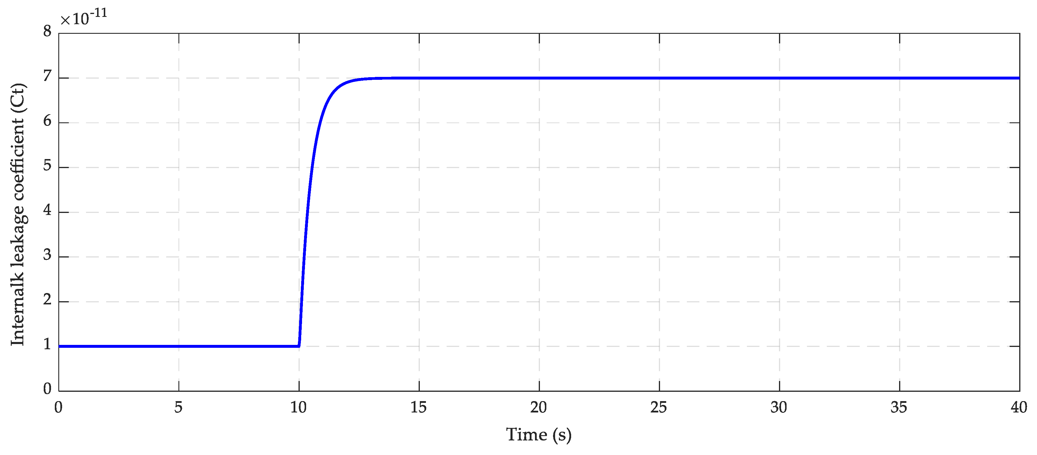
In this scope, it is notable that we concentrate on the investigations of the system robustness in the presence of internal leakage fault. To evaluate the influence of internal leakage on the working performance of the PCEHS system, the leakage coefficient profile is set as described in Figure 3. As can be seen, we suppose that in the fault-free condition, the leakage coefficient is smaller or equal to , corresponding to the working time from 0 to the 10th second. After that, this coefficient gradually increases in an interval of 2 s, which describes the state transition between normal working condition and internal leakage condition. The internal leakage fault happens at the time of the 12th second if the coefficient reaches a threshold of or greater.
4.2.1. The First Simulation Case
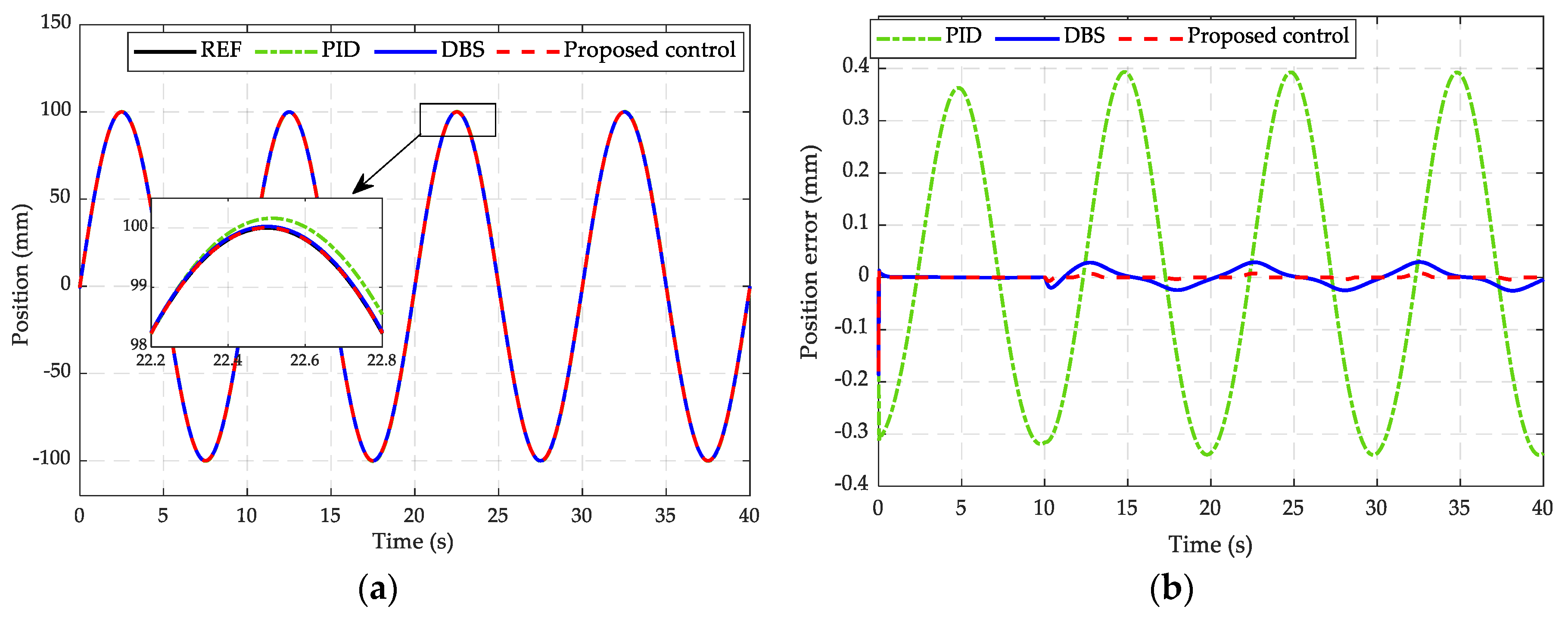
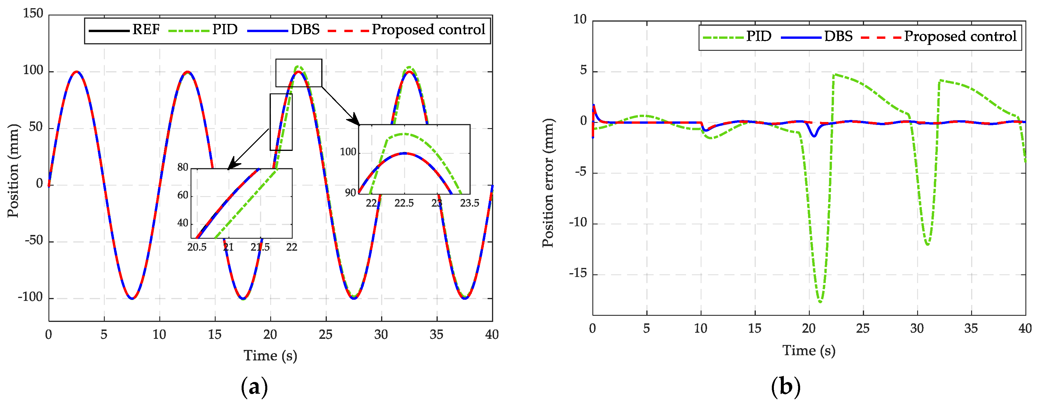
In the first simulation, the desired input trajectory is employed as a sinusoidal signal with an amplitude of 100 mm and frequency of 0.1 Hz , and no external loading force is applied, kN. Because the external force is not considered, this simulation case mainly focuses on evaluating the robustness of the system when the leakage occurs. The tracking performances of the proposed and the other two controllers are presented in Figure 4 in which the continuous black line represents the reference input signal (REF), the dot-dash green line represents the PID controller (PID), the continuous blue line represents the direct backstepping controller (DBS), and the dash red line represents the proposed controller.
In Figure 4a, the position-tracking performances of the three controllers are presented, while the corresponding comparative tracking errors are depicted in Figure 4b. As can be seen, in the fault-free condition, the PID controller takes an error in the range of mm, while the DBS controller obtains a smaller tracking error approximated at mm, and the proposed controller achieves the highest control accuracy with the error converging to mm. After 10 s of the working process, the internal leakage coefficient increases, thereby resulting in the internal leakage fault occurrence that makes the system lose efficiency. In the leakage fault condition, the tracking error from using the PID controller is in the range of mm. Improved control precision could be accomplished by tuning greater PID gains, but the control output could exceed its limits at the time and could not guarantee system reliability in the wide spectrum of operations. To relieve the effect of system dynamics on the quality of control, the DBS controller is applied wherein the influence of fault on the PCEHS model is compensated by the DBS technique. As a result, the smaller tracking error converges in the range of mm. To increase the control quality, the proposed methodology is employed in which the internal leakage fault is handled by the extended state observer, and more stable system behavior is achieved from using the backstepping sliding mode technique. The best control accuracy is obtained where the tracking error converges in the range of mm. This reveals that the proposed methodology is able to guarantee the accuracy and robustness of the system not only in the fault-free condition but also in the presence of the internal leakage fault.
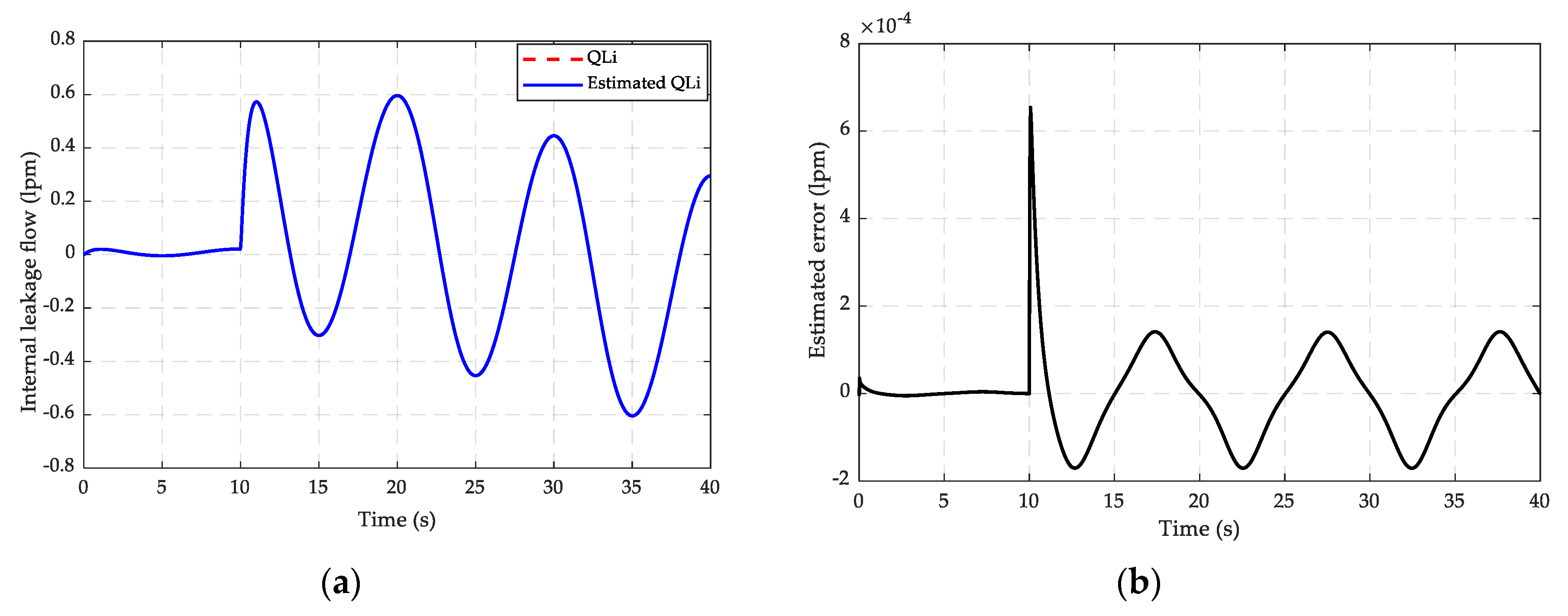
The estimation result of the internal leakage is shown in Figure 5 in which Figure 5a displays the estimated internal leakage flow, while the estimated error is plotted in Figure 5b. Here, it can be seen that the estimated internal leakage fault can track the actual one that occurs at the time of the 10th second when the amplitude of internal leakage flow increases in the range of lit/min. The proposed observer guarantees that the asymptotic converges to the smallest error bounded by lit/min.
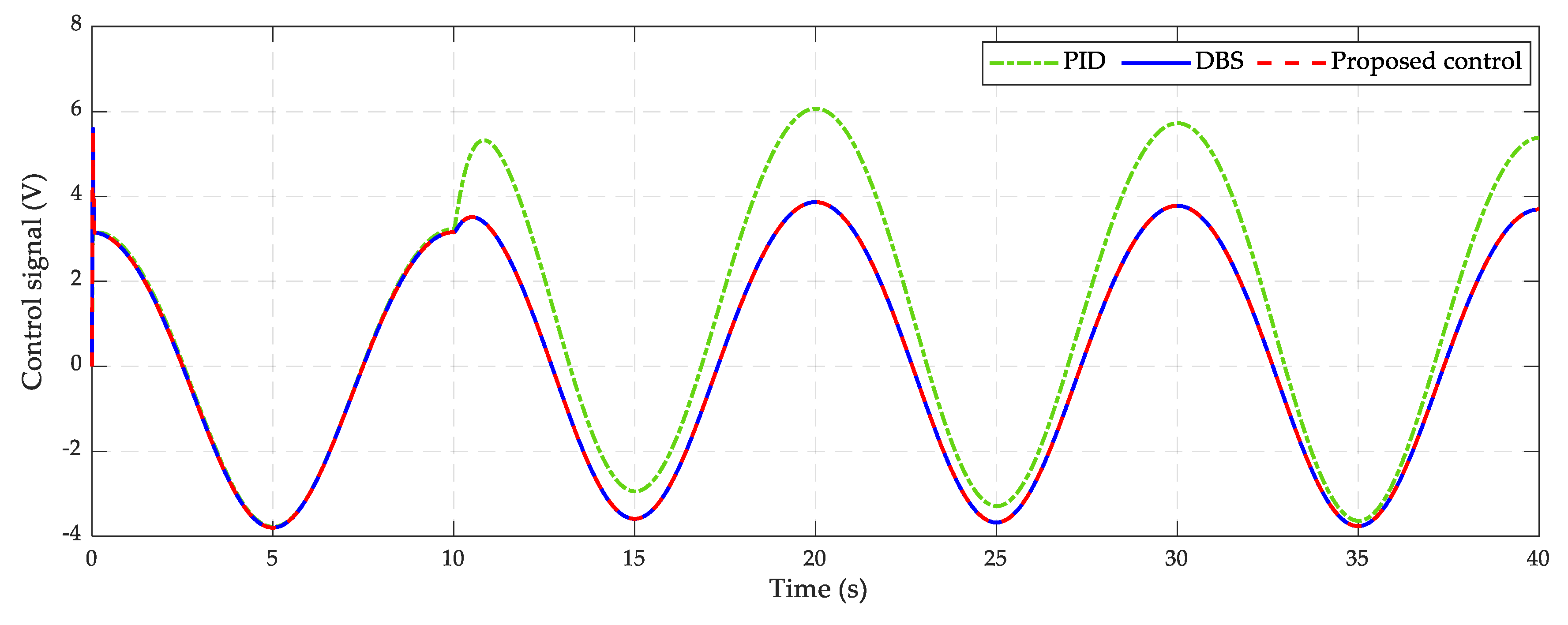
Figure 6 displays control signals in which the control input of the proposed methodology is the smallest compared with those of the PID and DBS. There is a significant rising in the PID control input signal in the presence of internal leakage fault.
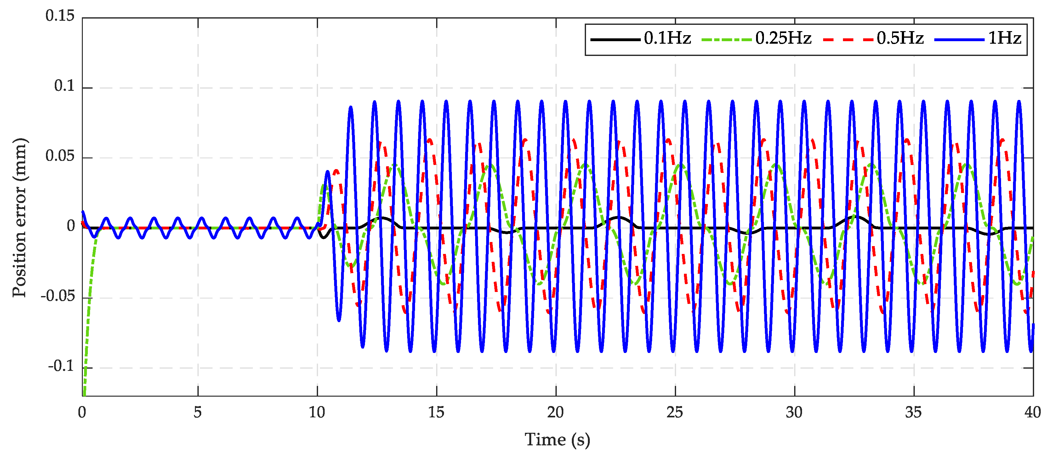
Furthermore, in order to investigate the more challenging working condition for the proposed control strategy, high-frequency reference inputs are given with different sinusoidal signals. In practice, the hydraulic system normally works in low frequency. Increasing the frequency of the reference with the same amplitude may cause the actuator response to fail in adapting to the desired setup. Therefore, it is necessary to select the reference input signal with the appropriate frequency and amplitude. Referring to [7,49], the frequency and amplitude of the desired trajectory are considered with four profiles of (0.1 Hz, 100 mm), (0.25 Hz, 50 mm), (0.5 Hz, 20 mm), and (1 Hz, 10 mm). The comparative simulation results in the condition of no loading force are compared in Figure 7. This figure shows that in the normal working condition, the control effort guarantees small errors at the frequency from 0.1 to 0.5 Hz and slightly big errors at the 1 Hz frequency. Meanwhile, in the internal leakage fault condition, the system response is significantly degraded at high frequencies. In the 0.1 Hz test, the proposed controller is stable with the smallest tracking error inside a range of mm. However, this tracking error is expanded from mm at the 0.25 Hz excitation to mm at the 0.5 Hz excitation, and the largest error in the range of mm is generated at the 1 Hz frequency. As a result, the proposed controller presents the highest effectiveness at 0.1 Hz frequency with no loading force condition and the presence of internal leakage fault.
4.2.2. The Second Simulations Case
In the second simulation, the tracking effort and robustness of the PCEHS system are investigated under the presence of both internal leakage fault and external load condition at 4000 N. Similar to the first case study, we suppose that the desired trajectory is a sinusoidal signal with an amplitude of 100 mm and a frequency of 0.1 Hz , and that the internal leakage phenomenon happens at the time of the 12th second. The system tracking performances and estimation parameters are depicted from Figure 8, Figure 9, Figure 10 and Figure 11.
As can be seen in Figure 8, in the fault-free environment, the tracking performances under the PID, DBS, and the proposed controller are degraded with the tracking error mm of the PID, mm of the DBS, and mm of the proposed control. When the internal leakage fault occurs, the figure remarks that the PID response is significantly degraded with the position-tracking error in the range of mm. The control accuracy is improved up to mm under the DBS controller. Due to the benefit of the two proposed observers and the backstepping sliding mode technique, the proposed methodology achieves superior performance with the smallest error in the range of mm. Generally, the proposed control strategy can maintain the working performance of the system in the heavy-load condition and internal leakage fault.
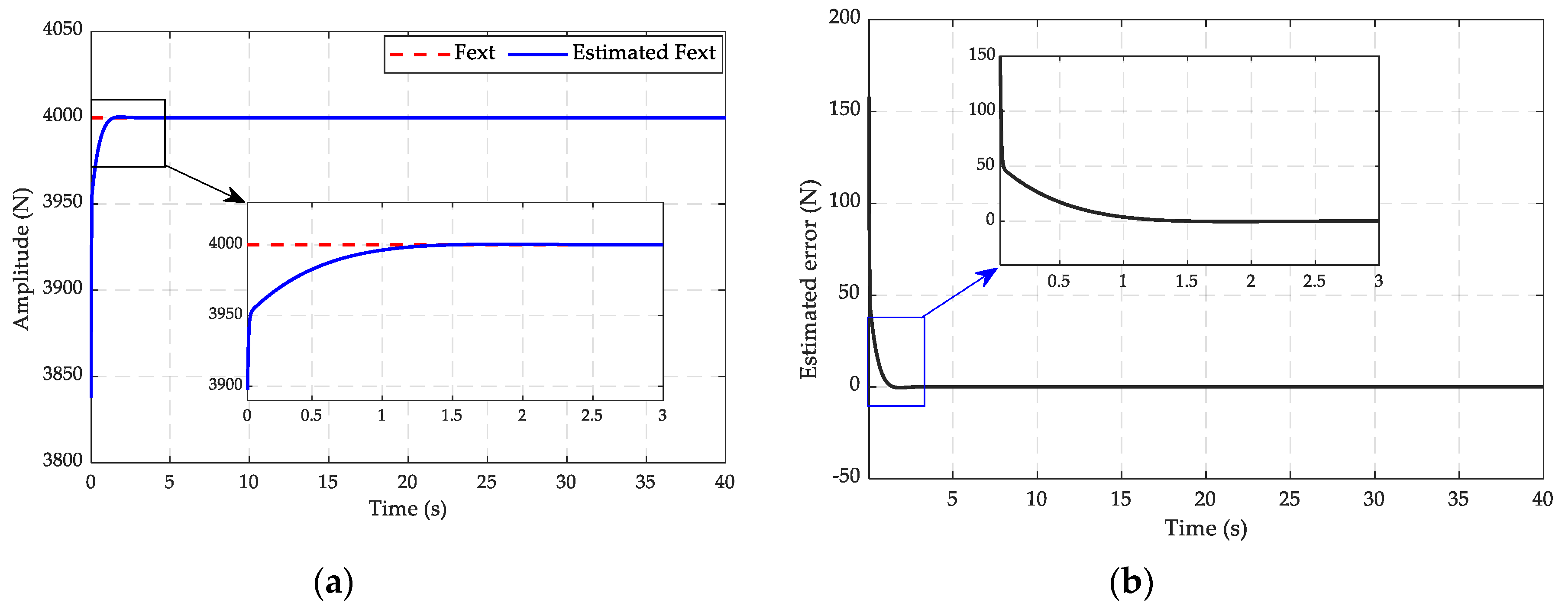
Figure 9 and Figure 10 show the estimated results of the external force and internal leakage flow, respectively. In particular, the estimated error of the external loading force converges to zero after 1.5 s. Moreover, this external force is the major term that directly affects the pressure dynamics of the system, thus causing the amplitude of internal leakage flow to increase higher. As revealed in Figure 10, the internal leakage fault occurs at the time of the 12th second where the amplitude of the flow rate significantly grows to nearly 11 lit/min in comparison with that in the case of a no external load condition. In spite of this, the system behavior is maintained in good qualification due to employing the ESO to estimate and compensate the influence of the internal leakage. The estimated error is accomplished in the range of lit/min. As a result, the proposed methodology can guarantee the asymptotic convergence to the smallest error. In addition, the control input signals, which are constrained in the interval of , are performed in Figure 11. As a result, the proposed control strategy has the smallest control signal over those of the PID and DBS when saturated at 10VDC in the presence of a fault.
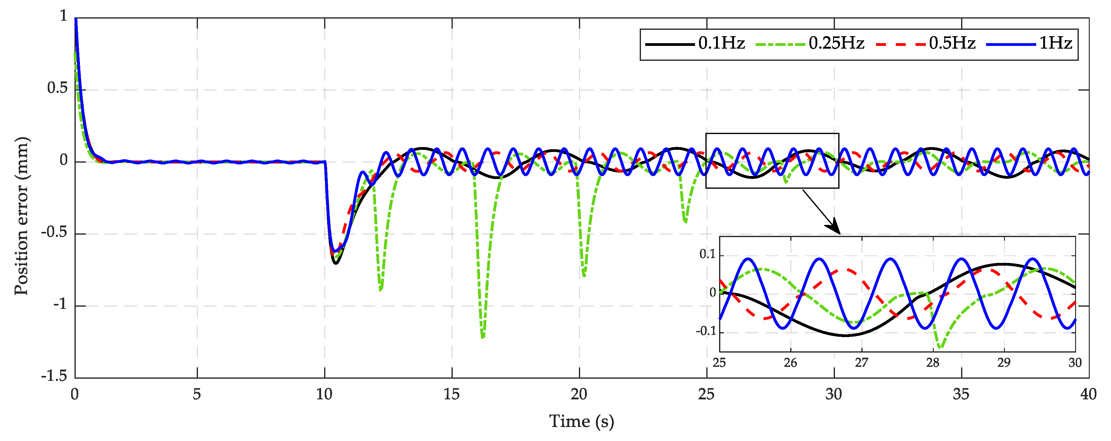
Finally, similar to the first simulation case, the performance of the proposed controller is also examined in different frequency conditions with four profiles as (0.1 Hz, 100 mm), (0.25 Hz, 50 mm), (0.5 Hz, 20 mm), and (1 Hz, 10 mm). The position-tracking errors with an external loading force of about 4000 N are compared in Figure 12. The simulated results show that in the normal working condition, the tracking error achieves a limited value at a frequency from 0.1 to 1 Hz. On the contrary, the response of four signal lines significantly changes in the transition period between normal and fault states at the time from the 10th second to the 12th second with a range of variations reaching −0.7 mm. When the leakage fault occurs, the tracking errors maintain a steady state with a range of mm at the frequencies of 0.1, 0.5, and 1 Hz. In the 0.25 Hz test, there is a large tracking error with amplitude from −1.25 to 0.1 mm in the interval of s. Then, this error preserves the limitation of about mm. Additionally, one can observe that applied higher frequencies lead to more chattering phenomenon. Therefore, considerations of chattering-free at a high frequency or increasing the adaptive bandwidth of the control laws and observers may lead to the exploration of interesting topics for further development.
5. Conclusions
In this paper, we dedicatedly presented the methodology for solving the problems of fault estimation and fault-tolerant control for the PCEHS. In this examined scenario, the internal leakage fault was considered as a major factor for losing the working performance of the system. In addition, the impacts of an external loading force and variable frequency input signals were also systematically investigated due to its remarkable influence on the output behavior. In order to deal with those obstacles and achieve the output tracking requirement, the extended state observer and the disturbance observer were developed to estimate internal leakage and the external loading force, respectively. According to these estimated parameters, the backstepping sliding mode controller was employed due to its advantages of system robustness and global stability assurance. The stability of the whole closed-loop system in which both the controller and the proposed observer were taken into consideration was mathematically proved by the Lyapunov approach. Based on the constructed strategy, comparative simulations between the proposed control scheme with the other two conventional PID and direct backstepping (DBS) controllers were implemented on the PCEHS under different working conditions. The simulated results evidently confirmed the superior effectiveness of the proposed strategy over the other two in maintaining the system performance under the presence of the internal leakage fault and varying external loading force. It is noteworthy in this scope that the internal leakage coefficient is supposed to gradually increase and be maintained at a constant value. Indeed, this parameter can have stochastic forms with transient amplitude or increase over time depending on the working process. Therefore, the proposed methodology in this work is a premise for further algorithm development to deal with other real challenges such as incipient faults detection, fault positions isolation; to maintain system performance in the presence of actuator faults, sensor faults, or faults with consideration of input saturation or output constraints; or to expand other relating fields of research. Furthermore, adaptive laws or approximation methods can be systematically integrated for adapting control parameters to enhance the working requirements.
Author Contributions
K.K.A. was the supervisor providing funding and administrating the project, and he reviewed and edited the manuscript. H.V.A.T. checked all the manuscript, discussed, and supported the design of the proposed algorithm and simulations. H.A.T. carried out the investigation, proposed the methodology, analysis, and validations by using the MATLAB software for simulations, and wrote the original manuscript. All authors have read and agreed to the published version of the manuscript.
Funding
This research was supported by the Basic Science Research Program through the National Research Foundation of Korea (NRF) funded by the Ministry of Science and ICT, South Korea (NRF-2020R1A2B5B03001480).
Conflicts of Interest
The authors declare no conflict of interest.
Appendix A
Its time derivative expression can be written as
Appendix B
The time derivative of the Lyapunov function in (45) can be analyzed by using Equations (41), (42), and (44) as follows:
where
References
- Alle, N.; Hiremath, S.S.; Makaram, S.; Subramaniam, K.; Talukdar, A. Review on electro hydrostatic actuator for flight control. Int. J. Fluid Power 2016, 17, 125–145. [Google Scholar] [CrossRef]
- Jelali, M.; Kroll, A. Hydraulic Servo-Systems: Modelling, Identification and Control; Springer Science & Business Media: Berlin/Heidelberg, Germany, 2003. [Google Scholar]
- Koivumäki, J.; Mattila, J. High performance nonlinear motion/force controller design for redundant hydraulic construction crane automation. Autom. Constr. 2015, 51, 59–77. [Google Scholar] [CrossRef]
- Yao, J.; Jiao, Z.; Ma, D.; Yan, L. High-Accuracy Tracking Control of Hydraulic Rotary Actuators with Modeling Uncertainties. IEEE/ASME Trans. Mechatron. 2013, 19, 633–641. [Google Scholar] [CrossRef]
- Do, T.C.; Tran, D.T.; Dinh, T.Q.; Ahn, K.K. Tracking control for an Electro-hydraulic rotary actuator using fractional order fuzzy PID controller. Electronics 2020, 9, 926. [Google Scholar] [CrossRef]
- Tri, N.M.; Nam, D.N.C.; Park, H.G.; Ahn, K.K. Trajectory control of an electro hydraulic actuator using an iterative backstepping control scheme. Mechatronics 2015, 29, 96–102. [Google Scholar] [CrossRef]
- Ahn, K.K.; Nam, D.N.C.; Jin, M. Adaptive backstepping control of an electrohydraulic actuator. IEEE/ASME Trans. Mechatron. 2014, 19, 987–995. [Google Scholar] [CrossRef]
- Tri, N.M.; Ba, D.X.; Ahn, K.K. A Gain-Adaptive Intelligent Nonlinear Control for an Electrohydraulic Rotary Actuator. Int. J. Precis. Eng. Manuf. 2018, 19, 665–673. [Google Scholar] [CrossRef]
- Tran, D.T.; Ba, D.X.; Ahn, K.K. Adaptive Backstepping Sliding Mode Control for Equilibrium Position Tracking of an Electrohydraulic Elastic Manipulator. IEEE Trans. Ind. Electron. 2020, 67, 3860–3869. [Google Scholar] [CrossRef]
- Guo, H.; Wei, T.; Ding, X.; Duan, C. Multi-Objective Optimal Design of Electro-Hydrostatic Actuator Driving Motors for Low Temperature Rise and High Power Weight Ratio. Energies 2018, 11, 1173. [Google Scholar] [CrossRef] [Green Version]
- Ali, A.; Farid, S.; Saeed, H. Adaptive reliable H∞ control of uncertain affine nonlinear systems. Int. J. Control. Autom. Syst. 2018, 16, 2665–2675. [Google Scholar] [CrossRef]
- Tran, D.-T.; Do, T.-C.; Ahn, K.K. Extended High Gain Observer-Based Sliding Mode Control for an Electro-hydraulic System with a Variant Payload. Int. J. Precis. Eng. Manuf. 2019, 20, 2089–2100. [Google Scholar] [CrossRef]
- Yao, J.; Jiao, Z.; Ma, D. Extended-State-Observer-Based Output Feedback Nonlinear Robust Control of Hydraulic Systems with Backstepping. IEEE Trans. Ind. Electron. 2014, 61, 6285–6293. [Google Scholar] [CrossRef]
- Won, D.; Kim, W.; Shin, D.; Chung, C.C. High-Gain Disturbance Observer-Based Backstepping Control with Output Tracking Error Constraint for Electro-Hydraulic Systems. IEEE Trans. Control. Syst. Technol. 2015, 23, 787–795. [Google Scholar] [CrossRef]
- Athanasatos; Koulocheris, D.; Costopoulos, T.; Raptis, K. Operational fault diagnosis in industrial hydraulic systems through modeling the internal leakage of its components. Am. J. Appl. Sci. 2013, 10, 1648–1659. [Google Scholar] [CrossRef] [Green Version]
- Werlefors, M.; Medvedev, A. Observer-based leakage detection in hydraulic systems with position and velocity feedback. In Proceedings of the 17th IEEE International Conference on Control Applications, San Antonio, TX, USA, 3–5 September 2008; pp. 948–953. [Google Scholar]
- Liu, M.; Cao, X.; Shi, P. Fuzzy-Model-Based Fault-Tolerant Design for Nonlinear Stochastic Systems Against Simultaneous Sensor and Actuator Faults. IEEE Trans. Fuzzy Syst. 2013, 21, 789–799. [Google Scholar] [CrossRef]
- Xia, J.; Jiang, B.; Zhang, K. Robust Asymptotic Estimation of Sensor Faults for Continuous-time Interconnected Systems. Int. J. Control. Autom. Syst. 2019, 17, 3170–3178. [Google Scholar] [CrossRef]
- Luo, C.; Yao, J.; Gu, J. Extended-state-observer-based output feedback adaptive control of hydraulic system with continuous friction compensation. J. Frankl. Inst. 2019, 356, 8414–8437. [Google Scholar] [CrossRef]
- Gao, Z.; Cecati, C.; Ding, S.X. A Survey of Fault Diagnosis and Fault-Tolerant Techniques—Part I: Fault Diagnosis with Model-Based and Signal-Based Approaches. IEEE Trans. Ind. Electron. 2015, 62, 3757–3767. [Google Scholar] [CrossRef] [Green Version]
- Gao, Z.; Cecati, C.; Ding, S.X. A Survey of Fault Diagnosis and Fault-Tolerant Techniques Part II: Fault Diagnosis with Knowledge-Based and Hybrid/Active Approaches. IEEE Trans. Ind. Electron. 2015, 62, 1. [Google Scholar] [CrossRef] [Green Version]
- Wang, X.; Syrmos, V.L. Fault detection, identification and estimation in the electro-hydraulic actuator system using EKF-based multiple-model estimation. In Proceedings of the 2008 16th Mediterranean Conference on Control and Automation; Institute of Electrical and Electronics Engineers (IEEE), Ajaccio, Corsica, France, 25–27 June 2008; pp. 1693–1698. [Google Scholar]
- Mahulkar, V.; Adams, D.E.; Derriso, M. Derivative free filtering in hydraulic systems for fault identification. Control. Eng. Pr. 2011, 19, 649–657. [Google Scholar] [CrossRef]
- Hua, X.; Darong, H.; Guo, S. Extended State Observer Based on ADRC of Linear System with Incipient Fault. Int. J. Control. Autom. Syst. 2019, 18, 1425–1434. [Google Scholar] [CrossRef]
- Tian, L.; Qian, L.; Li, M.; Fu, J.W. Faults Detection Using Sliding Mode Observer and Its Application on Elevating Servo Systems. J. Control. Sci. Eng. 2019, 2019, 1–13. [Google Scholar] [CrossRef]
- Yacun, G.; Lifan, L.; Lina, Y. Fault Diagnosis and Statistical Information Tracking Fault Tolerant Control for Non-Gaussian Non-linear Stochastic Systems. Int. J. Control. Autom. Syst. 2018, 16, 2303–2311. [Google Scholar] [CrossRef]
- Bahrami, M.; Naraghi, M.; Zareinejad, M. Adaptive super-twisting observer for fault reconstruction in electro-hydraulic systems. ISA Trans. 2018, 76, 235–245. [Google Scholar] [CrossRef] [Green Version]
- Haoshuang, C.; Dongsheng, D.; Dewen, Z.; Yan, Y. UIO-based Fault Estimation and Accommodation for Nonlinear Switched Systems. Int. J. Control. Autom. Syst. 2019, 17, 435–444. [Google Scholar] [CrossRef]
- Xu, Q.-N.; Lee, K.-M.; Zhou, H.; Yang, H.-Y. Model-Based Fault Detection and Isolation Scheme for a Rudder Servo System. IEEE Trans. Ind. Electron. 2015, 62, 2384–2396. [Google Scholar] [CrossRef]
- Chen, F.; Lu, D.; Li, X. Robust Observer Based Fault-tolerant Control for One-sided Lipschitz Markovian Jump Systems with General Uncertain Transition Rates. Int. J. Control. Autom. Syst. 2019, 17, 1614–1625. [Google Scholar] [CrossRef]
- Sim, H.Y.; Ramli, R.; Saifizul, A.; Soong, M.F. Detection and estimation of valve leakage losses in reciprocating compressor using acoustic emission technique. Measurment 2020, 152, 107315. [Google Scholar] [CrossRef]
- Jiang, J.; Yu, X. Fault-tolerant control systems: A comparative study between active and passive approaches. Annu. Rev. Control. 2012, 36, 60–72. [Google Scholar] [CrossRef]
- Blanke, M.; Kinnaert, M.; Lunze, J.; Staroswiecki, M. Diagnosis and Fault-Tolerant Control; Springer: Berlin/Heidelberg, Germany, 2016. [Google Scholar]
- Chen, G.; Song, Y.-D. Robust fault-tolerant cooperative control of multi-agent systems: A constructive design method. J. Frankl. Inst. 2015, 352, 4045–4066. [Google Scholar] [CrossRef]
- Choux, M. Nonlinear, Adaptive and Fault-tolerant Control for Electro-hydraulic Servo Systems. Ph.D. Thesis, Technical University of Denmark, Lyngby, Denmark, 2011. [Google Scholar]
- Leuschen, M.L.; Walker, I.D.; Cavallaro, J.R. Nonlinear Fault Detection for Hydraulic Systems. In Fault Diagnosis and Fault Tolerance for Mechatronic Systems; Springer: Berlin/Heidelberg, Germany, 2007; Volume 1, pp. 169–191. [Google Scholar]
- Li, T.; Yang, T.; Cao, Y.; Xie, R.; Wang, X. Disturbance-Estimation Based Adaptive Backstepping Fault-Tolerant Synchronization Control for a Dual Redundant Hydraulic Actuation System With Internal Leakage Faults. IEEE Access 2019, 7, 73106–73119. [Google Scholar] [CrossRef]
- Guo, Q.; Zhang, Y.; Celler, B.; Su, S. Backstepping Control of Electro-Hydraulic System Based on Extended-State-Observer with Plant Dynamics Largely Unknown. IEEE Trans. Ind. Electron. 2016, 63, 6909–6920. [Google Scholar] [CrossRef]
- Yao, J.; Deng, W. Active Disturbance Rejection Adaptive Control of Hydraulic Servo Systems. IEEE Trans. Ind. Electron. 2017, 64, 8023–8032. [Google Scholar] [CrossRef]
- Wang, C.; Zhang, Z.; Wang, H.; Zhao, B.; Quan, L. Disturbance observer-based output feedback control of hydraulic servo system considering mismatched uncertainties and internal pressure dynamics stability. IET Control. Theory Appl. 2020, 14, 1046–1056. [Google Scholar] [CrossRef]
- Tran, D.T.; Jin, M.; Ahn, K.K. Nonlinear Extended State Observer Based on Output Feedback Control for a Manipulator with Time-Varying Output Constraints and External Disturbance. IEEE Access 2019, 7, 156860–156870. [Google Scholar] [CrossRef]
- Jun, G.H.; Ahn, K.K. Extended-State-Observer-Based Nonlinear Servo Control of An Electro-Hydrostatic Actuator. J. Drive Control 2017, 14, 61–70. [Google Scholar]
- Tran, D.T.; Dao, H.V.; Dinh, T.Q.; Ahn, K.K. Output Feedback Control via Linear Extended State Observer for an Uncertain Manipulator with Output Constraints and Input Dead-Zone. Electronics 2020, 9, 1355. [Google Scholar] [CrossRef]
- Truong, D.Q.; Ahn, K.K. Force control for hydraulic load simulator using self-tuning grey predictor - fuzzy PID. Mechatronics 2009, 19, 233–246. [Google Scholar] [CrossRef]
- Truong, D.Q.; Ahn, K.K. Force control for press machines using an online smart tuning fuzzy PID based on a robust extended Kalman filter. Expert Syst. Appl. 2011, 38, 5879–5894. [Google Scholar] [CrossRef]
- Kim, W.; Shin, D.; Won, D.; Chung, C.C. Disturbance-Observer-Based Position Tracking Controller in the Presence of Biased Sinusoidal Disturbance for Electrohydraulic Actuators. IEEE Trans. Control. Syst. Technol. 2013, 21, 2290–2298. [Google Scholar] [CrossRef]
- Sun, C.; Fang, J.; Wei, J.; Hu, B. Nonlinear Motion Control of a Hydraulic Press Based on an Extended Disturbance Observer. IEEE Access 2018, 6, 18502–18510. [Google Scholar] [CrossRef]
- Has, Z.; Rahmat, M.F.; Husain, A.R.; Ahmad, M.N. Robust Precision Control for a Class of Electro-Hydraulic Actuator System based on Disturbance Observer. Int. J. Precis. Eng. Manuf. 2015, 16, 1753–1760. [Google Scholar] [CrossRef]
- Ba, D.X.; Dinh, T.Q.; Bae, J.; Ahn, K.K. An Effective Disturbance-Observer-Based Nonlinear Controller for a Pump-Controlled Hydraulic System. IEEE/ASME Trans. Mechatron. 2019, 25, 32–43. [Google Scholar] [CrossRef]
- Zheng, Q.; Gaol, L.Q.; Gao, Z. On stability analysis of active disturbance rejection control for nonlinear time-varying plants with unknown dynamics. In Proceedings of the 46th IEEE Conference on Decision and Control; Institute of Electrical and Electronics Engineers (IEEE), New Orleans, LA, USA, 12–14 December 2007; pp. 3501–3506. [Google Scholar]
- Ba, D.X.; Ahn, K.K.; Truong, D.Q.; Park, H.G. Integrated model-based backstepping control for an electro-hydraulic system. Int. J. Precis. Eng. Manuf. 2016, 17, 565–577. [Google Scholar] [CrossRef]
Figure 1.
Schematic of the PCEHS.

Figure 2.
Diagram of the fault estimation and tolerant control scheme.

Figure 3.
Internal leakage coefficient.

Figure 4.
Comparison of sinusoidal trajectory and no loading condition. (a) Position-tracking performance. (b) Error effort.
Figure 4.
Comparison of sinusoidal trajectory and no loading condition. (a) Position-tracking performance. (b) Error effort.

Figure 5.
Comparison of estimated internal leakage flow. (a) Estimated result. (b) Estimated error.

Figure 6.
The control input signals.

Figure 7.
Performance tracking errors under different frequencies of the desired input signals in the case of no external loading condition.
Figure 7.
Performance tracking errors under different frequencies of the desired input signals in the case of no external loading condition.

Figure 8.
Comparison of sinusoidal trajectory and external loading condition. (a) Position-tracking performance. (b) Position error effort.
Figure 8.
Comparison of sinusoidal trajectory and external loading condition. (a) Position-tracking performance. (b) Position error effort.

Figure 9.
Comparison of estimated external force. (a) Estimated result. (b) Estimated error.

Figure 10.
Comparison of estimated internal leakage flow. (a) Estimated result. (b) Estimated error.
Figure 10.
Comparison of estimated internal leakage flow. (a) Estimated result. (b) Estimated error.

Figure 11.
The input control signals.

Figure 12.
Control error of high-frequency input signals with external loading force.


Table 1.
Components of the PCEHS.
| Symbol | Component | Symbol | Component |
|---|---|---|---|
| 01 | AC driver | 06.1, 06.2 | Pilot check valves |
| 02 | AC motor | 07 | Directional valve |
| 03 | Reservoirs | 08.1, 08.2 | Relief valves |
| 04 | Hydraulic gear pump | 09 | Hydraulic cylinder |
| 05.1, 05.2 | Check valves |
Table 2.
Parameters of the PCEHS.
| Parameter | Value | Parameter | Value |
|---|---|---|---|
| m | 9.32 kg | m2 | |
| 258 Ns/m | m2 | ||
| 532 N | m3 | ||
| 10π rad/(sV) | m3 | ||
| 15 | Pa | ||
| 10 | m3/rad |
Table 3.
Gains of controllers.
| Controllers | Parameters |
|---|---|
| PID | |
| DBS | |
| Proposed control |
Table 4.
Gains of two observers.
| Symbols | Value | Symbols | Value |
|---|---|---|---|
| 3 | 25 | ||
| 6 | 220,828 | ||
| 0.001 | 98,398 | ||
| 305.5 | 380,844 | ||
| 0.8 |
Publisher’s Note: MDPI stays neutral with regard to jurisdictional claims in published maps and institutional affiliations. |
© 2020 by the authors. Licensee MDPI, Basel, Switzerland. This article is an open access article distributed under the terms and conditions of the Creative Commons Attribution (CC BY) license (http://creativecommons.org/licenses/by/4.0/).
Share and Cite
MDPI and ACS Style
Trinh, H.A.; Truong, H.V.A.; Ahn, K.K. Fault Estimation and Fault-Tolerant Control for the Pump-Controlled Electrohydraulic System. Actuators 2020, 9, 132. https://0-doi-org.brum.beds.ac.uk/10.3390/act9040132
AMA Style
Trinh HA, Truong HVA, Ahn KK. Fault Estimation and Fault-Tolerant Control for the Pump-Controlled Electrohydraulic System. Actuators. 2020; 9(4):132. https://0-doi-org.brum.beds.ac.uk/10.3390/act9040132
Chicago/Turabian StyleTrinh, Hoai An, Hoai Vu Anh Truong, and Kyoung Kwan Ahn. 2020. "Fault Estimation and Fault-Tolerant Control for the Pump-Controlled Electrohydraulic System" Actuators 9, no. 4: 132. https://0-doi-org.brum.beds.ac.uk/10.3390/act9040132
Note that from the first issue of 2016, this journal uses article numbers instead of page numbers. See further details here.