Article

The Role of Expanded Polystyrene and Geocell in Enhancing the Behavior of Buried HDPE Pipes under Trench Loading Using Numerical Analyses

by
Omid Khalaj
1,*,
Mehran Azizian
2,
Naser Joz Darabi
2,
Seyed Naser Moghaddas Tafreshi
2 and
Hana Jirková
1
1
Regional Technological Institute, University of West Bohemia, Univerzitní 8, 301 00 Pilsen, Czech Republic
2
Faculty of Civil Engineering, K.N.Toosi University of Technology, No. 1346, Valiasr Street, Mirdamad Intersection, Tehran 1996715433, Iran
*
Author to whom correspondence should be addressed.
Submission received: 23 May 2020 / Revised: 26 June 2020 / Accepted: 28 June 2020 / Published: 30 June 2020

Abstract

:
In recent years, much research has focused on the use of various materials for relieving and strengthening soil, e.g., steel reinforcing ribs, geosynthetics, geocell, waste tires, and expanded polystyrene (EPS). EPS is being used increasingly in geo-infrastructure, being a super-light material, to replace part of the soil and decrease the ground pressure on buried structures. This paper presents experimental and numerical analyses of the effectiveness of expanded polystyrene and geocell reinforcement for ameliorating the behavior of unpressurized buried pipes exposed to surface loading. A 3-D finite element method (FEM) model of soil, geofoam, geocell, and piping was generated in ABAQUS, and the model was verified by experimental analyses conducted at a laboratory. The results show that reinforcing the soil cover with geocell and geofoam has a substantial impact, decreasing the maximum surface settlement by around 29% and maximum pipe crown displacement by up to 39.5%. In addition, the EPS block density can reduce the maximum pipe crown displacement substantially.

1. Introduction

Due to the long-term profitability of geosynthetics (i.e., expanded polystyrene (EPS), geotextile, geogrid, and geocell), their ease of construction, and predefined characteristics, reinforced soil has been broadly implemented in geotechnical engineering applications. One of these materials currently used in this area is expanded polystyrene (EPS). Expanded polystyrene (EPS) or geofoam, a lightweight material with a density of about one-hundredth that of soil, has been used in engineering applications since the 1950s. EPS geofoam is utilized for (1) decreasing settlement beneath embankments, (2) sound and vibration damping, (3) reducing vertical and lateral pressure on sub-structures, and (4) reducing stresses on buried conduits and related applications [1].
Buried pipes are a vital part of urban infrastructure, and their performance has a direct link with their serviceability. The performance and durability of these vital substructures depend on their safe and proper design to preserve their safety and operation. One of the approved practical advantages of geosynthetics is their performance in stress attenuation on buried conduits and pipes; thus, this area has been investigated by many researchers [2,3,4,5,6,7,8,9,10,11,12,13,14,15,16,17,18]. Anil et al. [2] studied the performance, strength, and energy absorption competency of EPS blocks over buried pipes against impact forces. Their investigation used a drop-weight impact testing apparatus. Their results show that all protective layers affect the behavior of pipes positively. However, the best performance was obtained from the thickest EPS block. Hegde and Sitharam [5] conducted experimental studies to explore the effects of using a combined arrangement of geocell and geogrid reinforcement to protect a buried pipe. Their results show the use of both geocell and geogrid reinforcements have a more significant reduction in the deformation of a pipe compared with using only geocells or geogrids. Beju and Mandal [4] addressed the behavior of a flexible pipe buried in fly ash material in which a geofoam block is implemented. The best location of EPS blocks above the pipe was found to be less than or equal to 20% of the diameter of the pipe. Furthermore, their results showed that combining jute geotextile with higher density geofoam gives better results than lower density geofoam to improve the performance of the buried pipes. Azizian et al. [3] addressed the effect of an EPS block and geogrid layer on the behavior of buried pipes subjected to a simulated traffic load. Their results indicate that the dimensions of geofoam blocks in the embedded soil trench have an influential role in the behavior of the embedded pipes. Moghaddas Tafreshi et al. [14] analyzed the behavior of pipes buried under a protective layer of geocell and EPS geofoam blocks with flexible arrangements. Their results indicate that the combination of a geocell layer with EPS geofoam blocks has significant effects on ameliorating the behavior of the embedded pipe.
The literature mentioned above indicates the potential investigation of the influence of EPS blocks on buried pipes using numerical and experimental approaches. However, there is still a lack of practical numerical investigation into the protection of pipes buried in trenches by the combined use of both EPS blocks and geogrid or geocell reinforcement. It is the aim of this paper to address this combination under a specified loading pattern.

2. Experimental Tests

Two experimental analyses were conducted to form a concrete base for the verification and accuracy of the numerical analyses. Figure 1 illustrates the experimental analyses with/without the EPS block. The material properties and preparation of the experimental tests are discussed below.

2.1. Material Properties

2.1.1. Soil

Granular soil was used around the two sides of the pipe and to cover the crown. It was also used to cover the EPS block. The soil had maximum and mean grain sizes of 20 and 4.3 mm, respectively. According to the Unified Soil Classification System (ASTM D 2487-11 [19]), this soil is classified as well-graded sand with the symbol “SW” which satisfies the grain size limits for pipe backfill materials according to ASTM D 2321-08 [20]. Based on the modified Proctor compaction test, following ASTM D 1557-12 [21], the maximum dry unit weight was measured as 20.42 KN/m3 and the optimum moisture content was 5.1%.

2.1.2. Geofoam

EPS geofoam blocks with thickness of 0.3D and width 1.5D (given as a ratio of pipe diameter, D) were used. EPS blocks with a nominal density of 30 kg/m3 were implemented in the experimental test. It should be mentioned that the optimum width value according to some researchers is 1.5D [3,13,22].

2.1.3. Pipe

Polyethylene pipes complying with BSI 4660 (2000) [23] for underground services were used in a unpressurized state. A high-density polyethylene pipe (HDPE 100), designed to withstand a pressure of 4 bar, with an outer diameter (D) of 250 mm, a wall thickness (t) of 4 mm and, thus, a Standard Dimension Ratio (SDR) = D/t = 62.5, was selected.

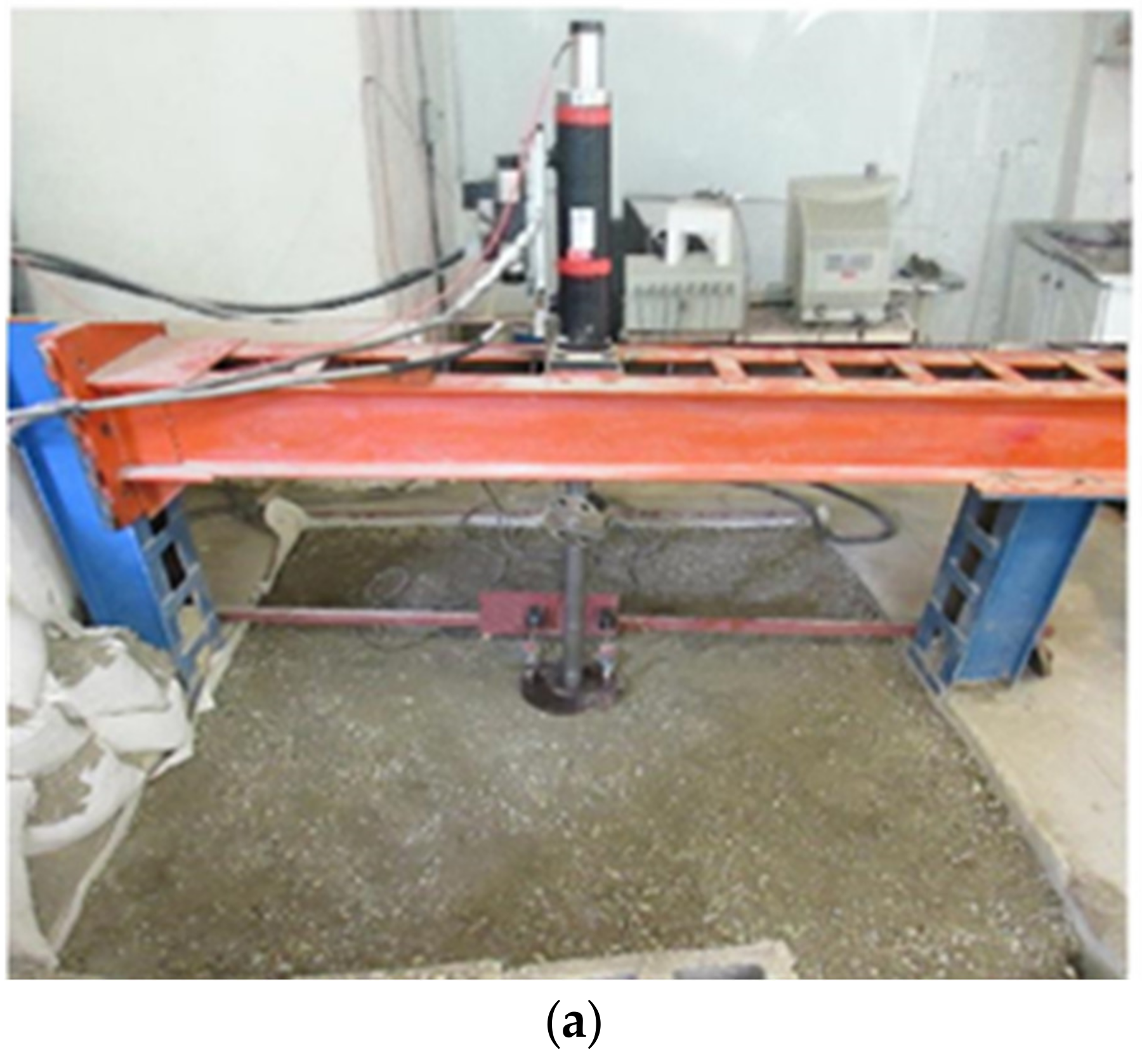
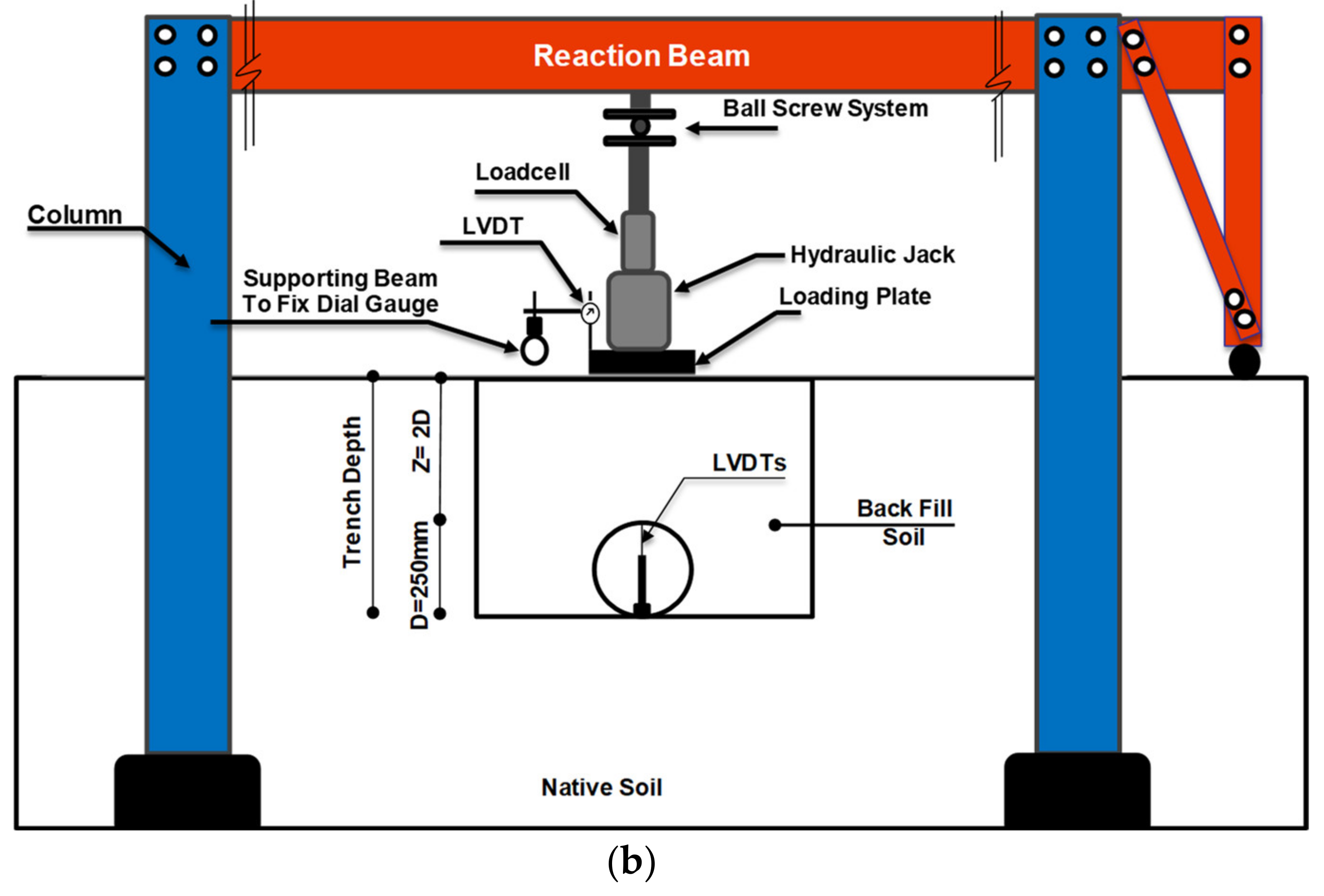
2.1.4. Testing Trench

A full-scale model containing the pipe and EPS block was prepared in a test trench with dimensions of 2000 × 1400 mm and depth of 800 mm. The trench width was selected to meet the recommendations of AASHTO (2010) [24] and ASTM D2321-08 [20]. ASTM D2321-08 [20] recommend the minimum trench width as 1.25D + 300 mm, and AASHTO [24] suggests the maximum value between 1.5D + 305 mm and D + 406 mm (where D is the pipe diameter in mm) for the minimum trench width. The maximum burial depth of the pipe was two times the pipe’s diameter (2D = 500 mm), a depth that is common in fieldwork.

2.1.5. Data Measurement System

A data measurement system was developed to automatically read and record the applied load, loading plate settlement, and pipe deformation. An S-shaped load cell, with an accuracy of ±0.01% and a full-scale capacity of 100 kN, was placed between the hydraulic jack and loading plate to precisely measure the applied repeated load. Two linear variable differential transducers (LVDTs) with an accuracy of 0.01% of the full range (100 mm) were attached to opposite edges of the loading plate to measure the average settlement of the loading plate during loading. Based on the previous experience of the authors and other researchers, the maximum deformation of the crown is correspondent to the maximum pipe diametric deformation, and the pipe invert is free of deformation [25,26]. Thus, to measure the maximum pipe diameter deformation during the test, one LVDT with an accuracy of 0.01% of the full range (75 mm) was installed inside the pipe and under its crown and loading center. (Figure 2).

2.2. Test Preparation and Procedure

In order to compact the backfill layers over the pipe, a walk-behind vibrating plate compactor, 450 mm in width, was used. In all tests, the unreinforced soil layers with an optimum moisture content of 5% and wet unit weight of 19.72 kN/m3 were prepared and compacted to a thickness of 50 mm (first pass of compactor) and then 75 mm (second pass). When the backfill was complete, the loading plate with 250 mm diameter (B= 250 mm equals to pipe diameter) was set exactly in the center of the backfill and two LVDTs were installed to record the settlement at the loaded surface. In order to simulate the loads imposed by traffic, a load replicating a heavy vehicle half-axle (40 kN), such as that found on a typical heavy trailer (mean tire pressure 792 kPa), as recommended by Brito et al., 2009 [27] was exerted over a rigid plate with a diameter of 250 mm placed at the center of the trench (Figure 3).

2.3. Experimental Results

Due to the ultra-lightweight of the EPS blocks and their compressibility, attenuation of the exerted loads and arching phenomena may occur in the trench. Arching could cause a reduction of the exerted stress on the buried pipe and create a better situation for pipe protection. Figure 4 shows the maximum pipe crown displacement and soil surface settlement under the imposed load (applied stress). As shown in the figures, by employing the EPS block in the trench of the buried pipe, the maximum pipe crown displacement (the maximum pipe diametric deformation) of the pipe has a 16.7% reduction. This phenomenon supports the compressible inclusion of the EPS block. Therefore, the settlement of the loading surface showed an increase that is an indication of the compressible inclusion of the EPS block. These two experimental analyses were used as a robust source for the numerical analyses which will be discussed below.

3. Numerical Analysis

Diverse numerical methods are available for exploring behavior and response in engineering applications. The finite element method (FEM) has become one of the most frequently used methods for solving versatile equations [28]. ABAQUS software was selected for our analyses [29,30]. ABAQUS has practical capabilities including versatile mesh generation techniques, loading configurations, and material behaviors for use in geotechnical applications. In this study, material properties and dimensions of models were derived from real experimental tests that were done for incipient analyses and verifications. Meanwhile, some material properties mentioned by other researchers are of practical use for broadening our research. With this in mind, we compare our results with them to ensure their precision.

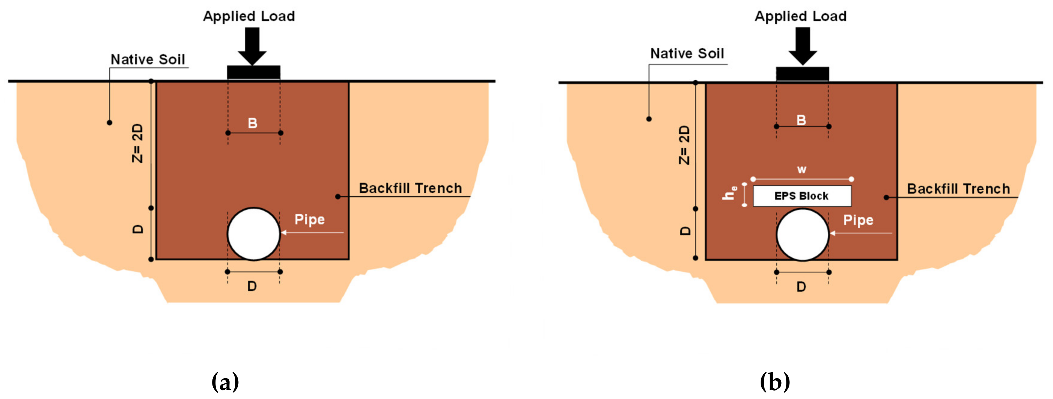
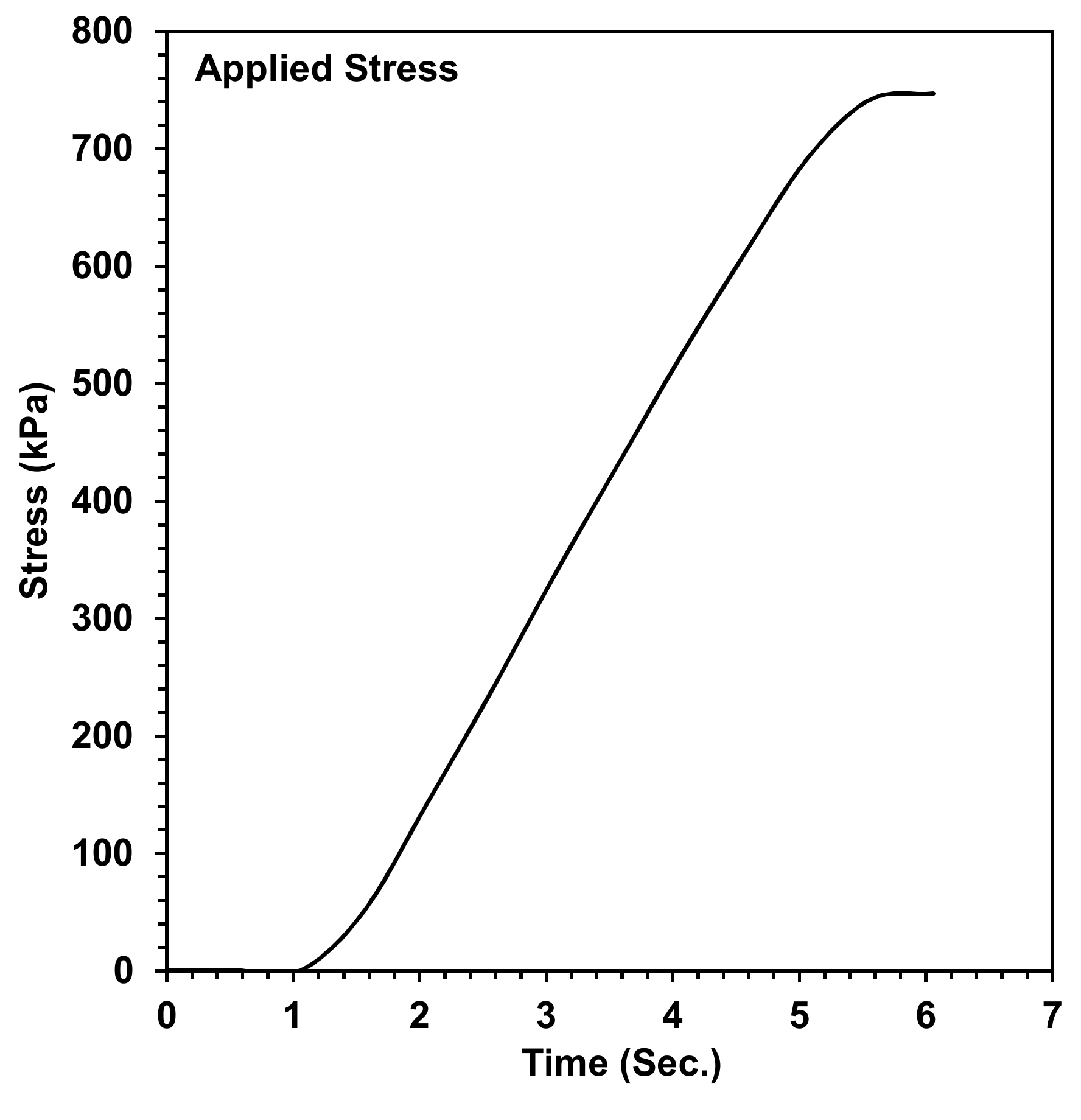
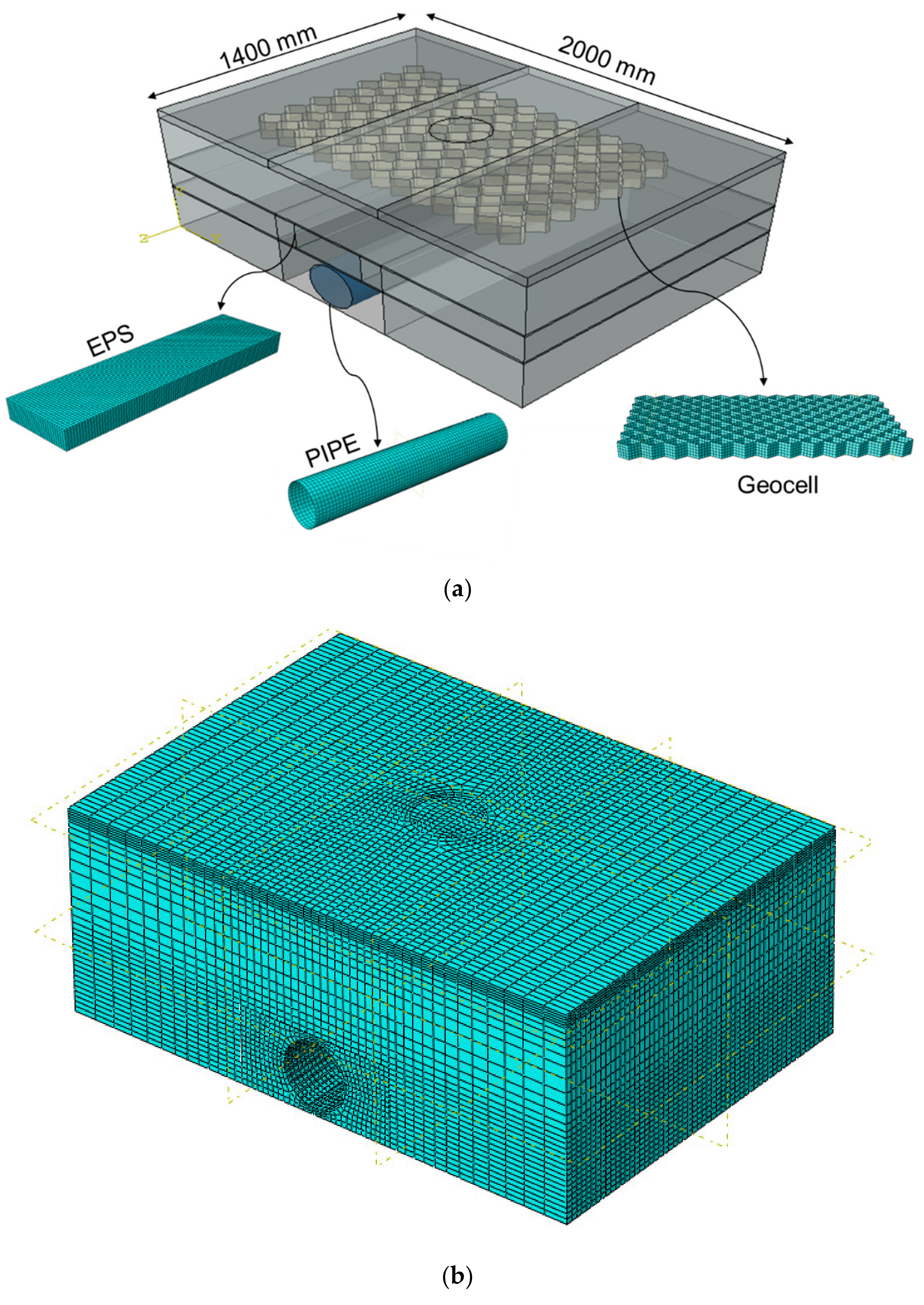
3.1. Loading and Geometry

The numerical models have the same dimensions as the physical model. The experimental load was imposed numerically on the soil surface with a diameter of 250 mm representing the area of vehicle tires on the trench surface. The placement of geofoam is modeled according to the predefined tests and proposed numerical analyses, and the dimensions of the trench are sufficient for modeling a large-scale pipe that is exposed to real loading from the surface. In the numerical model, the sides were immovable in the horizontal direction and set free in the perpendicular direction. Figure 5 shows the typical geometry parameters of the model and the full-scale 3D model generated by the software.

3.2. Material Models and Properties

3.2.1. Soil, Geocell, and Pipe
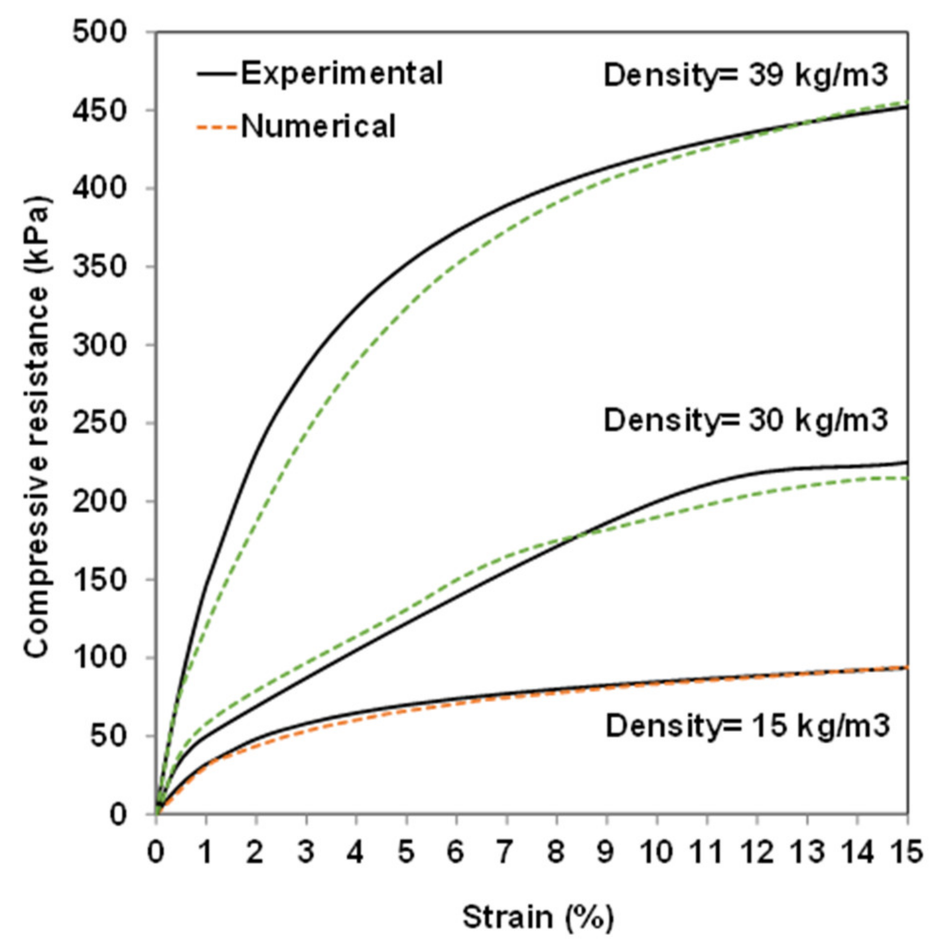
A linear Drucker–Pager model available in ABAQUS was used to simulate the elastic and plastic behavior of the soil. This model has more realistic results and the capability to see the hardening behavior, hence we employed it for our analyses [31]. The geocell and the pipe are considered elastic materials. Table 1 shows the values of the parameters for the soil, geocell, and pipe. The geocell and pipe parameters are as given by the manufacturer. Meanwhile, the soil parameters used were in close alignment with other research [14].

3.2.2. EPS Geofoam

In the experimental analyses, only EPS geofoam block (density 30 kg/m3) was used over the buried pipe. It would be useful to widen our research by investigating other densities using a numerical approach. Bartlett et al. (2015) presented a complex constitutive model that was derived from experimental analyses for modeling EPS geofoam block behavior [17]. The proposed model can follow the three steps of EPS block behavior (initial elastic strain, relatively large plastic strain, and strain-hardening scenarios). The model and its parameters related to the experimental analyses of compression can be given as:
ε σ = a × ε 3 + b × ε 2 + c × ε + d
where σ is the applied uniaxial compressive stress (kPa) and ϵ is the axial strain in %. The advantage of this model is that it can simulate the whole range of EPS behaviors. Table 2 presents the fitted parameters for various densities of EPS.
The behavior of EPS materials can be obtained with the required densities from these parameters. Subsequently, the elastic-plastic behavior can be converted from the nominal test data into its true values and then the total strain values decomposed into elastic and plastic strain components to allow for direct data input into ABAQUS. This approach uses the algorithm mentioned in another research paper [32]. Unconfined uniaxial compressive testing (ASTM D 1621-00 [33]) was performed on 200 mm cubic specimens of EPS with a density of 30 kg/m3 and direct stress-strain; the response was used in the numerical analysis. It is worth mentioning that the elastic limit and compressive strength of EPS geofoam are defined as the stress at 1% and 10% strain, respectively [34]. Figure 6 shows the verification of experimental and numerical analyses for employed EPS blocks. As is clear, the proposed model is capable of monitoring the EPS blocks’ behaviors with high accuracy.

3.3. FE Mesh Details
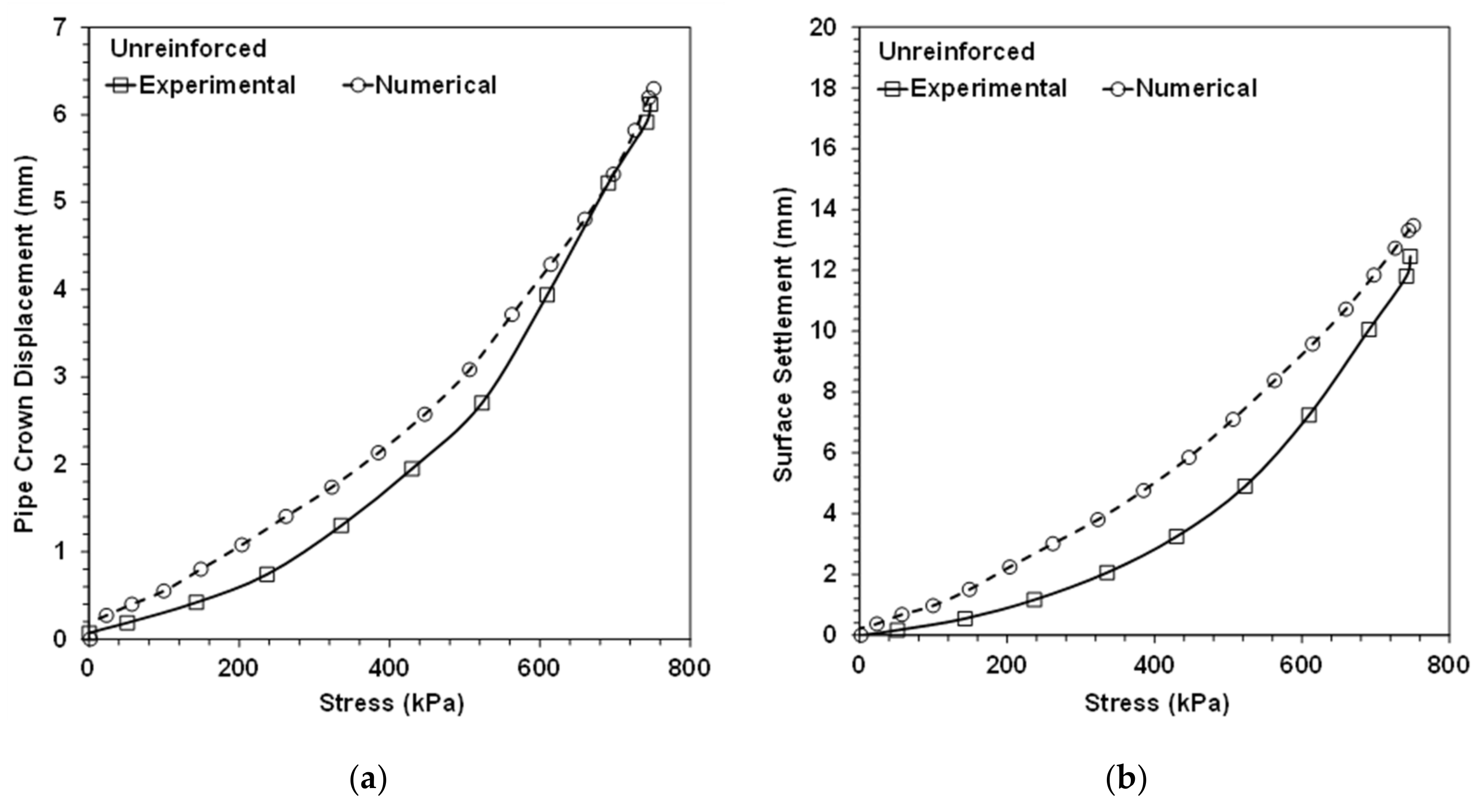
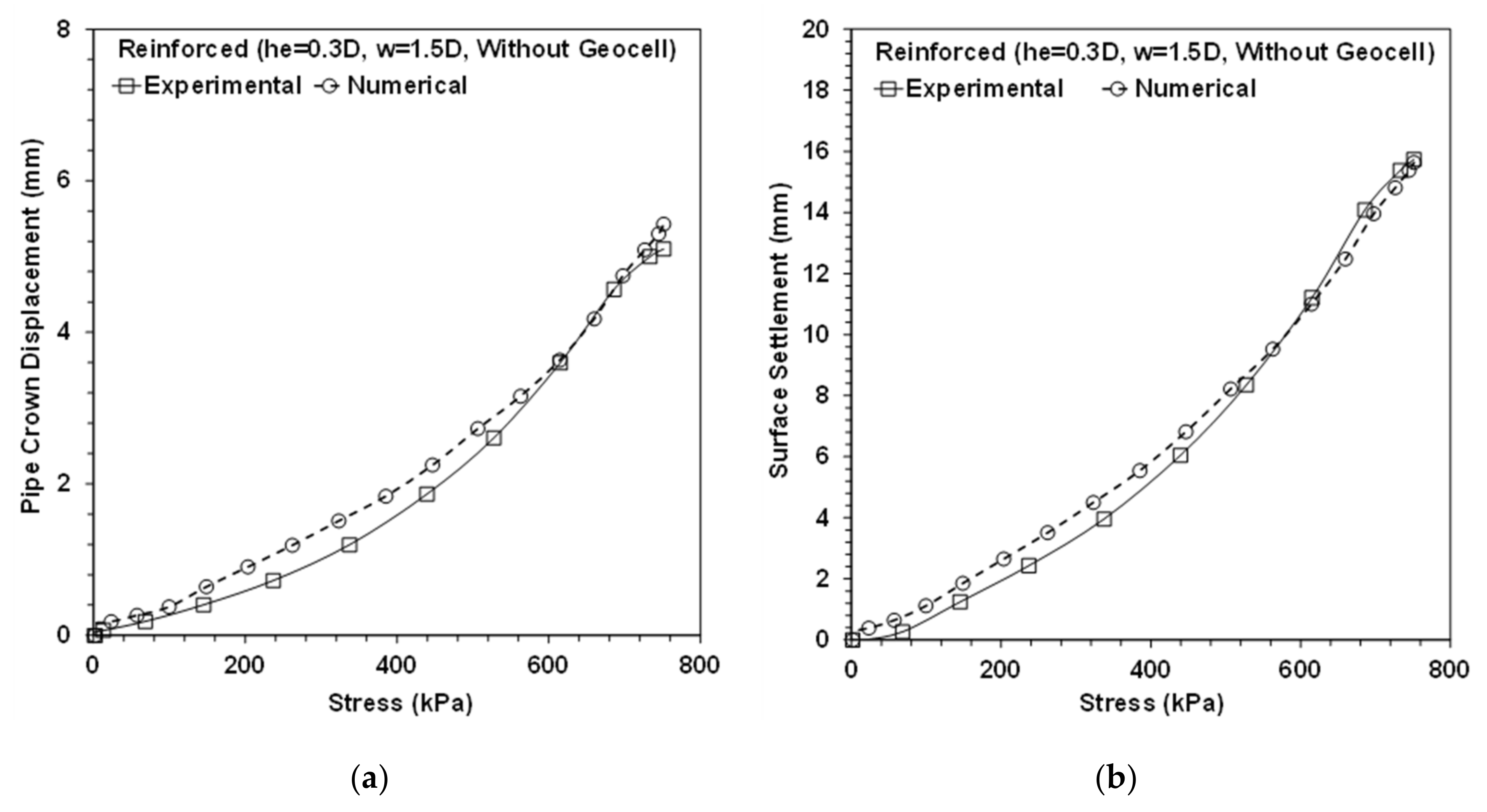
Precise 3D models representing the true experimental conditions and dimensions were created and meshed as shown in Figure 7. A total of 94,928 hexahedral linear elements with reduced integration formulation (C3D8R) were used for the soil. The elements around the surface loading and pipe were meshed with high density to enable the computation of extensive deformations and to guarantee more accurate results. Since the maximum settlement occurs near the trench surface, this strategy is implemented near the trench surface to increase the accuracy of the results. In addition, the geocell was modeled with a total of 8160 linear membrane elements (M3D4R). Since embedded interaction provides a situation in which the host region and embedded structure act as a single unit, embedded interaction was employed between the soil and the geocell. The pipe was modeled with a total of 2730 elements with linear four-node shell elements (S4R), and EPS blocks, like the soil, were modeled by hexahedral linear elements with reduced integration formulation (C3D8R). The frictional coefficient between the EPS block with trench soils was considered to be 0.6 [35]. The friction angle value between the pipe and the soil was set to half of the peak frictional angle of the soil [36]. In order to simulate the real situation, the boundary conditions for both experimental study and numerical study were modeled based on a continuous pipeline which needs fixed horizontal conditions.

3.4. Validation

In this section, a basis of numerical analyses by verification of two experimental analyses is presented. The explicit solver was selected for scrutinizing the system and obtaining the results. The explicit method provides accurate results if the parameters are chosen exactly and if a practical system with high calculation ability (i.e., able to solve problems in a sensible running time) is employed. Gravity was implemented, as well as surface loading, to give more accurate results. Figure 8 shows the verification of the experimental test in which the combined behavior of the soil and the pipe against the applied stress was examined. The results of the numerical analysis show a slight discrepancy from the experimental results. Because of this difference, the behavior of the EPS block (density 30 kg/m3) was investigated. The results of this analysis show a similar trend to the experimental results (Figure 9). These results show that the numerical procedure, parameters, and behavior of the materials are reliable. It is clear that the mentioned discrepancy is comparable based on experimental and numerical results considering inhomogeneous materials and error in experimental analyses derived from measuring instruments and operator errors. For validation, a geocell with the characteristics given in Table 1 was overlaid at the optimum depth (u= 50 mm) and width (1400 mm) advised by Moghaddas Tafreshi and Dawson, 2010 [37], and embedded in the solo soil trench that was lacking a pipe and other reinforcing materials and had the same dimensions as in the experimental tests. In the geocell reinforced test, the geocell pocket sizes were 110 × 110 mm2 with a height (hg) of 100 mm. The imposed load over the trench without any reinforcing element and pipe had the same values as utilized in all the numerical and experimental analyses. The trend of this verification is similar to that obtained by other researchers [12] when the implemented geocell and soil have the same stiffness (Figure 10).

4. Results and Discussion

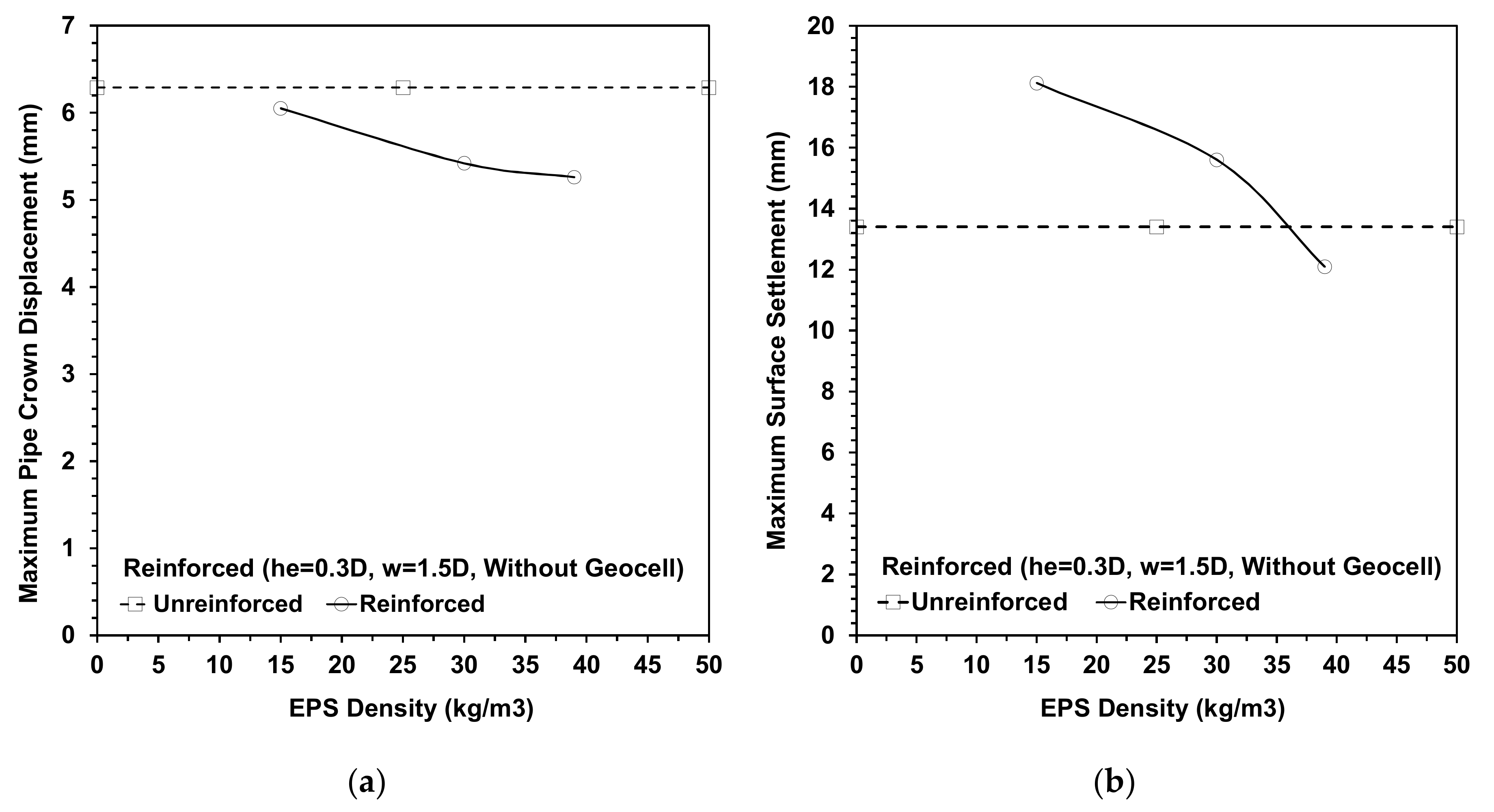
4.1. Effect of EPS Density

EPS blocks with a thickness of 0.3D and 1.5D width were used in three densities of 15, 30, and 39 kg/m3. As the density of EPS blocks increases, the area under the stress-strain diagram increases, thus an increase in the block’s ability to absorb energy would be expected. Figure 11 shows the variation of the maximum pipe crown displacement and surface settlement with the load for different densities of EPS block. Figure 11 shows that as the density of the EPS block increases, the pipe crown displacement and surface settlement decrease. For example, with a decrease in the density of the EPS block from 39 to 15 kg/m3, the maximum pipe crown displacement was increased by 15%. This can be attributed to the lack of sufficient resistance with the low density of the EPS block (15 kg/m3), and little absorption in the EPS block, resulting in a large stress transferred onto the pipe.

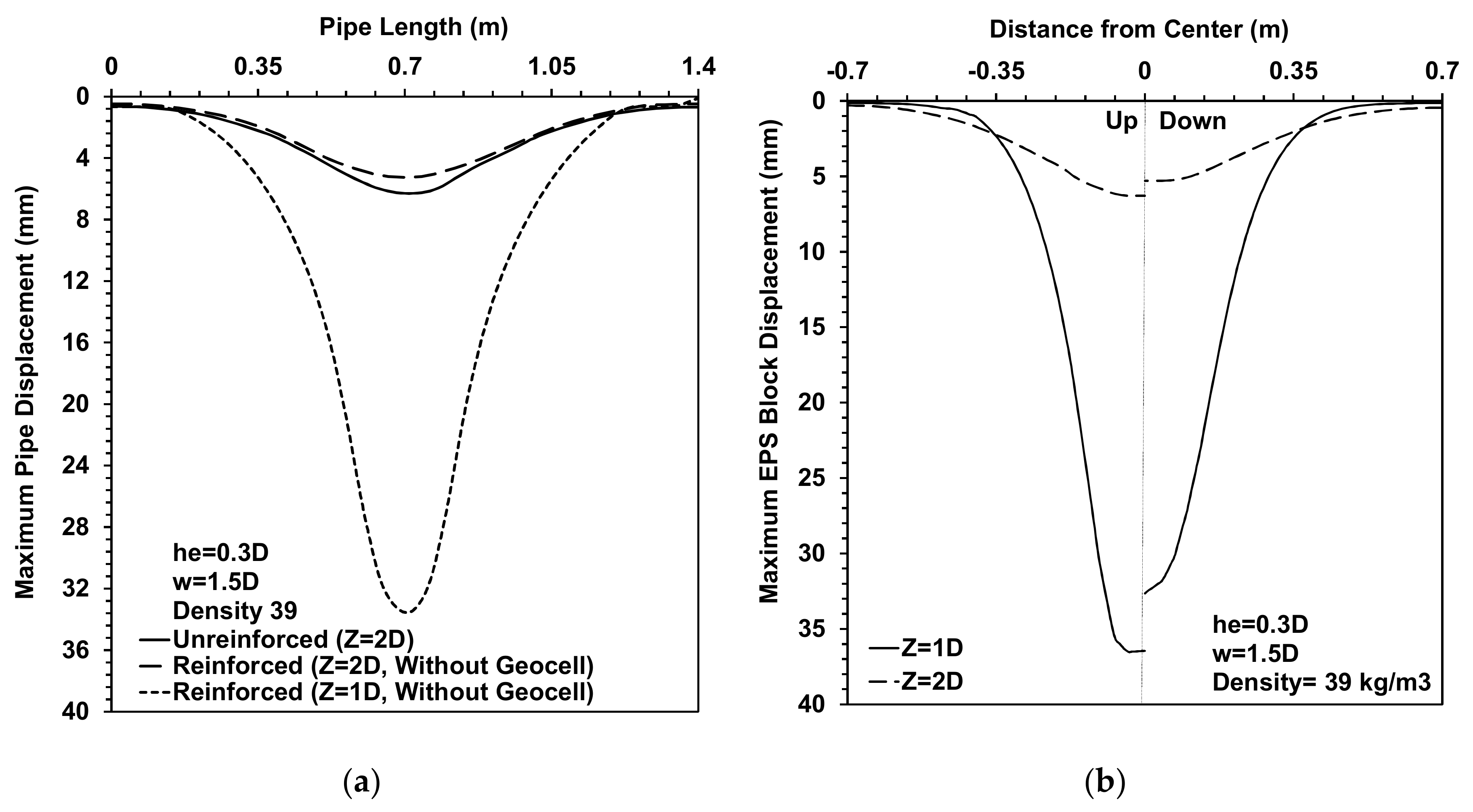
4.2. Effect of Embedding Depth

One of the pivotal points in implementing EPS in a project is the design of the stress over the embedded EPS geofoam blocks. Many regulations suggest using a concrete slab over the buried EPS blocks [38,39,40]. With this in mind, we implemented the best result of our analyses with the pipe burial depth of D rather than 2D (he = 0.3D, w = 1.5D, and density 39). Figure 12a shows the maximum crown displacement values over the pipe length in which the maximum displacement increased from 5.26 mm to about 33 mm by decreasing the burial depth to 1D. In Figure 12b, the maximum deformations in the top and bottom faces of EPS blocks are over their lengths, and the figure shows the EPS block faces deformation increased on average by 28 mm by decreasing the depth of the pipe from 2D to 1D. For clarification, it should be mentioned that by decreasing the depth to 1D, the pipe in the unreinforced condition fails under the huge deformation. When EPS blocks are implemented over buried pipes, the maximum soil surface settlement increases from 12.09 to 38 mm by decreasing the burial depth from 2D to 1D. From these results, it is clear that the depth of the pipelines and EPS blocks have significant effects on complex pipe systems.

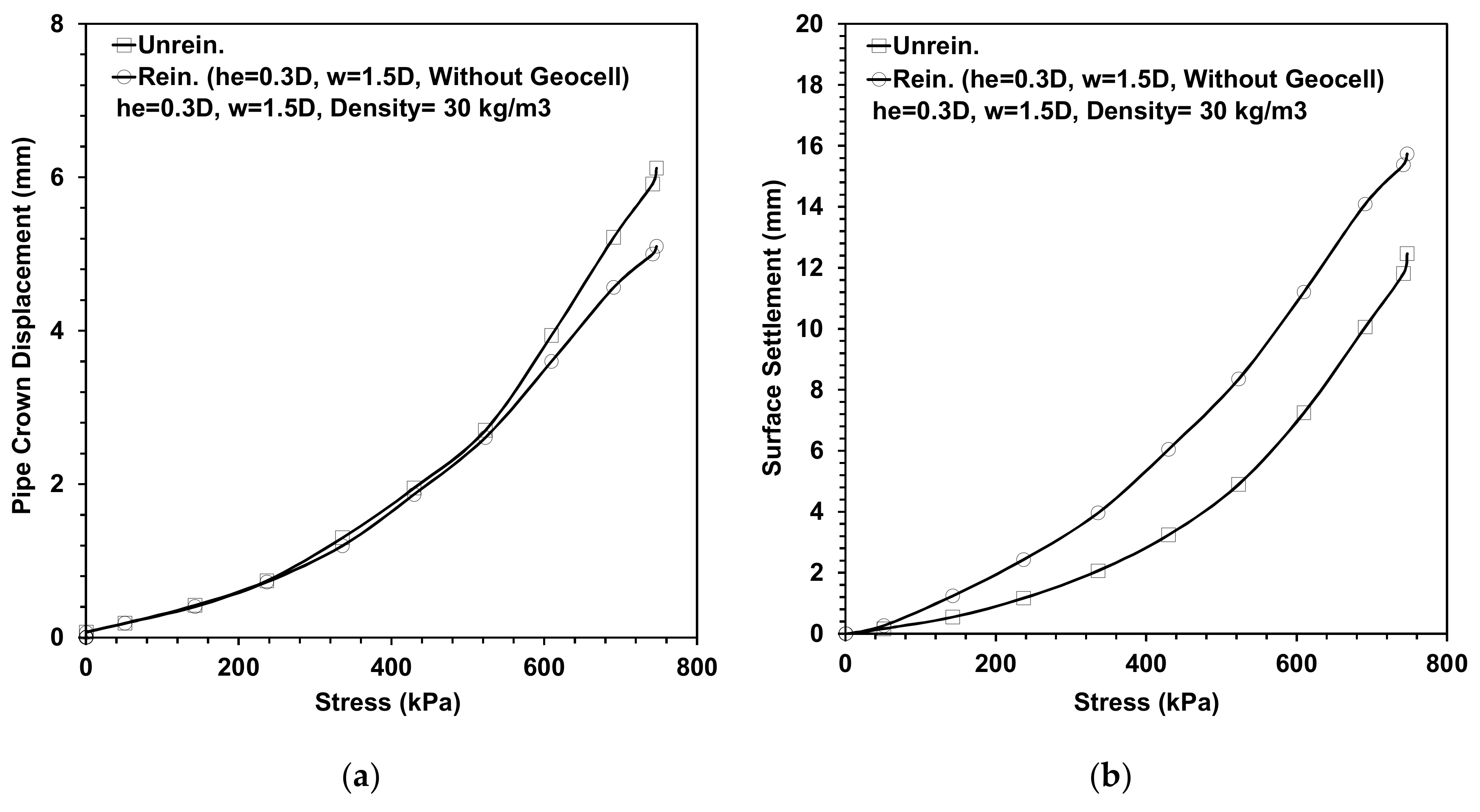
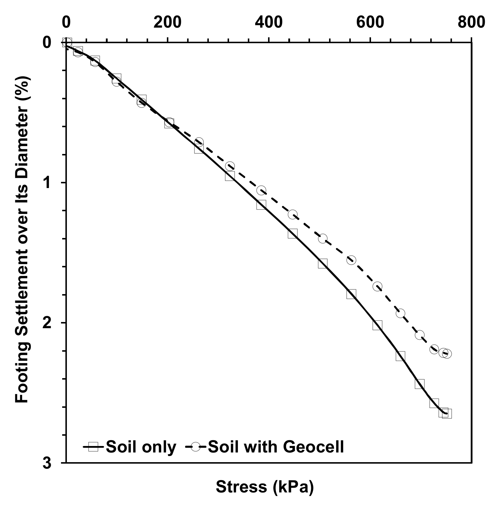
4.3. Effect of Geocell

In this section, the effect of the geocell layer in improving the behavior of the buried pipe is described. The geocell layer was used with an EPS geofoam block (39 kg/m3) with a width of 1.5D, a thickness of 0.3D, and a density of 39 kg/m3. The results of this analysis illustrate the role of a geocell layer in improving the behavior of buried pipes reinforced by a single geofoam layer.
Figure 13a shows the effect of the geocell layer on the behavior of the pipes reinforced with a geofoam block and a geocell layer along the pipe length. We know that by using a geofoam block the maximum pipe crown displacement experiences a reduction of 17%. This amount is 39.5% when an EPS block is used with a geocell layer. This decrease reflects the efficiency of a geocell layer in improving the behavior of buried pipes. Figure 13b shows the maximum deformations in the top and bottom faces of the EPS blocks along their lengths. This figure shows that by implementing a geocell layer over the embedded EPS blocks, the maximum settlement values decreased by an average about 26%, and the embedded EPS block is better able to ameliorate the pipe behavior in this situation.
Figure 14 shows the level of surface settlement against applied stress in the presence of a single geofoam block and a geofoam block with a geocell layer. In this case, the geocell layer reduces the maximum loading settlement by 29%. This provides further evidence that the geocell reinforced system reduces the pipe deformation and decreases soil surface settlement.

5. Conclusions

Buried pipes are a key part of the infrastructure of every society, thus, their behavior and the amelioration of adverse behaviors is the subject of much research. Geosynthetic materials have sufficient ability to ameliorate and guarantee the performance of pipes. Over recent years, the use of EPS geofoam material in geotechnical projects has increased, and there is no doubting their astonishing abilities, which include their very small Poisson ratio, low volume density, and predefined characteristics. This paper presents a combination of experimental and numerical analyses to evaluate the behavior of buried pipes under versatile conditions in which an EPS geofoam block is laid over a trench surface covering buried pipes and exposed to specified trench surface loading. The parameters used are the density of EPS blocks, the depth of the buried pipes, and the combination of a geocell layer with EPS blocks. It should be mentioned that the width and thickness of EPS blocks are equal to 1.5 and 0.3 times the pipe diameter. The results indicate:
  • By decreasing the EPS block densities, the pipe crown displacement values increased. With a decrease in the density of EPS block from 39 to 15 kg/m3, the maximum pipe crown displacement showed a 15% increase.
  • By increasing the EPS block density to protect the pipe, the surface loading settlement decreases.
  • The results indicate that a crucial point in the behavior of EPS blocks is the depth of burial from the loading source. The maximum pipe crown displacement increased from 5.26 mm to about 33 mm by decreasing the burial depth from 2D to 1D. However, by decreasing the burial depth of the unreinforced buried pipe to 1D, the embedded pipe failed.
  • When using a geofoam block, the maximum pipe displacement was reduced by 17%. This value rose to 39.5% when the EPS block was combined with a geocell layer.
  • The geocell layer is able to reduce the maximum surface loading settlement, and in the gamut of the analyses, the soil surface settlement decreased by 29%.

Author Contributions

Conceptualization, S.N.M.T.; Data curation, M.A. and N.J.D.; Formal analysis, N.J.D.; Funding acquisition, H.J.; Investigation, M.A. and N.J.D.; Methodology, O.K., M.A. and N.J.D.; Project administration, O.K.; Resources, O.K.; Software, M.A.; Supervision, O.K.; Validation, S.N.M.T.; Writing—review & editing, O.K. All authors have read and agreed to the published version of the manuscript.

Funding

This research was funded by the Ministry of Education of the Czech Republic, grant number LO1502 and The APC was funded by 600 CHF.

Acknowledgments

The present contribution has been prepared under project LO1502 “Development of the Regional Technological Institute” under the auspices of the National Sustainability Program I of the Ministry of Education of the Czech Republic aimed to support research, experimental development and innovation.

Conflicts of Interest

The authors declare no conflict of interest.

References

  1. Elragi, A.F. Selected Engineering Properties and Applications of EPS Geofoam. Ph.D. Thesis, State University of New York, New York, NY, USA, 2000. [Google Scholar]
  2. Anil, Ö.; Erdem, R.T.; Kantar, E. Improving the impact behavior of pipes using geofoam layer for protection. Int. J. Press. Vessel. Pip. 2015, 132, 52–64. [Google Scholar] [CrossRef]
  3. Azizian, M.; Moghaddas Tafreshi, S.N.; Darabi, N.J. Experimental evaluation of an expanded polystyrene (EPS) block-geogrid system to protect buried pipes. Soil Dyn. Earthq. Eng. 2020, 129, 105965. [Google Scholar] [CrossRef]
  4. Beju, Y.; Mandal, J. Combined use of jute geotextile-EPS geofoam to protect flexible buried pipes: Experimental and numerical studies. Int. J. Geosynth. Ground Eng. 2017, 3, 32. [Google Scholar] [CrossRef]
  5. Hegde, A.; Sitharam, T. Experimental and numerical studies on protection of buried pipelines and underground utilities using geocells. Geotext. Geomembr. 2015, 43, 372–381. [Google Scholar] [CrossRef]
  6. Khalaj, O.; Azizian, M.; Moghaddas Tafreshi, S.N.; Mašek, B. Laboratory investigation of buried pipes using geogrid and EPS geofoam block. In Proceedings of the IOP Conference Series: Earth and Environmental Science, World Multidisciplinary Earth Sciences Symposium (WMESS 2017), Prague, Czech Republic, 11–15 September 2017; p. 022002. [Google Scholar]
  7. Khalaj, O.; Darabi, N.J.; Moghaddas Tafreshi, S.N.; Mašek, B. Protection of buried pipe under repeated loading by geocell reinforcement. In Proceedings of the IOP Conference Series: Earth and Environmental Science, World Multidisciplinary Earth Sciences Symposium (WMESS 2017), Prague, Czech Republic, 11–15 September 2017; p. 022030. [Google Scholar]
  8. Khalaj, O.; Darabi, N.J.; Moghaddas Tafreshi, S.N.; Jeníček, Š. Damping Ratio of Foundation Bed with Multi-layered Rubber-Soil Mixtures. In Proceedings of the IOP Conference Series: Earth and Environmental Science, Prague, Czech Republic, 3–7 September 2018; p. 012008. [Google Scholar]
  9. Khalaj, O.; Davarifard, S.; Moghaddas Tafreshi, S.N.; Mašek, B. Cyclic Response of Footing with Embedment Depth on Multi-Layered Geocell-Reinforced Bed. In Proceedings of the IOP Conference Series: Earth and Environmental Science, World Multidisciplinary Earth Sciences Symposium (WMESS 2016), Prague, Czech Republic, 5–9 September 2016; p. 022015. [Google Scholar]
  10. Khalaj, O.; Siabil, S.M.A.G.; Moghaddas Tafreshi, S.N.; Jirkova, H. Performance Evaluation of Pavements Constructed on EPS Geofoam Backfill Using Repeated Plate Load. In Proceedings of the IOP Conference Series: Earth and Environmental Science, Prague, Czech Republic, 3–7 September 2018; p. 012007. [Google Scholar]
  11. Khalaj, O.; Siabil, S.M.A.G.; Moghaddas Tafreshi, S.N.; Kepka, M.; Kavalir, T.; Křížek, M.; Jeníček, Š. The experimental investigation of behaviour of expanded polystyrene (EPS). In Proceedings of the IOP Conference Series: Earth and Environmental Science, Pilsen, Czech Republic, 10–13 September 2019. [Google Scholar]
  12. Khalaj, O.; Moghaddas Tafreshi, S.N.; Masek, B.; Dawson, A.R. Improvement of pavement foundation response with multi-layers of geocell reinforcement: Cyclic plate load test. Geomech. Eng. 2015, 9, 373–395. [Google Scholar] [CrossRef]
  13. Kim, H.; Choi, B.; Kim, J. Reduction of earth pressure on buried pipes by EPS geofoam inclusions. Geotech. Test. J. 2010, 33, 304–313. [Google Scholar]
  14. Moghaddas Tafreshi, S.N.; Joz Darabi, N.; Dawson, A.R.; Azizian, M. Experimental Evaluation of Geocell and EPS Geofoam as Means of Protecting Pipes at the Bottom of Repeatedly Loaded Trenches. Int. J. Geomech. 2020, 20, 04020023. [Google Scholar] [CrossRef]
  15. Witthoeft, A.; Kim, H. Numerical investigation of earth pressure reduction on buried pipes using EPS geofoam compressible inclusions. Geosynth. Int. 2016, 23, 287–300. [Google Scholar] [CrossRef]
  16. Maleska, T.; Nowacka, J.; Beben, D. Application of EPS Geofoam to a Soil–Steel Bridge to Reduce Seismic Excitations. Geosciences 2019, 9, 448. [Google Scholar] [CrossRef] [Green Version]
  17. Bartlett, S.F.; Lingwall, B.N.; Vaslestad, J. Methods of protecting buried pipelines and culverts in transportation infrastructure using EPS geofoam. Geotext. Geomembr. 2015, 43, 450–461. [Google Scholar] [CrossRef]
  18. Rasouli, H.; Fatahi, B. Geofoam blocks to protect buried pipelines subjected to strike-slip fault rupture. Geotext. Geomembr. 2019, 48, 257–274. [Google Scholar] [CrossRef]
  19. ASTM D2487-11. Standard Practice for Classification of Soils for Engineering Purposes (Unified Soil Classification System); ASTM International: West Conshohocken, PA, USA, 2011.
  20. ASTM D2321-08. Standard Practice for Underground Installation of Thermoplastic Pipe for Sewers and Other Gravity-Flow Applications; ASTM International: West Conshohocken, PA, USA, 2008.
  21. ASTM D1557-12. Standard Test Methods for Laboratory Compaction Characteristics of Soil Using Modified Effort.; ASTM International: West Conshohocken, PA, USA, 2012.
  22. Moghaddas Tafreshi, S.N.; Darabi, N.J.; Dawson, A.R. Combining EPS geofoam with geocell to reduce buried pipe loads and trench surface rutting. Geotext. Geomembr. 2020, 48, 400–418. [Google Scholar] [CrossRef]
  23. BSI (British Standard Institute). Thermoplastics Ancillary Fittings of Nominal Sizes 110 and 160 for below Ground Gravity Drainage and Sewerage; BS 4660; BSI: London, UK, 2000. [Google Scholar]
  24. American Association of State Highway and Transportation Officials (AASHTO). LRFD Bridge Design Specifications; AASHTO: Washington, DC, USA, 2010. [Google Scholar]
  25. Talesnick, M.; Xia, H.-W.; Moore, I. Earth pressure measurements on buried HDPE pipe. Geotechnique 2011, 61, 721–732. [Google Scholar] [CrossRef] [Green Version]
  26. Moghaddas Tafreshi, S.N.; Khalaj, O. Laboratory tests of small-diameter HDPE pipes buried in reinforced sand under repeated-load. Geotext. Geomembr. 2008, 26, 145–163. [Google Scholar] [CrossRef]
  27. Brito, L.; Dawson, A.R.; Kolisoja, P.J. Analytical evaluation of unbound granular layers in regard to permanent deformation. In Proceedings of the 8th International on the Bearing Capacity of Roads, Railways, and Airfields (BCR2A’09), Champaign, IL, USA, 29 June–2 July 2009; pp. 187–196. [Google Scholar]
  28. Dhatt, G.; Lefrançois, E.; Touzot, G. Finite Element Method; John Wiley & Sons: Hoboken, NJ, USA, 2012. [Google Scholar]
  29. Helwany, S. Applied Soil Mechanics with ABAQUS Applications; John Wiley & Sons: Hoboken, NJ, USA, 2007. [Google Scholar]
  30. Manual, A.U. Version 6.10; ABAQUS Inc.: Providence, RI, USA, 2010. [Google Scholar]
  31. Aksoy, C.O.; Safak, S. Comparing Mohr Coulomb and Drucker Prager function in three dimensional analysis on rock. In Proceedings of the Geophysical Research Abstracts, EGU General Assembly, Vienna, Austria, 2–7 May 2010; Volume 12, p. EGU2010-14779-1. [Google Scholar]
  32. Meguid, M.; Hussein, M. A numerical procedure for the assessment of contact pressures on buried structures overlain by EPS geofoam inclusion. Int. J. Geosynth. Ground Eng. 2017, 3, 2. [Google Scholar] [CrossRef]
  33. American Society for Testing and Materials (ASTM). Standard Test Method for Compressive Properties of Rigid Cellular Plastics; ASTM D1621; ASTM: West Conshohocken, PA, USA, 2010. [Google Scholar]
  34. Horvath, J. Expanded polystyrene (EPS) geofoam: An introduction to material behavior. Geotext. Geomembr. 1994, 13, 263–280. [Google Scholar] [CrossRef]
  35. Xenaki, V.; Athanasopoulos, G. Experimental investigation of the interaction mechanism at the EPS geofoam-sand interface by direct shear testing. Geosynth. Int. 2001, 8, 471–499. [Google Scholar] [CrossRef] [Green Version]
  36. Yimsiri, S.; Soga, K.; Yoshizaki, K.; Dasari, G.; O’Rourke, T. Lateral and upward soil-pipeline interactions in sand for deep embedment conditions. J. Geotech. Geoenviron. Eng. 2004, 130, 830–842. [Google Scholar] [CrossRef]
  37. Moghaddas Tafreshi, S.N.; Dawson, A.R. Comparison of bearing capacity of a strip footing supported on sand reinforced with 3D and with planar geotextile. Geotextiles Geomembranes 2010, 28, 72–84. [Google Scholar] [CrossRef]
  38. Arellano, D.; Stark, T.D.; Horvath, J.S.; Leshchinsky, D. Guidelines for Geofoam Applications in Slope Stability Projects; Preliminary Draft Final Report, NCHRP Project No. 24-11; The University of Memphis: Memphis, TN, USA, September 2011. [Google Scholar]
  39. Stark, T.D. Guideline and Recommended Standard for Geofoam Applications in Highway Embankments; Transportation Research Board: Washington, DC, USA, 2004; Volume 529. [Google Scholar]
  40. Stark, T.D.; Arellano, D.; Horvath, J.S.; Leshchinsky, D. Geofoam applications in the design and construction of highway embankments. NCHRP Web Doc. 2004, 65, 792. [Google Scholar]
Figure 1. The concept and scheme of experimental analyses: (a) without expanded polystyrene (EPS) block, (b) with EPS block.
Geosciences 10 00251 g001
Figure 2. (a) Photograph of the test installation including a reaction beam, load plate, hydraulic jack, load cell, and linear variable differential transducers (LVDTs); (b) schematic view of the test setup, instrumentation positions, and geometric parameters (unit in millimeters).
Geosciences 10 00251 g002aGeosciences 10 00251 g002b
Figure 3. Graph showing the applied stress.
Geosciences 10 00251 g003
Figure 4. (a) The maximum pipe crown displacement, (b) the maximum soil surface settlement under the imposed load.
Geosciences 10 00251 g004
Figure 5. Typical geometry parameters of the model.
Geosciences 10 00251 g005
Figure 6. Behavior and verification of EPS blocks.
Geosciences 10 00251 g006
Figure 7. (a) Full-scale 3D model and its ingredients, (b) employed mesh in the 3D model.
Geosciences 10 00251 g007
Figure 8. Verification of the experimental test in the unreinforced condition: (a) the maximum pipe crown displacement, (b) the maximum soil surface settlement under the imposed load.
Geosciences 10 00251 g008
Figure 9. Verification of the experimental test in the reinforced condition: (a) the maximum pipe crown displacement, (b) the maximum soil surface settlement under the imposed load.
Geosciences 10 00251 g009
Figure 10. Assessing the role of a geocell layer in ameliorating the surface settlement.
Geosciences 10 00251 g010
Figure 11. Effect of EPS density on behavior of (a) pipe crown displacement, (b) soil surface settlement under the imposed load.
Geosciences 10 00251 g011
Figure 12. The role of embedding depth in (a) the maximum pipe crown displacement, and (b) the maximum EPS-block surfaces’ settlements under the imposed load
Geosciences 10 00251 g012
Figure 13. The role of a geocell layer in (a) the maximum pipe crown displacement, and (b) the maximum EPS-block surfaces’ settlements under the imposed load.
Geosciences 10 00251 g013
Figure 14. The maximum level of surface settlements in the presence of a single geofoam block and geofoam block with a geocell layer.
Geosciences 10 00251 g014
Table 1. Material properties.
MaterialDensity (kg/m3)Young’s Modulus (MPa)Poisson’s RatioFriction Angle Cohesion (kPa)Dilation Angle
Soil2062450.359.86012
Geocell3332000.35---------
Pipe56010000.45---------
Table 2. EPS parameters (Bartlett et al., 2015).
EPS Density (kg/m3)abcd
15−3.5 × 10⁻⁷−8.1 × 1051.06 × 10−22.05 × 10⁻²
39−3.2 × 1071 × 10−51.8 × 10−35 × 10−3

