Stability of Embankments Resting on Foundation Soils with a Weak Layer


Department of Engineering, University of Palermo, 90128 Palermo, Italy
*
Author to whom correspondence should be addressed.
Geosciences 2021, 11(2), 86; https://0-doi-org.brum.beds.ac.uk/10.3390/geosciences11020086
Submission received: 29 December 2020
/
Revised: 8 February 2021
/
Accepted: 11 February 2021
/
Published: 13 February 2021
(This article belongs to the Special Issue Numerical Modeling in Geotechnical Engineering)
Abstract
:The presence of weak layers in geotechnical systems, including soil or rock masses, both natural and man-made, is more frequent than is normally believed. Weak layers can affect both failure mechanisms, in drained and in undrained conditions, as well as in static and seismic conditions, and the safety factor. In the present study, conducted numerically using the finite-element method (FEM) Plaxis 2D code, the influence of a horizontal thin weak layer on stress and strain distribution, on failure mechanisms and on the overall stability of an embankment was evaluated. The results obtained prove that when the weak layer is located at a significant depth from the foundation plane, the failure mechanisms are normally mixtilinear in shape because the shear strains largely develop on the weak layer. As a result, the safety factor highly decreases compared to the same case without a weak layer. Then, in the presence of weak layers, even embankments that, if founded on homogeneous soils, would have very high global safety factors (higher than 2) can become unstable, i.e., the safety factor can become unitary. So particular attention must be paid during detail ground investigations to finding thin weak layers.
1. Introduction
Natural soils and rock masses, as well as earthworks such as backfills, can include minor structural features. The latter can be characterized by very different constitutive features (e.g., mineralogical composition, grain size distribution and index properties) and hydro-mechanical properties (hydraulic conductivity, shear strength and stiffness) from those of the adjoining geomaterials. Minor structural features can have a very small thickness and, for this reason, may pass undetected when usual ground investigations are carried out. With reference to their difficult identification, Terzaghi (1929) [1] termed these features as “minor geologic details”. In his studies, Terzaghi highlighted the great influence of weak strata on the mechanical behaviour of geotechnical systems and their potentially detrimental effects on the safety of earth dams. Subsequent studies have been performed on this topic, e.g., [2,3,4,5,6,7]. Weak layers, in natural soils and rocks, are more widespread than is believed. They include thin shear bands and sliding surfaces brought about by past instability processes, pre-softened zones within homogeneous soil masses, thin syngenetic seams and laminae such as those occurring in varved clays, structural discontinuities, stratified soils, contact surfaces—sometimes slickensided—among successive strata in earth embankments.
According to the definition given by Picarelli 1991 [8] and D’elia et al. 1998 [9], weak layers can be considered as “structural features” that influence geotechnical systems at the macroscale. For example, the influence of weak layers has been experimentally studied in the field of shallow foundations resting on sand both in a 1× g physical model [10] and in centrifuge physical model (50× g) [11]. In the latter studies, the authors pointed out the strong reduction of the ultimate bearing capacity of the footing compared to the case of homogeneous sandy soil foundations. They also highlighted that the failure mechanism is mixtilinear and passes into the weak layer if the depth of the latter is not wide. The depth of the weak layer, which affects the mechanical behaviour of this geotechnical system, depends on both the shear strength of the weak layer and that of the base soil.
In the field of the stability of natural slopes, the existence of weak layers has been invoked to explain many landslide mechanisms, where the sliding surface presents a significant nearly horizontal part [12], or in slopes with very low inclination [13,14]. More recent studies have also treated the stability of slopes including weak layers [15,16,17,18,19,20,21,22,23,24,25]. Weak layers have further been recognized in the stability of other systems, such as in snow avalanches [26,27,28] and submarine landslides [29,30]. With reference to the latter, Locat et al. (2014) [29] defined the weak layer as follows: “a layer (o band) consisting of sediment or rock that has strength potentially or actually sufficiently lower than that of adjacent units (strength contrast) to provide a potential focus for the development of a surface of rupture. Such a layer or a band can follow stratigraphic horizons, but this is not a requirement.” In addition, in natural geomaterials, weak layers can be produced by different processes, such as layering (sedimentological origin), leaching in the flow of water rich in mineral salts (geochemical origin), strain-softening sediments where progressive failure can be reached or, again, the presence of excess of pore water pressures in thin strata of very high hydraulic conductivity within soil mass with low permeability (geotechnical origins). The weak layers of sedimentological origin can be seen as inherited weak layers, while the weak layers of geotechnical or geochemical origins can be seen as induced weak layers.
So far, very few studies [30] have been carried out on the stability of embankment resting on soil foundations with weak layers. In the present study, the authors, inspired by a real case [31], have carried out an extensive numerical investigation on the influence of a weak layer on the failure mechanism and on the stability of an embankment, constituted of a backfill of a compacted coarse granular material and sustained by a reinforced earth wall. For this real case study, field observations carried out after the geotechnical failure pointed out that very thin shallow weak layers, horizontal or slightly inclined in counter-slope, have conditioned the stability of the backfill as well as the failure mechanisms. The main results of a simplified scheme of the real case (Figure 1) are reported and discussed in the paper, with reference to the results of numerical analyses conducted according to the finite-element method (FEM).
2. Position of the Problem
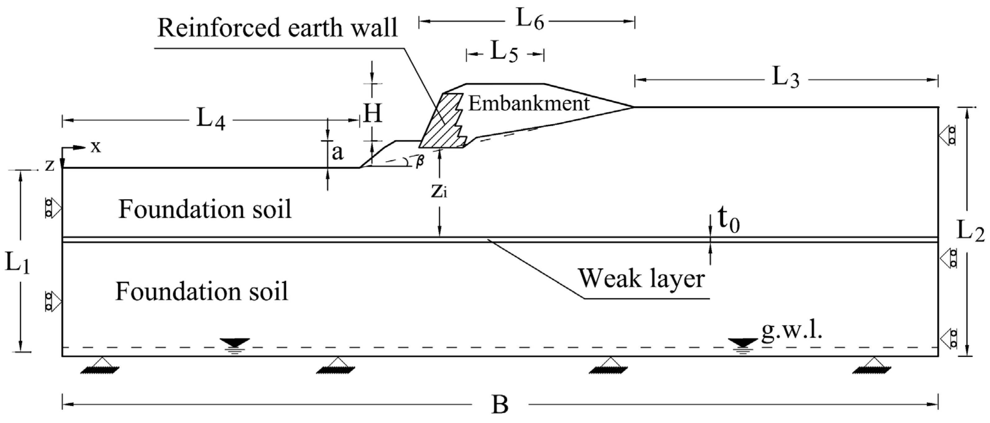
The paper analyses the case of the mechanical behaviour of a compacted granular embankment sustained by a reinforced earth wall. This earthwork was built on foundation soils including a thin horizontal weak layer, characterized by reduced shear strength compared to that of the base soil. The problem is schematized in Figure 1. The weak layer may be considered as representative of a minor structural feature located in the field (e.g., thin shear band, old sliding surface or structural discontinuity), according to the definition in Locat et al. (2014) [29], previously mentioned in the paper.
The embankment rests on a two-dimensional simple slope originally characterized by a mean slope angle of 11° and a height of 9 m. The main dimensions of the modelled scheme are reported in Table 1.
The dimensions were selected by means of preliminary calculations.
In fact, sensitive analyses were conducted to investigate the influence of the dimensions of the model, both in width and in depth, on the analyses. The results showed evidence that the dimensions reported above are adequate for the simulation of the numerical problem.
To fit the embankment with the morphology of the original ground surface, the sides of the embankment were considered to have different slopes: the left side is inclined 66°, while the right side is inclined 15°. This means that the left side is retained by an earth wall including geosynthetic reinforcements, while the rest of the embankment is traditional in type (compacted granular materials with well-graded grain size distribution). The foundation of the embankment is at a depth of 1 m from the modified ground surface. The length of the embankment is significantly greater than its maximum width (32 m). Therefore, the problem can be approached assuming two-dimensional conditions regardless of the presence of the horizontal weak layer, which is located at the depth zi from the foundation plane of the reinforced earth wall (Figure 1) and it is characterized by thickness t0. Considering the values reported in Table 1, the values of zi/H range from 0 to 2.
The main aim of the paper is to provide an insight about the effects of the weak layer on the failure mechanism and on the safety factor of the embankment represented in Figure 1. To do this, a comprehensive numerical analysis program was carried out. The numerical simulations were performed by means of the finite-element (FE) code Plaxis 2D [32]. The two-dimensional scheme reported in Figure 1 was modelled. Plain strain conditions were applied, i.e., the strains take place only in the xz plane (εx ≠ 0; εz ≠ 0), and along the longitudinal axis (out of plane direction) the strain is assumed to be zero (εy = 0). These conditions agree with the geometry of the original slope and the embankment (length significantly larger than the width, [31]). The reference scheme and the boundary conditions of the FE model are shown in Figure 1.
The simple elastic–perfectly plastic Mohr–Coulomb constitutive model with non-associated flow rule was adopted for the modelled geomaterials. The parameters employed in the numerical analyses are listed in Table 2. In this research, zero pore water pressures were considered (dry soils), since in the real case by which the authors were inspired, the depth of the water table detected with the geotechnical investigations was deeper than the weak strata found, as indicated schematically in Figure 1.
However, it is well known that positive pore water pressure, in both hydrostatic and hydrodynamic conditions, has a great influence on the mechanical behaviour of soils and in particular on the stability of slopes, including backfills [33,34,35], and its reduction produces a significant increase of the safety factor of marginally stable slopes [36,37,38]. Water retention behaviour and induced stabilizing suction effects (i.e., negative pore pressure above the water table) were not considered in the constitutive and FE modelling for either compacted or natural soils [39,40]. Pre-peak hardening, post-peak strain-softening, dependence of the constitutive parameters on the stress level and effects linked to progressive failure phenomenon were not considered in the numerical analyses.
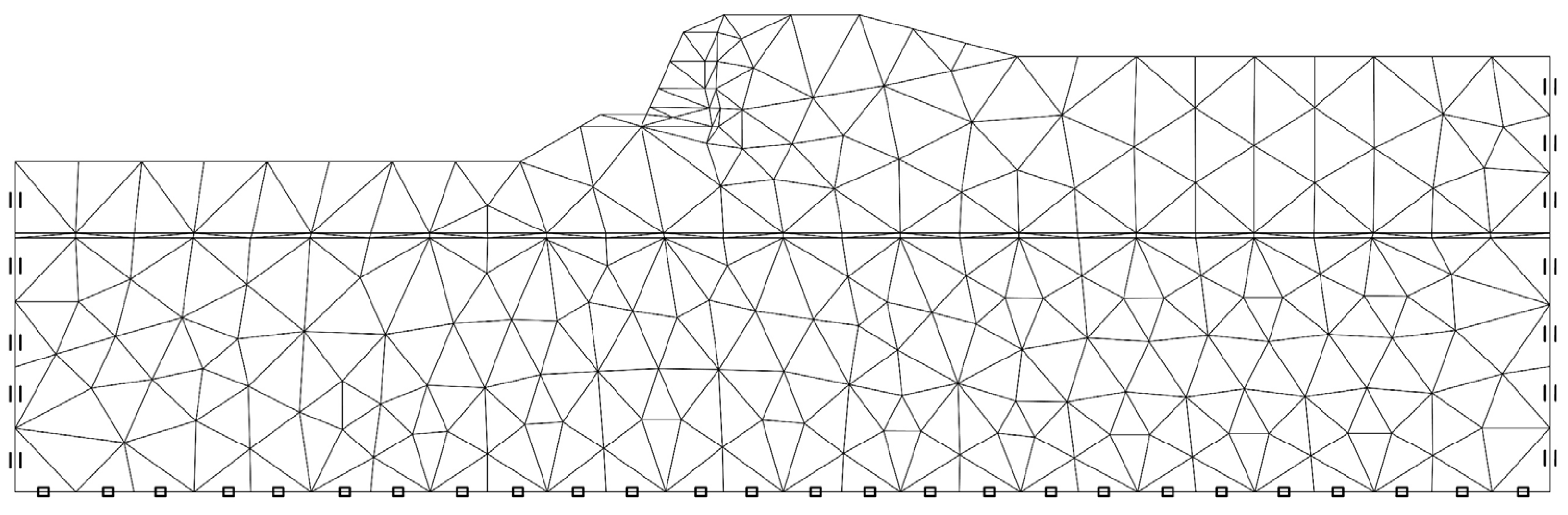
15-Node triangular elements were used to model soils and other volume clusters. According to the two-dimensional finite-element model, only two translation degrees of freedom per node were considered (along x and z directions). Considering the variation of the depth of the weak layer (zi, Figure 1), and considering the variations of the constitutive parameters of materials (Table 1), about 800 FE simulations were carried out. One of the FEM meshes used, the one relating to the case of zi/H = 1.18 is shown in Figure 2.
In the numerical analyses, the gravity loading procedure was applied to generate the initial stress within all the soil bodies [32]. This choice was due to the geometry of the ground surface. After this stage, the phi-c reduction procedure [32] was applied to calculate the safety factor for the considered schemes.
3. Numerical Results
This section presents the results of numerical analyses performed to investigate the effect of the weak layer on mechanical behaviour, and in particular on the deformation mechanisms at failure (Section 3.1) and on the safety factor (Section 3.2), of this complex geotechnical system. Firstly, the case of homogeneous foundation soil was modelled to provide a reference condition for these analyses. In fact, in this case, the shape and the extension of the deformation mechanism reached at failure (i.e., with shear strength parameters reduced according to the phi-c reduction procedure) are not affected by the variation in the soil shear strength parameters considered in the simulations. Obviously, the same cannot be stated when the influence on the safety factor is discussed. Secondly, in the FE model, the weak layer was introduced considering constant thickness t0 = 0.5 m and depth zi ranging from 0 to 17 m. In all analysed cases, the shear strength parameters of the involved soils (foundation soil and weak layer) varied according to the ranges reported in Table 1.
Before presenting the results obtained with the numerical analyses, it is worth clarifying that the analyses are aimed to analyse the global stability of the embankment and, for this reason, any local instabilities due, for example, to insufficient strength or reduced anchor length of reinforcing geomembranes, high slope of the earth wall side and low compaction energy of the embankment body soil are not taken into account [41,42].
3.1. Failure Mechanisms
The failure mechanisms resulting from the numerical analyses can be highlighted considering the distribution of the total displacements as well as the principal directions and the intensities of the total strains resulting from the phi-c reduction calculation stages. Due to the elastic–perfectly plastic constitutive model adopted to model the mechanical behaviour of the involved materials, the exact values of the deformation variables (displacements or strains) reached at failure are not significant. Instead, the spatial variations of these variables are very effective in highlighting the failure mechanisms in the FE models.
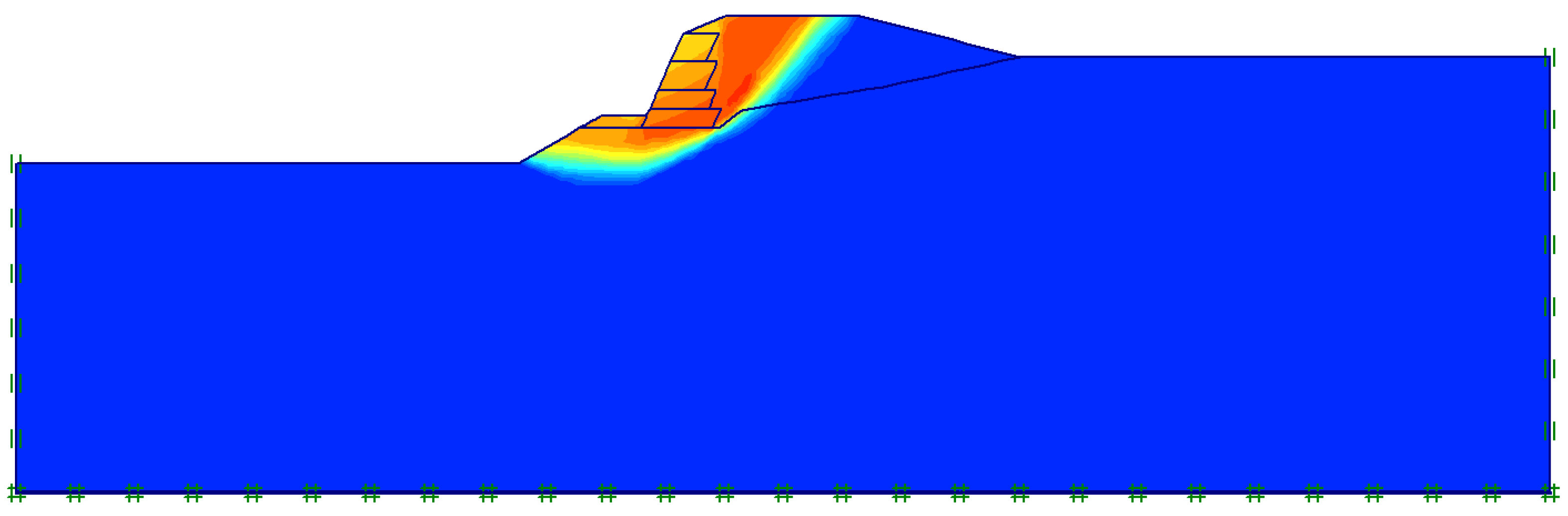
Figure 3 shows the distribution of total displacements that resulted from the numerical analysis carried out considering a homogeneous foundation soil, having c′1 = 10 kPa and φ′1 = 30°, extended down to the bottom of the FE model. This figure clearly shows that, in the case of the homogeneous foundation soil, the failure mechanism is almost circular in type and involves a superficial plasticized soil volume below the foundation of the earth wall and the embankment. Furthermore, from Figure 3, it can be seen that in the backfill a volume very close to that of the Rankine active limit state is affected by significant deformations; that is, it is involved in the failure process. The foundation soils are affected by a failure mechanism, which involves only the soils directly below the base of the reinforced earth wall.
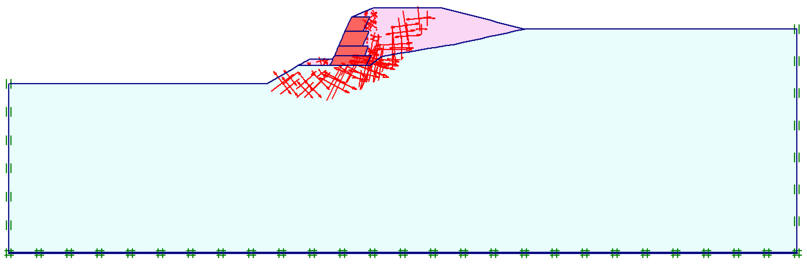
The rotation of the principal directions of strains along the failure mechanism reported in Figure 4 proves that the shear mechanism implies a rotational movement of the soil mass, characterized by a lowering near the crown and a lifting at the toe. However, due to the difference in strength, a secondary shear mechanism can be identified in the area located in the embankment close to the reinforced earth wall.
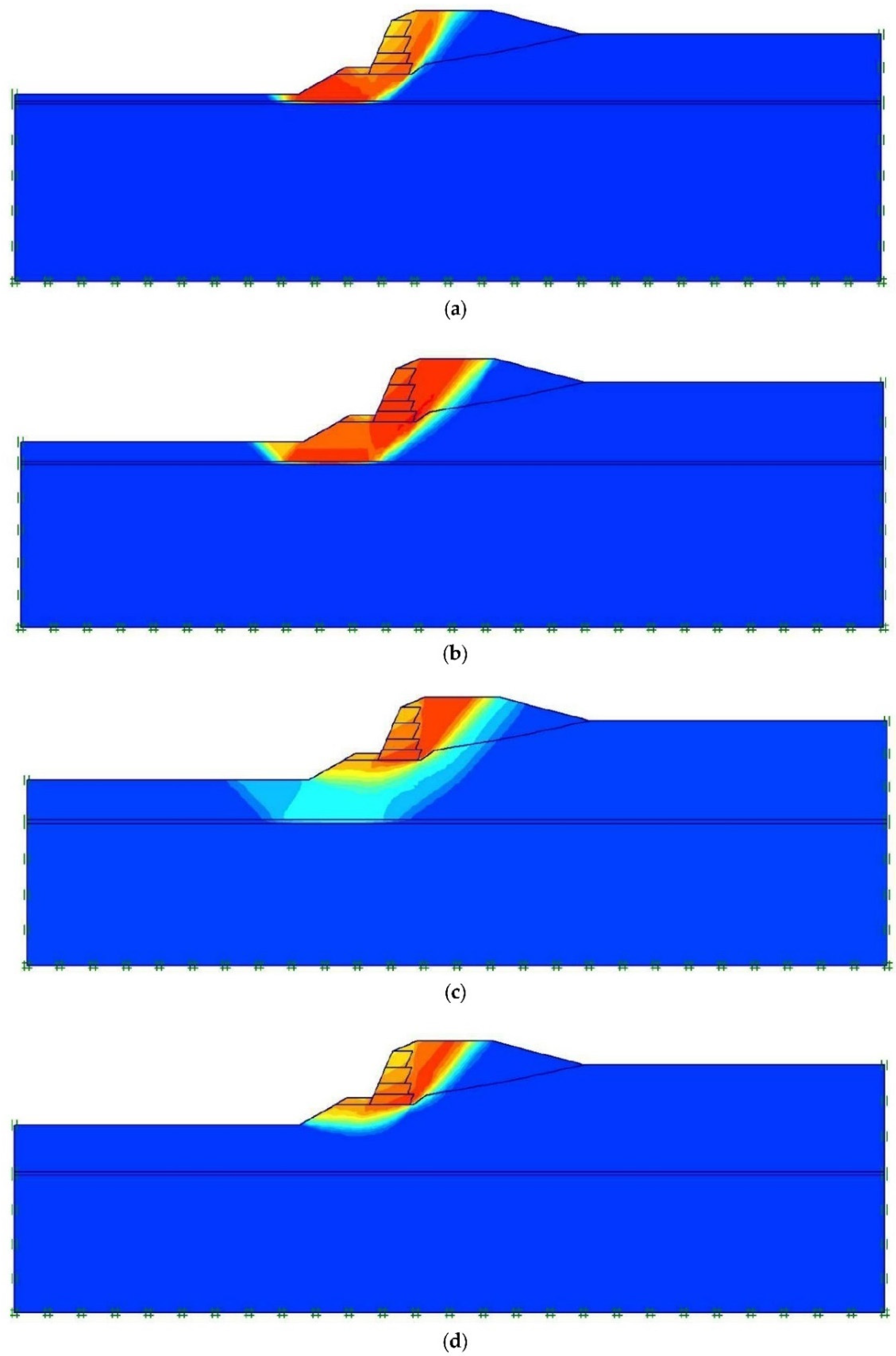
To highlight the influence of the position of the horizontal weak layer in the soil mass on the behaviour of the geotechnical system, Figure 5 shows the distribution of the total displacement resulting from the analyses in which the weak layer is located at depth equal to zi = 4 m (zi/H = 0.47, Figure 5a), zi = 6 m (zi/H = 0.71, Figure 5b) and zi = 9 m (zi/H = 1.06, Figure 5c) and zi = 10 m (zi/H = 1.18, Figure 5d) and its shear strength parameters are c′2 = 0.2 kPa and φ′2 = 10°. In these analyses, the foundation soil has the same mechanical properties considered before for the case of homogeneous soil mass (c′1 = 10 kPa and φ′1 = 30°).
For zi/H = 0.47 (Figure 5a), the failure mechanism is clearly mixtilinear in shape and develops for a long distance in the weak layer. It is very different from the one relative to the case of homogeneous foundation soils (Figure 3).
If the depth of the weak layer does not exceed a maximum value (in this case, about 9 m), it strongly influences both the failure mechanism and the global safety factor of the geotechnical system. In fact, for cases (a), (b) and (c), Figure 5, corresponding respectively to values of zi/H = 0.47, 0.71, 1.06, the failure mechanism is mixtilinear in shape and develops for a significant length within the weak layer. For zi/H > 1.06 m (Figure 5d), the failure mechanism does not reach the weak layer and it develops in the soil foundations above. The geometry of the failure mechanism is very similar to that obtained in the absence of a weak layer (Figure 3). So, in this case, the extension of the mobilised soil volume is no longer affected by the presence of the weak layer.
Due to the reduced shear strength, the soil constituting the weak layer is not able to transfer the shear stress to the underlying soil. For this reason, the shear strains are mainly gathered inside it and the weak material tends to slide laterally. Moreover, a quite high decreasing effect on the value of the safety factor can be attained while, concerning the depth reached by the mobilized volume, a limited effect can be reasonably expected. In fact, in the second and third cases represented in Figure 5b,c (zi/H = 0.71 and 1.06), the failure mechanism is still strongly affected by the weak layer. However, in the case of Figure 5c, the depth of the weak layer is enough to make the embankment less vulnerable compared to the first two cases. In fact, on the one hand, the foundation soil suffers the highest effect in terms of deepening of the failure mechanism, but on the other hand, the shear strains are less concentrated in the weak layer. Hence, a negligible effect on the safety factor could be expected. Finally, when the weak layer is located at the greatest depth (zi/H = 1.18, Figure 5d), the failure mechanism is no longer affected by the presence of the weak layer and it is once again very similar to that of the homogeneous soil foundation.
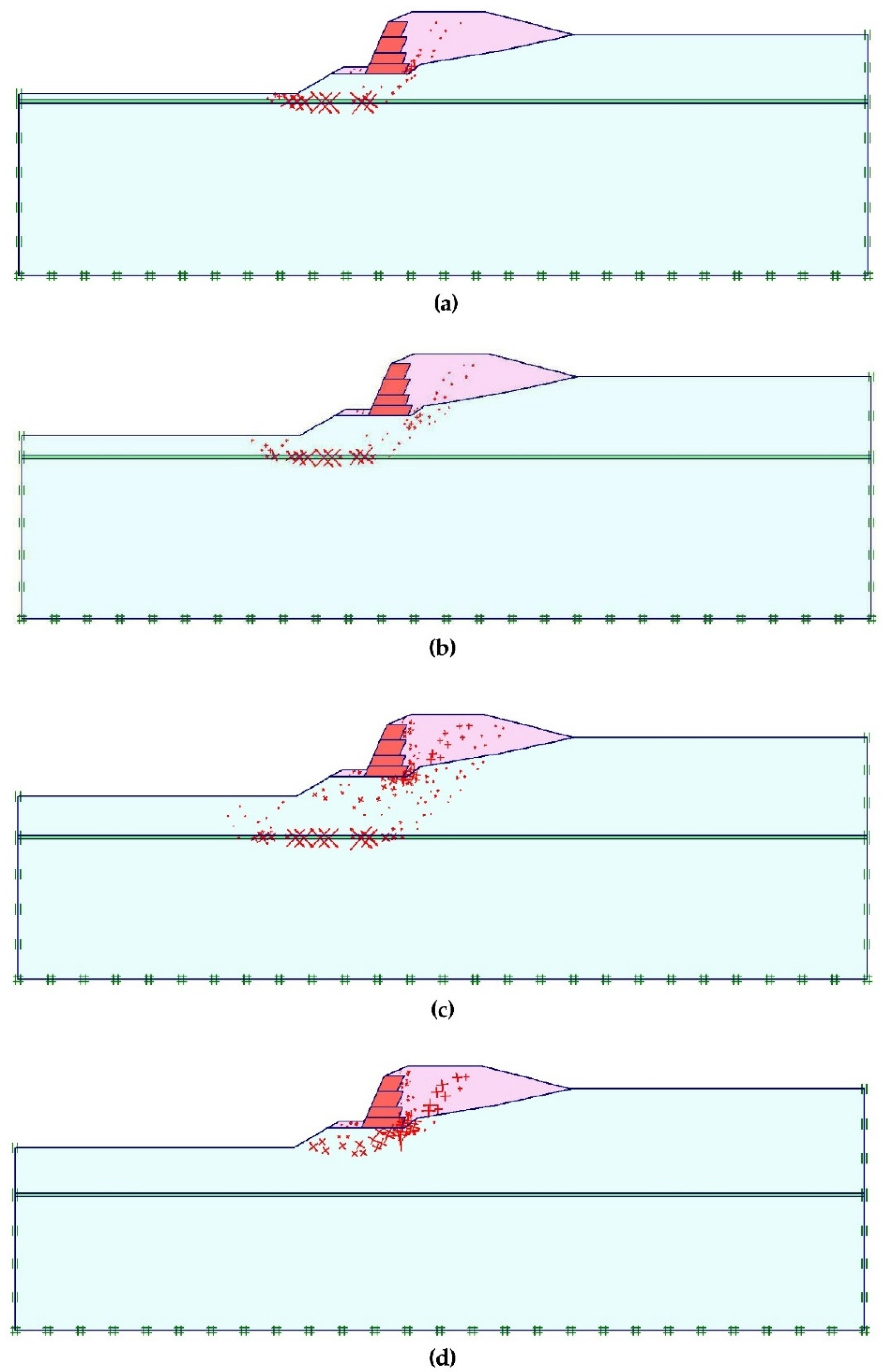
Figure 6 shows the calculated total strains for the same four cases, involving the weak layer, which were presented before. These representations show that the weak layer experiences the highest axial strain values when it affects the failure mechanism (Figure 6a–c). The unstable soil mass horizontally slides on the weak layer due to the shear strain experienced by the weak materials. This proves the fundamental role of the weak layer on the mechanical behaviour of the studied geotechnical system and, in particular, its effect on the global stability of the embankment and on the geometry of the failure mechanisms.
3.2. Influence of the Weak Layer on the Safety Factor
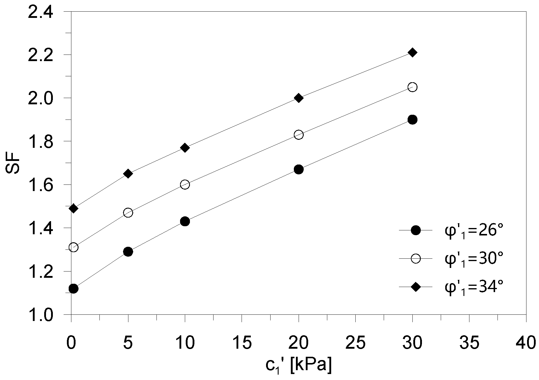
As reported before, to provide reference values of the safety factor (SF), preliminarily, the FE analyses were conducted considering homogeneous foundation soils. Figure 7 shows the evolution of the safety factor with intercept cohesion c′1, for different values of the shear strength angle φ′1 (26°, 30° and 34°) of foundation soils. Obviously, the safety factor increases both with intercept cohesion and with the shear strength angle. The similar trend of the curves proves that, in this case, the failure mechanism is not dependent on the shear strength parameters.
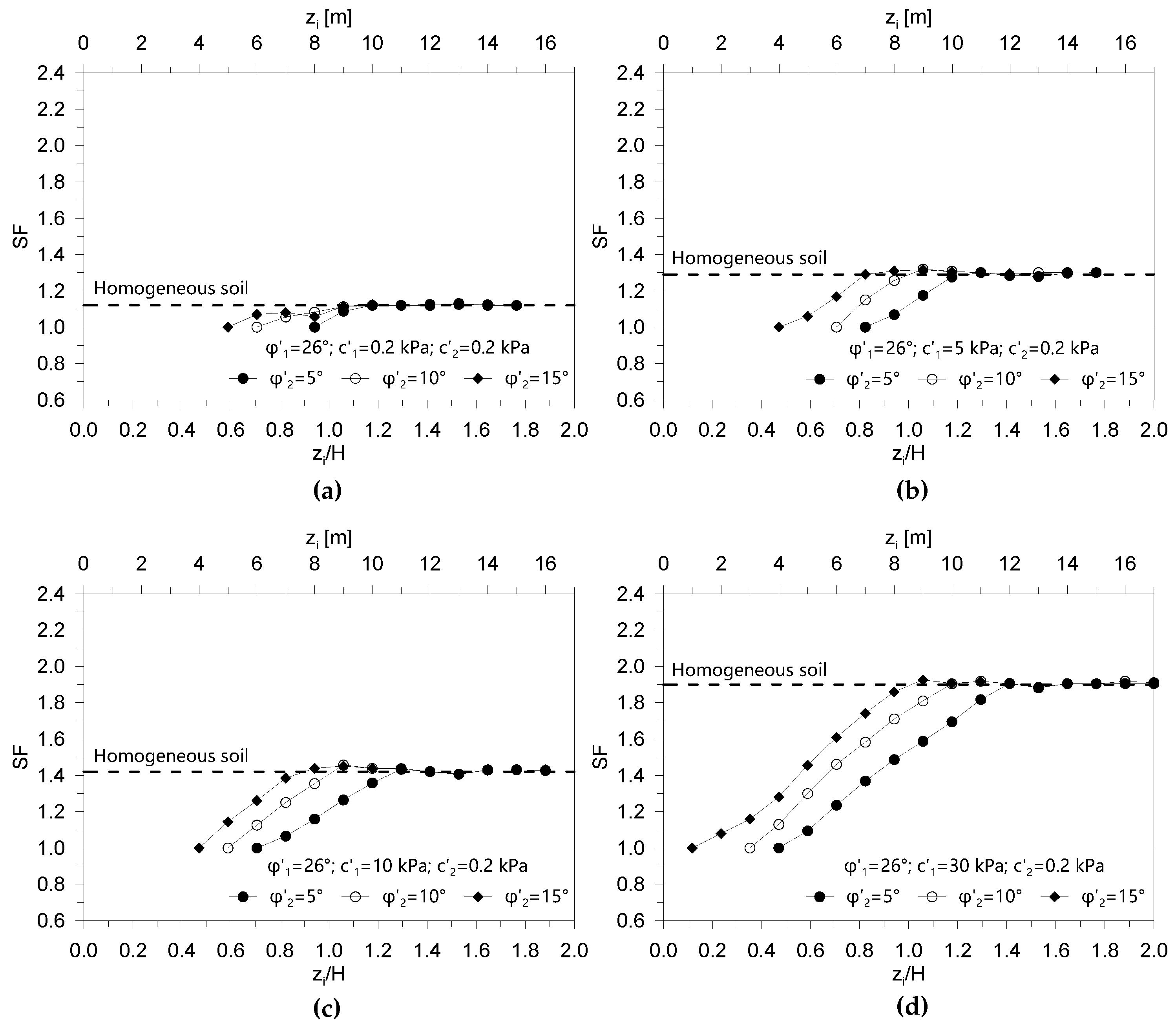
Figure 8, Figure 9 and Figure 10 report the values of the safety factor calculated as a function of geometrical properties variable zi/H, with variation in the different shear strength parameters for both the foundation soil and the weak layer (see Table 1).
In these analyses, considering constant shear strength parameters, the depth of the weak layer was varied. The results obtained show that when the weak layer is very deep, the safety factor does not depend on the strength parameters of the weak layer because the failure mechanism does not affect it. In this condition, the failure mechanism almost coincides with the case of the correspondent homogeneous foundation soils. Hence, the safety factor is practically equal to the corresponding one in a homogeneous condition. However, the depth at which the weak layer begins to influence the failure mechanism, and consequently the corresponding safety coefficient, is highly dependent on the strength of the weak layer. In all cases investigated, the shallower the weak layer, the lesser the safety factor is. The analyses conducted were stopped when the calculated SF became equal to 1 (failure).
The influence of the weak layer increases with the difference between the shear strength of the weak layer and the foundation soil. The presence of the weak layer within the failure mechanism can decrease the safety factor up to 60% of the corresponding safety factor in the case of the homogeneous foundation soil. The comparison between the data reported in Figure 8, Figure 9 and Figure 10 shows that SF = 1 was obtained for a depth of the weak layer, which depends on the shear strength of both the weak layer and the foundation soils.
For cases of zi/H lower than about 0.1 ÷ 0.5 (weak layer located very close to the foundation of the reinforced earth wall), stability is not possible for the parameters of the weak layer considered in the numerical analyses. Obviously, if the shear strength parameters of the weak layer were very similar to those of the foundation soils, this case would also present stability conditions. These cases are not represented in the results because they are not significant for the purpose of this study, and because, in the authors’ opinion, they are not significant from a practical point of view.
4. Discussion
The results of the FE analyses proved that when the weak layer is involved in the failure mechanism, the safety factor greatly decreases. In general, the five different scenarios depicted in Figure 11 and Figure 12 can be considered as representative of the geotechnical problem. In these figures, the cases of foundation soil with the following shear strength parameters c′1 = 10 kPa and φ′1 = 30° are represented, while the shear strength parameters of the weak layer are c′2 = 0.2 kPa and φ′2 = 10°. Similar failure mechanisms were obtained for other values of the shear strength parameters of the weak layer and foundation soils. The first mechanism (Figure 11) considers the homogeneous foundation soil and the safety factor resulting from the stability analysis is higher than 1 (SF0 >1). Overall stability conditions are ensured by the mechanical properties of the foundation soil and by the characteristics of the embankment (soil compaction, reinforcement geomembrane, depth of the foundation of the embankment). The failure mechanism is almost circular in shape.
The second one (Figure 12a) considers the presence of the weak layer at depth zi equal to z*, which is defined as the critical depth. As defined here, z* is the minimum depth of the weak layer, below which the overall stability condition is not ensured. In this condition, the safety factor SF is equal to 1. The failure mechanism largely affects the weak layer and becomes mixtilinear in shape. In the third scenario (Figure 12b), the weak layer is located at an intermediate depth between z* and zmax, and the calculated safety factor is between 1 and SF0. The depth zmax can be defined by means of the fourth scenario depicted in Figure 12c, which represents the case in which the weak layer is precisely located at depth equal to zmax. In this condition, the extension of the failure mechanism is the maximum, but it affects the weak layer to a limited extent. Hence, a reduced influence of the weak layer on the safety factor can be attained (SF ≈ SF0), even though the mixtilinear shape is maintained. The condition in which the layer is located at a depth higher than zmax is represented by the fifth scenario (Figure 12d). The failure mechanism mirrors the one observed in the case of homogeneous foundation soils, and the safety factor is the same (SF = SF0).
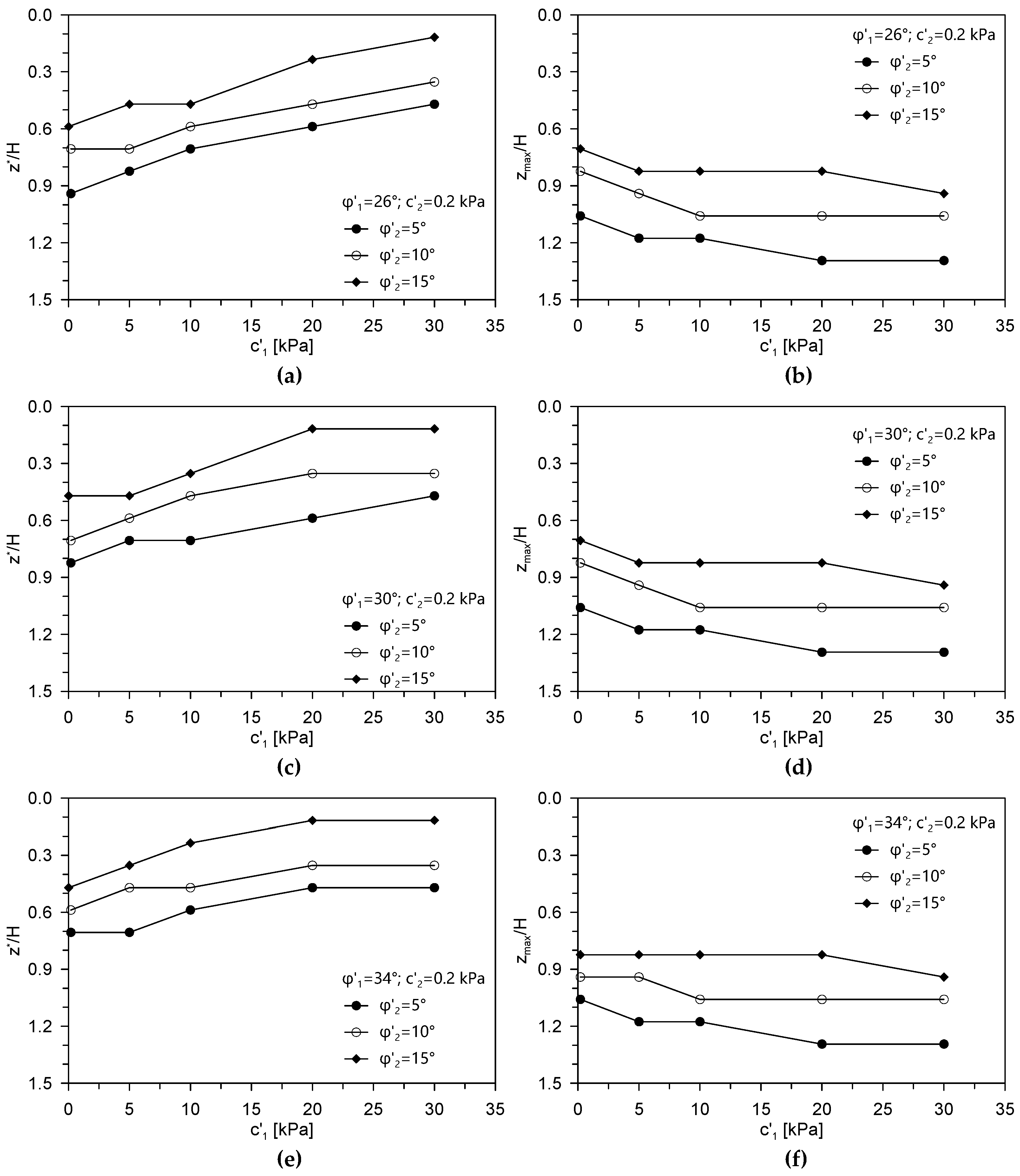
The parameters of the weak layer depth z* and zmax depend on the shear strength of the involved soils (both foundation soil and weak layer soil). According to this, the ratio between the critical depth z*and the height of the embankment H (z*/H) is plotted as a function of the intercept cohesion of the foundation soil c’1 and of the shear strength angle of the foundation soil (φ′1 = 26° in Figure 13a, φ′1 = 30° in Figure 13c and φ′1 = 34° in Figure 13e). The different values of the shear strength angle of the weak layer (φ′2 = 5°, 10° and 5°) are considered in the same figures. Similarly, the values of the ratio between the maximum depth zmax and the height of the embankment H (zmax/H) are plotted in Figure 13b (φ′1 = 26°), Figure 13d (φ′1 = 30°) and Figure 13f (φ′1 = 34°).
The data show that the intercept cohesion of the foundation soil has a different influence concerning the critical and maximum depths. The critical depth z* decreases while the maximum depth zmax rises with the increase in the intercept cohesion c′1. Conversely, the shear strength angle of the foundation soils φ′1 has a limited influence on the geometrical variable z*/H, while it almost does not affect parameter zmax/H. Hence, the domain in which the weak layer affects the overall stability of the embankment expands with the intercept cohesion of the foundation soil c′1.
Moreover, the data depicted in Figure 13 show that the decrease in the shear strength angle of the weak layer φ′2 raises both the geometrical variables z*/H and zmax/H. In other words, the soil volume within the foundation soil in which the weak layer can affect both the deformation mechanism and the safety factor increases with the difference between the shear strength of the weak layer and the foundation soil. A maximum value of zmax/H equal to about 1.3 was obtained in this study.
The numerical results obtained prove that the geotechnical characterization of the weak geomaterial within the layer is fundamental to evaluating the overall stability of the embankments, as well as of all geotechnical systems. Hence, despite the detecting difficulties (Terzaghi, 1929 [1]), particular attention must be paid during ground investigations to finding weak layers down to a significant depth. Considering their detrimental influence on the overall stability, geometrical characteristics of weak layers (depth, slope and thickness) should be investigated through careful drilling, and soil samples should be recovered within them. Hydro-mechanical properties of weak materials should be deeply evaluated by means of laboratory testing. Considering the potential origin of the weak layers (sedimentological, geochemical or geotechnical origin), the anisotropy of the hydro-mechanical properties should also be taken into account.
5. Conclusions
The paper presented a numerical study aiming to evaluate the mechanical behaviour of an embankment, constituted by a backfill and a reinforced earth wall, founded on a complex geotechnical situation. Specifically, a significant number of finite-element (FE) simulations, carried out by means of the code Plaxis 2D [32], were performed to evaluate the presence of a horizontal and thin weak layer within the foundation soil.
On the basis of the results obtained by means of finite-element modelling, the main conclusions can be drawn as follows.
The total displacements and strains resulting from the phi-c reduction calculation stages were considered to highlight the influence of the weak layer on the deformation mechanism at failure. In this regard, the analyses proved that the presence of the weak layer deeply modifies both the shape and the extension of the failure mechanisms. In fact, while in the case of homogeneous foundation soil the failure mechanism is almost circular in shape, when the weak layer is located at a significant depth from the foundation plane of the embankment the failure mechanism becomes mixtilinear in shape and affects a larger soil volume.
The weak layer has a great influence on the overall stability of the considered embankment. In fact, the results obtained prove that the calculated safety factor reduces with a decrease in the depth of the weak layer. This is due to the concentration of strains within the weak layer and the reduced capability to transfer the shear stress to the underlying soils. The detrimental effect on the global safety factor increases with the difference between the shear strength parameters of the considered soils (weak layer and foundation soils). The presence of the weak layer within the failure mechanism can decrease the safety factor up to 60% of the corresponding safety factor in the case of homogeneous foundation soil.
The extension of the soil volume involved in the failure mechanism was deeply evaluated. Two different geometrical parameters of the weak layer were extracted from the FE models and considered for evaluation of the depth at which the safety factor becomes unitary (critical depth) and the depth at which a negligible influence on the safety factor can be attained despite the failure mechanism being always mixtilinear in shape (maximum depth). The numerical analyses again point out the fundamental effect of the layer and of the reduced strength of the weak material. In fact, the extension of the soil volume involved in the failure mechanism increases with the difference between the shear strength of the foundation soil and of the weak layer.
This numerical research suggests to give even more weight to ground investigation of weak layers within a significant geotechnical volume. In fact, considering that, in the presence of weak layers, even embankments that if founded on homogeneous soils would have very high global safety factors can become unstable, a detailed geotechnical investigation aimed at finding weak layers down to a significant depth should be conducted when some preliminary knowledge (e.g., site geological characterization) may suggest the possible presence of weak layers. Particular attention must be paid to very thin layers, which are still capable of deeply affecting the field behaviour of geotechnical systems. Considering that the extension of the soil volume involved in the failure mechanism is also a function of the geotechnical parameters of the same layer, a preliminary assessment of the weakness of the layered material can be useful during the execution of ground investigation to update the soil volume to be explored.
Author Contributions
All authors contributed equally to the work. All authors have read and agreed to the published version of the manuscript.
Funding
No funding was used for the research.
Conflicts of Interest
The authors declare no conflict of interest.
References
- Terzaghi, K. Effects of minor geologic details on the safety of dams. In Geology and Engineering for Dams and Reservoirs, American Institute of Mining and Metallurgical Engineers; Technical Publication 215; American Society of Civil Engineers: Reston, VA, USA, 1929; pp. 31–44. [Google Scholar]
- Leonards, G.A. Investigation of failures. J. Geotech. Eng. Div. ASCE 1982, 108, 222–283. [Google Scholar]
- Silvestri, V. The bearing capacity of dikes and fills founded on soft soils of limited thickness. Can. Geotech. J. 1983, 20, 428–436. [Google Scholar] [CrossRef]
- Scott, R.F. Failure. Géotechnique 1987, 37, 423–466. [Google Scholar] [CrossRef] [Green Version]
- Rowe, P.W. A reassessment of the causes of the Carsington embankment failure. Géotechnique 1991, 41, 395–421. [Google Scholar] [CrossRef]
- Michalowski, R.L. Limit analysis of weak layers under embankments. Soils Found. 1993, 1993. 33, 155–168. [Google Scholar] [CrossRef] [Green Version]
- Skempton, A.W.; Vaughan, P.R. The failure of Carsington dam. Géotechnique 1993, 43, 151–173. [Google Scholar] [CrossRef]
- Picarelli, L. Resistenza e meccanismi di rottura nei terreni naturali. In Proceedings of the Convegno Gruppo Naz. Coord. Studi Ingegneria Geotecnica, CNR, Sul Tema: Deformazioni in Prossimita Della Rottura e Resistenza dei Terreni Naturali e Delle Rocce, Ravello, Salerno, Italy, 27–28 February 1991; Volume 2, pp. 7–61. (In Italian). [Google Scholar]
- D’Elia, B.; Picarelli, L.; Leroueil, S.; Vaunat, J. Geotechnical characterisation of slope movements in structurally complex clay soils and stiff jointed clays. Riv. Ital. Geotec. 1998, 32, 5–32. [Google Scholar]
- Valore, C.; Ziccarelli, M.; Muscolino, S.R. The bearing capacity of footings on sand with a weak layer. Geotech. Res. 2017, 4, 12–29. [Google Scholar] [CrossRef] [Green Version]
- Ziccarelli, M.; Valore, C.; Muscolino, S.R.; Fioravante, V. Centrifuge tests on strip footings on sand with a weak layer. Geotech. Res. 2017, 4, 47–64. [Google Scholar] [CrossRef] [Green Version]
- Kardos, L.T.; Vlasoff, P.I.; Twiss, S.N. Factors contributing to landslides in the Palouse Region. Soil Sci. Soc. Am. J. 1944, 8, 437–440. [Google Scholar] [CrossRef]
- Lewis, K.B. Slumping on a continental slope inclined at 1°–4°. Sedimentology 1971, 16, 97–110. [Google Scholar] [CrossRef]
- Summerhayes, C.P.; Bornhold, B.D.; Embley, R.W. Surficial slides and slumps on the continental slope and rise of South West Africa: A reconnaissance study. Mar. Geol. 1979, 31, 265–277. [Google Scholar] [CrossRef]
- Locat, A.; Lee, H.J. Submarine landslides: Advances and challanges. Can. Geotech. J. 2002, 39, 193–212. [Google Scholar] [CrossRef]
- L’Heureux, J.S.; Longva, O.; Steiner, A.; Hansen, L.; Vardy, M.E.; Vanneste, M.; Haflidason, H.; Brendryen, J.; Kvalstad, T.J.; Forsberg, C.F.; et al. Identification of weak layers and their role for the stability of slopes at Finneidfjord, Northern Norway. In Submarine Mass Movements and Their Consequences. Advances in Natural and Technological Hazards Research; Yamada, Y., Kawamura, K., Ikehara, K., Ogawa, Y., Urgeles, R., Mosher, D., Chaytor, J., Strasser, M., Eds.; Springer: Dordrecht, The Netherlands, 2012; Volume 31, pp. 321–330. [Google Scholar] [CrossRef]
- Airò Farulla, C.; Cafiso, F.; Calvi, F.; Rosone, M. Safeguarding historic towns on hilltops threatened by land sliding: The case of San Fratello in Sicily. Riv. Ital. Geotec. 2015, 49, 7–28. [Google Scholar]
- Locat, A.; Leroueil, S.; Fortin, A.; Demers, D.; Jostad, H.P. The 1994 landslide at Sainte-Monique, Quebec: Geotechnical investigation and application of progressive failure analysis. Can. Geotech. J. 2015, 52, 490–504. [Google Scholar] [CrossRef]
- Valore, C.; Ziccarelli, M. The stabilization of a slope-viaduct system without closing traffic. In Proceedings of the XVI ECSMGE, Edinburg, UK, 13–17 September 2015; Winter, M.G., Smith, D.M., Eldred, P.J.L., Toll, D.G., Eds.; ICE Publishing: New York, NY, USA, 2015; pp. 367–372. [Google Scholar]
- Zhang, W.; Wang, D.; Randolph, M.F.; Puzrin, A.M. Catastrophic failure in planar landslides with a fully softened weak zone. Géotechnique 2015, 65, 755–769. [Google Scholar] [CrossRef] [Green Version]
- Dey, R.; Hawlader, B.C.; Phillips, R.; Soga, K. Numerical modelling of submarine landslides with sensitive clay layers. Géotechnique 2016, 66, 454–468. [Google Scholar] [CrossRef]
- Rosone, M.; Ziccarelli, M.; Ferrari, A.; Airò Farulla, C. On the reactivation of a large landslide induced by rainfall in highly fissured clays. Eng. Geol. 2018, 235, 20–38. [Google Scholar] [CrossRef]
- Shan, A.; Zhang, W.; Wang, D.; Wang, L. Numerical investigations of retrogressive failure in sensitive clays: Revisiting 1994 Sainte-Monique slide, Quebec. Landslides 2020. [Google Scholar] [CrossRef]
- Zhang, W.; Randolph, M.F.; Alexander, M.; Puzrin, A.M.; Wang, D. Criteria for planar shear band propagation in submarine landslides along weak layers. Landslides 2020, 17, 855–876. [Google Scholar] [CrossRef]
- Zhang, W.; Wang, D. Stability analysis of cut slope with shear band propagation along a weak layer. Comput. Geotech. 2020, 125, 103676. [Google Scholar] [CrossRef]
- Heierli, J.; Zaiser, M. Failure initiation in snow stratifications containing weak layers: Nucleation of whumpfs and slab avalanches. Cold Reg. Sci. Technol. 2008, 52, 385–400. [Google Scholar] [CrossRef]
- Birkeland, K.W.; van Herwijnen, A.; Reuter, B.; Bergfeld, B. Temporal changes in the mechanical properties of snow related to crack propagation after loading. Cold Reg. Sci. Technol. 2019, 159, 142–152. [Google Scholar] [CrossRef]
- Rosendahl, P.; Philipp Weißgraeber, P. Modeling snow slab avalanches caused by weak-layer failure–Part 1: Slabs on compliant and collapsible weak layers. Cryosphere 2020, 14, 115–130. [Google Scholar] [CrossRef] [Green Version]
- Locat, J.; Leroueil, S.; Locat, A.; Lee, H. Weak layers: Their definition and classification from a geotechnical perspective. In Submarine Mass Movements and Their Consequences. Advances in Natural and Technological Hazards Research; Krastel, S., Behrmann, J.-H., Volker, D., Stipp, M., Berndt, C., Urgeles, R., Chayton, J., Harbitz, C.B., Eds.; Springer: Dordrecht, The Netherlands, 2014; Volume 37, pp. 3–12. [Google Scholar] [CrossRef]
- Shi, Z.; Zhao, S.; Qiao, Y.; He, M. Stability analysis of an expansive soil-embankment slope with a soft interlayer. IOP Conf. Ser. Earth Environ. Sci. 2020, 570, 032022. [Google Scholar] [CrossRef]
- Ziccarelli, M.; Rosone, M. Lavori di Ammodernamento SS121–Dissesti sui Rilevati in Località Scorciavacche (SS121 Modernization Works—Damages on the Embankments in “Scorciavacche”); Department of Engineering, University of Palermo: Palermo, Italy, 2015; Unpublished Report. [Google Scholar]
- Plaxis, Plaxis 2D, Version 8.6. 2008. Available online: http://www.plaxis.nl/ (accessed on 18 October 2020).
- Terzaghi, K. Mechanism of landslides. In Application of Geology to Engineering Practice (Berkey Volume); Paige, S., Ed.; Geological Society of America: New York, NY, USA, 1950; pp. 83–123. [Google Scholar] [CrossRef]
- Hutchinson, J.N. Assessment of the effectiveness of corrective measures in relation to geological conditions and types of slope movement. Bull. Int. Assoc. Eng. Geol. Bull. Assoc. Int. Géol. Ingénieur 1977, 16, 131–155. [Google Scholar] [CrossRef]
- Holtz, R.D.; Schuster, R.L. Stabilization of soil slopes. In Special Report 247, Landslides: Investigation and Mitigation; Turner, A.K., Schuster, R.L., Eds.; Transport Res Board, National Academy Press: Washington, DC, USA, 1996; pp. 439–473. [Google Scholar]
- Rahardjo, H.; Hritzuk, K.J.; Leong, E.C.; Rezaur, R.B. Effectiveness of horizontal drains for slope stability. Eng. Geol. 2003, 69, 295–308. [Google Scholar] [CrossRef]
- Marzulli, V.; Cafaro, F.; Ziccarelli, M. Hydraulic characterization of a pervious concrete for deep draining trenches. J. Mater. Civil Eng. ASCE 2018, 30. [Google Scholar] [CrossRef] [Green Version]
- Ziccarelli, M.; Valore, C. Hydraulic conductivity and strength of pervious concrete for deep trench drains. Geomech. Energy Environ. 2019, 18, 41–55. [Google Scholar] [CrossRef]
- Rosone, M.; Ferrari, A. Water retention behaviour of compacted and reconstituted scaly clays. E3S Web Conf. 2020, 195, 03026. [Google Scholar] [CrossRef]
- Farulla, C.A.; Rosone, M. Modeling Round Robin test: An uncoupled approach. Procedia Earth Planet. Sci. 2014, 9, 195–200. [Google Scholar] [CrossRef] [Green Version]
- Moraci, N.; Gioffrè, D. La progettazione di rilevati su terreni compressibili rinforzati con geosintetici. Riv. Ital. Geotec. 2010, 3, 67–100. [Google Scholar]
- Airò Farulla, C.; Celauro, B.; Celauro, C.; Rosone, M. Field test of lime treatment of clayey soils for railways and road works. Ing. Ferrov. 2014, 69, 729–752. [Google Scholar]
Figure 1.
Scheme for formulation of the problem: the weak layer is horizontal and is located at depth zi. Depth zi is measured from the foundation plane of the reinforced earth wall. The boundary conditions and the dimensions of the finite-element (FE) model are also represented in the figure.
Figure 1.
Scheme for formulation of the problem: the weak layer is horizontal and is located at depth zi. Depth zi is measured from the foundation plane of the reinforced earth wall. The boundary conditions and the dimensions of the finite-element (FE) model are also represented in the figure.

Figure 2.
FEM mesh employed for the case of zi/H = 1.18.

Figure 3.
Distribution of the total displacements at failure calculated for the case of homogeneous foundation soils (c′1 = 10 kPa and φ′1 = 30°), by means of the phi-c reduction stage. The colorimetric scale is not plotted in the figure because, as is well known, the intensity of displacement at failure calculated by the model is an unrealistic result, due to the elastoplastic constitutive soil model adopted in the simulations. However, this representation is effective in pointing out the volume of materials involved in the failure (volume in which the displacements and the deformation are concentrated).

Figure 4.
Total strain at failure calculated for the case of homogeneous foundation soils (c′1 = 10 kPa and φ′1 = 30°) by means of the phi-c reduction stage. The length and the direction of the arrows represent the intensity and the direction, respectively, of the principal strains. The concentration of the strains identifies a global failure mechanism.

Figure 5.
Spatial distribution of the total displacements at failure calculated for the case of a horizontal weak layer with c′2 = 0.2 kPa and φ′2 = 10° located at depth equal to (a) zi = 4 m (zi/H = 0.47), (b) zi = 6 m (zi/H = 0.71), (c) zi = 9 m (zi/H = 1.06) and (d) zi = 10 m (zi/H = 1.18).
Figure 5.
Spatial distribution of the total displacements at failure calculated for the case of a horizontal weak layer with c′2 = 0.2 kPa and φ′2 = 10° located at depth equal to (a) zi = 4 m (zi/H = 0.47), (b) zi = 6 m (zi/H = 0.71), (c) zi = 9 m (zi/H = 1.06) and (d) zi = 10 m (zi/H = 1.18).

Figure 6.
Total strain at failure for the case of the horizontal weak layer with c′2 = 0.2 kPa and φ′2 = 10° located at depth equal to (a) zi = 4 m (zi/H = 0.47), (b) zi = 6 m (zi/H = 0.71), (c) zi = 9 m (zi/H = 1.06) and (d) zi = 10 m (zi/H = 1.18).
Figure 6.
Total strain at failure for the case of the horizontal weak layer with c′2 = 0.2 kPa and φ′2 = 10° located at depth equal to (a) zi = 4 m (zi/H = 0.47), (b) zi = 6 m (zi/H = 0.71), (c) zi = 9 m (zi/H = 1.06) and (d) zi = 10 m (zi/H = 1.18).

Figure 7.
Safety factor SF as a function of the intercept cohesion c′1, for different values of the shear strength angle φ′1 (26°, 30° and 34°) in the case of homogeneous foundation soils.
Figure 7.
Safety factor SF as a function of the intercept cohesion c′1, for different values of the shear strength angle φ′1 (26°, 30° and 34°) in the case of homogeneous foundation soils.

Figure 8.
Safety factor SF as a function of the geometrical variable zi/H for φ′1 = 26° and c′1 = 0.2 kPa (a), c′1 = 5 kPa (b), c′1 = 10 kPa (c) and c′1 = 30 kPa (d), for different values of the shear strength angle φ′2 (5°, 10° and 15°).
Figure 8.
Safety factor SF as a function of the geometrical variable zi/H for φ′1 = 26° and c′1 = 0.2 kPa (a), c′1 = 5 kPa (b), c′1 = 10 kPa (c) and c′1 = 30 kPa (d), for different values of the shear strength angle φ′2 (5°, 10° and 15°).

Figure 9.
Safety factor SF as a function of the geometrical variable zi/H for φ′1 = 30° and c′1 = 0.2 kPa (a), c′1 = 5 kPa (b), c′1 = 10 kPa (c) and c′1 = 30 kPa (d), for different values of the shear strength angle φ′2 (5°, 10° and 15°).
Figure 9.
Safety factor SF as a function of the geometrical variable zi/H for φ′1 = 30° and c′1 = 0.2 kPa (a), c′1 = 5 kPa (b), c′1 = 10 kPa (c) and c′1 = 30 kPa (d), for different values of the shear strength angle φ′2 (5°, 10° and 15°).

Figure 10.
Safety factor SF as a function of the geometrical variable zi/H for φ′1 = 34° and c′1 = 0.2 kPa (a), c′1 = 5 kPa (b), c′1 = 10 kPa (c) and c′1 = 30 kPa (d), for different values of the shear strength angle φ′2 (5°, 10° and 15°).
Figure 10.
Safety factor SF as a function of the geometrical variable zi/H for φ′1 = 34° and c′1 = 0.2 kPa (a), c′1 = 5 kPa (b), c′1 = 10 kPa (c) and c′1 = 30 kPa (d), for different values of the shear strength angle φ′2 (5°, 10° and 15°).

Figure 11.
Significant scenario representing the failure mechanism and the stability condition (safety factor SF0 > 1) of the embankment in the case of homogeneous foundation soil. The failure mechanism has been drawn on the basis of the numerical results, in particular of the concentration of the shear strain in the phi-c reduction phase.

Figure 12.
Significant scenario representing the failure mechanism and the stability condition of the embankment in the case of the weak layer located at different depths. The weak layer affects both the failure mechanism and the safety factor: (a) weak layer located at depth zi equal to the critical depth z* (SF = 1); (b) weak layer located at depth zi between the critical depth z* and the maximum depth zmax (1 < SF < SF0, where SF0 is the safety factor in case of homogenous foundation soil); (c) weak layer located at depth equal to the maximum depth zmax (SF ≈ SF0); (d) weak layer located at a depth higher than the maximum depth zmax (SF = SF0).

Figure 13.
Evolution of the ratio between the critical depth z*and the height of the embankment H and of the ratio between the maximum depth zmax and the height of the embankment H as a function of the intercept cohesion of the foundation soil c1’ and of the shear strength angle of the foundation soil. (a,b) φ1′ = 26°, (c,d) φ1′ = 30°, (e,f) φ1′ = 34°.


Table 1.
Dimensions of the scheme for formulation of the problem.
| L1 (m) | L2 (m) | L3 (m) | L4 (m) | L5 (m) | L6 (m) | H (m) | β (°) | a (m) | zi (m) | t0 (m) | B (m) |
|---|---|---|---|---|---|---|---|---|---|---|---|
| 28 | 37 | 45 | 42.5 | 11.5 | 32 | 8.5 | 11 | 3 | 0 ÷ 17 | 0.5 | 130 |
Table 2.
Geotechnical parameters of materials used in the numerical analyses. γd: dry unit weight; γsat: saturated unit weight; c′: effective intercept cohesion; φ′: effective shear strength angle; Ψ′: dilation angle; E′: Young modulus; ν′: Poisson’s ratio. The elastic–perfectly plastic Mohr–Coulomb constitutive model was used for all modelled soils.
| Material | γd (kN/m3) | γsat (kN/m3) | φ′ (°) | Ψ′ (°) | c′ (kPa) | E′ (MPa) | ν′ (-) |
|---|---|---|---|---|---|---|---|
| Embankment | 17 | 20 | 36 | 10 | 1 | 20 | 0.30 |
| Reinforced earth | 17 | 20 | 36 | 10 | 100 | 20 | 0.30 |
| Foundation soil | 16 | 18 | 26, 30, 34 | 0 | 0.2, 5, 10, 20, 30 | 10 | 0.35 |
| Weak layer | 16 | 18 | 5, 10, 15 | 0 | 0.2 | 10 | 0.35 |
Publisher’s Note: MDPI stays neutral with regard to jurisdictional claims in published maps and institutional affiliations. |
© 2021 by the authors. Licensee MDPI, Basel, Switzerland. This article is an open access article distributed under the terms and conditions of the Creative Commons Attribution (CC BY) license (http://creativecommons.org/licenses/by/4.0/).
Share and Cite
MDPI and ACS Style
Ziccarelli, M.; Rosone, M. Stability of Embankments Resting on Foundation Soils with a Weak Layer. Geosciences 2021, 11, 86. https://0-doi-org.brum.beds.ac.uk/10.3390/geosciences11020086
AMA Style
Ziccarelli M, Rosone M. Stability of Embankments Resting on Foundation Soils with a Weak Layer. Geosciences. 2021; 11(2):86. https://0-doi-org.brum.beds.ac.uk/10.3390/geosciences11020086
Chicago/Turabian StyleZiccarelli, Maurizio, and Marco Rosone. 2021. "Stability of Embankments Resting on Foundation Soils with a Weak Layer" Geosciences 11, no. 2: 86. https://0-doi-org.brum.beds.ac.uk/10.3390/geosciences11020086
Note that from the first issue of 2016, this journal uses article numbers instead of page numbers. See further details here.