Article

The Gavorrano Monzogranite (Northern Apennines): An Updated Review of Host Rock Protoliths, Thermal Metamorphism and Tectonic Setting

1
Department of Earth and Geoenvironmental Sciences, University of Bari, 70125 Bari, Italy
2
CNR-IGG Pisa, Institute of Geosciences and Earth Resources, 56127 Pisa, Italy
3
Department of Physics and Geology, University of Perugia, 06123 Perugia, Italy
4
Department of Earth Sciences, University of Florence, 50121 Firenze, Italy
5
Tuscan Mining UNESCO Global Geopark, Parco Tecnologico Archeologico delle Colline Metallifere Grossetane, 58100 Gavorrano, Italy
6
Department of Physics, Earth and Environmental Sciences, University of Siena, 53100 Siena, Italy
*
Author to whom correspondence should be addressed.
Submission received: 28 December 2020 / Revised: 22 February 2021 / Accepted: 1 March 2021 / Published: 8 March 2021

Abstract

:
We review and refine the geological setting of an area located nearby the Tyrrhenian seacoast, in the inner zone of the Northern Apennines (southern Tuscany), where a Neogene monzogranite body (estimated in about 3 km long, 1.5 km wide, and 0.7 km thick) emplaced during early Pliocene. This magmatic intrusion, known as the Gavorrano pluton, is partially exposed in a ridge bounded by regional faults delimiting broad structural depressions. A widespread circulation of geothermal fluids accompanied the cooling of the magmatic body and gave rise to an extensive Fe-ore deposit (mainly pyrite) exploited during the past century. The tectonic setting which favoured the emplacement and exhumation of the Gavorrano pluton is strongly debated with fallouts on the comprehension of the Neogene evolution of this sector of the inner Northern Apennines. Data from a new fieldwork dataset, integrated with information from the mining activity, have been integrated to refine the geological setting of the whole crustal sector where the Gavorrano monzogranite was emplaced and exhumed. Our review, implemented by new palynological, petrological and structural data pointed out that: (i) the age of the Palaeozoic phyllite (hosting rocks) is middle-late Permian, thus resulting younger than previously described (i.e., pre-Carboniferous); (ii) the conditions at which the metamorphic aureole developed are estimated at a temperature of c. 660 °C and at a depth lower than c. 6 km; (iii) the tectonic evolution which determined the emplacement and exhumation of the monzogranite is constrained in a transfer zone, in the frame of the extensional tectonics affecting the area continuously since Miocene.

1. Introduction

The inner Northern Apennines (i.e., northern Tyrrhenian Sea and southern Tuscany), after having experienced HP/LT metamorphism during late Oligocene-early Miocene [1,2,3] was affected by extension since Burdigalian [4]. The clearest evidence of this process is the opening of the Tyrrhenian Basin [5] and the present 20–26 and 30–50 km crustal and lithospheric thickness, respectively [6,7,8]. Extension favoured partial melting in the lower crust and in the mantle, thus generating crustal and hybrid magmas (Tuscan Magmatic Province: [9,10] for a review). Igneous activity and extensional tectonics migrated eastwards [11,12,13]: hence, the first magmatic evidence occurred during middle Miocene in Corsica (Sisco lamproite, 14 Ma), and then, in the Tuscan archipelago (Late Miocene-Pliocene) and southern Tuscany (Pliocene-Pleistocene), up to the presently cooling magmatic bodies [14,15,16,17,18]. These are producing relevant geothermal anomalies [19], as it is the case for the Monte Amiata [14,20] and Larderello [15,18,21] areas [22,23]. In the inner Northern Apennines (Figure 1), intrusive bodies, emplaced at <10 km depth, are partially exposed in the Tuscan Archipelago and southern Tuscany, where crustal uplift and extensional tectonics induced their exhumation ([24] with references therein).
The Gavorrano pluton is an example of this process [25]. Such a pluton is an about 3 km3 laccolith [26], dated at 4.9 Ma [27] and partially exposed few kms to the east of the Tyrrhenian seacoast (Figure 1). It consists of cordierite-bearing monzogranite [28] with references therein with K-feldspar phenocrysts (up to 10 cm long), intruded by tourmaline-rich microgranite, porphyritic and aplitic dykes [25]. This magmatic intrusion and its contact aureole were mined from the last decades of the 19th century up to the 1981, to exploit sulphide (mainly pyrite) ore deposit, mostly occurring at the boundary between the igneous and host rocks, and in fault zones [29]. Although numerous studies were dedicated to this pluton, with the aim to reconstruct genesis and setting of the ore deposits (e.g., [26,29,30,31]), contrasting interpretations still remain with regards to: (i) the nature and age of the quartzitic-phyllite hosting rocks, contrastingly referred to Permian [32] or pre-Carboniferous [33]; (ii) the thermal conditions across the contact aureole and the related P-T peak conditions in the contact aureole, pointing to significantly different emplacement depths (cfr. [25,26,34]); (iii) the tectonic evolution of the Gavorrano area that was explained in extensional (e.g., [25,29]), transtensional [35] or compressional framework [34,36]. The compressional setting was also taken into account by [37,38] to explain the emplacement of the Gavorrano pluton, assumed to be contemporaneous to Pliocene regional thrusts and associated roof-anticlines. In this scenario, these authors considered the Gavorrano pluton as a key example for explaining the pluton emplacement in a compressional scenario, basically active since the Cretaceous in the inner Northern Apennines and northern Tyrrhenian sea.
In this paper, the state of the art on these themes, the contrasting interpretations, and hypotheses are discussed in the frame of new datasets. As a main conclusion: (i) we document the Permian age of the quartzitic-phyllite hosting rocks; (ii) we point to a peak temperature of c. 660 °C at a maximum pressure of 150 MPa for the metamorphic conditions in the contact aureole; and iii) we reconstruct the deformation within that sector of a Neogene regional transfer zone, which controlled the emplacement and exhumation of the Gavorrano pluton in the extensional framework characterizing inner Northern Apennines.

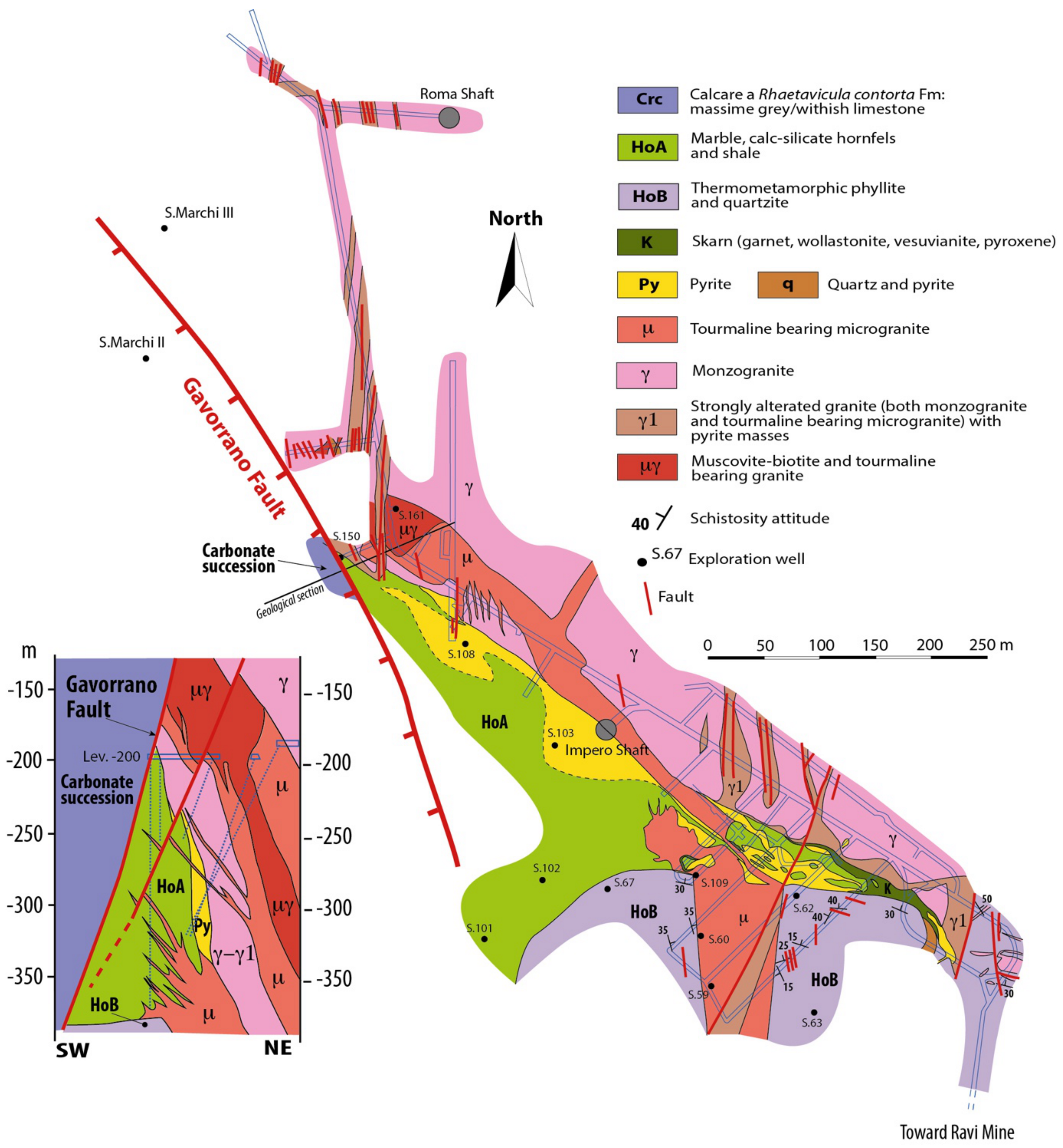
2. Geological Outline

The Gavorrano pluton intruded the lower part of the Tuscan Unit, following the main foliations and lithological boundaries (Figure 2) in the Palaeozoic-Triassic quartzite and phyllite, Triassic metacarbonate and late Triassic evaporite successions [25,29,39]. These rocks experienced, therefore, LP-metamorphism making particularly problematic the age attribution of the quartzitic-phyllite hosting rocks, contrastingly referred to Permian [32] or pre-Carboniferous [33], with different fallouts on the palaeogeography and context in which the overlying Triassic succession took place.
The initial studies on the intrusive rocks were carried out by [40,41,42,43,44]. Marocchi [44] firstly described the Gavorrano granite as a magmatic complex formed by a porphyritic granite, a tourmaline-bearing microgranite and mica-bearing microgranite. Furthermore, Martelli [45] presented a geochemical and crystallographic study of both magmatic rocks and pyrite, hence describing, for the first time, the habitus and morphology of the pyrite and K-feldspar. However, the most complete paper dealing with the Gavorrano intrusion was published by [25], who defined the porphyritic granite as a quartz-monzonite, crossed by tourmaline-rich microgranite and aplitic dykes. Barberi et al. [46] implemented the study of the pluton, in the meantime dated at 4.9 Ma by K/Ar radiometric data [27].
The laccolithic shape of the magmatic intrusion was constrained by data from the underground mining activity [29] and finally defined by [47] as a body with a maximum length of 3 km, a width of 1.7 km and a thickness of 0.7 km.
The depth of the Gavorrano granite emplacement was estimated by [26] at a maximum value of 2–2.5 km, corresponding to a lithostatic pressure lower than 100 MPa. Differently, [47] indicate a maximum depth ranging between 4 and 5 km, corresponding to a lithostatic pressure lower than 200 MPa.
Magma cooling was accompanied by a significant hydrothermal process that led to pyrite ore deposits. Mining activity was carried out nearby the partially exposed monzogranite (Figure 3a,b).
Exploitation was encompassed between the end of nineteenth century and the last decades of the twentieth century, having produced about 25 million tons of pyrite [26]. Pyrite formed within a quartz-calcite gangue, with minor content of galena, sphalerite, chalcopyrite, fluorite, marcasite, barite, realgar and stibnite [26,29]. Three main pyrite bodies (named as Rigoloccio, Massa Boccheggiano and Valmaggiore) were distinguished, and exploited in an interconnected network of more than 30 km long tunnels belonging to five distinct mines [29]: Rigoloccio, Gavoranno, Ravi Marchi, Ravi Montecatini, Valmaggiore (Figure 3a). Several studies were addressed to the origin of the ore body and to its geometrical setting and attitude [26,29,30,31,43,48,49,50,51,52,53,54,55,56,57,58,59,60,61,62,63,64,65]. On the basis of these results, two main contrasting models were proposed for the genesis of the ore deposit: (i) an epigenetic origin related to the emplacement and cooling of the magmatic intrusion (e.g., [25,26,29,49,51,52,55,60,65,66,67]) and (ii) a sedimentary/metamorphic origin (e.g., [61,62,68,69]). Geochemical and isotopic studies from [70,71,72,73,74,75,76] and [65] described the distribution of minor elements within the pyrite and sphalerite, as well as the chemistry of the igneous and hosting metamorphic rocks, thus providing information on the origin of the mineralization; accordingly, the origin of the sulfur is partly referred to the magmatic source and partly to the remobilization of sedimentary rocks, by means of geothermal fluids. These latter were strictly controlled by permeable volumes in fault zones, active during the geothermal circulation [29] and by lithological discontinuities hydraulically connected with the fault zones. Ore bodies are in fact located: (i) at the boundary between the monzogranite and hosting rocks (Figure 4); (ii) along the contact separating the Tuscan metamorphic unit from the overlying late Triassic evaporite [26,29] (Figure 3 and Figure 4); (iii) along normal faults juxtaposing sedimentary rocks with the magmatic intrusion (e.g., Monticello Fault, Figure 5).
Today, the intrusive rocks are partially exposed at surface or were tunneled at shallow depth in tunnels dug during the mining activity (Figure 3a,b). Their exhumation was controlled by normal faults, well-constrained in terms of geometry and displacements by means of surface and mining data [26,29,35].
Main faults were named as Gavorrano (NNW-SSE striking) and Monticello (N-S striking) faults, delimiting the western and eastern margins of the pluton, respectively (Figure 3a,b). The Gavorrano Fault is described as a west dipping high angle normal fault (60–70°) and with an arcuate geometry [29]. Its total offset exceeds 600 m. The Monticello Fault is a middle-angle (35–50°) normal fault dipping to the east and is characterized by a total offset of about 1000 m [29]. Mining data highlight that the Gavorrano and Monticello Faults intersect each other in proximity of the Ravi village (Figure 3a). Both faults are mineralized although with different hydrothermal parageneses: the Gavorrano Fault hosts pyrite-ore bodies associated to minor content of galena, chalcopyrite and blend [29]. Differently, the Monticello Fault was mineralized by a hydrothermal mineral paragenesis made up of quartz, barite, celestine, pyrite/marcasite, stibnite, fluorite, orpiment/realgar (Figure 5).
The northern margin of the Gavorrano magmatic body is delimited by a SW-NE trending fault system, interpreted by some authors as the continuation of the Gavorrano Fault (e.g., [26,29]). Despite the significant role, this SW-NE trending fault is not mentioned by [34,36,38,47], although its occurrence is well documented by the mining data from the Rigoloccio mine (Figure 3 and Figure 5) and described in several previously published geological maps and structural sketches [26,29,35].
Another N-S striking fault, named as the Palaie Fault (Figure 3a), was considered associated to the Gavorrano Fault, being almost parallel to this latter (cf. [29] with references therein). This structure delimits the western slope of the Monte Calvo [29] and was not interested by mining exploration. Nevertheless, this fault and the fault system delimiting to the east the monzogranite was investigated by [35] who presented a structural and kinematic dataset documenting a dominant strike- to oblique-slip kinematics. On the other hand, [47] account for a normal component of the Palaie, Gavorrano, and Monticello Faults, whereas [34] hypothesize a reverse/transpressive kinematics at least for the Palaie Fault. This view was later implemented by [36] who reported two adjunctive NW-SE trending faults, up to 2 km long (named as the Monte Calvo and Rigoloccio Faults: Figure 2 in [36]), and interpreted as cartographic scale reverse faults.

3. Age of Hosting Rocks

Protoliths of the LP-metamorphic rocks forming the contact aureole, consisting of metacarbonate and metapelite, are referred to the Tuscan Unit [57]. Dallegno et al. [26], Lotti [49], De Launay and Gites [52], Lotti [43] interpreted the dominantly metacarbonate succession exposed in the NW side of the magmatic intrusion and exploited at depth, as a part of the Late Triassic succession (i.e., Burano and Calcare a Rhaetavicula contorta formations; black limestone, In [77]). Part of this succession, tunneled in the Gavorrano mine, was considered by [25] as the transition from the late Triassic carbonate/evaporite to the Triassic metasiliciclastic succession of the Verrucano Group, later defined as the Tocchi Fm [78,79], never documented before in the Gavorrano area. Marinelli [25], Lotti [49], De Wukerslooth [57], Lotti [43] referred the andalusite-bearing metapelite exposed north and south of the monzogranite (Figure 2), to the Palaeozoic succession underlining the late Triassic carbonate one. Marinelli [25], Arisi Rota and Vighi [29] considered this succession as part of the Filladi di Boccheggiano Fm, attributed to the Permian or pre-Sudetian by [32,33], respectively. Dallegno et al. [26] agreed with the interpretations of the previously mentioned authors about the interpretation of the outcrops exposed at south of the monzogranite, in proximity of the Ravi village (Figure 3a); furthermore, Dallegno et al. [26] proposed an alternative hypothesis regarding the northern exposure (at north of the Gavorrano village, Figure 3a) where the exposed pelitic hornfel and metaquartzite (mainly consisting of metasandstone and quartz-metaconglomerate) were related to the Triassic Verrucano Group [33,80], on the basis of their textural and compositional features, as well as the occurrence of tourmalinolite and red porphyry clasts. In order to better constrain the age of this discussed metapelite succession, we have analysed key samples from: (i) the exposures along the main road in proximity of the Ravi village, and (ii) the mining tunnel, named as Il Santo gallery, not so far from the previous exposure (Figure 3a). Since LP-metamorphism reasonably obliterated the fossil contents, making any age determination impossible, we applied the study of palynological content, a useful methodology due to the fact that the wall of sporomorphs is characterized by a sporopollenin, a biopolymer of complex and not-completely known structure very resistant up to high temperatures (e.g., [81,82,83,84,85]) and provide a good chronological resolution (e.g., [86]). We collected key samples of spotted black metapelite and phyllitic-quartzite with high organic matter content. In particular, 2 samples have been collected in the exposures at north of the Ravi village (Rav 1 and Rav 2) and 3 samples (GSA 1–3) have been collected in the Il Santo gallery belonging to the Ravi mine (Figure 3a). Samples were treated with HCl (37%) and HF (50%) to destroy the carbonate and siliciclastic component. Boiling HCl (30%) was then used to remove the insoluble fluorosilicate. The organic residue was sieved with a 20 mm filter. The yield of the sample was treated repeatedly with Schultz solution, due to strongly high degree of thermal alteration preventing the identification of black-colour (graphitized?) palynomorphs. Light microscope observations were made on palynological slides using a Leica DM1000 microscope with differential interference contrast technique in transmitted light. Images were captured using the digital camera connected to the microscope and strongly corrected for brightness and contrast and colour using the open-source Gimp software. Palynological slides are stored at the Sedimentary Organic Matter Laboratory of the Department of Physics and Geology, University of Perugia, Italy. Samples GSA1-3 resulted almost barren in terms of palynomorph content. The yield of the samples mainly consists of large opaque phytoclasts such as inertinite (ligneous fragments completely oxidised) and some indeterminate black organic microfossils. On the contrary, in the samples Rav1 and Rav2, despite the low preservation grade prevents the recognition of almost all microfloristic elements, some sporomorphs were identified (Figure 6).
These consist of taeniate bisaccate pollen grains as Distriatites insolitus, Hamiapollenites spp. and non taeniate as Alisporites sp. cf. splendens and Alisporites spp. Spores as Horriditriletes ramosus, Vallatisporites sp. cf. arcuatus, Thymospora opaqua, Densoisporites sp. and Kraeuselisporites sp. also occur in assemblage with the incertae sedis organic microfossil Reduviasporonites chalastus. This microflora association shows close similarities with the one yielded from other pre-Triassic successions cropping out in Tuscany (Arenarie di Poggio al Carpino, Arenarie del Monte Argentario and Farma formations; [87,88,89], as well as in the Elba Island (Rio Marina and Mt. Calamita formations; [86]) and attributed to the Guadalupian-Lopingian time interval (middle-late Permian). In Southern Alps, along the praeparvus Zone of Changxingian age (late Lopingian), [90] documented an analogous palynoflora also characterized by the occurrence of Alisporites sp. cf. splendens, Densoisporites sp., Kraeuselisporites sp. and Reduviasporonites chalastus. This incertae sedis organic microfossil relatively long range from Capitanian (late Guadalupian) to early Triassic and widespread occur in different countries as well as Australia, Greenland, South China (Meishan, GSSP of Permian-Triassic boundary), Russian Platform, UK, Austria, USA, South Africa and other (e.g., [91,92,93,94,95]). In the Guadalupian of Northern Gondwana regions (e.g., Turkey; Oman, Saudi Arabia, Iran, Pakistan) R. chalastus was documented in assemblage with Thymospora opaqua, Distriatites insolitus, Hamiapollenites spp., Kraeuselisporites sp. Densoisporites sp. (e.g., [96,97,98,99,100,101]). On the basis of sporomorphs stratigraphic range, the microfloristic assemblage from the analysed samples is attributed to Guadalupian. The presence of forms as Horriditriletes ramosus and Vallatisporites sp. cf. arcuatus occurring in the early Permian of both palaeotemperate (e.g., Norway; [102]; and palaeotropical latitudes (e.g., Oman and Saudi Arabia; [96]), is here interpreted as probably reworked contents from older metasediments.

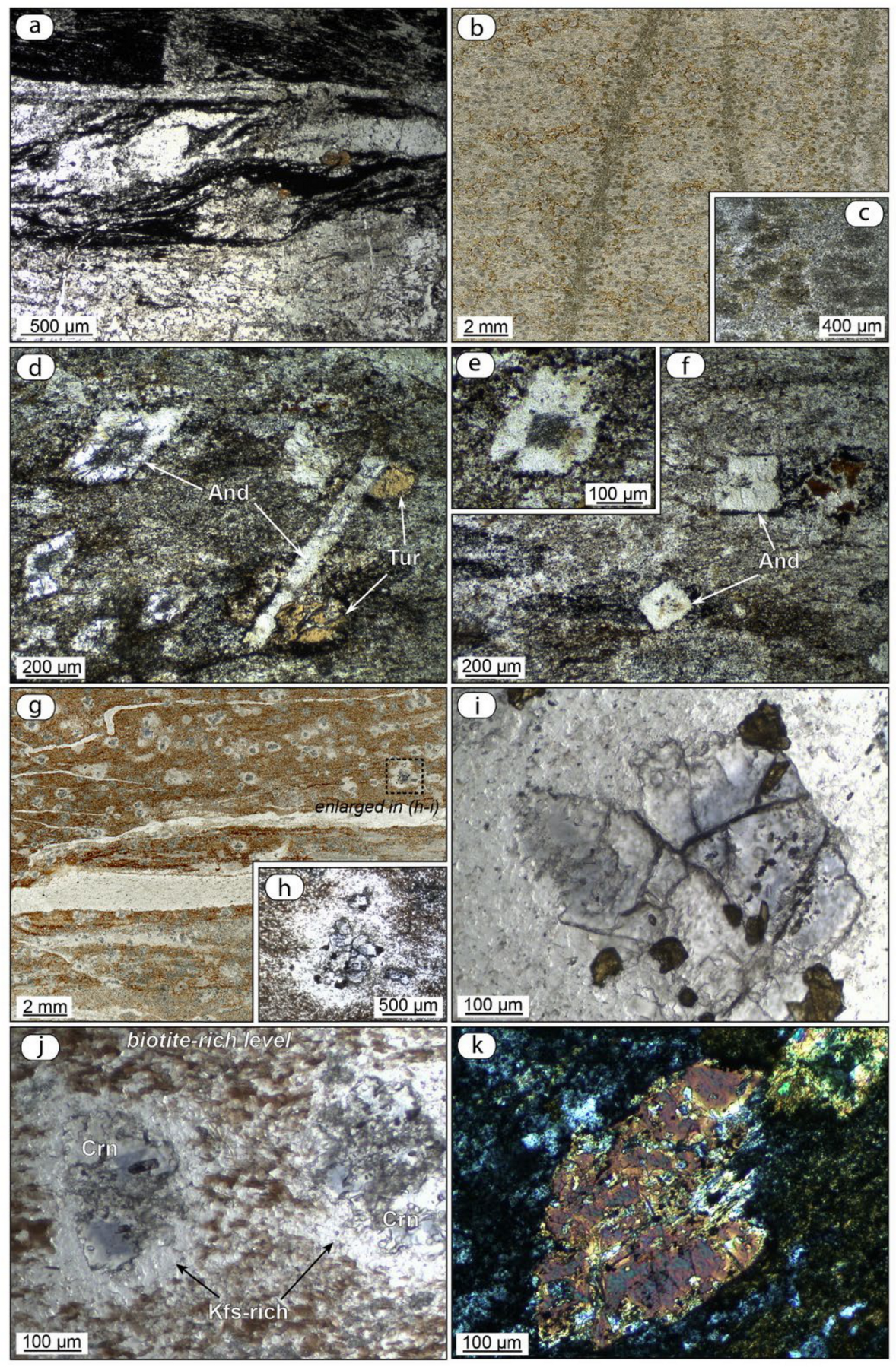
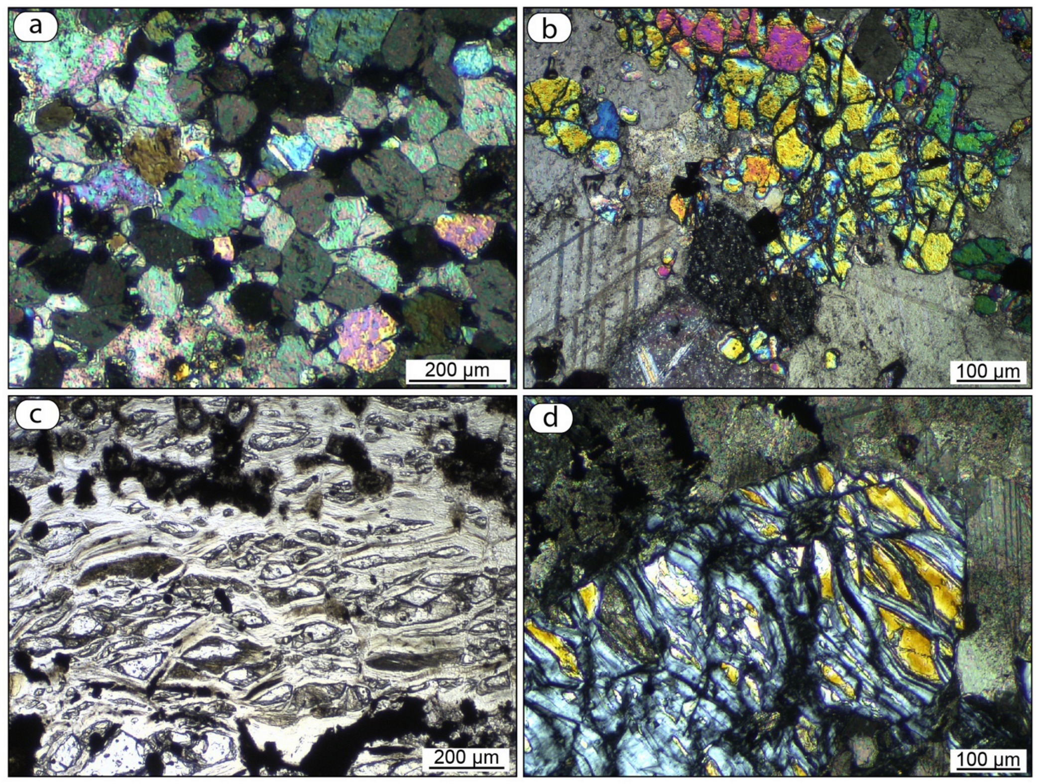
4. The Contact Aureole

The emplacement of the Gavorrano pluton produced LP-metamorphism on the host rocks resulting in a narrow contact aureole with a thickness of 200–300 m [25,26]. LP-metamorphism superimposed on the regional metamorphism which affected the pre-evaporitic metamorphic “basement” mainly represented by the Palaeozoic-Triassic phyllitic-quartzite units (i.e., dominantly pelitic successions), and the late Triassic carbonate rocks, producing hornfelses with different mineral assemblages, as firstly described by [25]. Concerning the pelitic rocks, [25,26] document a mineralogical assemblage made up of quartz + muscovite + K-feldspar + andalusite and chlorite + biotite + cordierite in Mg and Fe-bearing phyllite. Differently, [47] describe quartz + plagioclase + K-feldspar + andalusite and blasts replaced by fine-grained white mica they interpret as relicts of cordierite. [25] also describes corundum and green spinel, replaced by biotite and plagioclase, found within xenoliths collected in the Gavorrano mine. Differently, in the carbonate rocks, calc-silicate hornfels, partially replaced by skarn, shows a mineral assemblage mainly formed by garnet + epidote + spinel + wollastonite + diopside + forsterite + scapolite + quartz + calcite + vesuvianite [25,26]. At depth, the contact between granite and hornfels was described at −50 m, −200 m and −250 m [26,46] and wollastonite + calcite + quartz and diopside + forsterite + calcite mineral assemblages, with local levels enriched of garnet + vesuvianite + scapolite, have been found [46]. In the deepest levels of the Gavorrano mine (−200 m depth b.s.l.), [26] document dolomitic marble characterised by centimetric calcite and dolomite crystals, intimately associated to calc-silicate hornfels. Similarly, at the contact with the monzogranite, the same authors describe 1–2 m thick mineral assemblages consisting of: i) diopside + garnet + dolomite + calcite approaching the hornfels, and ii) epidote + tremolite + diopside + scapolite + calcite + garnet approaching the monzogranite. Diopside + tremolite veins, classified as replacement skarn [103], have also been documented in veins that cut the hornfels; similarly, narrow bands of phlogopite + tremolite (± actinolite) composition have also been described at the boundary between hornfels and skarn. No data are available for the mineralogical assemblage of the pelitic rocks, at the depth where observations were carried out. LP-metamorphism was followed by a subsequent hydrothermal event which produced, among the Fe-ore deposit [26,29,65], the alteration of the forsterite and diopside into serpentine, tremolite, talc, and chlorite, and the formation of veins filled by quartz + adularia + epidote + sulphides± calcite ± albite ± tremolite indicating temperature of about 250–300 °C [26]. Speculation of maximum temperature of about 175 °C was proposed for the last hydrothermal circulation by [104] analysing goethite and clay minerals at the Rigoloccio Mine (Figure 3a), derived from the hydrothermal alteration of the monzogranite and pyrite body.
We have implemented the existing dataset by analysing key samples of pelitic and carbonate hornfels from some key outcrops nearby the Ravi mine (Figure 3a) and from underground. These latter samples have been collected at: (i) the level −50 m b.s.l. of the Gavorrano mine; (ii) samples collected in the mining dump and possibly coming from the level −200 m of the Gavorrano mine. On the whole, our data agree with those reported by the previous Authors and provide additional information on the pelitic hornfels, particularly from the deep part of the Gavorrano mine.
The analysed pelitic and semipelitic rocks grade from spotted schist to hornfels (Figure 7). A compositional layering is generally recognisable being highlighted by an alternation of quartz- and mica-rich levels. In several cases, an intense deformation is observed in the form of serrated microfolds and winged d-porphyroclast (Figure 7a). In the spotted schist, the mineral assemblage is typically made up of quartz + biotite + muscovite + andalusite + tourmaline. Tiny elliptical cloudy spots are observed, probably derived from original cordierite (Figure 7b,c). In the hornfels from the deep level of the Gavorrano mine, muscovite-out conditions were reached as testified by the presence of K-feldspars and locally of corundum. Quartz crystals display variable grains size and are commonly characterised by polygonal shapes. In some cases, quartz shows lobate grain boundaries suggesting that a dynamic recrystallization took place. Biotite flakes increase in abundance from spotted schist to hornfels where they show orange-brown colour when oriented parallel to the lower polarizer. Andalusite porphyroblasts commonly show euhedral habit, with elongated and square diamond shapes (Figure 7d–f). The latter, usually contain the cross-shaped dark inclusion pattern typical of chiastolite (Figure 7d,e) as also described by [25]. Corundum is abundant and well recognisable at microscope scale in the form of spots made up of isolated crystals or aggregates within the biotite-rich levels devoid of quartz (Figure 7g). It shows a polygonal shape and a corona made up of K-feldspar, rare muscovite ± rutile (Figure 7h,j). It often displays a pale blue colour typical of sapphire variety. Tourmaline is zoned with brown to cyan colours being of dravite type and is mostly found within biotite-rich levels (Figure 7k). Among the accessory phases, zircon and opaque minerals are always present, whereas rutile is found in corundum-bearing hornfels.
The analysed carbonate rocks collected in the Gavorrano mine (level—50m b.s.l.) consist of marbles with a variable grain size. In most cases, they contain olivine (Figure 8a,b) without diopside suggesting that they derive from carbonatic-silica-pure protolith. Locally, in the fine-grained type a polygonal fabric of calcite can be recognised, indicating a static recrystallization (Figure 8a). In some cases, olivine-rich levels show diffuse serpentinization, with few olivine relicts still present (Figure 8c,d), justified by [25,26] as the effect of a later hydrothermal fluid flowing through the thermal aureole.
Some considerations can be provided on the peak P-T conditions reached in the thermal aureole. In the pelitic hornfels, recording the maximum temperature in the contact aureole, muscovite-out conditions were reached through the reaction:
Ms + Qtz = And + Kfs + H2O
Alternatively, in silica-poor domains, the genesis of corundum could be promoted by reaction:
Ms = Crn + Kfs + H2O
After muscovite disappearance, corundum could be produced by reaction provided by Pattison and Harte [107]:
2 Bt + 15 Al2SiO5 = 9 Crn + 3 Crd + 2 Kfs + 0.5 H2O
In the analysed samples, there is no evidence for the simultaneous blastesis of corundum and cordierite. Thus, reaction (2) is preferred for the genesis of corundum.
In order to constrain P-T conditions for the contact metamorphism, a look at a simple P-T grid is practical. The diagram in Figure 9, in addition to reaction curves (1) and (2), shows the wet solidus curve for granite and the andalusite—sillimanite equilibrium line. The absence in the hornfels of sillimanite and of microstructures indicative of partial melting indicate that the andalusite-sillimanite equilibrium line and the granite solidus curve were not crossed during the heating phase. On the other hand, the presence of corundum allows to constrain the metamorphic peak beyond reaction (2), within the grey area. A maximum limit for the pressure, provided by the intersection of reaction (2) with the andalusite-sillimanite equilibrium is of c. 170 MPa, corresponding to a temperature of c. 640 °C. At lower pressures, higher temperatures for the thermal peak are possible.
Quantitative estimates of the temperature were attempted by the Ti-in-biotite thermometer by Wu et al. [108]. This was calibrated for pelitic rocks containing a Ti-rich phase such as ilmenite or rutile at pressure higher of 100 MPa, thus being appropriate for the present case. On the basis of 7 biotite analyses of a corundum-bearing hornfels sample (Table A1), a mean value of c. 660 °C was obtained at a pressure of 170 MPa and of c. 650 °C at a pressure of 100 MPa. A check on the compatibility of these numerical results with the P-T extent of the grey area in the diagram of Figure 9, suggests a pressure value lower than c. 150 MPa, corresponding to a depth lower than c. 6 km, assuming an average density of 2650 kg/m3 for the upper crust. However, considering the error of the thermometer, this latter P limit should be verified through more refined petrological methods and/or geological constraints.

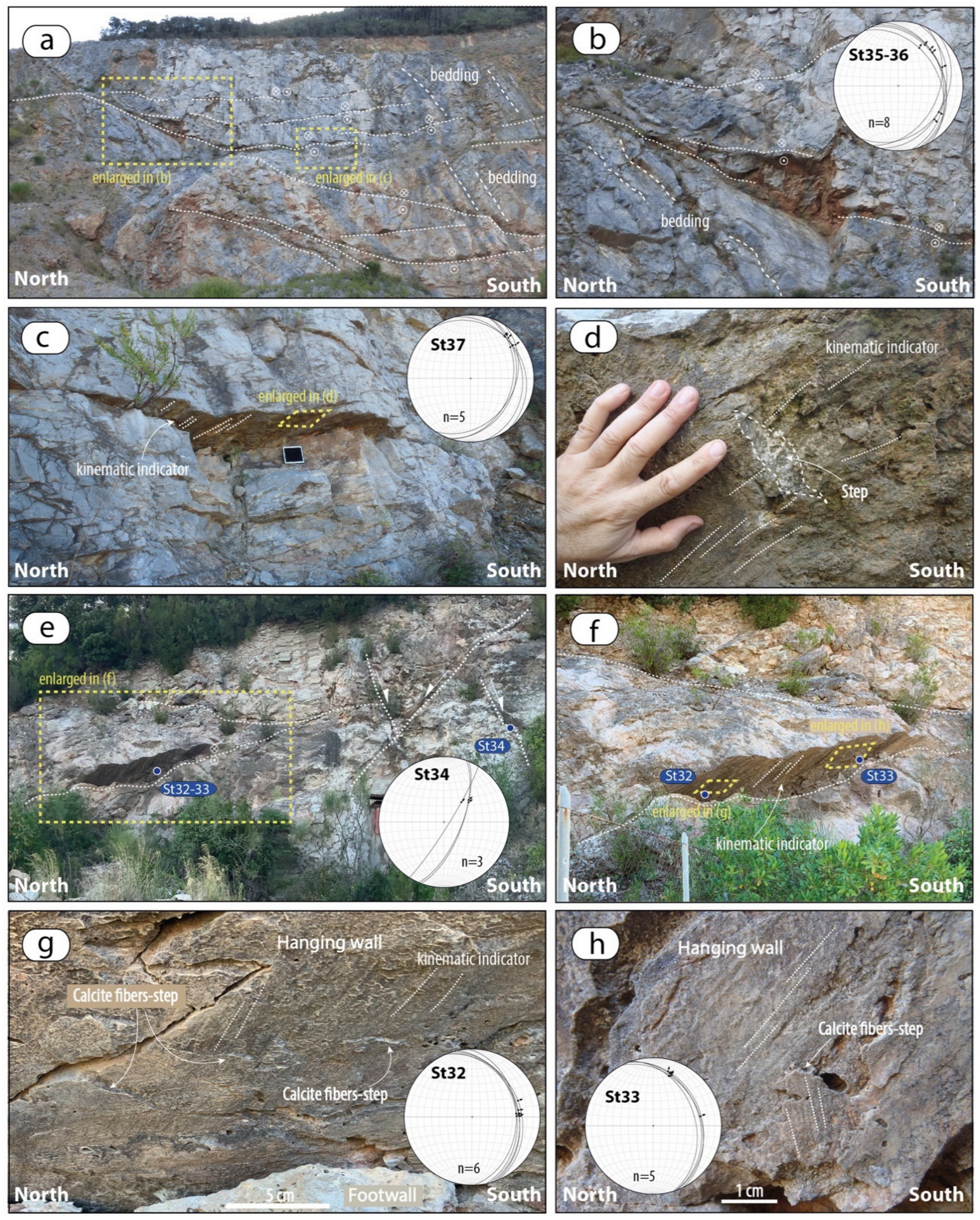
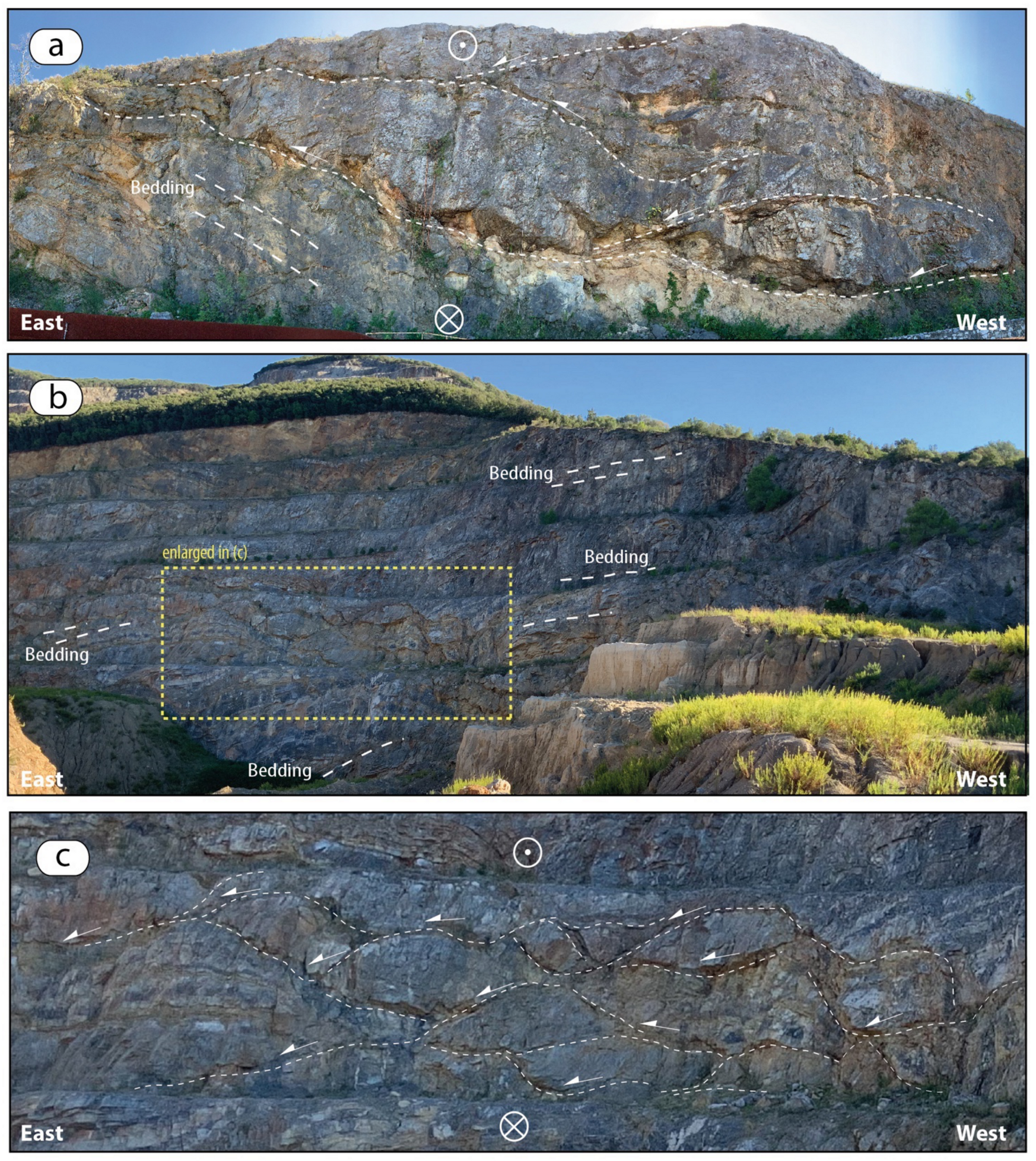
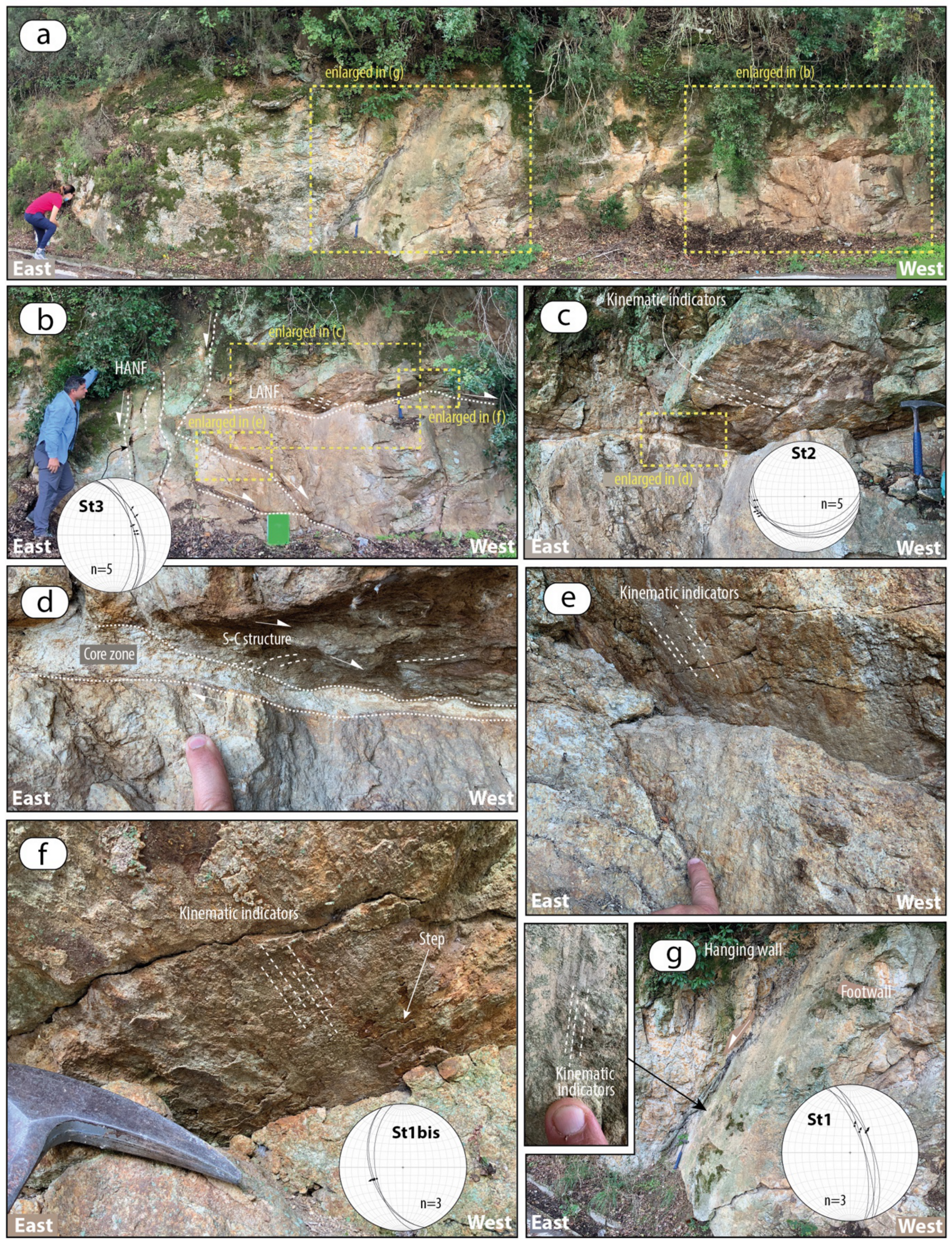
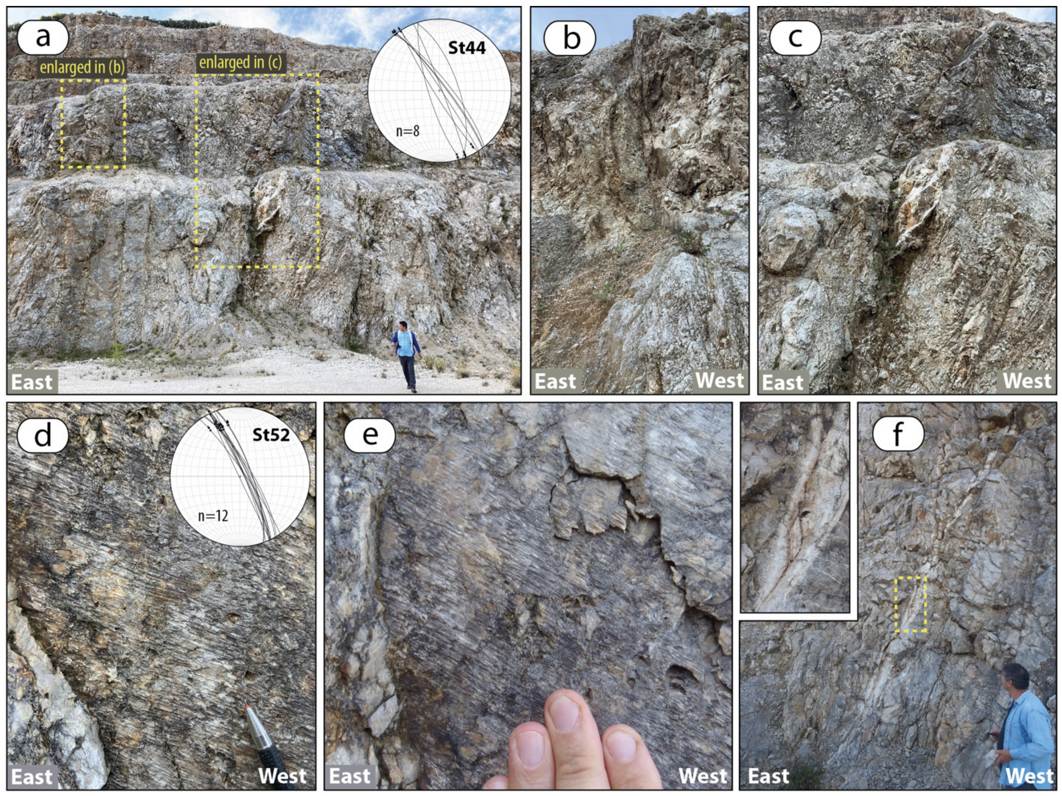
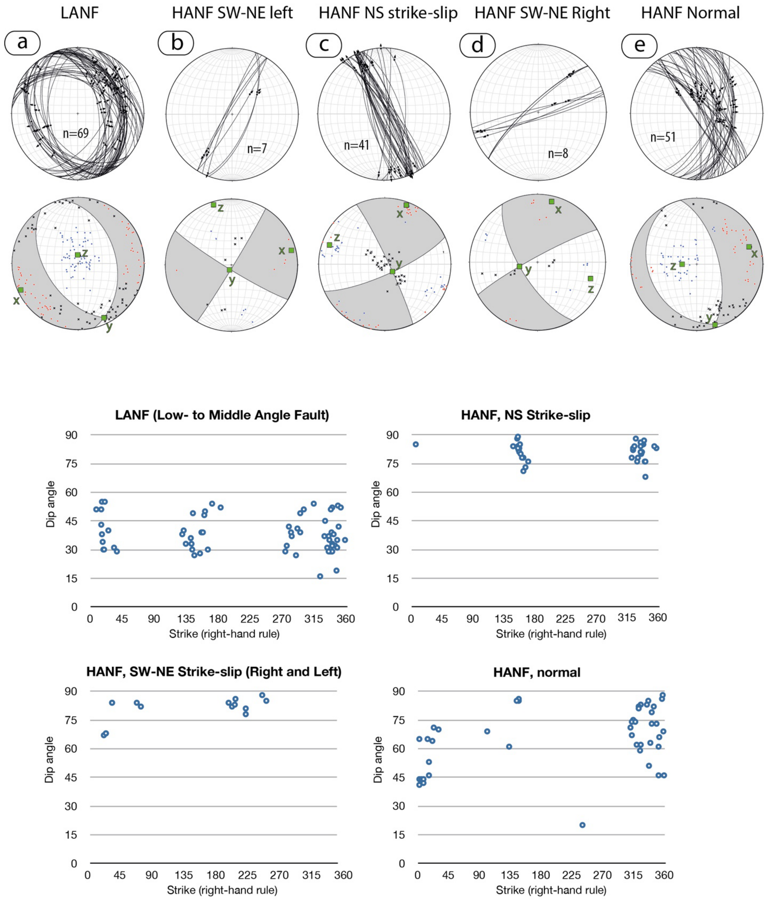
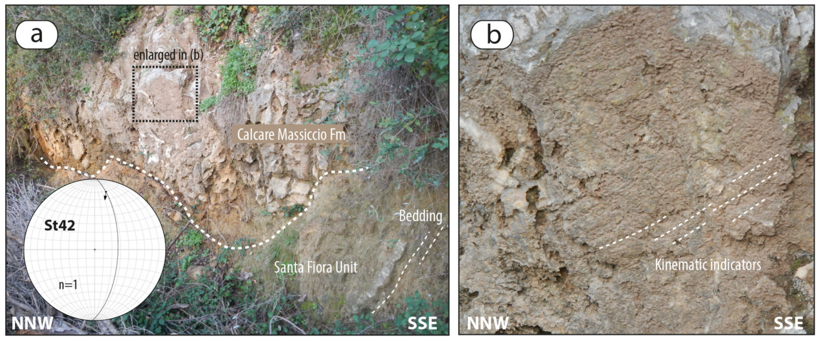
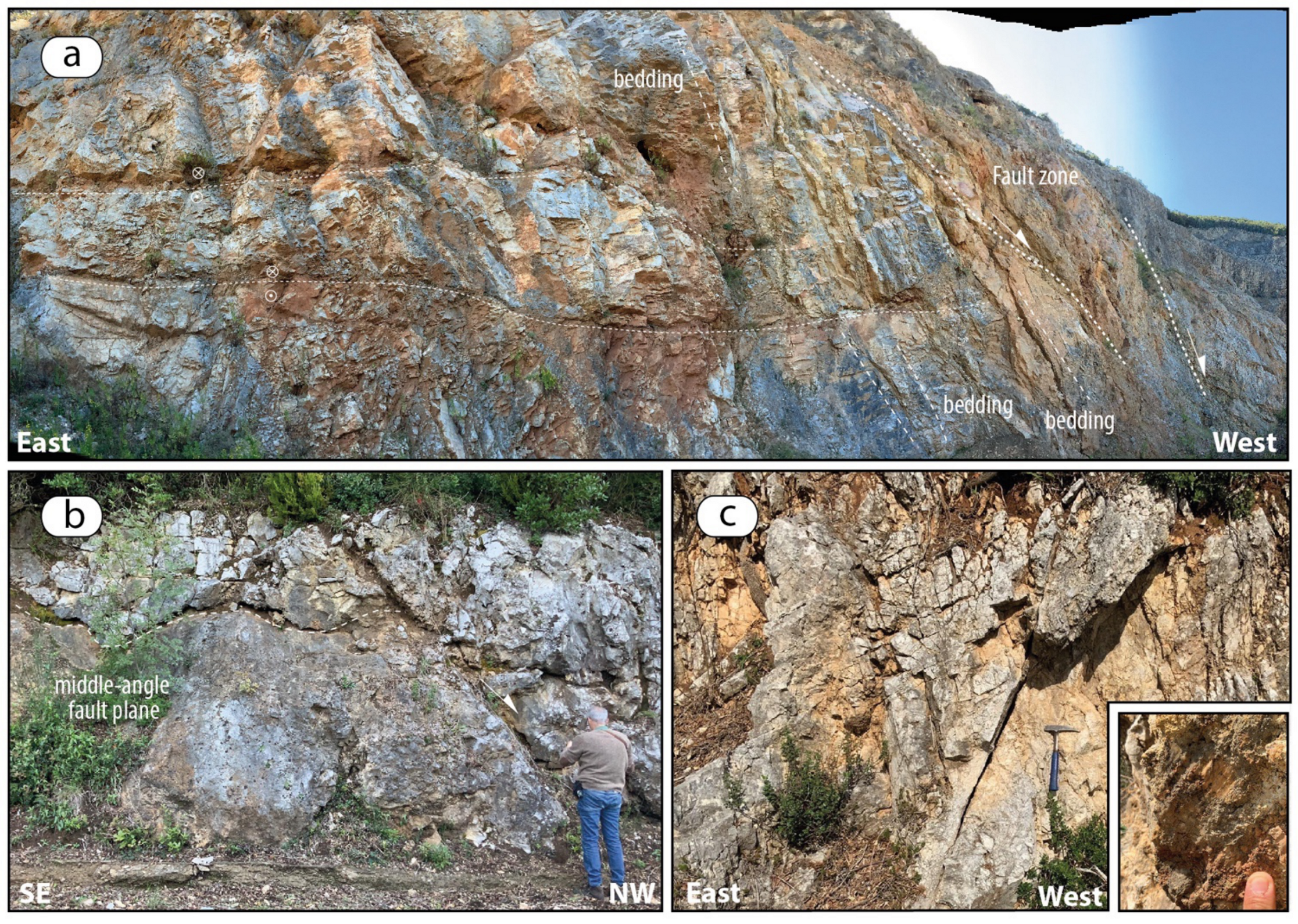
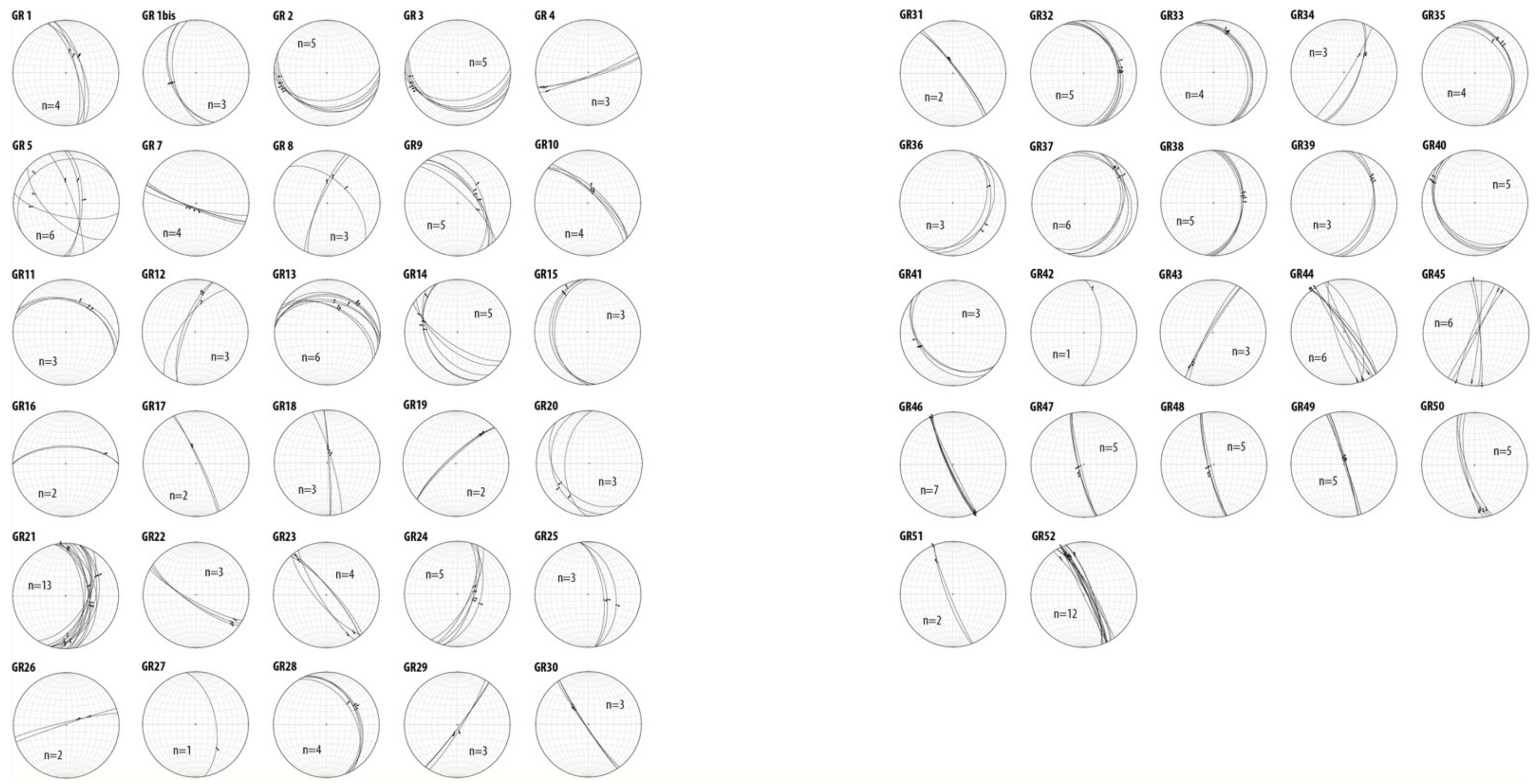
5. Structural and Kinematic Data

The geological setting was already reconstructed by the large amount of mining data as reported in several papers (e.g., [25,26,29,65]). Nevertheless, still contrasting hypotheses are provided by different authors on the tectonic evolution that accompanied the pluton emplacement and its exhumation (cf. [26,35,36,115]).
In order to contribute to this issue, existing mining documents and a new dataset of structural and kinematic data have been integrated. Figure 3a shows the location of the stations where the structural analysis has been carried out. The results are shown in the stereographic diagrams, reported in the Annex 1.
Both cartographic and outcrop-scale evidence highlight superposed faulting events that can be categorized In (i) low- to middle-angle (<50° of dipping value) normal faults, affecting both granite and the carbonate succession; (ii) high angle (>50° of dipping value) strike-slip faults coexisting with the low- to middle-angle normal faults; (iii) high angle normal faults displacing the previous formed structures (Figure 3a,b).
As it regards the low- to middle-angle faults, the best example is the Monticello Fault (Figure 3a and Figure 5), which decouples the monzogranite from the overlying sedimentary cover, by an almost ten-meter thick mineralized cataclastic zone, as it is well documented by the mining data (Figure 5a). Therefore, the consideration of the mining data changes the view of the Monticello Fault, previously interpreted as a high-angle normal fault, parallel to the Gavorrano Fault although dipping in the opposite direction and delimiting the monzogranite to the east [26,29,35,47].
By the new integration of data, the Monticello Fault assumes the role of an already existing fault decoupling the magmatic intrusion from the hosting rocks and contributing to the exhumation of the monzogranite. Such a structure was later affected by high-angle faults to which the Gavorrano Fault belongs (Figure 3a,b). It is worth to note that, on the basis on the mining data form the Ravi mine (located in the southern part of the Monticello fault), Marinelli [25] accounts for a shear zone, separating the magmatic intrusion from the hosting rocks, similarly to what is observed along the Monticello Fault.
Low-angle faults affecting the carbonate succession (Figure 3a and Figure 10), also occur in the hanging wall of the Monticello Fault (Figure 3a). These are well-exposed in the abandoned quarries on the northern slope of the Monte Calvo area and are arranged in sub-parallel and anastomosed segments that define decameters-thick sheared and delaminated volumes with conjugated fault segments forming lozenge-shape geometries and meter-/decameter-scale extensional horses (Figure 11 and Figure 12). Fault segments are characterized by kinematic indicators consisting of calcite fibres and steps, indicating normal, mostly top-to-the E-NE sense of shear (Figure 11, Figure A1). All these data contrast with the kinematic interpretation proposed by [36], although conducted in the same outcrops (cfr. Figure 7a,b in [36]). These authors, in fact, support a top-to-the west reverse kinematics of these faults, notwithstanding the fact that kinematic indicators clearly indicate a normal movement (Figure 11b,f). Furthermore, it is worth to underline that this particular kinematics is in agreement with the data collected in the whole Gavorrano area (Figure A1) and with the geometrical setting of the low-angle faults, as visible in the quarry exposures (Figure 12).
Low-angle faults affecting the monzogranite (Figure 13a,b) have also been recognized. Here, these show striated slip-surfaces (Figure 13c) bounded by a centimeter-thick core zone with ultra-comminuted grains (Figure 13d) and centimeters-thick level of foliated monzogranite, showing s-c structures, with a top-to-the west sense of shear (Figure 13e,f). Although faults exposure in granite are limited, their setting accounts for a lozenge-shaped geometry (Figure 13b), thus explaining the occurrence of both top to E-ENE (dominant) and top to W-WSW sense of shear on their slip planes, respectively.
Concerning the high angle faults, N-S and SW-NE strike-slip faults occur in the whole area (Figure 3a). The best exposures (especially for the N-S striking faults) were recognized in the quarries, north of the Monte Calvo (Figure 10) and in the western part of the study area (i.e., Palaie Fault, Figure 3a).
In the abandoned quarries, these faults define decameters-thick vertical brittle shear zones (Figure 14) formed by sub-parallel and conjugate fault planes (Figure 14a–c), surrounded by well-developed damage zones. Left-lateral strike to oblique-slip kinematics is then suggested by indicators locally preserved on the slip-surfaces and consisting of calcite slicken-fibres and steps (Figure 14d,e). In some cases, syn-kinematic cm- to dm-thick banded calcite veins formed along the fault planes, or in extensional jogs (Figure 14f).
This attests the role of such faults in controlling the hydrothermal fluid paths from the late magmatic events onwards, at least. This is in fact attested by the several S-N and SW-NE oriented microgranite dykes intruding both the monzogranite and the hosting rocks in fault zones, as documented in the outcrops (Figure 15) and by the underground mining data (Figure 4). Thus, a local strike-slip regime is supposed to have controlled the deformation in the Gavorrano area, and probably the pluton emplacement. Nevertheless, although the interplay between the low-angle normal faults and the S-N to SW-NE striking strike-slip faults has not been directly documented in the field, it is reasonable to assume that the transcurrent faults were contemporaneously active with the low-angle normal faults, since both fault systems are affected by syn-tectonic hydrothermal circulation. Their contemporaneity is also confirmed by the inversion of the kinematic data collected on fault-slip surfaces of both low-angle normal faults and strike-slip faults: it highlights a strong kinematic compatibility, as shown by the orientation of the main kinematic axes (Figure 16a–c). We can therefore assume that these faults were active under a common stress field: in this view, the low-angle normal faults developed as a consequence of the crustal thinning, having triggered magmatism and favoured the development of SW-NE striking km-thick sub-vertical brittle shear zone (i.e., transfer zone: [116,117,118]) of which the Gavorrano area is a part.
In the context of the deformation induced by a transfer zone, the N-S striking left-lateral and SW-NE striking right-lateral strike-slip faults are thus framed in the same setting, as indicated by their kinematic compatibility (Figure 16c,d). Consequently, those are interpreted as minor faults linking the SW-NE striking main structures, in a common left-lateral strike-slip shear zone.
Concluding, we can depict a tectonic evolution where low-angle normal faults and strike-slip faults (N-S striking left-lateral strike-slip, SW-NE striking left- and right-lateral strike-slip faults) coexisted during the emplacement and exhumation of the monzogranite, as sketched in the conceptual model of Figure 17a,b.
The Palaie Fault (Figure 3a) has been described by several authors as a strike-slip fault [35] or a transpressive fault, by the kinematics reconstructed in a single outcrop [36]. Our data (Figure 18) highlight that what today is recognizable along the western slope of the Monte Calvo is the result of two superposed faulting events, at least: strike-slip fault segments are in fact preserved within lithons delimited by sub-parallel west-dipping normal faults (Figure 3a). In other words, the western slope of the Monte Calvo is delimited by a normal fault system partly reactivating and dissecting older N-S striking left-lateral strike-slip faults, thus determining lithons of which original attitude is reasonably modified. This can explain the singularity of the Palaie Fault, the single structure with visible kinematic indicators contrasting the general framework.
High angle normal faults, NNW-SSE and N-S striking are the youngest structures. These dissect the previous formed low-angle faults (Figure 19a,b) and are characterized by oblique-slip to normal movements (Figure 19c). Fault zones are with meters-thick damage zones (Figure 19a) where well-organized minor fractures affect both their hanging wall and footwall (Figure 19c). Kinematic indicators mainly consist of groove and mechanical striations developed on the fault surfaces.
Inversion of kinematics data collected on the normal faults (Figure 16e) show a kinematic compatibility with the low-angle normal faults (Figure 16a), thus supporting a stable E-NE trending extensional regime from the emplacement of the monzogranite until its exhumation (Figure 17c).

6. Conclusive Remarks

On the basis of the new dataset integrated with the pre-existing data we can state the following points:
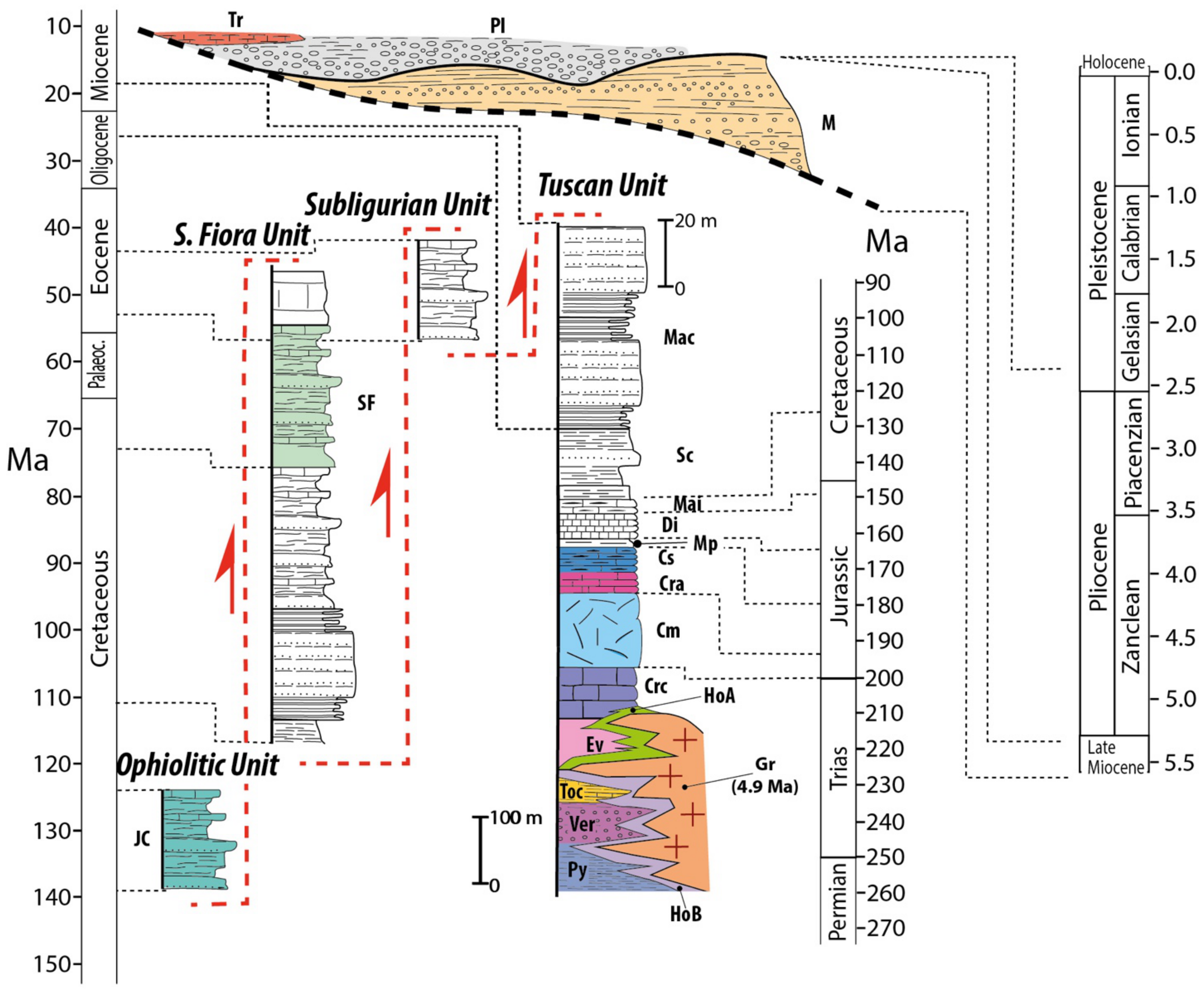
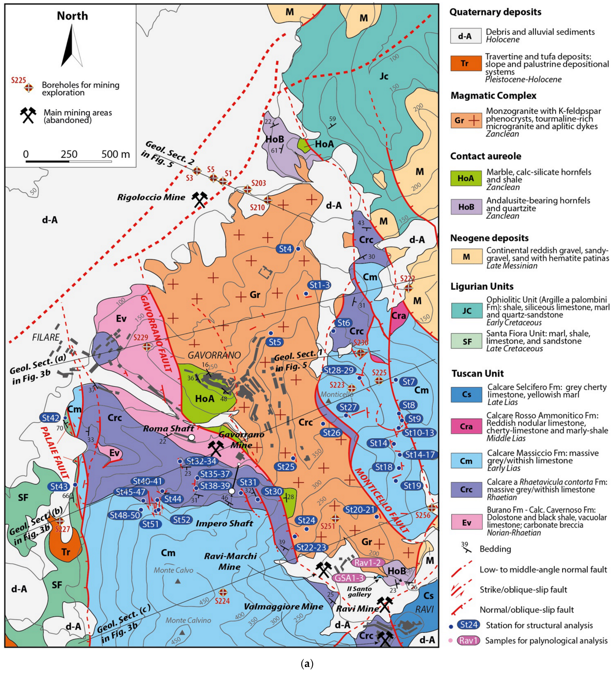
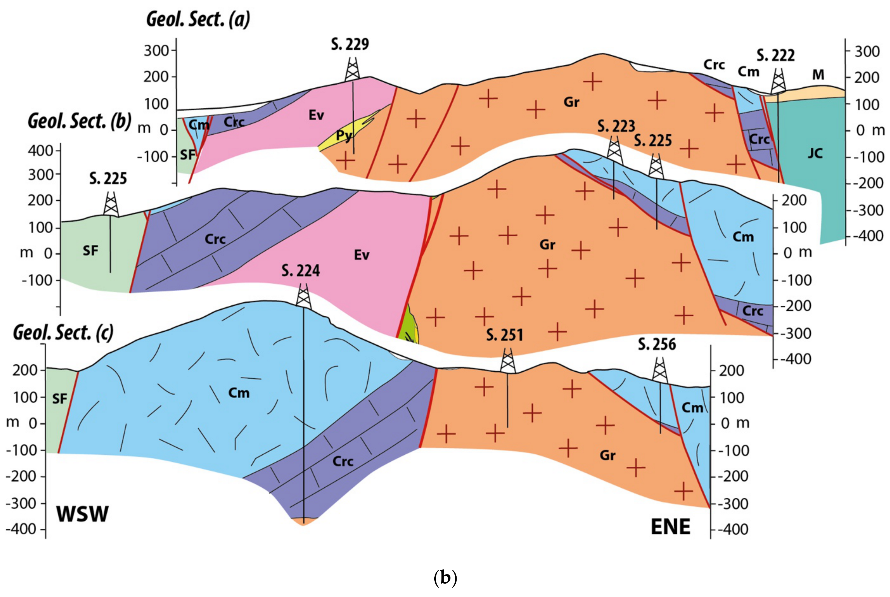
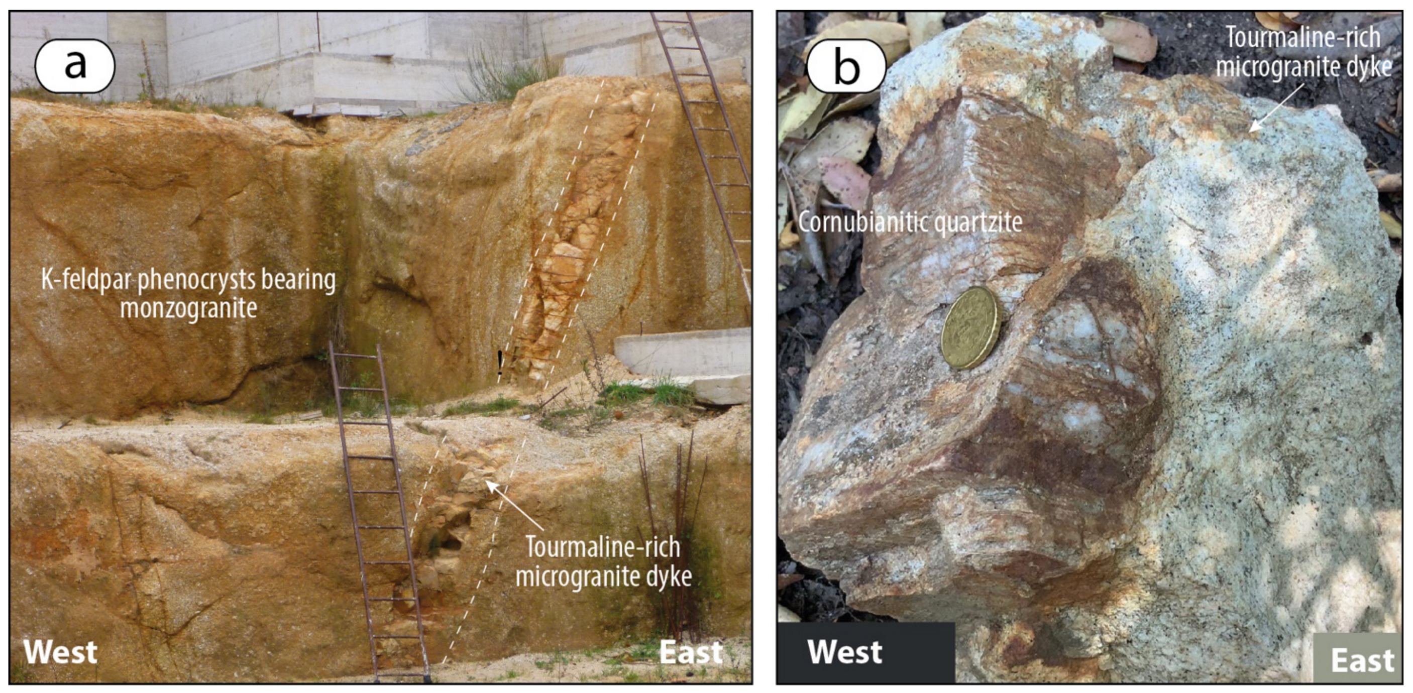
  • The laccolithic monzongranite emplaced within the upper part of the Tuscan metamorphic succession, at the base of the Late Triassic carbonate succession. The exposed contact aureole at north of Ravi village is referred to the phyllitic-quartzite succession, similar to part of that one exposed at north of the Gavorrano village, underlying the metasandstone and quartz-metaconglomerate of the Triassic Verrucano Group. The succession exposed in the Gavorrano village and neighbourhood is referred to a transitional succession (i.e., Tocchi Fm) interposed between the Verrucano and late Triassic evaporite. The Palaeozoic succession hosting the monzogranite has a middle-late Permian age and can be referred to the coeval successions documented in the surroundings (e.g., Poggio al Carpino Fm, Filladi di Boccheggiano and Quarziti del Torrente Mersino formations). The decimetres-thick quartz-metasandstone levels interbedded within black phyllite, recognised in the Il Santo gallery, make this succession similar to the Poggio al Carpino Fm. On the contrary, the dominant black phyllite exposed at surface better corresponds to the Filladi di Boccheggiano and Quarziti del Torrente Mersino formations.
  • The thermo-metamorphic paragenesis and Ti-in-biotite geothermometer point to a peak Temperature of c. 660 °C at a depth probably lower than 6 km. Dynamic recrystallisation of LP paragenesis suggests a syn-kinematic evolution of the contact aureole, in agreement with the active tectonic setting that assisted the magma emplacement, cooling and exhumation.
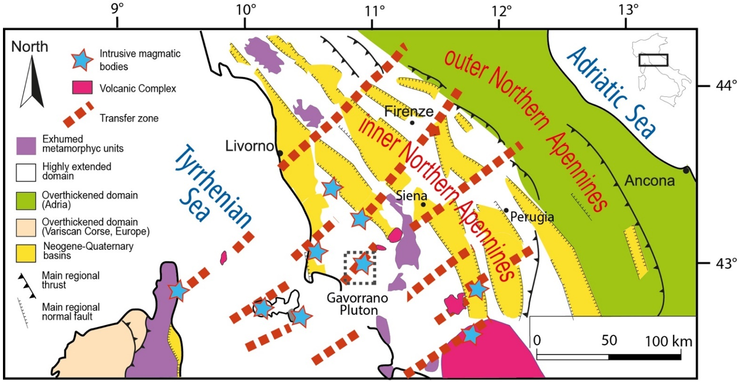
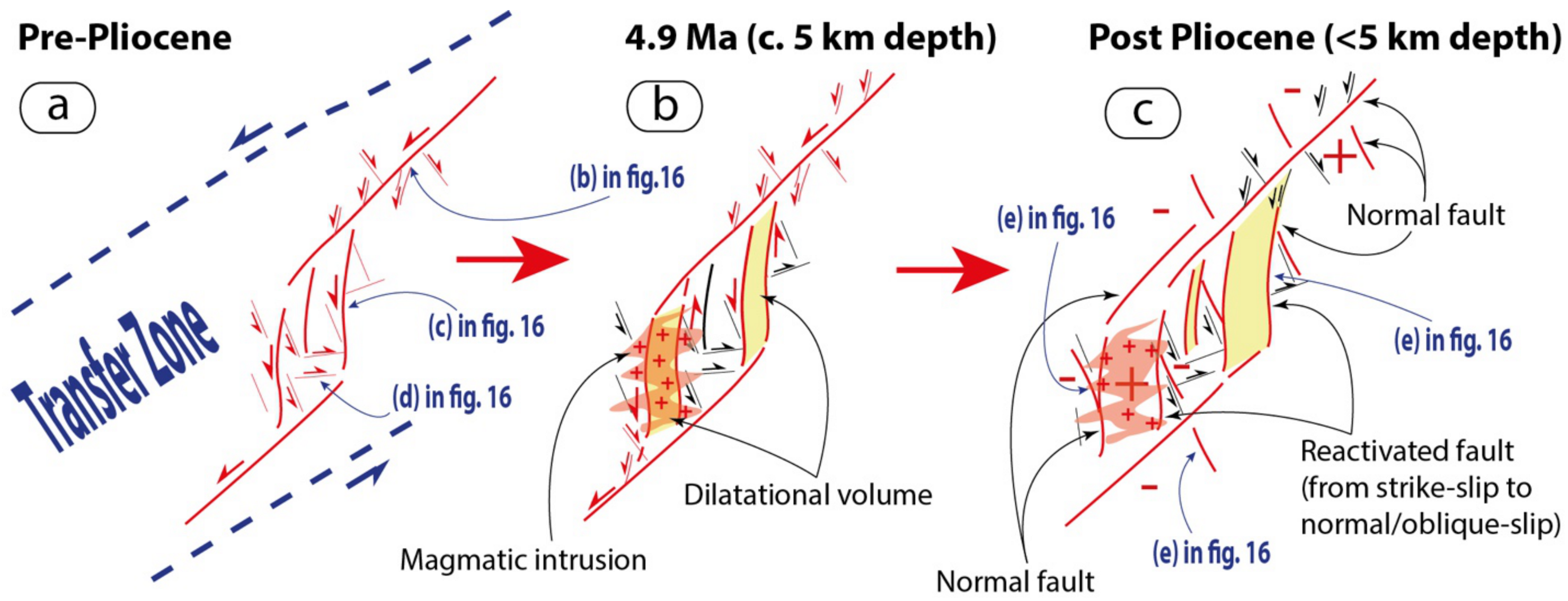
  • We do not confirm the occurrence of regional and/or cartographic scale reverse faults, or thrust-related roof-anticline triggering the magma emplacement and hosting the magmatic intrusion, since those previously proposed interpretations contrast with field data evidence. The pluton emplacement was coeval with coexisting strike-slip and extensional tectonics that continued also after the magma cooling and produced the exhumation of the magmatic system and of its contact aureole. The tectonic setting did not change through time: strike-slip and normal faults coexisted at least since the early Pliocene (age of the monzogranite emplacement). The Gavorrano pluton emplaced within a SW-NE trending sub-vertical strike-slip brittle shear zone (i.e., transfer zone) that accompanied the development of low-to middle-angle normal faults formed in a E-NE trending extensional setting. SW-NE striking strike-slip faults were mainly linked by NS striking strike-slip faults in releasing step-over zones, favouring the development of sub-vertical dilatational volumes with enough permeability to channel the magma from the deeper to upper crustal levels.

Author Contributions

Conceptualization, A.B.; methodology, A.B., A.C. (Alfredo Caggianelli), D.L., A.S., and M.Z.; software, A.B., A.C. (Alfredo Caggianelli), D.L., and M.Z.; validation, A.B. and D.L.; formal analysis, A.B., A.C. (Alfredo Caggianelli), D.L., A.S., and M.Z.; investigation, A.B., E.C., A.C. (Alfredo Caggianelli), D.L., and M.Z.; data curation, A.B., E.B., E.C., A.C. (Alfredo Caggianelli), A.C. (Alessandra Casini), D.L., A.S., and M.Z.; writing—A.B.; writing—review and editing, A.B., E.C., A.C. (Alfredo Caggianelli), A.C. (Alessandra Casini), D.L., A.S., and M.Z.; visualization, A.B.; project administration, A.B. and A.C. (Alessandra Casini); funding acquisition, A.B., D.L., and A.C. (Alessandra Casini). All authors have read and agreed to the published version of the manuscript.

Funding

This research was funded by: (1) Department of Physics and Geology (University of Perugia) ‘REDAB—REDiscovering the Apennine Basement: a multidisciplinary correlation among the Northern Apennine Upper Paleozoic–Triassic successions (CAPEZBASE2017) (Amalia Spina and Enrico Capezzuoli); (2) European Community’s Seventh Framework Programme under grant agreement No. 608553 (Project IMAGE) (Domenico Liotta, Andrea Brogi, Martina Zucchi); (3) FFABR grants (financial support for the base-research activity) from the MIUR (Ministry of Education and University) (Andrea Brogi). (4) Department of Earth and Geoenvironmental Sciences (University of Bari), University Project: Cooling of intra-crustal magmatic bodies and geothermal fluids circulation: comparison between late Hercinian and Plio-Quaternary granitoids from Calabria and southern Tuscany (Alfredo Caggianelli).

Informed Consent Statement

Informed consent was obtained from all subjects involved in the study.

Acknowledgments

We are indebted with Andrea Dini who supported us in discussing the evolution of the magmatic system and geological setting of the study area. We are grateful to the two anonymous reviewers for their helpful comments and valuable suggestions.

Conflicts of Interest

The authors declare no conflict of interest.

Appendix A

Figure A1. Structural stations: fault and striae from data collected on the indicated structural stations. Their location is indicated in the Figure 3a (lower hemisphere, equiareal diagram).
Geosciences 11 00124 g0a1
Table A1. Biotite analyses of corundum-bearing hornfels used for the application of the Ti-in-biotite geothermometer by [109]. Mineral formulae, calculated according to the method by [119].
Bt 42Bt 43Bt 44Bt 45Bt 46Bt 47Bt 48
SiO233.2533.1934.2434.9833.6334.6435.57
TiO23.573.583.363.693.573.573.60
Al2O320.7820.5820.1120.6420.8620.9621.73
FeO17.4217.4217.9817.9117.3917.2715.88
MnO0.340.270.440.39 0.29
MgO8.368.368.518.798.188.628.87
Na2O0.180.23 0.180.320.300.18
K2O9.9210.1710.1010.2110.1410.089.93
Tot93.8293.8094.7496.7994.0995.7395.76
Si2.572.572.622.622.592.612.64
Ti0.210.210.190.210.210.200.20
AlIV1.431.431.381.381.411.391.36
AlVI0.460.450.440.440.480.470.55
Fe1.121.131.151.121.121.090.99
Mn0.020.020.030.02 0.02
Mg0.960.960.970.980.940.970.98
Na0.030.04 0.030.050.040.03
K0.981.000.990.970.990.970.94
∑cat7.787.817.777.777.797.767.69
∑O11.0011.0111.0011.0111.0211.0011.00
Fe3+0.030.060.040.050.110.100.16
Fe2+1.091.071.111.071.010.990.83
T, °C *657657641652668659679
* Temperature estimate by Ti-in-biotite geothermometer [109] at P = 150 MPa.

References

  1. Brunet, C.; Monié, P.; Jolivet, L.; Cadet, J.P. Migration of compression and extension in the Tyrrhenian Sea, insights from 40Ar/39Ar ages on micas along a transect from Corsica to Tuscany. Tectonophysics 2000, 321, 127–155. [Google Scholar] [CrossRef]
  2. Rossetti, F.; Faccenna, C.; Jolivet, L.; Goffé, B.; Funiciello, R. Structural signature and exhumation P-T–t paths of the blueschist units exposed in the interior of the Northern Apennine chain, tectonic implication. Boll. Soc. Geol. It. 2002, 1, 829–842. [Google Scholar]
  3. Bianco, C.; Godard, G.; Halton, A.; Brogi, A.; Liotta, D.; Caggianelli, A. The lawsonite-glaucophane blueschists of Elba Island (Italy). Lithos 2019, 348–349. [Google Scholar] [CrossRef]
  4. Carmignani, L.; Decandia, F.A.; Disperati, L.; Fantozzi, P.L.; Lazzarotto, A.; Liotta, D.; Oggiano, G. Relationships between the Tertiary structural evolution of the Sardinia-Corsica-Provencal Domain and the northern Apennines. Terra Nova 1995, 7, 128–137. [Google Scholar] [CrossRef]
  5. Bartole, R. The North Tyrrhenian-Northern Apennines post- collisional system: Constraints for a geodynamic model. Terra Nova 1995, 7, 7–30. [Google Scholar] [CrossRef]
  6. Calcagnile, G.; Panza, G.F. The main characteristics of the lithosphere–asthenosphere system in Italy and surrounding regions. Pure Appl. Geophys. 1980, 119, 865–879. [Google Scholar] [CrossRef]
  7. Locardi, E.; Nicolich, R. Geodinamica del Tirreno e dell’Appennino centro-meridionale: La nuova carta della Moho. Mem. Soc. Geol. It. 1992, 41, 121–140. [Google Scholar]
  8. Di Stefano, R.; Bianchi, I.; Ciaccio, M.G.; Carrara, G.; Kissling, E. Three-dimensional Moho topography in Italy: New constraints from receiver functions and controlled source seismology. Geochem. Geophys. Geosyst. 2011, 12, 1–15. [Google Scholar] [CrossRef]
  9. Marinelli, G. Genèse des magmas du volcanisme Plio-Quaternaire des Apennines. Geol. Rdsch. 1967, 57, 127–141. [Google Scholar] [CrossRef]
  10. Peccerillo, A. Plio-Quaternary magmatism in Italy. Episodes 2003, 26, 222–226. [Google Scholar] [CrossRef]
  11. Elter, P.; Giglia, G.; Tongiorgi, M.; Trevisan, L. Tensional and compressional areas in the recent (Tortonian to Present) evolution of north Apennines. Boll. Geofis. Teor. Appl. 1975, 17, 3–18. [Google Scholar]
  12. Serri, G.; Innocenti, F.; Manetti, P. Geochemical and petrological evidence of the subduction of delaminated Adriatic continental lithosphere in the genesis of the Neogene-Quaternary magmatism of central Italy. Tectonophysics 1993, 223, 117–214. [Google Scholar] [CrossRef]
  13. Carmignani, L.; Decandia, F.A.; Disperati, L.; Fantozzi, P.L.; Kligfield, R.; Lazzarotto, A.; Liotta, D.; Meccheri, M. Inner northern Apennines. In Anatomy of an Orogen: The Apennines and Adjacent Mediterranean Basins; Vai, G.B., Martini, I.P., Eds.; Kluwer Academic: Dordrecht, The Netherlands, 2001; pp. 197–213. [Google Scholar]
  14. Gianelli, G.; Puxeddu, M.; Batini, F.; Bertini, G.; Dini, I.; Pandeli, E.; Nicolich, R. Geological model of a young volcano-plutonic system: The geothermal region of Monte Amiata (Tuscany, Italy). Geothermics 1988, 17, 719–734. [Google Scholar] [CrossRef]
  15. Dini, A.; Gianelli, G.; Puxeddu, M.; Ruggieri, G. Origin and evolution of Pliocene-Pleistocene granites from the Larderello geothermal field (Tuscan Magmatic Province, Italy). Lithos 2005, 81, 1–31. [Google Scholar] [CrossRef]
  16. Brogi, A.; Lazzarotto, A.; Liotta, D.; Ranalli, G. Crustal structures in the geothermal areas of southern Tuscany (Italy): Insights from the CROP 18 deep seismic reflection. J. Volcanol. Geotherm. Res. 2005, 148, 60–80. [Google Scholar] [CrossRef]
  17. Gola, G.; Bertini, G.; Bonini, M.; Botteghi, S.; Brogi, A.; De Franco, R.; Dini, A.; Donato, A.; Gianelli, G.; Liotta, D.; et al. Data integration and conceptual modelling of the Larderello geothermal area, Italy. Energy Proc. 2017, 125, 300–309. [Google Scholar] [CrossRef]
  18. Rochira, F.; Caggianelli, A.; De Lorenzo, S. Regional thermo-rheological field related to granite emplacement in the upper crust: Implications for the Larderello area (Tuscany, Italy). Geodin. Acta 2018, 30, 225–240. [Google Scholar] [CrossRef] [Green Version]
  19. Della Vedova, B.; Bellani, S.; Pellis, G.; Squarci, P. Deep temperatures and surface heat flow distribution. In Anatomy of an Orogen: The Apennines and Adjacent Mediterranean Basins; Vai, G.B., Martini, I.P., Eds.; Kluwer Academic: Dordrecht, The Netherlands, 2001; pp. 65–76. [Google Scholar]
  20. Brogi, A. Kinematics and geometry of Miocene low-angle detachments and exhumation of the metamorphic units in the hinterland of the Northern Apennines (Italy). J. Struct. Geol. 2008, 30, 2–20. [Google Scholar] [CrossRef]
  21. Liotta, D.; Brogi, A. Pliocene-Quaternary fault kinematics in the Larderello geothermal area (Italy): Insights for the interpretation of the present stress field. Geothermics 2020, 83, 101714. [Google Scholar] [CrossRef]
  22. Gianelli, G.; Manzella, A.; Puxeddu, M. Crustal models of the geothermal areas of Southern Tuscany. Tectonophysics 1997, 281, 221–239. [Google Scholar] [CrossRef]
  23. Batini, F.; Brogi, A.; Lazzarotto, A.; Liotta, D.; Pandeli, E. Geological features of the Larderello–Travale and Mt. Amiata geothermal areas (southern Tuscany, Italy). Episodes 2003, 26, 239–244. [Google Scholar] [CrossRef]
  24. Dallmeyer, R.D.; Liotta, D. Extension, uplift of rocks cooling ages in thinned continental provinces: The Larderello geothermal area (inner Northern Apennines, Italy). Geol. Mag. 1998, 135, 193–202. [Google Scholar] [CrossRef]
  25. Marinelli, G. L’intrusione terziaria di Gavorrano. Atti. Soc. Tosc. Sci. Nat. 1961, 68, 117–194. [Google Scholar]
  26. Dallegno, A.; Gianelli, G.; Lattanzi, P.; Tanelli, G. Pyrite deposits of the Gavorrano area, Grosseto. Atti. Soc. Tosc. Sci. Nat. Mem. 1979, 86, 127–165. [Google Scholar]
  27. Borsi, S.; Ferrara, G.; Tongiorgi, E. Determinazione con il metodo K/Ar della età delle rocce magmatiche della Toscana. Boll. Soc. Geol. It. 1967, 86, 403–410. [Google Scholar]
  28. Serri, G.; Innocenti, F.; Manetti, P. Magmatism from Mesozoic to present: Petrogenesis, time-space distribution and geodynamic implications. In Anatomy of an Orogen: The Apennines and Adjacent Mediterranean Basins; Vai, G.B., Martini, I.P., Eds.; Kluwer Academic: Dordrecht, The Netherlands, 2001; pp. 77–103. [Google Scholar]
  29. Arisi Rota, F.; Vighi, L. Le mineralizzazioni a pirite ed a solfuri misti. Rend. Soc. Ital. Mineral. Petrol. 1971, 27, 370–420. [Google Scholar]
  30. Lotti, B. Sulla geologia del Gruppo di Gavorrano. Boll. R. Com. Geol. Ital. 1877, 8, 53–63. [Google Scholar]
  31. Bencini, A.; Duchi, V.; Minissale, A.; Tanelli, G. Distribuzione di alcuni elementi metallici nelle rocce intrusive e carbonatiche associate alle mineralizzazioni a pirite di Gavorrano (Grosseto). Rend. Soc. Ital. Mineral. Petrol. 1980, 36, 599–609. [Google Scholar]
  32. Cocozza, T.; Lazzarotto, A.; Vai, G.B. Flysch e molassa ercinici del Torrente Farma. Boll. Soc. Geol. It. 1974, 93, 115–128. [Google Scholar]
  33. Bagnoli, G.; Tongiorgi, M. The Tuscan Paleozoic: A critical review. In Report on the Tuscan Paleozoic Basement; Tongiorgi, M., Ed.; Consiglio Nazionale delle Ricerche: Rome, Italy, 1978; pp. 9–26. [Google Scholar]
  34. Musumeci, G.; Mazzarini, F.; Corti, G.; Barsella, M.; Montanari, D. Magma emplacement in a thrust ramp anticline: The Gavorrano Granite (northern Apennines, Italy). Tectonics 2005, 24, 1–17. [Google Scholar] [CrossRef]
  35. Rossetti, F.; Faccenna, C.; Funiciello, R.; Pascucci, V.; Pietrini, M.; Sandrelli, F. Neogene strike-slip faulting and pluton emplacement in the colline metallifere region (Southern Tuscany, Italy): The Gavorrano-Capanne Vecchie area. Boll. Soc. Geol. It. 2001, 120, 15–30. [Google Scholar]
  36. Musumeci, G.; Mazzarini, F.; Barsella, M. Pliocene crustal shortening on the Tyrrhenian side of the northern Apennines: Evidence from the Gavorrano antiform (southern Tuscany, Italy). J. Geol. Soc. Lond. 2008, 165, 105–114. [Google Scholar] [CrossRef] [Green Version]
  37. Sani, F.; Bonini, M.; Cerrina Feroni, A.; Mazzarini, F.; Moratti, G.; Musumeci, G.; Corti, G.; Iatta, F.; Ellero, A. Messinian-Early Pliocene crustal shortening along the Tyrrhenian margin of Tuscany, Italy. Ital. J. Geosci. 2009, 128, 593–604. [Google Scholar] [CrossRef]
  38. Montanari, D.; Corti, G.; Sani, F.; Del Ventisette, C.; Bonini, M.; Moratti, G. Experimental investigation on granite emplacement during shortening. Tectonophysics 2010, 484, 147–155. [Google Scholar] [CrossRef]
  39. Lotti, B. I Depositi Minerari Metalliferi; Ind. Min.: Roma, Italy, 1928; p. 236. [Google Scholar]
  40. Santi, G. Viaggio Terzo per le Due Provincie Senesi che Forma il Seguito del Viaggio al Montamiata; Ranieri Prosperi Stamp: Pisa, Italy, 1806; 182p. [Google Scholar]
  41. Savi, P.; Meneghini, G. Considerazioni sulla geologia stratigrafica della Toscana. In Memorie Sulla Struttura Geologica delle Alpi, degli Appennini e dei Carpazi; Sir Murchison, R.E., Ed.; Stamperia Granducale: Firenze, Italy, 1851; pp. 279–522. [Google Scholar]
  42. Lotti, B. Sull’età e origine dei graniti toscani. Boll. R. Com. Geol. It. 1886, 1–15. [Google Scholar]
  43. Lotti, B. Sul giacimento di pirite di Gavorrano in Toscana. Rass. Min. 1901, 1–8, 116. [Google Scholar]
  44. Marocchi, E. Studio sul granito di Gavorrano. Atti. Soc. Tosc. Sco Nat. Mem. 1897, 15, 171–187. [Google Scholar]
  45. Martelli, A. Ricerche petrografiche e chimiche sulle formazioni granitiche di Gavorrano. Atti. R. Acc. Lincei Rend. 1909, 18, 1–7. [Google Scholar]
  46. Barberi, F.; Innocenti, F.; Ricci, C.A. Il magmatismo. Rend. Soc. Ital. Mineral. Petral. 1971, 27, 169–210. [Google Scholar]
  47. Mazzarini, F.; Corti, G.; Musumeci, G.; Innocenti, F. Tectonic control on laccolith emplacement in the northern Apennines fold-thrust belt: The Gavorrano intrusion (southern Tuscany, Italy). In Physical Geology of High-Level Magmatic Systems; Geological; Breitkreez, C., Petford, N., Eds.; Society, Special Publications: London, UK, 2004; Volume 234, pp. 151–161. [Google Scholar] [CrossRef]
  48. Lotti, B. Osservazioni sulla memoria di L. de Launay “La métallogénie de l’Italie”. Boll. R. Com. Geol. d’Italia 1907, 38, 3–23. [Google Scholar]
  49. Lotti, B. Geologia della Toscana. Mem. Descritt. Carta Geol. Ital. 1910, 13, 484. [Google Scholar]
  50. Lotti, B. Sui rapporti genetico-tettonici del giacimento di pirite dell’Isola del Giglio con quello di Gavorrano. La Min. Ital. 1930, 14, 206–209. [Google Scholar]
  51. Toso, P. Sul modo di formazione dei principali giacimenti metalliferi aventi forma di irregolari ammassi o di strati, coltivati in Toscana ed in altre regioni d’Italia. BolI. R. Com. Geol. d’Italia 1912, 3, 113–233. [Google Scholar]
  52. De Launay, L. Gites minéraux et métallifères. In Traité de Métallogénie. Gites Minéraux et Métallifères. Gisements, Recherche, Production et Commerce des Minéraux Utiles et Minerais, Description des Principales Mines; Librairie Polytechnique Ch. Béranger: Paris, France, 1913; Volume 1, pp. 350–353. [Google Scholar]
  53. Sappa, G. Breve descrizione geologico-mineraria del giacimento di pirite di Gavorrano-Ravi. Boll. Soc. Geol. Ital. 1921, 40, 68–69. [Google Scholar]
  54. Pompei, A. Giacimenti di Pirite, di Fe e di Fosfati; Ministero Economia Nazionale: Roma, Italy, 1927. [Google Scholar]
  55. De Wijkerslooth, P. The mineralization of the Tuscan Mountains in connection with their tectonic evolution. Proc. Konink. Akad. Wetensch. 1930, 33, 557–564. [Google Scholar]
  56. De Wukerslooth, P. Der Deckenbau Süd-Toskanas. Proc. Konink. Akad. Wetensch. 1930, 33, 1189–1200. [Google Scholar]
  57. De Wukerslooth, P. Bau und Entwicklung des Apennins besonders der Gebirge Toskanas; Geologisch Instituut: Amsterdam, The Netherlands, 1934; 426p. [Google Scholar]
  58. Turacchi, A. Pirite e miniere di pirite della Maremma. Ind. Min. 1954, 5, 15–26. [Google Scholar]
  59. Trefzger, E.F. Ueber die Schwefelkies Lagerstatten der Toskanischen Maremma. N. Jahrb. Min. Mon. 1954, 1, 73–95. [Google Scholar]
  60. Cavinato, A. Giacimenti Minerari; UTET: Torino, Italy, 1964; 686p. [Google Scholar]
  61. Arnold, M. Etude préliminaire des sulfures des gisements de Niccioleta et de Gavorrano (Toscane). C.R. Acad. Sci. Paris 1973, 276, 445–447. [Google Scholar]
  62. Natale, P. Relitti di bassa temperatura nelle piriti di alcuni giacimenti della Toscana. Boll. Ass. Min. Subalp. 1974, 2, 1–12. [Google Scholar]
  63. Leonardelli, A. Toscana: Pirite e solfuri misti. In Memoria Illustrativa della Carta Mineraria d’Italia; Castaldo, G., Stampanoni, G., Eds.; Servizio Geologico d’Italia: Roma, Italy, 1975. [Google Scholar]
  64. Bencini, A.; Martini, M.; Rebezzi, P.; Tanelli, G. Osservazioni preliminari sulla distribuzione di Fe, Mn, Ti, Li, Cu, Pb, Zn nelle rocce magmatiche del Campigliese (Campiglia Marittima, Toscana). Rend. Soc. It. Min. Petr. 1978, 34, 197. [Google Scholar]
  65. Cortecci, G.; Lattanzi, P.; Leone, G.; Pochini, A.; Tanelli, G. Gli isotopi dello zolfo dei giacimenti a piriti di Niccioleta, Gavorrano, Boccheggiano e Ritorto, Toscana Meridionale. Rend. Soc. It. Min. Petr. 1980, 36, 261–277. [Google Scholar]
  66. Jenks, W.E. Origin of some massive pyritic ore deposits of Western Europe. Econ. Geol. 1975, 70, 488–498. [Google Scholar] [CrossRef]
  67. Rocchi, S.; Dini, A.; Mazzarini, F.; Poli, G. Campiglia Marittima and Gavorrano intrusive magmatism. Per. Mineral. 2003, 72, 127–132. [Google Scholar]
  68. Bodechtel, J. Zur Genesis der Eisenerze der Toskana und der Insel Elba. N. MineraI. Abh. 1965, 103, 147–162. [Google Scholar]
  69. Zuffardi, P. La metallogenesi italiana in relazione alla evoluzione del Mediterraneo. Mem. Soc. Geol. It. 1974, 13, 359–365. [Google Scholar]
  70. Minguzzi, C. Dosatura spettrografica dell’oro in piriti italiane. Atti. Soc. Tosc. Soc. Nat. 1947, 54, 210–243. [Google Scholar]
  71. Minguzzi, C.; Talluri, A. Indagini e considerazioni sulla presenza e sulla distribuzione di costituenti minori nelle piriti. Atti. Soc. Tosc. Soc. Nat. 1951, 58, 89–102. [Google Scholar]
  72. Talluri, A. Studio genetico e geochimico del giacimento di pirite di Ravi Marchi. Rend. Soc. Min. It. 1953, 9, 264–266. [Google Scholar]
  73. Caglioti, V.; Bettinali, C.; Giardini-Guidoni, A.; Mele, A. Isotopic abundance of some native sulphur and sulphide minerals. In Proceedings of the Summer Course on Nuclear Geology (CNEN 1960), Ravenna, Italy, 11 August 1960; pp. 202–213. [Google Scholar]
  74. Ancarani-Rossiello, L.; Bettinali, C.; Faina, G. Sulla composizione isotopica dello zolfo nelle piriti della Maremma Toscana e dell’Isola d’Elba. Per. MineraI. 1962, 31, 369–373. [Google Scholar]
  75. Garavelli, C.L. Contenuto in Fe e temperatura di formazione di blende italiane. Atti. Soc. Tosc. Sci. Nat. 1962, 69, 52–96. [Google Scholar]
  76. Bralia, A.; Sabatini, G.; Troja, F. A revaluation of the Co/Ni ratio in pyrite as geochemical tool in ore genesis problems. Evidences from Southern Tuscany pyritic deposit. Miner. Depos. 1979, 14, 353–374. [Google Scholar] [CrossRef]
  77. Zia, R. Carta Geologica di Scarlino e Gavorrano (Grosseto); Centro Studi Geologia Appennino C.N.R.: Pisa, Italy, 1954. [Google Scholar]
  78. Costantini, A.; Gandin, A.; Lazzarotto, A.; Mazzanti, R.; Sandrelli, F. Neotettonica dei Fogli 111-Livorno, 112-Volterra, 113-Castelfiorentino, 119-Massa Marittima, 120-Siena, 121-Montepulciano, 126-Isola d’Elba, 127-Piombino, 128-Grosseto, 129-S. Fiora. Contr. Prelim. Realizz. Carta Neotett. Ital. 1980, 356, 1075–1186. [Google Scholar]
  79. Costantini, A.; Decandia, F.A.; Lazzarotto, A.; Sandrelli, F. L’unità di Monticiano-Roccastrada fra la Montagnola senese ed il Monte Leoni (Toscana meridionale). Atti. Tic. Sc. Terra 1988, 31, 382–420. [Google Scholar]
  80. Rau, A.; Tongiorgi, M. Geologia dei Monti Pisani a Sud-Est della Valle del Guappero. Mem. Soc. Geol. It. 1974, 13, 227–408. [Google Scholar]
  81. Pacltová, B. Palynology of metamorphic rocks (methodological study). Rev. Palaeobot. Palynol. 1986, 48, 347–356. [Google Scholar] [CrossRef]
  82. Hanel, M.; Montenari, M.; Kalt, A. Determining sedimentation ages of high-grade metamorphic gneisses by their palynological record: A case study in the northern Schwarzwald (Variscan Belt, Germany). Int. J. Earth Sci. 1999, 88, 49–59. [Google Scholar] [CrossRef] [Green Version]
  83. Schito, A.; Corrado, S.; Trolese, M.; Aldega, L.; Caricchi, C.; Cirilli, S.; Grigo, D.; Guedes, A.; Romano, C.; Spina, A.; et al. Assessment of thermal evolution of Paleozoic successions of the Holy Cross Mountains (Poland). Mar. Pet. Geol. 2017, 80, 112–132. [Google Scholar] [CrossRef]
  84. Schito, A.; Spina, A.; Corrado, S.; Cirilli, S.; Romano, C. Comparing optical and Raman spectroscopic investigations of phytoclasts and sporomorphs for thermal maturity assessment: The case study of Hettangian continental facies in the Holy cross Mts. (central Poland). Mar. Pet. Geol. 2019, 104, 331–345. [Google Scholar] [CrossRef]
  85. Spina, A.; Vecoli, M.; Riboulleau, A.; Clayton, G.; Cirilli, S.; Di Michele, A.; Marcogiuseppe, A.; Rettori, R.; Sassi, P.; Servais, T.; et al. Application of Palynomorph Darkness Index (PDI) to assess the thermal maturity of palynomorphs: A case study from North Africa. Int. J. Coal Geol. 2018, 188, 64–78. [Google Scholar] [CrossRef]
  86. Spina, A.; Capezzuoli, E.; Brogi, A.; Cirilli, S.; Liotta, D. Middle-late Permian microfloristic evidences in the metamorphic successions of Northern Apennines: Insights for age constraining and palaeogeographic correlations. J. Geol. Soc. 2019, 176, 1262–1272. [Google Scholar] [CrossRef]
  87. Cirilli, S.; Decandia, F.A.; Lazzarotto, A.; Pandeli, E.; Rettori, R.; Sandrelli, F.; Spina, A. Stratigraphy and depositional environment of the Mt. Argentario sandstones (southern Tuscany, Italy). Boll. Soc. Geol. It. 2002, 1, 489–498. [Google Scholar]
  88. Lazzarotto, A.; Aldinucci, M.; Cirilli, S.; Costantini, A.; Decandia, F.A.; Pandeli, E.; Sandrelli, F.; Spina, A. Stratigraphic correlation of the Upper Palaeozoic-Triassic successions in southern Tuscany, Italy. Boll. Soc. Geol. It. 2003, 2, 25–35. [Google Scholar]
  89. Aldinucci, M.; Brogi, A.; Spina, A. Middle-Late Permian sporomorphs from the Farma Formation (Monticiano-Roccastrada Ridge, southern Tuscany): New constraints for the tectono-sedimentary history of the Tuscan Domain. Ital. J. Geosci. 2008, 127, 581–597. [Google Scholar]
  90. Spina, A.; Cirilli, S.; Utting, J.; Jansonius, J. Palynology of the Permian and Triassic of the Tesero and Bulla sections (Western Dolomites, Italy) and consideration about the enigmatic species Reduviasporonites chalastus. Rev. Palaeobot. Palynol. 2015, 218, 3–14. [Google Scholar] [CrossRef]
  91. Visscher, H.; Brinkhuis, H.; Dilcher, D.L.; Elsik, W.C.; Looy, C.V.; Rampino, M.R.; Traverse, A. The terminal Paleozoic fungal event: Evidence of terrestrial ecosystem destabilization and collapse. PNAS USA 1996, 93, 2155–2158. [Google Scholar] [CrossRef] [Green Version]
  92. Foster, C.B.; Stephenson, M.H.; Marshall, C.; Logan, G.A.; Greenwood, P.F. A revision of Reduviasporonites Wilson 1962: Description, illustration, comparison and biological affinities. Palynology 2002, 26, 35–58. [Google Scholar] [CrossRef]
  93. Steiner, M.B.; Eshet, Y.; Rampino, M.R.; Schwindt, D.M. Fungal abundance spike and the Permian–Triassic boundary in the Karoo Supergroup (South Africa). Palaeogeogr. Palaeoclimatol. Palaeoecol. 2003, 194, 405–414. [Google Scholar] [CrossRef]
  94. Galasso, F.; Fernandes, P.; Montesi, G.; Marques, J.; Spina, A.; Pereira, Z. Thermal history and basin evolution of the Moatize—Minjova Coal Basin (N’Condédzi sub-basin, Mozambique) constrained by organic maturation levels. J. Afr. Earth Sci. 2019, 153, 219–238. [Google Scholar] [CrossRef]
  95. Galasso, F.; Pereira, Z.; Fernandes, P.; Spina, A.; Marques, J. First record of Permo-Triassic palynomorphs of the N’Condédzi sub-basin, Moatize-Minjova Coal Basin, Karoo Supergroup, Mozambique. Rev. Micropaleontol. 2019, 64. [Google Scholar] [CrossRef]
  96. Stephenson, M.H.; Osterloff, P.L.; Filatoff, J. Palynological biozonation of the Permian of Oman and Saudi Arabia: Progress and challenges. GeoArabia 2003, 8, 467–496. [Google Scholar]
  97. Stephenson, M.H. Stratigraphic Note: Update of the standard Arabian Permian palynological biozonation; definition and description of OSPZ5 and 6. GeoArabia 2006, 11, 173–178. [Google Scholar]
  98. Stephenson, M.H. Spores and pollen from the middle and upper Gharif members (Permian) of Oman. Palynology 2008, 32, 157–182. [Google Scholar] [CrossRef]
  99. Stephenson, M.H. Permian palynostratigraphy: A global overview. In The Permian Timescale, Lucas, S.G., Shen, S.Z., Eds.; Geology Society: London, UK, 2018; Volume 450, pp. 321–347. [Google Scholar] [CrossRef] [Green Version]
  100. Spina, A.; Stephenson, M.H.; Cirilli, S.; Aria-Nasab, M.; Rettori, R. Palynostratigraphy of the Permian Faraghan Formation in the Zagros Basin, southern Iran. Riv. Ital. Paleontol. Strat. 2018, 124, 573–595. [Google Scholar]
  101. Spina, A.; Cirilli, S.; Ghorbani, M.; Rettori, R.; Sorci, A.; Servais, T. Middle-late Cambrian acritarchs of the Zagros Basin, southwestern Iran. Palynology 2020. [Google Scholar] [CrossRef]
  102. Lindström, S. Palynology of Permian shale, clay and sandstone clasts from the Basen till in northern Vestfjella, Dronning Maud Land. Antarct. Sci. 2005, 17, 87–96. [Google Scholar] [CrossRef]
  103. Burt, D.M. Mineralogy and petrology of skarn deposits. Rend. Soc. Ital. Mineral. Petrol. 1977, 33, 859–874. [Google Scholar]
  104. Roy, R.; Osborn, E.F. The system Al2O3–SiO2–H2O. Am. Mineral. 1954, 39, 853–885. [Google Scholar]
  105. Kretz, R. Symbols for rock-forming minerals. Am. Mineral. 1983, 68, 277–279. [Google Scholar]
  106. Ferril, D.A.; Morris, A.P.; Evans, M.A.; Burkhard, M.; Groshong, J.R.H.; Onasch, C.M. Calcite twin morphology: A low-temperature deformation geothermometer. J. Struct. Geol. 2004, 26, 1521–1529. [Google Scholar] [CrossRef] [Green Version]
  107. Pattison, D.R.M.; Harte, B. Petrography and mineral chemistry of pelites. In Equilibrium and Kinetics in Contact Metamorphism: The Ballachulish Igneous Complex and Its Aureole; Voll, G., Topel, J., Pattison, D.R.M., Seifert, F., Eds.; Springer: Berlin/Heidelberg, Germany, 1991; pp. 135–179. [Google Scholar] [CrossRef]
  108. Wu, C.-M.; Chen, H.-X. Revised Ti-in-biotite geothermometer for ilmenite- or rutile-bearing crustal metapelites. Sci. Bull. 2015, 60, 116–121. [Google Scholar] [CrossRef] [Green Version]
  109. Ferguson, C.C.; Al-Ameen, S.I. Muscovite breakdown and corundum growth at anomalously low ƒH2O: A study of contact metamorphism and convective fluid movement around the Omey granite, Connemara, Ireland. Mineral. Mag. 1985, 49, 505–514. [Google Scholar] [CrossRef] [Green Version]
  110. Chatterjee, N.D.; Johannes, W. Thermal stability and standard thermodynamic properties of synthetic 2M muscovite, KAl2AlSi3O10(OH)2. Contrib. Mineral. Petrol. 1974, 48, 89–114. [Google Scholar] [CrossRef]
  111. Boettcher, A.L.; Wyllie, P.J. Melting of granite with excess water to 30 kilobars pressure. J. Geol. 1968, 76, 235–244. [Google Scholar] [CrossRef]
  112. Holdaway, M.J. Stability of andalusite and the aluminum silicate phase diagram. Am. J. Sci. 1971, 271, 97–131. [Google Scholar] [CrossRef]
  113. Pattison, D.R. Stability of andalusite and sillimanite and the Al2SiO5 Triple point: Constraints from the Ballachulish aureole, Scotland. J. Geol. 1992, 100, 423–446. [Google Scholar] [CrossRef]
  114. Cesare, B.; Marchesi, C.; Hermann, J.; Gómez-Pugnaire, M. Primary melt inclusions in andalusite from anatectic graphitic metapelites: Implications for the position of the Al2SiO5 triple point. Geology 2003, 31, 573. [Google Scholar] [CrossRef]
  115. Acocella, V.; Rossetti, F. The role of extensional tectonics at different crustal levels on granite ascent and emplacement: An example from Tuscany (Italy). Tectonophysics 2002, 354, 71–83. [Google Scholar] [CrossRef]
  116. Liotta, D. The Arbia-Val Marecchia line, Northern Apennines. Eclogae Geol. Helv. 1991, 84, 413–430. [Google Scholar]
  117. Dini, A.; Westerman, D.S.; Innocenti, F.; Rocchi, S. Magma emplacement in a transfer zone: The Miocene mafic Orano dyke swarm of Elba Island, Tuscany, Italy. Geol. Soc. Lond. Spec. Publ. 2008, 302, 131–148. [Google Scholar] [CrossRef]
  118. Liotta, D.; Brogi, A.; Meccheri, M.; Dini, A.; Bianco, C.; Ruggieri, G. Coexistence of low-angle normal and high-angle strike- to oblique-slip faults during Late Miocene mineralization in eastern Elba Island (Italy). Tectonophysics 2015, 660, 17–34. [Google Scholar] [CrossRef]
  119. Dymek, R.F. Titanium, aluminum and interlayer cation substitutions in biotite from high-grade gneisses, West Greenland. Am. Mineral. 1983, 68, 880–899. [Google Scholar]
Figure 1. Structural sketch map of the Northern Apennines and Northern Tyrrhenian Sea showing inner and outer zones. The main Pliocene–Quaternary basins, transfer zones, Neogene–Quaternary Volcanic Complexes and Intrusive magmatic bodies and metamorphic units are highlighted. Location of the Gavorrano pluton (the study area) is also indicated.
Geosciences 11 00124 g001
Figure 2. Stratigraphic logs of the tectonic units exposed in the study areas. The successions that are exposed are indicated by colours. Symbols: Tr—continental carbonate consisting of travertine and lacustrine limestone; Ple—fluvio-lacustrine sediments consisting of pebbly sand and sandy clay with interbedded pebble layers; M—Late Messinian polygenic reddish sandy-conglomerate and clay level (Montebamboli conglomerate Auctt.); JC—Argille a Palombini Fm: siliceous calcilutite, calcarenite, shale and marl; SF—Santa Fiora Fm: limestone, sandstone and shale passing to marl and silty-marl at the top; Mac—Macigno Fm: quartz-feldspar sandstone and shale; Sc—Scaglia Toscana Group: shale, limestone, marl, calcarenite and biocalcirudite; Mai—Maiolica Fm: cherty limestone, calcilutite; Di—Diaspri Fm: radiolarite and shale; Mp—Marne a Posidonia Fm: marl and marly limestone; Cs—Calcare Selcifero Fm: cherty limestone, marl and shale; Cra—Rosso Ammonitico Fm: reddish nodular limestone and shale; Cm—Calcare Massiccio Fm: massive limestone; Crc—Calcari a Rhaetavicula contorta Fm: bedded limestone and marl. Ev—Burano Fm: dolostone and gypsum/anhidryte layers; Toc—Tocchi Fm: metacarbonate and phyllite; Ver—Verrucano Group: quartz-metaconglomerate, metasandstone and phyllite. Py—Palaeozoic phyllite-quarzite Group: organic-matter bearing phyllite and metasandstone. HoA: carbonate hornfels; Hob: pelitic hornfels; Gr: Gavorrano magmatic complex.
Geosciences 11 00124 g002
Figure 3. (a) Geological map of the Gavorrano mining district. Location of the abandoned mines and boreholes drilled during the mining exploration are also indicated. (b) Geological sections across the Gavorrano area. Their traces are indicated in (a).
Geosciences 11 00124 g003aGeosciences 11 00124 g003b
Figure 4. Geological map of the −200 m a.s.l. level of the Gavorrano mine (see Figure 3a for the location) and related geological section, redrawn from original documents stored in the archive of the Tuscan Mining Geopark (www.parcocollinemetallifere.it, Gavorrano; accessed date 4 March 2021).
Geosciences 11 00124 g004
Figure 5. Geological cross-sections across the mining areas, redrawn from original mine documents stored in the archive of the Tuscan Mining Geopark (www.parcocollinemetallifere.it, Gavorrano; accessed date 4 March 2021). (a) Geological section across the Monticello Fault (the trace is indicated in Figure 3a), exploited during the mining activity: the main hydrothermal parageneses are indicated on the right of the borehole log. (b) Geological section across the Rigoloccio mine (the trace is indicated in Figure 3a) highlighting the two NE-striking fault segments dissecting the mineralisation. Note how the pyrite ore body has been found at the boundary between the magmatic and hosting rocks, and at the contact between the Palaeozoic-Triassic phyllite and quartzite and late Triassic carbonate successions.
Geosciences 11 00124 g005
Figure 6. Sporomorphs from samples collected in the Gavorrano area (scale bar indicates 10 µm): (1) Alisporites sp. cf. splendens (Leschik) Foster 1979 (slide: RAV-1); (2) Indeterminate ornamented spore tetrad (slide: RAV-1); (3;12) Reduviasporonites chalastus (Foster) Elsik 1999 (slide RAV-1); (4–5) Thymospora opaqua Singh 1964 (slide RAV-2); (6,9) Hamiapollenites spp. (slide RAV-2); (7) Distriatites insolitus Bharadwaj and Salujha 1964 (slide RAV-1), (9) Indeterminate trilete spore (slide RAV-1); Vallatisporites sp. cf. arcuatus (Marques–Toigo) Archangelsky and Gamerro 1979 (slide RAV-2); (11) Kraeuselisporites sp. (slide RAV-1); (13,14) Horriditriletes ramosus (Balme and Hennelly) Bharadwaj and Salujah 1964 (slide RAV-1); (15) Densoisporites sp.
Geosciences 11 00124 g006
Figure 7. Micrographs of the pelitic and semipelitic rocks affected by contact metamorphism. (a) d-porphyroclast completely replaced by sericite (plane polarized light). (b,c) Scanned thin section (plane polarized light in (b) with a detail (crossed polars in (c) showing the elliptical cloudy spots. (df) Andalusite crystals (plane polarized light) that, in some cases, show dark inclusions arranged in geometrical pattern typical of chiastolite. Tourmaline crystals adjacent to elongated andalusite (d) can be observed. (g) Scanned thin section and detail (h) of corundum crystals characterised by a corona made up of K-feldspar and minor amount of muscovite flakes within biotite-rich level (plane polarized light). (i,j) Details (plane polarized light) of pale blue corundum of sapphire variety and rutile (i). (k) Detail of tourmaline crystal with interference colours up to second order blue (crossed polars). Mineral abbreviation from [105].
Geosciences 11 00124 g007
Figure 8. Micrographs of marbles. (a) Calcite grains in fine-grained olivine bearing marble with a typical polygonal fabric indicating static recrystallization (crossed polars). (b) Detail of olivine bearing marble showing tabular thick twins in calcite [106] (crossed polars). (c) Olivine-rich level in marble affected by intense serpentinization (plane polarized light). (d) Detail of olivine crystal almost totally replaced by serpentine, locally showing a mesh fabric (crossed polars).
Geosciences 11 00124 g008
Figure 9. P-T grid from [109] here adopted to constrain conditions for the peak of contact metamorphism. Muscovite breakdown curves at PH2O = Ptotal are from [110], the granite wet solidus curve is from [111] and the andalusite-sillimanite equilibrium line from [112,113,114]. The grey area indicates peak P-T region compatible with the presence of andalusite + K-feldspar and, in silica-poor domains, of corundum + K-feldspar. Point (a) indicates maximum estimate for pressure on the basis of the corundum + K-feldspar presence, resulting in a value of 170 MPa. The dotted line connects points related to temperature estimates by Ti-in-biotite thermometer at 170 and 100 MPa, respectively. Point (b) indicates maximum estimate for pressure on the basis of the Ti-in-biotite thermometer, resulting in a value of c. 150 MPa.
Geosciences 11 00124 g009
Figure 10. Google Earth photograph of the northern slope of the Monte Calvo, where late Triassic and early Jurassic carbonate succession is exposed in abandoned quarries. The location of the photographs shown in the indicated figures are also reported.
Geosciences 11 00124 g010
Figure 11. Structural and kinematic features of low- to middle-angle normal faults affecting the carbonate succession (Calcari a Rhaetavicula contorta Fm, late Trias). See Figure 10 for the location of the pictures. (a) Panoramic view of a saw-cut quarry wall where sub-parallel and anastomosed low-angle normal fault segments occur. (b) Detail of the inset shown in (a), where the kinematic data have been collected and reported in the stereographic diagram (lower hemisphere, equiareal projection); note that this is the same detail on which [36] reported their analyses, in contrast with these ones. (c) Detail of the inset shown in (a) where the kinematic data have been collected and reported in the stereographic diagram (lower hemisphere, equiareal projection). (d) Detail of the inset shown in (c) where kinematic indicators consisting of mechanical striation and associated step strongly support for a normal (top-to-the NE) kinematics of the fault. (e) Panoramic view of a part of the saw-cut quarry wall where anastomosed low-angle normal fault segments are dissected by high-angle faults to which the reported stereographic diagram (lower hemisphere, equiareal projection) is referred. (f) Detail of the inset shown in (e), where the location of the kinematic indicators shown in (g,h) is shown; note that this is the same detail on which [36] reported their analyses accounting for a thrust surface. (g,h) Details of the inset shown in (f) where the kinematic indicators consisting of calcite fibers and fiber steps have been recognized. These account for polyphase movements on the same fault plane with a dominant normal component with a top-to-the NE-E sense of shear.
Geosciences 11 00124 g011
Figure 12. Extensional structures exposed in the quarry saw-cut walls. See Figure 10 for the location of the pictures. (a) Decameter-size carbonate levels segmented by top-to-the NE extensional detachments. (b) Panoramic view of the abandoned quarry where the detail shown in figure (c) is indicated. (c) Meter-size extensional horses related to top-to-the NE extensional detachments.
Geosciences 11 00124 g012
Figure 13. Structural and kinematic features of faults affecting the monzogranite. (a) Panoramic view of analyzed outcrop with indicated the location of insets shown in (b,g). (b,c) Top-to the west low- to middle-angle normal faults cut by high-angle normal faults. (d) Detail of the low-angle normal fault zone highlighting a cm-thick comminuted cataclasite and S-C structures affecting the hangingwall. (e,f) Striated surfaces indicating a clear normal movement. (g) Detail of the high-angle normal fault cutting the low-to middle-angle normal faults. The inset shows the mechanical striation on the fault surface indicating a normal movement.
Geosciences 11 00124 g013
Figure 14. Strike-slip faults exposed in the quarry saw-cut walls. See Figure 10 for the location of the pictures. (a) Panoramic view of analyzed outcrop with indicated the location of insets shown in (b,c). (b,c) Detail of the fault zones showing a sub-vertical attitude and well distributed anastomosed fault segments forming the damage zones. (d,e) Kinematic indicators recognized on the fault planes, consisting of calcite fibers and fiber-steps clearly indicating a slightly left-lateral oblique-slip movement. (f) Mineralized fault zone forming extensional-jogs filled by banded-calcite veins.
Geosciences 11 00124 g014
Figure 15. Examples of tourmaline-bearing microgranite dykes intruded within (a) monzogranite and the (b) phyllitic-quartzite (Verrucano Group) forming the monzogranite hosting rock.
Geosciences 11 00124 g015
Figure 16. Upper part: fault-and-striae and fault plane solutions diagrams divided per systems from the inversion of kinematic data collected on fault-slip surfaces (Stereographic diagrams were performed using the software FAULTKIN, available at: http://www.geo.cornell.edu/geology/faculty/RWA/ accessed on 20 July 2019). Red and blue dots indicate P and T axes, respectively; x indicate neutral axis. Green squares show the orientation of the x, y and z strain axes. See the text for more indication. Lower part: strike vs. dip diagrams of the indicated fault categories.
Geosciences 11 00124 g016
Figure 17. Conceptual model illustrating the relationships between faulting and magma intrusion/exhumation. SW-NE striking left-lateral regional transfer zone enucleated in a wide area including that one where the Gavorrano monzogranite is exposed, today. The transfer zone was active contemporaneously with top-to-the ENE e WSW low- to middle-angle normal faults, during the extensional evolution of the inner Northern Apennines. (a) The transfer zone gave rise to SW-NE striking left-lateral strike-slip faults linked by N-S striking faults in releasing step-over zones. Minor faults (NNW-left-lateral and WNW-striking right-lateral strike-slip faults) are associated with the N-S striking first-order faults. (b) The shearing evolution within the transfer zone formed vertical highly permeable volumes centred on the N-S striking faults. Magma was channeled within the permeable volume and intruded at the base of the late Triassic evaporite level, within the Permo-Triassic succession, in a depth interval comprised between 6.3 and 5.2 km. (c) Normal faults followed the magmatic emplacement and were active in the same regional stress field that was active at the time of pluton emplacement. These normal faults contributed to the exhumation of the monzogranite and the present configuration of the whole Gavorrano area.
Geosciences 11 00124 g017
Figure 18. Structural and kinematic features of Palaie Fault (see the Figure 3a for the location). The fault plane is exposed just in restricted exposures. (a) Panoramic view of the fault plane. (b) Enlarged area of the fault surface where mechanical striations can be observed. The fault plane was tilted during the activity of the normal fault systems bonding the western side of the Monte Calvo. Rotation therefore gave rise to an apparent east-dipping attitude of the Palaie Fault. Kinematic indicators, in the present coordinates, indicate left-lateral oblique-slip kinematics in agreement with the whole kinematic data collected in the Gavorrano area.
Geosciences 11 00124 g018
Figure 19. Structural and kinematic features of the normal faults affecting the carbonate succession. (a) Meters-thick fault zone affecting the late Triassic carbonate succession. (b) Detail of a WNW-dipping fault cutting an E-dipping middle-angle normal fault. (c) Well-developed damage zone consisting of sub-vertical fractures associated to a east-dipping normal fault with a slight oblique-slip movement.
Geosciences 11 00124 g019
Publisher’s Note: MDPI stays neutral with regard to jurisdictional claims in published maps and institutional affiliations.

