

Structurally Controlled Landscape Evolution in Kula Badlands, Western Turkey
 , ,
, ,
Abstract
:1. Introduction
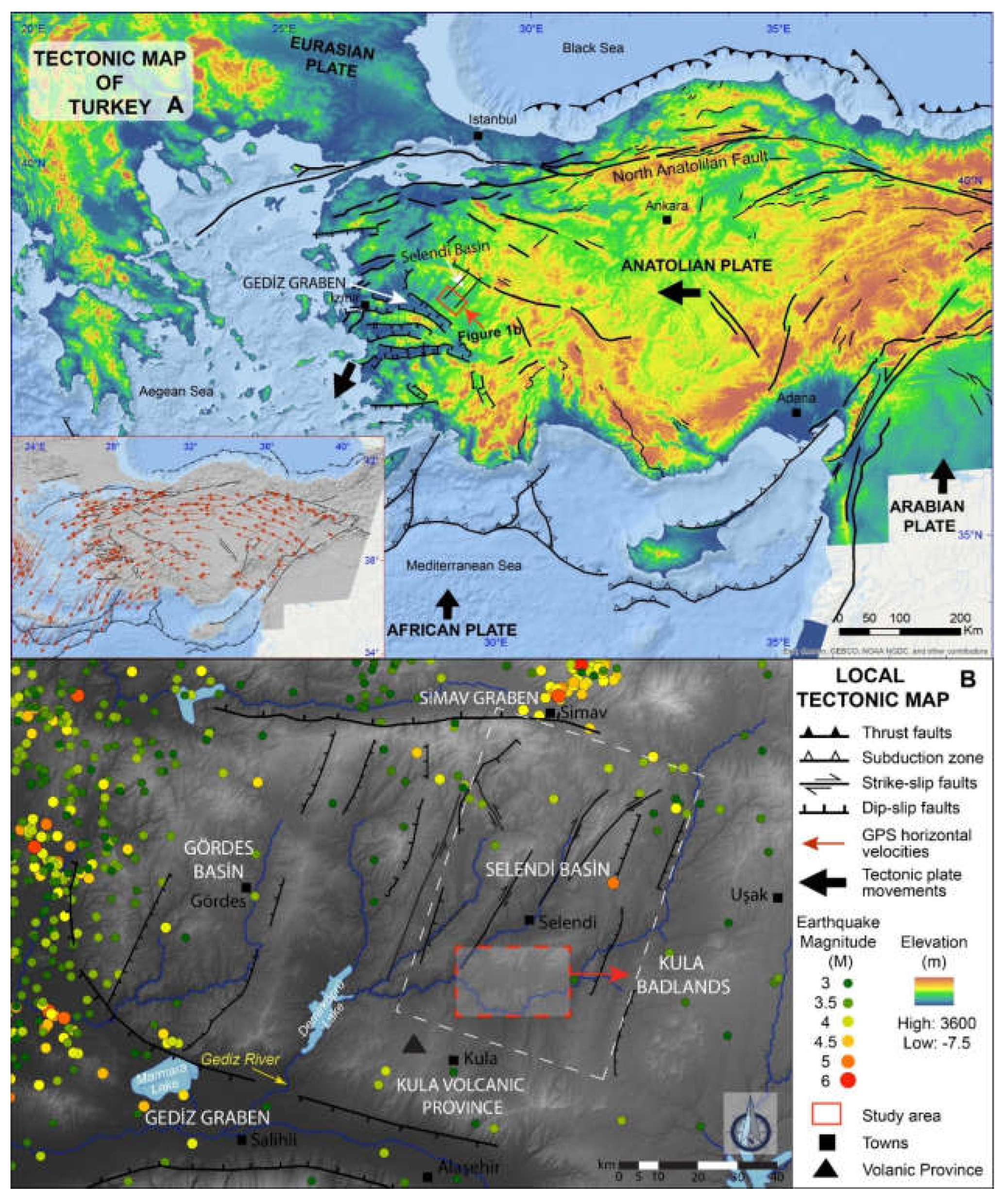
2. Study Area
Tectonic and Geological Setting
3. Materials and Methods
3.1. Geological and Structural Mapping
3.2. Morphometric Analysis
3.2.1. Aspect Maps (Gully and Badland Morphology)
3.2.2. SLk Analysis
4. Results
4.1. Gully Morphology: Badland Characterization
4.2. Rock-Type: Lithological Variety
4.3. The Rock Structure: Geometry of Faulting and Folding
4.4. Quaternary Sedimentation
- Poorly-sorted fluvial sediments with clasts up to 3 cm of carbonate-metamorphic provenance.
- Well-sorted fluvial sediments with clasts up to 20 cm of carbonate-metamorphic provenance.
- Poorly-sorted fluvial sediments with clasts up to 3 cm of carbonate provenance.
- Well-sorted fluvial sediments with clasts up to 20 cm of carbonate provenance (Appendix A).
- Colluvium deposits.
4.5. SLk Indices and Connection to Faults

| Stratigraphic Columns | Explanation |
|---|---|
| 1, 2 | Located on a steep slope. No Quaternary fluvial sedimentation was observed on column 1. Around a meter thick Quaternary fluvial sediments were observed on column 2 downstream. A NE-SW-orientated fault was present near these outcrops. |
| 3, 4, 5 | Demonstrate a similar drainage pattern along observed faults. The carbonate-rich Quaternary fluvial sediments were mapped in these outcrops, getting relatively thicker downstream along a fault scarp. Relatively higher SLk index values were observed in these fault zones. |
| 6, 7 | Higher SLk index values on the steeper part of the slope were observed on columns 6 and 7. Column 6 is located on a step-like surface near an inferred fault, which indicates more stability for sediment preservation. The carbonate-rich Quaternary sedimentary unit is around 1.5 m thick in length. In a similar example, the relatively thicker carbonate-rich Quaternary fluvial sediments (2 m) and colluvial sediments above (almost 2.5 m) were observed on column 7 near a fault. These two outcrops are located near a fault zone. The higher SLk index values also confirm this observation. |
| 8, 9, 10 | The carbonate-rich Quaternary fluvial sediments of coarse to fine grain size were observed on columns 8, 9 and 10 downstream. In particular, column 9 has a relatively thicker fluvial sedimentary unit, and both 9 and 10 have colluvial deposits on top. Columns 9 and 10 are near faults, as shown in Figure 11 and Appendix A. Rather higher SLk index values confirm this observation. |
| 11, 12 | 11 and 12 display a rather different sedimentation pattern downstream on the less steep slope part of the selected gully. It must be noted that these two outcrops are located on the opposite side of the gully at relatively different heights. Colluvial deposits were observed above the Quaternary fluvial sediments on column 11. A relatively thicker Quaternary sedimentary unit was observed, but no colluvial deposits were reported on column 12 near a fault. |
| 13, 14 | Similarly, carbonate-rich Quaternary fluvial sediments were reported on columns 13 and 14 (about 3 and 6 m, respectively). The thicker Quaternary fluvial sediment package on column 14 is located after a NW-SE-orientated fault downstream. The SLk index value indicates a slight change in this fault zone as well. |
| 15, 16, 17, 18 | An additional four stratigraphic columns were selected in gully X (Figure 5). Columns 15, 16, 17 and 18 have various Quaternary–Miocene boundary levels and Quaternary sediment thicknesses. Columns 16 and 17 are located on a fault zone of two NW-SE-striking normal faults. Quaternary fluvial sediments consisting of pebbles of carbonate and metamorphic provenance seem to be inherited from column 15 upstream. These preserved Quaternary fluvial sediments are relatively thicker on columns 16 and 17 (i.e., both 2.3 m) compared to 15 and 18. Note that column 18 is located on a footwall, a zone of no sediment preservation. |
5. Discussion
5.1. Quaternary Sedimentation and Erosion within the Context of Structural Control
5.2. Structural Control in Gully Morphology and Badland Development
5.3. Potential Triggers and Controlling Factors
- Lithological variety, particularly the presence of visibly erodible clay-sized sediments of the Ahmetler Formation contributing to rock-mass weakening, is regarded as a conditioning factor,
- The existing fold structure (i.e., the orientation of bedding, folds) serves as the conditioning factor as it prepares the basin for preferential water flow in the palaeo- and present-day topography,
- Faulting and its geometry work as a controlling factor as different orientated faults generate (i) combined erosion/sedimentation surfaces and (ii) morphological patterns for water flow in the form of deepened gullies.
6. Conclusions
Author Contributions
Funding
Acknowledgments
Conflicts of Interest
Appendix A

References
- Bryan, R.; Yair, A. Badland: Geomorphology and Piping; Geo Books: Norwich, UK, 1982. [Google Scholar]
- Kašanin-Grubin, M.; Vergari, F.; Troiani, F.; Della Seta, M. The Role of Lithology. In Badlands Dynamics in a Context of Global Change; Elsevier: Amsterdam, The Netherlands, 2018; pp. 61–109. ISBN 9780128130544. [Google Scholar]
- Joshi, V.U.; Nagare, V.B. Badland formation along the Pravara River, Western Deccan, India. Can neotectonics be the cause? Z. Geomorphol. 2013, 57, 349–370. [Google Scholar] [CrossRef]
- Van Gorp, W.; Veldkamp, A.; Temme, A.J.A.M.; Maddy, D.; Demir, T.; van der Schriek, T.; Reimann, T.; Wallinga, J.; Wijbrans, J.; Schoorl, J.M. Fluvial response to Holocene volcanic damming and breaching in the Gediz and Geren rivers, western Turkey. Geomorphology 2013, 201, 430–448. [Google Scholar] [CrossRef]
- Ranga, V.; Mohapatra, S.N.; Pani, P. Geomorphological evolution of badlands based on the dynamics of palaeo-channels and their implications. J. Earth Syst. Sci. 2015, 124, 909–920. [Google Scholar] [CrossRef] [Green Version]
- Martínez-Murillo, J.F.; Nadal-Romero, E. Perspectives on Badland Studies in the Context of Global Change. In Badlands Dynamics in a Context of Global Change; Elsevier: Amsterdam, The Netherlands, 2018; pp. 1–25. ISBN 9780128130544. [Google Scholar]
- Torri, D.; Rossi, M.; Brogi, F.; Marignani, M.; Bacaro, G.; Santi, E.; Tordoni, E.; Amici, V.; Maccherini, S. Badlands and the dynamics of human history, land use, and vegetation through centuries. In Badlands Dynamics in a Context of Global Change; Elsevier: Amsterdam, The Netherlands, 2018; pp. 111–153. ISBN 9780128130544. [Google Scholar]
- Boardman, J.; Parsons, A.J.; Holland, R.; Holmes, P.J.; Washington, R. Development of badlands and gullies in the Sneeuberg, Great Karoo, South Africa. CATENA 2003, 50, 165–184. [Google Scholar] [CrossRef]
- Nadal-Romero, E.; Latron, J.; Martí-Bono, C.; Regüés, D. Temporal distribution of suspended sediment transport in a humid Mediterranean badland area: The Araguás catchment, Central Pyrenees. Geomorphology 2008, 97, 601–616. [Google Scholar] [CrossRef]
- Moreno-de Las Heras, M.; Gallart, F. The origin of badlands. In Badlands Dynamics in a Context of Global Change; Elsevier: Amsterdam, The Netherlands, 2018; pp. 27–59. ISBN 9780128130544. [Google Scholar]
- Moretti, S.; Rodolfi, G. A typical “calanchi” landscape on the Eastern Apennine margin (Atri, Central Italy): Geomorphological features and evolution. CATENA 2000, 40, 217–228. [Google Scholar] [CrossRef]
- Nadal-Romero, E.; Vicente-Serrano, S.M.; Jiménez, I. Assessment of badland dynamics using multi-temporal Landsat imagery: An example from the Spanish Pre-Pyrenees. CATENA 2012, 96, 1–11. [Google Scholar] [CrossRef]
- Hevia, J.N.; de Araújo, J.C.; Manso, J.M. Assessment of 80 years of ancient-badlands restoration in saldaña, Spain. Earth Surf. Process. Landf. 2014, 39, 1563–1575. [Google Scholar] [CrossRef]
- Vericat, D.; Smith, M.W.; Brasington, J. Patterns of topographic change in sub-humid badlands determined by high resolution multi-temporal topographic surveys. CATENA 2014, 120, 164–176. [Google Scholar] [CrossRef]
- Bentivenga, M.; Agosta, F.; Palladino, G.; Piccarreta, M.; Prosser, G. Structural control on badland slope evolution: A case study from the southern Apennines (Italy). Geomorphology 2021, 374, 107518. [Google Scholar] [CrossRef]
- Bentivenga, M.; Capolongo, D.; Palladino, G.; Piccarreta, M. Geomorphological map of the area between Craco and Pisticci (Basilicata, Italy). J. Maps 2015, 11, 267–277. [Google Scholar] [CrossRef]
- Agarwal, K.; Singh, I.; Sharma, M.; Sharma, S.; Rajagopalan, G. Extensional tectonic activity in the cratonward parts (peripheral bulge) of the Ganga Plain foreland basin, India. Int. J. Earth Sci. 2002, 91, 897–905. [Google Scholar] [CrossRef]
- Densmore, A.L. Footwall topographic development during continental extension. J. Geophys. Res. 2004, 109, F03001. [Google Scholar] [CrossRef] [Green Version]
- Cowie, P.A.; Attal, M.; Tucker, G.E.; Whittaker, A.C.; Naylor, M.; Ganas, A.; Roberts, G.P. Investigating the surface process response to fault interaction and linkage using a numerical modelling approach. Basin Res. 2006, 18, 231–266. [Google Scholar] [CrossRef]
- Whittaker, A.C.; Attal, M.; Allen, P.A. Characterising the origin, nature and fate of sediment exported from catchments perturbed by active tectonics. Basin Res. 2010, 22, 809–828. [Google Scholar] [CrossRef] [Green Version]
- Vanmaercke, M.; Kettner, A.J.; van Den Eeckhaut, M.; Poesen, J.; Mamaliga, A.; Verstraeten, G.; Rãdoane, M.; Obreja, F.; Upton, P.; Syvitski, J.P.M.; et al. Moderate seismic activity affects contemporary sediment yields. Prog. Phys. Geogr. 2014, 38, 145–172. [Google Scholar] [CrossRef] [Green Version]
- Graveleau, F.; Strak, V.; Dominguez, S.; Malavieille, J.; Chatton, M.; Manighetti, I.; Petit, C. Experimental modelling of tectonics-erosion-sedimentation interactions in compressional, extensional, and strike-slip settings. Geomorphology 2015, 244, 146–168. [Google Scholar] [CrossRef]
- Veldkamp, A.; Van den Berg, M.W.; Van Dijke, J.J.; Van den Berg van Saparoea, R.M. Reconstructing Late Quaternary fluvial process controls in the upper Aller Valley (North Germany) by means of numerical modeling. Neth. J. Geosci. 2002, 81, 375–388. [Google Scholar] [CrossRef] [Green Version]
- Schoorl, J.M.; Temme, A.J.A.M.; Veldkamp, T. Modelling centennial sediment waves in an eroding landscape—Catchment complexity. Earth Surf. Process. Landf. 2014, 39, 1526–1537. [Google Scholar] [CrossRef]
- Lima, C.C.U.; Bezerra, F.H.R.; Nogueira, F.C.C.; Maia, R.P.; Sousa, M.O.L. Quaternary fault control on the coastal sedimentation and morphology of the São Francisco coastal plain, Brazil. Tectonophysics 2014, 633, 98–114. [Google Scholar] [CrossRef]
- Hack, J.T. Stream-profile analysis and stream-gradient index. J. Res. US Geol. Surv. 1973, 1, 421–429. [Google Scholar]
- Seeber, L.; Gornitz, V. River profiles along the Himalayan arc as indicators of active tectonics. Tectonophysics 1983, 92, 335–367. [Google Scholar] [CrossRef]
- Crosby, B.T.; Whipple, K.X. Knickpoint initiation and distribution within fluvial networks: 236 waterfalls in the Waipaoa River, North Island, New Zealand. Geomorphology 2006, 82, 16–38. [Google Scholar] [CrossRef]
- Kirby, E.; Whipple, K.X. Expression of active tectonics in erosional landscapes. J. Struct. Geol. 2012, 44, 54–75. [Google Scholar] [CrossRef]
- Demoulin, A.; Mather, A.; Whittaker, A. Fluvial archives, a valuable record of vertical crustal deformation. Quat. Sci. Rev. 2017, 166, 10–37. [Google Scholar] [CrossRef] [Green Version]
- Babaei, S.; Dehbozorgi, M.; Hosseiniasl, A.; Hakimi Asiabar, S. New insights into the effect of the quaternary fault activity on river knickpoints in the Central Alborz (Iran). Quat. Int. 2020, 562, 104–120. [Google Scholar] [CrossRef]
- Viveen, W.; Baby, P.; Hurtado-Enríquez, C. Assessing the accuracy of combined DEM-based lineament mapping and the normalised SL-index as a tool for active fault mapping. Tectonophysics 2021, 813, 228942. [Google Scholar] [CrossRef]
- UNESCO. Global Geoparks. Available online: http://www.unesco.org/new/en/natural-sciences/environment/earth-sciences/unesco-global-geoparks/list-of-unesco-global-geoparks/turkey/kula-volcanic/ (accessed on 15 August 2020).
- Erinç, S. The young volcanic topography of the Kula-Adala area. Istanb. Univ. Cografya Enst. Dergisi 1970, 17, 7–22. [Google Scholar]
- Maddy, D.; Demir, T.; Bridgland, D.R.; Veldkamp, A.; Stemerdink, C.; van der Schriek, T.; Schreve, D. The Pliocene initiation and Early Pleistocene volcanic disruption of the palaeo-Gediz fluvial system, Western Turkey. Quat. Sci. Rev. 2007, 26, 2864–2882. [Google Scholar] [CrossRef]
- Veldkamp, A.; Baartman, J.E.M.; Coulthard, T.J.; Maddy, D.; Schoorl, J.M.; Storms, J.E.A.; Temme, A.J.A.M.; van Balen, R.; van De Wiel, M.J.; van Gorp, W.; et al. Two decades of numerical modelling to understand long term fluvial archives: Advances and future perspectives. Quat. Sci. Rev. 2017, 166, 177–187. [Google Scholar] [CrossRef] [Green Version]
- Van Gorp, W.; Temme, A.J.A.M.; Veldkamp, A.; Schoorl, J.M. Modelling long-term (300 ka) upland catchment response to multiple lava damming events. Earth Surf. Process. Landf. 2015, 40, 888–900. [Google Scholar] [CrossRef]
- Bunbury, J.M.; Hall, L.; Anderson, G.J.; Stannard, A. The determination of fault movement history from the interaction of local drainage with volcanic episodes. Geol. Mag. 2001, 138, 185–192. [Google Scholar] [CrossRef]
- Ercan, T.; Türkecan, A.; Mengü, A.; Günay, E. Kula-Selendi (Manisa) Dolaylarının Jeolojisi. Jeol. Muhendis. 1983, 17, 3–28. [Google Scholar]
- Westaway, R.; Guillou, H.; Yurtmen, S.; Beck, A.; Bridgland, D.; Demir, T.; Scaillet, S.; Rowbotham, G. Late Cenozoic uplift of western Turkey: Improved dating of the Kula Quaternary volcanic field and numerical modelling of the Gediz River terrace staircase. Glob. Planet. Change 2006, 51, 131–171. [Google Scholar] [CrossRef]
- Heineke, C.; Niedermann, S.; Hetzel, R.; Akal, C. Surface exposure dating of Holocene basalt flows and cinder cones in the Kula volcanic field (Western Turkey) using cosmogenic 3He and 10Be. Quat. Geochronol. 2016, 34, 81–91. [Google Scholar] [CrossRef] [Green Version]
- Yilmaz, Y.; Genç, Ş.C.; Gürer, F.; Bozcu, M.; Yilmaz, K.; Karacik, Z.; Altunkaynak, Ş.; Elmas, A. When did the western Anatolian grabens begin to develop? Geol. Soc. Spec. Publ. 2000, 173, 353. [Google Scholar] [CrossRef]
- Westaway, R.; Pringle, M.; Yurtmen, S.; Demir, T.; Bridgland, D.; Rowbotham, G.; Maddy, D. Pliocene and Quaternary Regional Uplift in Western Turkey: The Gediz River Terrace Staircase and the Volcanism at Kula. Tectonophysics 2004, 391, 121–169. [Google Scholar] [CrossRef]
- Maddy, D.; Veldkamp, A.; Jongmans, A.G.; Candy, I.; Demir, T.; Schoorl, J.M.; van der Schriek, T.; Stemerdink, C.; Scaife, R.G.; van Gorp, W. Volcanic disruption and drainage diversion of the palaeo-Hudut River, a tributary of the Early Pleistocene Gediz River, Western Turkey. Geomorphology 2012, 165, 62–77. [Google Scholar] [CrossRef]
- Maddy, D.; Demir, T.; Bridgland, D.R.; Veldkamp, A.; Stemerdink, C.; van der Schriek, T.; Westaway, R. An obliquity-controlled Early Pleistocene river terrace record from Western Turkey? Quat. Res. 2005, 63, 339–346. [Google Scholar] [CrossRef]
- Maddy, D.; Veldkamp, A.; Demir, T.; Aytaç, A.S.; Schoorl, J.M.; Scaife, R.; Boomer, I.; Stemerdink, C.; van der Schriek, T.; Aksay, S.; et al. Early Pleistocene River Terraces of the Gediz River, Turkey: The role of faulting, fracturing, volcanism and travertines in their genesis. Geomorphology 2020, 358, 107102. [Google Scholar] [CrossRef]
- Van Gorp, W.; Temme, A.J.A.M.; Baartman, J.E.M.; Schoorl, J.M. Landscape evolution modelling of naturally dammed rivers. Earth Surf. Process. Landf. 2014, 39, 1587–1600. [Google Scholar] [CrossRef]
- Maddy, D.; Veldkamp, A.; Demir, T.; van Gorp, W.; Wijbrans, J.R.; van Hinsbergen, D.J.J.; Dekkers, M.J.; Schreve, D.; Schoorl, J.M.; Scaife, R.; et al. The Gediz River fluvial archive: A benchmark for Quaternary research in Western Anatolia. Quat. Sci. Rev. 2017, 166, 289–306. [Google Scholar] [CrossRef] [Green Version]
- Ercan, T. Interpretation of Geochemical, Radiometric and Isotopic Data on Kula Volcanics (Manisa—W. Anatolia). Türk. Jeol. Bül. 1993, 36, 113–129. [Google Scholar]
- Taymaz, T.; Tan, O.; Yolsal, S. Active Tectonics of Turkey and Surroundings and Seismic Risk in the Marmara Sea Region. In Proceedings of the IWAM04, Mizunami, Japan, 31 March 2004. [Google Scholar]
- Şengör, A.M.C.; Tüysüz, O.; İmren, C.; Sakınç, M.; Eyidoğan, H.; Görür, N.; Le Pichon, X.; Rangin, C. The North Anatolian Fault: A new look. Annu. Rev. Earth Planet. Sci. 2005, 33, 37–112. [Google Scholar] [CrossRef]
- Le Pichon, X.; Imren, C.; Rangin, C.; Şengör, A.M.C.; Siyako, M. The South Marmara Fault. Int. J. Earth Sci. 2014, 103, 219–231. [Google Scholar] [CrossRef]
- Özbakir, A.D.; Govers, R.; Wortel, R. Active faults in the Anatolian-Aegean plate boundary region with Nubia. Turk. J. Earth Sci. 2017, 26, 30–56. [Google Scholar] [CrossRef]
- European Environment Agency European Environment Agency (EEA). Available online: https://land.copernicus.eu/imagery-in-situ/eu-dem/eu-dem-v1.1/view (accessed on 3 March 2020).
- USGS Earthquake Catalog. Available online: https://earthquake.usgs.gov/earthquakes/search/ (accessed on 28 July 2020).
- Avcıoğlu, A.; Görüm, T.; Akbaş, A.; Moreno-de las Heras, M.; Yıldırım, C.; Yetemen, Ö. Regional distribution and characteristics of major badland landscapes in Turkey. CATENA 2022, 218, 106562. [Google Scholar] [CrossRef]
- Fick, S.E.; Hijmans, R.J. WorldClim 2: New 1-km spatial resolution climate surfaces for global land areas. Int. J. Climatol. 2017, 37, 4302–4315. [Google Scholar] [CrossRef]
- USGS ComCat Earthquake Hazards Program. The ANSS Comprehensive Earthquake Catalog (ComCat). Available online: http://earthquake.usgs.gov/earthquakes/search/ (accessed on 20 May 2021).
- Bozkurt, E. Origin of NE-trending basins in western Turkey. Geodin. Acta 2003, 16, 61–81. [Google Scholar] [CrossRef]
- Purvis, M.; Robertson, A. A pulsed extension model for the Neogene-Recent E-W-trending Alaşehir Graben and the NE-SW-trending Selendi and Gördes Basins, Western Turkey. Tectonophysics 2004, 391, 171–201. [Google Scholar] [CrossRef]
- Ersoy, Y.E.; Helvaci, C.; Sözbilir, H. Tectono-stratigraphic evolution of the NE-SW-trending superimposed Selendi basin: Implications for late Cenozoic crustal extension in Western Anatolia, Turkey. Tectonophysics 2010, 488, 210–232. [Google Scholar] [CrossRef]
- Çiftçi, N.B.; Bozkurt, E. Structural evolution of the Gediz Graben, SW Turkey: Temporal and spatial variation of the graben basin. Basin Res. 2010, 22, 846–873. [Google Scholar] [CrossRef]
- McKenzie, D. Active Tectonics of the Mediterranean Region. Geophys. J. R. Astron. Soc. 1972, 30, 109–185. [Google Scholar] [CrossRef] [Green Version]
- McClusky, S.; Balassanian, S.; Barka, A.; Demir, C.; Ergintav, S.; Georgiev, I.; Gurkan, O.; Hamburger, M.; Hurst, K.; Kahle, H.; et al. Global Positioning System constraints on plate kinematics and dynamics in the eastern Mediterranean and Caucasus. J. Geophys. Res. Solid Earth 2000, 105, 5695–5719. [Google Scholar] [CrossRef]
- McKenzie, D. The East Anatolian Fault: A major structure in Eastern Turkey. Earth Planet. Sci. Lett. 1976, 29, 189–193. [Google Scholar] [CrossRef]
- Taymaz, T.; Jackson, J.; Westaway, R. Earthquake mechanisms in the Hellenic Trench near Crete. Geophys. J. Int. 1990, 102, 695–731. [Google Scholar] [CrossRef]
- Ketin, I. Über die tektonisch-mechanischen Folgerungen aus den großen anatolischen Erdbeben des letzten Dezenniums. Geol. Rundsch. 1948, 36, 77–83. [Google Scholar] [CrossRef]
- Özeren, M.S.; Holt, W.E. The dynamics of the eastern Mediterranean and eastern Turkey. Geophys. J. Int. 2010, 183, 1165–1184. [Google Scholar] [CrossRef] [Green Version]
- Dewey, J.F.; Şengör, A.M.C. Aegean and surrounding regions: Complex multiplate and continuum tectonics in a convergent zone. Bull. Geol. Soc. Am. 1979, 90, 84–92. [Google Scholar] [CrossRef]
- Le Pichon, X. Land-locked oceanic basins and continental collision: The Eastern Mediterranean as a case example. Mt. Build. Process. 1982, 201–211. [Google Scholar] [CrossRef]
- Seyitoğlu, G. Late Cenozoic tectono-sedimentary development of the Selendi and Uşak-Güre basins: A contribution to the discussion on the development of east–west and north trending basins in western Turkey. Geol. Mag. 1997, 134, 163–175. [Google Scholar] [CrossRef]
- Bozkurt, E. Neotectonics of Turkey—A synthesis. Geodin. Acta 2001, 14, 3–30. [Google Scholar] [CrossRef] [Green Version]
- Bozkurt, E.; Sözbilir, H. Tectonic evolution of the Gediz Graben: Field evidence for an episodic, two-stage extension in western Turkey. Geol. Mag. 2004, 141, 63–79. [Google Scholar] [CrossRef]
- Purvis, M.; Robertson, A. Miocene sedimentary evolution of the NE-SW-trending Selendi and Gördes Basins, W Turkey: Implications for extensional processes. Sediment. Geol. 2005, 174, 31–62. [Google Scholar] [CrossRef]
- Koçyiǧit, A.; Yusufoǧlu, H.; Bozkurt, E. Evidence from the Gediz graben for episodic two-stage extension in western Turkey. J. Geol. Soc. 1999, 156, 605. [Google Scholar] [CrossRef]
- Seyitoglu, G.; Cemen, I.; Tekeli, O. Extensional folding in the Alasehir (Gediz) graben, western Turkey. J. Geol. Soc. 2000, 157, 1097. [Google Scholar] [CrossRef]
- Çiftçi, N.B.; Bozkurt, E. Folding of the Gediz Graben fill, SW Turkey: Extensional and/or contractional origin? Geodin. Acta 2008, 21, 145–167. [Google Scholar] [CrossRef]
- Şengör, A.M.C.; Bozkurt, E. Layer-parallel shortening and related structures in zones undergoing active regional horizontal extension. Int. J. Earth Sci. 2013, 102, 101–119. [Google Scholar] [CrossRef]
- Maddy, D.; Demir, T.; Veldkamp, A.; Bridgland, D.R.; Stemerdink, C.; Van Der Schriek, T.; Schreve, D. The obliquity-controlled early Pleistocene terrace sequence of the Gediz River, western Turkey: A revised correlation and chronology. J. Geol. Soc. 2012, 169, 67–82. [Google Scholar] [CrossRef]
- Veldkamp, A.; Candy, I.; Jongmans, A.G.; Maddy, D.; Demir, T.; Schoorl, J.M.; Schreve, D.; Stemerdink, C.; van der Schriek, T. Reconstructing Early Pleistocene (1.3 Ma) terrestrial environmental change in western Anatolia: Did it drive fluvial terrace formation? Palaeogeogr. Palaeoclimatol. Palaeoecol. 2015, 417, 91–104. [Google Scholar] [CrossRef]
- Ozaner, F.S. Detecting the polycyclic drainage evolution in Kula region (western Turkey) using aerial photographs. ITC J. 1992, 3, 249–253. [Google Scholar]
- Haldon, J.; Roberts, N.; Izdebski, A.; Fleitmann, D.; McCormick, M.; Cassis, M.; Doonan, O.; Eastwood, W.; Elton, H.; Ladstätter, S.; et al. The climate and environment of Byzantine Anatolia: Integrating science, history, and archaeology. J. Interdiscipl. Hist. 2014, 45, 113–161. [Google Scholar] [CrossRef] [Green Version]
- Şen, E.; Aydar, E.; Bayhan, H.; Gourgaud, A. Alkali bazalt ve piroklastik çökellerin volkanolojik özellikleri, kula volkanları, batı anadolu. Yerbilim. Earth Sci. 2014, 35, 219–252. [Google Scholar] [CrossRef] [Green Version]
- Lazzari, M. High-Resolution LiDAR-Derived DEMs in Hydrografic Network Extraction and Short-Time Landscape Changes. Lect. Notes Comput. Sci. 2020, 12250, 723–737. [Google Scholar] [CrossRef]
- Allmendinger, R.W.; Cardozo, N.; Fisher, D.M. Structural Geology Algorithms: Vectors and Tensors; Cambridge University Press: Cambridge, UK, 2011; ISBN 9780511920202. [Google Scholar]
- Cardozo, N.; Allmendinger, R.W. Spherical projections with OSXStereonet. Comput. Geosci. 2013, 51, 193–205. [Google Scholar] [CrossRef]
- Pérez-Peña, J.V.; Azañón, J.M.; Azor, A.; Delgado, J.; González-Lodeiro, F. Spatial analysis of stream power using GIS: SLk anomaly maps. Earth Surf. Process. Landf. 2009, 34, 16–25. [Google Scholar] [CrossRef]
- El Hamdouni, R.; Irigaray, C.; Fernández, T.; Chacón, J.; Keller, E.A. Assessment of relative active tectonics, southwest border of the Sierra Nevada (southern Spain). Geomorphology 2008, 96, 150–173. [Google Scholar] [CrossRef]
- Bull, W.B. Tectonic Geomorphology of Mountains: A New Approach to Paleoseismology; Blackwell: Oxford, UK, 2007; p. 316. [Google Scholar]
- Ghosh, S.; Sivakumar, R. Assessment of morphometric parameters for the development of Relative Active Tectonic Index and its significant for seismic hazard study: An integrated geoinformatic approach. Environ. Earth Sci. 2018, 77, 600. [Google Scholar] [CrossRef]
- Aksay, S.; Schoorl, J.; Veldkamp, A.; Demir, T.; Aytaç, S.; Maddy, D. The influence of structural control in erosion-sedimentation dynamics and morphology of a badland topography. EGU22-11870. In Proceedings of the EGU General Assembly 2022, Vienna, Austria, 23–27 May 2022. [Google Scholar]
- Sözbilir, H. Extensional Tectonics and the Geometry of Related Macroscopic Structures: Field Evidence from the Gediz Detachment, Western Turkey. Turk. J. Earth Sci. 2001, 10, 51–67. [Google Scholar]
- Andrić, N.; Sant, K.; Matenco, L.; Mandic, O.; Tomljenović, B.; Pavelić, D.; Hrvatović, H.; Demir, V.; Ooms, J. The link between tectonics and sedimentation in asymmetric extensional basins: Inferences from the study of the Sarajevo-Zenica Basin. Mar. Pet. Geol. 2017, 83, 305–332. [Google Scholar] [CrossRef]
- García-García, F.; Fernández, J.; Viseras, C.; Soria, J.M. Architecture and sedimentary facies evolution in a delta stack controlled by fault growth (Betic Cordillera, southern Spain, late Tortonian). Sediment. Geol. 2006, 185, 79–92. [Google Scholar] [CrossRef]
- Hovius, N.; Meunier, P.; Lin, C.W.; Chen, H.; Chen, Y.G.; Dadson, S.; Horng, M.J.; Lines, M. Prolonged seismically induced erosion and the mass balance of a large earthquake. Earth Planet. Sci. Lett. 2011, 304, 347–355. [Google Scholar] [CrossRef]


Publisher’s Note: MDPI stays neutral with regard to jurisdictional claims in published maps and institutional affiliations. |
© 2022 by the authors. Licensee MDPI, Basel, Switzerland. This article is an open access article distributed under the terms and conditions of the Creative Commons Attribution (CC BY) license (https://creativecommons.org/licenses/by/4.0/).
Share and Cite
Aksay, S.; Schoorl, J.M.; Veldkamp, A.; Demir, T.; Aytaç, A.S.; Maddy, D. Structurally Controlled Landscape Evolution in Kula Badlands, Western Turkey. Geosciences 2022, 12, 390. https://0-doi-org.brum.beds.ac.uk/10.3390/geosciences12100390
Aksay S, Schoorl JM, Veldkamp A, Demir T, Aytaç AS, Maddy D. Structurally Controlled Landscape Evolution in Kula Badlands, Western Turkey. Geosciences. 2022; 12(10):390. https://0-doi-org.brum.beds.ac.uk/10.3390/geosciences12100390
Chicago/Turabian StyleAksay, Selçuk, Jeroen M. Schoorl, Antonie Veldkamp, Tuncer Demir, Ahmet Serdar Aytaç, and Darrel Maddy. 2022. "Structurally Controlled Landscape Evolution in Kula Badlands, Western Turkey" Geosciences 12, no. 10: 390. https://0-doi-org.brum.beds.ac.uk/10.3390/geosciences12100390