

The Geoscience of In-Situ Combustion and High-Pressure Air Injection


Department of Earth, Ocean and Ecological Sciences, University of Liverpool, Liverpool L69 3GP, UK
*
Author to whom correspondence should be addressed.
Geosciences 2022, 12(9), 340; https://0-doi-org.brum.beds.ac.uk/10.3390/geosciences12090340
Submission received: 29 July 2022
/
Revised: 6 September 2022
/
Accepted: 8 September 2022
/
Published: 13 September 2022
Abstract
:Considering the global drive toward net-zero carbon emissions in the near future, the need to find clean sources of energy has never been more important. It is estimated that globally there are tens of thousands of depleted and abandoned oil fields that may be adapted to produce green energy. These may be re-cycled with the help of air injection, either from the production of hydrogen, as a direct result of oxidation of oil, or the exploitation of the inherent increase in heat flow and pressure via enhanced geothermal systems. In the past, the use of in-situ combustion (ISC) and high-pressure air injection (HPAI) have experienced many failures, largely due to poor project design and inappropriate reservoir selection. Here, we review data from field applications, experimental studies, and numerical modelling to define the roles of sub-surface sedimentology and petrophysics, structural geology, geomechanics, mineralogy, diagenesis, and petroleum geology on the success of ISC and HPAI. We show how current knowledge can help mitigate project failure via improved project design and initial reservoir selection. Improvements to the design and implementation of ISC and HPAI projects promise to allow the utilisation of the many abandoned oil fields, to produce green energy with the added benefit of the cost-effective, and materials and energy efficient, re-use of existing oil field infrastructure. We conclude that the integration of field data, laboratory experiments, and numerical modelling methods previously studied can be used to help develop ISC and minimize risk of failure.
1. Introduction
In-situ combustion (ISC), also referred to as fire-flooding, is a thermal Enhanced Oil Recovery (EOR) technique that has been used since the early 1920s [1] and has been employed with varying degrees of success [2,3,4,5,6,7,8]. During ISC, air, or oxygen-enriched air, is injected into the oil-bearing reservoir, and the mixture is ignited to begin combustion [5,9,10]. The complexity of ISC projects varies greatly depending on the target reservoir. In its most simple form, a volume of oil within a reservoir, near an injector well, is ignited creating a combustion front, which is then propagated through the reservoir via air injection, driving oil towards a production well (Figure 1) [11]. Ignition can be achieved by a variety of mechanisms or processes, including auto-ignition, gas burners, electrical heaters, and chemical reactions [12,13,14,15,16]. The combustion front drives fluids towards the production well, using a combination of gas, steam, and water drive, caused by the increase in reservoir temperature and pressure [5,9]. ISC can either be forward or reverse. During forward combustion, the front propagates in the same direction as air injection; during reverse, the front propagates in the opposing direction to the air injection [5,17,18,19]. Reverse combustion is rarely used and will not be discussed further. ISC can further be classified as dry or wet. Dry combustion relies solely on injection of air, or enriched air, into the reservoir, whereas wet combustion utilises simultaneous water and air injection [20,21,22,23,24]. As ISC proceeds, different zones begin to form across the reservoir: these zones are the burned zone, the combustion front, the cracking zone, the vaporisation zone, the steam plateau, the water bank, the oil bank, and the undisturbed reservoir (Figure 1 and Figure 2) [2].
In-situ combustion, where temperatures typically exceed 450 °C, is generally used for the recovery and upgrading of heavy oils (those with an API gravity < 22°, equivalent to a density of 921.8 kg/m3, and viscosity > 100 centipoise, equivalent to 0.1 Pa·s) [25], although lighter oils have been targeted with the same technique [26]. The ISC method is typically referred to as ‘high pressure air injection’ (HPAI) when lighter oils are targeted; in this case the temperature reaches 150 to 300 °C, so low temperature oxidation reactions drive the process [26,27,28,29,30,31,32,33]. Projects that have been classed as HPAI include Buffalo [34], Medicine Pole Hills [28], North Ward-Estes [35], Pennel, Cedar Hills and Little Beaver [36].
Current reasons for implementing ISC include (i) increasing reservoir productivity (EOR) by forcing oil or gas towards a production well [10,28,36,37,38,39]; (ii) in-situ upgrading (ISU) of heavy oils, that would otherwise be highly impure and viscous, by the cracking of oil in the reservoir into purer, less viscous fractions, negating the need for energy intensive processes further down the production chain [40,41,42,43,44,45,46,47]; and (iii) the production of energy by geothermal means [48,49,50,51]. It has been suggested that ISC can be used to produce green energy, either from the generation of hydrogen in the reservoir directly from the oil [43,52,53] or from the exploitation of the inherently elevated heat flow resulting from ISC via enhanced geothermal systems [48,50,54,55].
Published work on ISC can be categorised in terms of: field applications [29,37,56,57,58,59], experimental studies [19,60,61,62,63], and modelling studies [38,64,65,66]. Design and implementation are essential to the realisation of an ISC project, with well location, air injection requirements, and reservoir choice playing critical roles its success [4,67]. There are several factors which must be understood to achieve the maximum efficiency of an ISC project; these include the geology of the reservoir [68], the chemistry of the oil within the reservoir [7], and the configuration of the injection and production wells [69].
There has been decrease in interest in ISC since the 1970’s, likely a consequence of the large number of early failures during field tests (55% of projects under taken in the USA between 1960 and 1990 failed [68]). The majority of these failures have been retrospectively attributed to inappropriate reservoir selection [59,67]. The most successful ongoing ISC projects have been running since the 1970s and have involved careful consideration of all these factors with integration of field data, lab data, and models [59,70]. The following review aims to systematically address the following questions:
- How and why is ISC currently used?
- What is the role of laboratory experiments in the process workflow?
- Where are current projects taking place and how successful are they?
- How is numerical modelling used in conjunction with experimental work in the project design process?
- What are the roles of sub-surface geology and oil chemistry in project success?
- How can current knowledge be used to develop ISC as a clean energy source?
2. What Is In-Situ Combustion?
The process of ISC has been implemented with varying degrees of success since the 1920s [67,71], most commonly as a thermal enhanced oil recovery (EOR) technique [10,36,37]. Some applications have used ISC as a primary oil recovery method [72]. To initiate ISC, a portion of the oil in the reservoir is ignited, causing it to crack and deposit fuel, commonly referred to as coke [5,10]. In the context of ISC, the term coke, defined as the product of partial oxidation of oil with low H/C ratio, is routinely used to describe the fuel that drives the combustion process [73]. Together with the air injected into the reservoir, this fuel creates a combustion front that is able to self-propagate through the reservoir as a function of reactions occurring in the reservoir, ahead of the combustion front. These sets of reactions (Reactions 1 – 3) are: Low Temperature Oxidation (reservoir temperature to 300 °C; LTO), Medium Temperature Oxidation (~300 to ~350 °C; MTO), and High Temperature Oxidation (~350 to >525 °C; HTO) (Figure 3) [74,75,76,77,78,79].
During LTO reactions (Reaction 1), crude oil oxidises without generating carbon oxides. The products of LTO reactions include alcohols, aldehydes, ketones, carboxylic acids, and hydroperoxides. LTO reactions also increase the asphaltene content of the oil in the reservoir [80], leading to elevated viscosity and density, reducing production rates. During MTO reactions (Reaction 2), fuel (coke) deposition reactions also occur following LTO reactions as temperatures increase. Distillation and pyrolysis produce hydrogen gas and coke, which is left behind as more volatile fractions (hydrocarbon gases), are vapourised [7,8]. HTO reactions (Reaction 3) burn the deposited fuel (coke) in the presence of oxygen and produce carbon oxides; this is known as the combustion front, which is the highest temperature zone [76,81]. LTO, MTO, and HTO reactions can happen simultaneously across the reservoir as a result of the different temperature zones created ahead of the combustion front (Figure 3). In the initial phase of combustion, LTO and HTO reactions occur at different distances from the injection well. In the later phases of combustion, heat conduction ahead of the combustion front is reduced due to low velocity of the combustion front, resulting in LTO and HTO reactions occurring at almost the same location. Careful consideration and design of injection and production well locations can mitigate this effect and maintain high oil recovery over the life of the project. Larger lateral well spacing (see Section 5.3) typically leads to higher oil recovery per well but commensurate with slower combustion front advancement and production rate [82].
![Geosciences 12 00340 g003]()
Figure 3.
Schematic diagram showing the reaction zones across the reservoir between the post and pre-burn zones. The low temperature oxidation (LTO) reactions occur furthest from the combustion front between the reservoir temperature and 300 °C, medium temperature oxidation (MTO), or fuel deposition (FD) occurs between 300 and 350 °C and at the combustion front the fuel is burnt during high temperature oxidation (HTO), resulting in temperatures in excess of 350 °C [3,83].

LTO (reservoir temperatures to 300 °C): oil + oxygen → aldehydes + ketones + carboxylic acids + hydroperoxides + coke + water
MTO (300 to 350 °C): oil + oxygen → coke + hydrogen
HTO (> 350 °C): coke + oxygen → short-chain HCs + CO + CO2
Due to the highly complex suite of chemical reactions occurring during LTO, ISC reactions can be subdivided into temperature ranges, characterised by a dominant reaction (Reactions 4 to 7) to reflect the importance of these reactions in the sustainability of the combustion process [83].
50 to 150 °C: heavy oil + oxygen → aldehydes + coke + water + CO + CO2
150 to 200 °C: aldehydes + oxygen → alcohols + ketones + water
200 to 250 °C: aldehydes + ketones + oxygen → hydroperoxides + carboxylic acids + water
250 to 300 °C: alcohols + aldehydes + oxygen → hydroperoxides + ketones + water
Although LTO reactions are vital for successful ISC projects, creating too many by-products can increase the viscosity of the oil and coincidentally reduce the oil recovery factor; this is especially problematic during HPAI into reservoirs with light oils. Models using reactions 4 to 7 show that, between 300 and 350 °C (Reaction 2) the dominant product is fuel (coke) as the other products, such as aldehydes, ketones, etc., are used up in preceding reactions or vapourised, leaving behind the less volatile fuel (coke) for the HTO reactions (Reaction 3). In light oil reservoirs (API gravity > 36°, equivalent to a density of 845 kg/m3) LTO reactions (Reaction 1) dominate the process and temperatures may not reach those required for fuel (coke) deposition and, consequently, HTO reactions (Reaction 3) will not occur [84]. Low temperature oxidation reactions may result in an increase in viscosity due to an increase in asphaltene content, which are resistant to break down at low temperatures [85]. A secondary problem reported for light oil reservoir ISC projects is whether injected oxygen will react sufficiently with the oil during LTO, to remove it from the injected air, and thus prevent unwanted, and potentially dangerous, oxygen breakthrough at the production well [80,86].
3. Current Reasons for Using In-Situ Combustion (ISC)
There are three common reasons to implement ISC projects: enhanced oil recovery (EOR), in-situ upgrading (ISU) of heavy and ultra-heavy oils, and producing geothermal energy from heat created during ISC. Enhanced oil recovery seeks to increase the productivity of a field by increasing the oil recovery factor above that which could be achieved by primary and secondary (pressure support by gas or water injection) recovery methods [10]. In-situ upgrading is effectively a useful side effect of ISC that cracks heavy oils into more usable fractions in the reservoir (Figure 4), bypassing the need for large refining facilities [42]. It has also been proposed that geothermal energy can be created from the hot fluids expelled as a result of the ISC process [48]. It also may be possible to utilise the pressure created at the well head by the thermally enhanced recovery of oil for other purposes.
3.1. Enhanced Oil Recovery
Due to the current demands for oil and gas, and the decrease in viable discoveries, EOR is seen as a vital means to maximise the hydrocarbon production of available reserves [10,28,36,37]. Many techniques have been employed in EOR including, steam injection, cyclic steam stimulation, CO2 injection, gas injection, and chemical flooding, as well as ISC [5,6,8,67,87,88]. ISC offers several advantages over other methods, including lower water and natural gas requirements, a smaller surface footprint, higher pressures, and greater oil displacement [33,38], as well as the ability to simultaneously achieve upgrading [42,89].
In some reservoirs, for example Alberta tar sands [90], hydrocarbons cannot flow towards production wells, because the viscosity is too high; some tar sands have hydrocarbons in excess of 1 million centipoise [45]. Thermal EOR techniques have been employed to heat such reservoirs, reducing hydrocarbon viscosity, and thus allowing it to flow [5]. Elevated temperatures also crack the tarry hydrocarbons into lighter fractions, increasing the mobility of the fluid oil as well as depositing fuel (coke) for the advancing combustion front [10]. The increase in mobility ultimately leads to increased recovery factors for the reservoir.
Combustion tube experiments, using scaled physical models with variable parameters, suggested recovery factors of up to 75% for ISC, although this figure varies as a function of the thickness of the sand pack, with some tests showing recovery factors as low as 21% [39]. The large range of recovery factors highlights the importance of knowing the geometry of the reservoir prior to project design. Data from the Buffalo Field, South Dakota, which is the oldest operating high-pressure air injection project currently operating show that, although only 10.2% of the oil originally in place had been recovered at the time of publication (2008), only 14% of the reservoir volume had been swept by ISC. Production performance statistics [29,37] show a second peak in oil production after air injection initially began in the 1980s, which demonstrates that if a larger fraction of the reservoir was injected with air, then more oil would be recovered.
In light oil reservoirs (HPAI), an important aspect of the project is to ensure all oxygen is removed from the injected air, by oxidation reactions between the air and oil, to prevent the dangerous co-production of volatile oil and oxygen. In heavy oil reservoirs, oxygen-consuming reactions are highly effective [86]. In light oil reservoirs, combustion reactions (as opposed to oil-decomposition reactions) may not be sustainable; in this case LTO cracking reactions are likely to be more important than combustion and a flue gas sweep is mostly responsible for oil displacement, where gases formed as a result of cracking and combustion cause the movement of oil [26,28,37,86,91].
3.2. In-Situ Upgrading
Heavy oil, tar sand, oil sand, and bitumen typically have high viscosities (>100 centipoise, 0.1 Pa·s). Such hydrocarbons can also contain high levels of impurities such as asphaltenes, resins, and sulphur [8]. Such oils, if extracted in their natural state, need to be transported to cracking and pyrolysis facilities to upgrade them to more usable fractions that have lower viscosity and fewer impurities (Figure 4). Conventional industrial upgrading methods for heavy oils are energy-intensive processes that generate large volumes of acid gas (i.e., rich in H2S and CO2), consume large volumes of water and hydrogen, and lead to carbon emissions [44]. Conventional upgrading practises increase the environmental footprint of an already environmentally costly process (Figure 4). The in-situ (i.e., sub-surface) upgrading of heavy oils during ISC mitigates this increased environmental impact and reduces industrial costs associated with the conventional upgrading process [40,42,46,47]. ISC is useful for upgrading heavy oils as products of the reactions that drive ISC, including water and hydrogen are generated in-situ, and are key to the upgrading process [44,80,92].
To assess the feasibility of catalyst-aided ISC on upgrading oil in a reservoir, combustion tube experiments were undertaken using Llancanelo oil from the Llancanelo field, Argentina [42]. These experiments revealed that an increase in API gravity at 25 °C from 15 to 24 °C (density decrease from 966 to 910 kg/m3), as well as decreases in viscosity and sulphur, nitrogen, and asphaltene concentrations, may occur during ISU.
Figure 4.
Process of conventional upgrading of heavy oils versus in-situ upgrading, ISU allows for less pollution released in to the atmosphere, and no extra source of hydrogen is required for hydrodesulphurisation, with sulphur and other polluting gases left behind.
Figure 4.
Process of conventional upgrading of heavy oils versus in-situ upgrading, ISU allows for less pollution released in to the atmosphere, and no extra source of hydrogen is required for hydrodesulphurisation, with sulphur and other polluting gases left behind.

3.3. Geothermal Energy Production
It was suggested in 2009 that abandoned, or near end-of-life, oil and gas fields could be utilised to generate geothermal energy [55]. It has been estimated globally that there are tens of thousands of abandoned oil fields that are no longer considered economically viable, yet still contain considerable oil reserves, which could be exploited for geothermal energy [48]. The concept is to use existing oil field wells to inject and retrieve a secondary fluid from the subsurface, taking advantage of the increased temperature as a result of the natural geothermal gradient (Figure 5). Up to 50% of the cost of a geothermal energy project is drilling the well, and so repurposing oilfield infrastructure may be cost-effective for geothermal energy generation [93]. It has been claimed that, depending on reservoir temperature, approximately 2 to 3 MW of electricity may be produced from a typical abandoned well in the South Texas region [55]. To enhance the temperature of the geothermal system, it has been proposed that ISC could be used to increase the temperature of abandoned oil and gas reservoirs to over 600 °C, to enhance the energy recovery using geothermal energy technology [94]. It was suggested that this process produces CO2 [51], but modelling effects of well distance, perforation position, and reservoir permeability on CO2 production suggested that some scenarios can achieve zero CO2 production. It has been proposed that ISC could be used to increase reservoir temperature and, therefore, power output, with an average power output of 8 MW predicted [48,50]. However, this estimate was based on eight years of air injection [48]. Although, the added benefit of significant additional oil recovery from ISC projects may allow geothermal energy costs to be offset, possibly at the expense of the project becoming non-carbon neutral [48].
4. Sources of Information on ISC
Field studies, experiments, and computer (numerical) modelling simulations have all been used, separately and jointly, to assess the processes involved in, and feasibility of, ISC projects. Combustion tube models require upscaling to field scales, and computer models must be fed with accurate field-based and experimentally-derived information to achieve optimum results. The most successful ISC projects integrate data from field studies, experiments, and models [59,95,96].
4.1. Field Application and Case Studies
While the concept of ISC was first patented in the USA in the 1920s [1], it was not implemented on a commercial scale until the 1930s, in the former Soviet Union, and the 1950s in the USA [4]. In the USA, 226 ISC projects were undertaken between 1960 and 1990, with 55% of those projects being deemed a failure, and just 21% judged to be economical successes [68]. Between 1970 and 1995, 19 commercial ISC projects were undertaken, followed by a decline to just four active projects in 2007 [4]. As of 2018, the World Energy Outlook report showed that, of 78 active thermal EOR projects, just 8 are ISC projects (Table 1), and all of them are in the USA [97]. The decrease in interest in ISC is likely to be a consequence of the large number of early failures during field tests although most of the failures have been retrospectively attributed to inappropriate reservoir selection [59,67].
4.1.1. Midway-Sunset Field
A successful pilot ISC project, reported in 1972, was carried out in the Midway-Sunset field, California, USA, following a relatively unsuccessful steam EOR program [56]. It was shown that less than 15% of the oil originally in place (OOIP) had been recovered following steam injection. Coupled with poor results from laboratory steam tests, a different approach was required. In 1972, the steam injectors were switched to air injectors and ISC testing began. After three and a half years in operation, the pilot tests indicated that 80% of the OOIP had been recovered in the pilot area. Following the success of these pilots, in 1980 it was proposed that the project should be expanded, with the addition of seven new injector producer patterns, increasing recovery from 27 to 65%. In 1996, the ISC project was discontinued [98].
4.1.2. Bellevue Oil Field
The longest running and most successful ISC project is the Bellevue Oil Field, Louisiana, USA [4,59]. The field was discovered in the 1920s and has undergone several different EOR cycles. Air injection began in 1970 [4] and still continues to this day [59]. Since the field’s discovery, primary production methods accounted for less than 15% OOIP recovered. It was demonstrated that ISC led to recovery of 60% of the OOIP having now been recovered [59]. It has also been shown that ISC utilised 98% of available oxygen, and left no residual hydrocarbons in swept intervals [70]. The success of the Bellevue Oil Field ISC project has been attributed to the use of combustion tube experiments to calculate the correct air-fuel ratios, which was instrumental in knowing the correct amount of air needed to allow sustained combustion and production.
4.1.3. Medicine Pole Hills Field
The Medicine Pole Hills Field, North Dakota, USA, has been running since 1987 [27], and was listed as an on-going project in 2018 [97]. It differs from many ISC and HPAI projects due to the light oil (39° API, 829 kg/m3), carbonate reservoir geology, low permeability, and high initial reservoir temperature (110 °C) [27,84,99]. Medicine Pole Hills highlights the versatility of HPAI and ISC in increasing the economic output of a range of different reservoirs. C tube experiments were utilised to study the combustion characteristics of the oil. These data were used to design the compressor facility and estimate the burned volume, which were highlighted as key aspects accounting for the success of this ISC project [27].
4.1.4. Other Fields
Despite showing strong potential as a candidate field for ISC, the Hospah Field, New Mexico, USA, was not deemed a success. After initial tests, it was found that only 45% of the oil production target was reached, while 35% more air volume than initially calculated, was injected. Negative performance results led to the project being judged to be uneconomical and it was consequently shut down. The lack of oil recovery from this reservoir was attributed to injected air preferentially migrating through the transition and upper water zones, rather than the overlying oil zone, due to low permeability and high viscosity crude in the oil zone. As a result, the oil was not sufficiently burned to sustain a stable combustion front [100]. Highlighting the importance of fully understanding the characteristics of the reservoir before initiating an ISC project.
The Fry ISC tests in Illinois, USA, which began in 1961, showed how an in-depth analysis of the geology of the reservoir can lead to a successful project [101,102]. Before combustion was attempted, extensive analysis on closely spaced continuous cores from the area was undertaken with the goal of determining the distribution of rock types, the porosity and permeability relationship, the origin of the reservoir, and what affect the reservoir rocks might have on the ISC process [103]. Understanding how geology affected fluid flow and production behaviour during this test was considered essential to the operation of what was concluded to be an economic success [102,104].
Although there is much interest in ISC in Canada [105,106] and China [107,108,109], all active ISC projects seem to be in the USA (Table 1). According to the World Energy Outlook [97], there are eight ongoing ISC thermal EOR projects. As well as Bellevue and Medicine Pole Hills, there are also projects at West Cedar Hills and Cedar Hills North, North Dakota [28,36], Buffalo Field, South Dakota [29,34,36,99]; and Pennel Phase 1, Pennel Phase 2 and Little Beaver, Montana [36].

Table 1.
Table of reservoir and oil properties from reported in-situ combustion (ISC) and high-pressure air injection (HPAI) projects in the literature. Reported properties are rock type, maximum depth, maximum thickness, porosity, permeability, reservoir temperature, oil gravity, oil viscosity, and oil recovery as a percent of oil originally in place. All active projects are shaded grey as listed by the IEA International Energy Agency [97].
| Field | Country | Rock | Depth (m) | Thickness (m) | Porosity (%) | Permeability (mD) | Temperature (°C) | Oil Gravity (°API) | Viscosity (cp) | Recovery (%) | Reference |
|---|---|---|---|---|---|---|---|---|---|---|---|
| Athabasca | Canada | Sand | - | 100 | 35 | 3000–4000 | 18 | 5 | 1,000,000 | 43 | [90] |
| Azraq Basin | Jordan | Mixed | 1112 | - | 18 | 1000 | 40 | 17 | 1000 | 69 | [110] |
| Balaria | Romania | Sand | 85 | 15 | 30 | 500 | 48 | 19 | 120 | 40 | [111] |
| Balol | India | Sand | 1049 | 6.5 | 28 | 8000–15,000 | 70 | 15 | 300 | 45 | [112,113] |
| Bellevue | USA | Sand | 104 | 21 | 32 | 700 | 24 | 19 | 676 | 60 | [59] |
| Buffalo | USA | Carbonate | 2591 | 5 | 15–20 | 10 | 102 | 32 | 2 | 18 | [29] |
| Buffalo | USA | Carbonate | 2576 | 3 | 15–28 | 18–25 | 102 | 27 | 2 | 15 | [36] |
| Cado Pine Island | USA | Sand | 305 | - | 37 | 603 | 32 | 21 | 112 | - | [114] |
| Capa Maddison | USA | Carbonate | 2560 | 6 | 11 | 1 | 108 | 41 | 0.28 | - | [36] |
| Cedar Hills | USA | Carbonate | 3048 | 8 | 5–25 | 1–30 | 110 | 38 | 0.48 | 15 | [36] |
| Charco Redondo | USA | Sand | 61 | - | 30–35 | 2500 | 23 | 18 | 90 | - | [115] |
| Countess | Canada | Sand | 1080 | 8 | 23 | 800–2000 | 28 | 5.8 | 9 | [116] | |
| Driza | Albania | Sand | 450 | 95 | 25 | - | - | 11 | 9000 | - | [117] |
| Esperson Dome | USA | Sand | 814 | 24 | 31 | 200–6300 | 52 | 21 | 90 | 60 | [118] |
| Eyehill | Canada | Sand | 747 | 30 | 34 | 6000 | 29 | 14 | 2750 | 5 | [96] |
| Forest Hill | USA | Sand | 1463 | 4.6 | 27 | 626 | 85 | 10 | 1002 | - | [119] |
| Fosterton | Canada | Sand | 945 | 8.4 | 28 | 958 | 135 | 24 | 15.6 | 33 | [120] |
| Glass Bluff | USA | Carbonate | 2896 | 4 | 10–20 | 18 | 106 | 43 | 0.33 | - | [36] |
| Glen Hummel | USA | Sand | 741 | 3 | 36 | 1000 | 45 | 22 | 74 | 56 | [121] |
| Gloriana | USA | Sand | 488 | 1 | 35 | 1000 | 44 | 21 | 112 | 58 | [121] |
| Government Wells | USA | Sand | 707 | 18 | 32 | 800 | 49 | 22 | 10 | - | [122] |
| Holt Sand Unit | USA | Sand | - | 12 | 20 | 131 | 29 | 32 | 14 | - | [123] |
| Horse Creek | USA | Carbonate | 2781 | 14 | 8–20 | 1–97 | 104 | 32 | 1 | - | [36] |
| Kinsella-B | Canada | Sand | - | 5 | 30 | 200 | 27 | 20 | 90 | 1 | [124] |
| Liaohe Field | China | Sand | 1300 | 6.7 | 25 | 781 | - | 18 | 2000 | - | [125] |
| Little Beaver | USA | Dolomite | 1615 | 12 | 9–20 | 1–10 | 89 | 33 | 3 | 12 | [36] |
| Lower Hospah | USA | Sand | 495 | 9 | 27 | 1100 | 27 | 26 | 55 | 33 | [100] |
| Medicine Pole Hills | USA | Carbonate | 2896 | 4 | 18 | 1–30 | 116 | 39 | 0.48 | 93 | [27] |
| Midway Sunset | USA | Sand | 457 | - | 32 | 1500–4000 | 54 | 12 | 1630 | 73 | [56] |
| Morgan | Canada | Sand | 579 | 9 | 31 | 2000 | 21 | 11 | 1800 | 10 | [126] |
| Pennel | USA | Dolomite | 1661 | 18 | 9–20 | 1–10 | 93 | 31 | 1 | - | [36] |
| Pontotoc | USA | Sand | - | 5 | 27 | 7680 | 19 | 18 | 5000 | 51 | [95] |
| Santhal | India | Sand | 1000 | 15 | 28 | 3000–5000 | 70 | 18 | 200 | - | [4] |
| Silverdale South | Canada | Sand | 564 | 5.5 | 24 | 487 | 28 | 14 | 4420 | 25.5 | [127] |
| South Belridge | USA | Sand | - | 12 | 36 | 8000 | 31 | 13 | 2700 | 71 | [128] |
| Suplacu de Barcau | Romania | Sand | 200 | 10 | 32 | 1700 | 18 | 26 | 2000 | 85 | [129] |
| Trix-Liz | USA | Sand | 1113 | 3 | 28 | 500 | 59 | 24 | 138 | 60 | [121] |
| Utah Tar Sand | USA | Sand | 107 | 4 | 31 | 85 | 11 | 14 | 100,000 | - | [130] |
| Videle Field | Romania | Sand | 850 | 10 | 30 | 300–1500 | 55 | 19 | 66 | 40 | [111] |
| Wabasca | Canada | Sand | 427 | 7 | 30 | 3000 | 15 | 14 | 10,000 | 20 | [131] |
| West Heidellberg | USA | Sand | 3475 | 19 | 14 | 85 | 105 | 18 | 6 | 22 | [132] |
| Wolf Lake | Canada | Sand | 450 | 34 | 31 | - | 15 | 12 | 100,000 | - | [133] |
4.2. Laboratory Experiments
There are two ways to test ISC, through laboratory testing and through field application. The most efficient way to test ISC is via laboratory-based experiments, due to the high costs associated with field tests. The successful Bellevue and Medicine Pole Hills ISC projects were developed on the basis of data collected from combustion tube experiments [27,59]. Following experiments, numerical models were created using the new experimental data, ultimately leading to successful field application [59]. Combustion tubes typically fail to replicate near-adiabatic (i.e., where heat neither enters nor leaves the system) conditions in reservoirs; they are also on a far smaller scale than a reservoir such that careful consideration needs to be given to the upscaling of data generated [134,135,136,137]. Laboratory combustion tube experiments can be operated far more rapidly and cheaply than a field test but care must be taken with interpretation [18,61]. The design and operation of combustion tubes has not been standardised, widely varying different dimensions and operating conditions have thus unfortunately been employed, resulting in data that cannot easily be compared [61].
4.2.1. Combustion Tube Experiments
Combustion tube experiments typically consist of a thin-walled stainless steel tube that is packed with reservoir material, which may be loose sand of various compositions, crushed rock, or whole rock cores. The prepared sample is then saturated with crude oil and the steel tube is then surrounded by a pressure jacket (Figure 6) [18,61,138]. The oil-saturated reservoir material is ignited to simulate the behaviour of oil in a reservoir during ISC. Loss of heat must be countered, either by insulating the tube or by using electrical heaters around the tube, to simulate the near-adiabatic conditions of a large reservoir. While neither insulation or heaters can truly simulate the real reservoir conditions, it has been suggested that the use of heaters may unintentionally influence the movement of the combustion front and alter the results of the experiment [138].
Combustion experiments were used to assess the factors that influence fuel (coke) availability and air requirements during ISC; these are critical aspects that have led to successful and economical ISC field projects [27,59,60]. These combustion experiments compared porous media samples from drill-cores, outcrops, and unconsolidated sand, with 12 different crude oils (with API gravity between 10° and 36°, density of 1000 to 845 kg/m3) [60], leading to the conclusion that the key controls on fuel (coke) availability are the bulk ratio of hydrogen to carbon (the H/C ratio), API gravity (oil density, also related to oil maturity [139,140]), and oil saturation. Fuel availability decreased with increasing H/C ratio and API gravity and increased with increasing oil saturation. These combustion experiments also showed that LTO reactions had the greatest effect on fuel (coke) availability, which is important as the combustion front needs this fuel to propagate through a reservoir [60]. Knowing the correct mix of air and available fuel is key to a viable ISC project [141,142,143].
Combustion tube experiments are versatile and have been used to assess an array of different aspects of ISC projects. They have been used to assess the effect of fracture orientation, and their influence on the success of ISC (see Section 5.1.3) [63]. Combustion tube experiments were used to assess the differences between normal air versus enriched air, and how it affects the air requirements and efficiency of ISC [144,145], revealing that while oxygen enriched air increases the temperature and velocity of the combustion front, it also leads to a risk of early oxygen breakthrough. Other studies have focused on the ability of clay minerals in the reservoir to catalyse combustion reactions during ISC (see Section 5.1.2) [146,147]. Perhaps the most useful application of combustion tube experiments has been to assess the suitability of the type of oil found within the reservoir, which has a direct impact on fuel (coke) deposition, air requirements, temperature, pressure, and products, and, ultimately control the success of sustained combustion front propagation [77,99,143,148].
Figure 6.
A simplified general setup diagram of combustion tube apparatus, with either rock or sand pack saturated with oil held in an insulated jacket, sometimes equipped with extra heating coils to replicate the near-adiabatic conditions found within a reservoir; varying amounts of oxygen and nitrogen are injected to propagate the combustion front through the tube and gases are analysed at the end to give compositional data of the oil.

4.2.2. Other Analytical Approaches Adopted during Experiments
Other experimental analyses that have been employed are thermogravimetric analysis (TGA) and differential scanning calorimetry (DSC) to examine the thermal behaviour of different oils and to provide data on several parameters, such as minimum front temperature, the heat value of crude oil, the amount of coke deposited, and the average H/C ratio during combustion [92,149,150]. Accelerating rate calorimetry (ARC) has also been used to investigate the mechanisms of both LTO and HTO reactions and assess the suitability of a reservoir for air injection-based EOR (Table 2 and Figure 7) [151].
Table 2.
Table of the reported experimental data of combustion properties of different oils from the literature with oil gravity, temperature reached and experimental method used. Thermogravimetry (TG), Differential Scanning Calorimetry (DSC), Accelerated Rate Calorimetry (ARC), and Combustion Tube (CT).
| Oil | API | Temperature | Technique | Reference |
|---|---|---|---|---|
| Adryaman | 26.6 | 548 | CT | [152] |
| Athabasca Bitumen | 8.5 | 550 | TG/DSC | [153] |
| Athabasca Bitumen | 8 | 480 | ARC | [154] |
| Australian light | 38.8 | 255 | CT | [26] |
| Bati Kozluca | 12.4 | 542 | CT | [152] |
| Bati Raman Crude | 11.6 | 615 | RTO | [155] |
| Bati Raman Crude | 14.95 | 560 | TG/DTG | [156] |
| Camurlu | 10.3 | 569 | CT | [152] |
| Clair | 19.8 | 485 | ARC | [154] |
| Clair | 19.8 | 600 | CT | [26] |
| Countess-B | 28 | 606 | CT | [148] |
| Crude oil | 20.8 | 529 | CT | [157] |
| Crude oil 1 | 26.7 | 585 | TG/DTG | [158] |
| Crude oil 2 | 18.7 | 575 | TG/DTG | [158] |
| Crude oil 3 | 12.9 | 565 | TG/DTG | [158] |
| Fosterton oil | 20.5 | 550 | TGA | [150] |
| Garzan | 26.12 | 557 | TG/DTG | [156] |
| Heavy | 20 | 658 | DSC | [159] |
| Heavy 1 | 13 | 386 | CT | [160] |
| Iola | 19.8 | 477 | TG/DSC | [149] |
| Liahoe | 18 | 508 | CT | [161] |
| Light 1 | 32 | 374 | CT | [160] |
| Light oil D | 42.7 | 450 | TG/DSC | [153] |
| Medium 1 | 21 | 374 | CT | [160] |
| Medium 2 | 23 | 442 | CT | [160] |
| Medium oil E | 27.9 | 530 | TG/DSC | [153] |
| Middle east | 29 | 280 | ARC | [162] |
| Neilburg oil | 15.8 | 519 | TG/DTG | [163] |
| North American oil A | 25 | 245 | ARC | [162] |
| North American oil B | 35 | 380 | ARC | [162] |
| North American oil C | 27 | 300 | ARC | [162] |
| Raman | 18.7 | 550 | CT | [152] |
| Tahe Heavy | 22 | 556 | TG/DSC | [164] |
| Wolf lake | 10.3 | 480 | ARC | [154] |
Figure 7.
Cross plot of oil gravity versus temperature for experimental data from the literature (Table 2), with light, medium heavy and extra heavy oil divisions, and low temperature oxidation (LTO), medium temperature oxidation (MTO), and high temperature oxidation (HTO) zones marked. Data are coloured by experimental method, Thermogravimetry (TG), Differential Scanning Calorimetry (DSC), Accelerated Rate Calorimetry (ARC), and Combustion Tube (CT). Combustion tube data show a correlation between oil gravity and temperature, with higher temperatures seen in lower API oils, Thermogravimetry shows a weak correlation but has less temperature difference across the range. CT experiments take reservoir material in to account, so give a more accurate representation of field application.

4.3. Modelling
A reservoir simulation model consists of a geological model, representing the bulk solid volume of the reservoir itself, and a fluid model, which represents the fluid volume (oil, gas, and water) held within the reservoir (Figure 8 and Figure 9) [165]. Production and injection wells are added to the models to allow for dynamic simulation of the processes, which is particularly important for ISC simulation. Well perforations are represented in modelling to allow flow of air in the desired layers of the model [166]. In the case of ISC, a thermal cracking reaction model is also required to describe the liquid and gas phase compositional changes [167]. Computer-based modelling and simulation has recently become popular due to developments in software and hardware; the use of modelling is aimed at trying to increase recovery factors for EOR projects [165]. ISC models tend to require high resolution (and thus slow) simulations in order to capture the attributes of the thin combustion zone [168].
Figure 8.
Grain scale diagram to show how the modelling software quantifies bulk volume (VB), rock volume (VR), fluid volume (VF), residual coat (VS), gas (VG), water (VW) and void volume (VV) for use in the equations.
Figure 8.
Grain scale diagram to show how the modelling software quantifies bulk volume (VB), rock volume (VR), fluid volume (VF), residual coat (VS), gas (VG), water (VW) and void volume (VV) for use in the equations.

A simulation model is typically built from several smaller models, increasing in scale. Rock models represent small-scale elements, such as grain type, porosity, permeability, and oil saturation. These are assembled into facies models, which represent larger scale elements, such as laminations, beds, and stratigraphic members. Facies models are assembled into geological models or geo-models, which represent larger, regional-scale elements, such as formations, groups, and supergroups. These geological volumes are then defined by a cell array with each cell defined by mechanical, chemical, and hydrological properties, that control the behaviour of the model [165,169]. The complexity of a model is controlled by the size and number of cells that make up the model, which is dependent on the size of the reservoir being modelled [165].
Computer modelling has routinely been used to assess different types of EOR mechanisms and to estimate the change (increase) in recovery factor. Typically, ISC is initially modelled due to the complexity and high costs associated with a field test [135,170]. The accuracy of such models is dependent on the quality of data put into them (Figure 10). Petrophysical, geological, geochemical, rock thermal, and pressure-temperature (P-T) properties all have an influence on the output of the model. These three types of properties can be input from a relevant analogue reservoir, or from laboratory experimental data to assess the viability of ISC, or a range of different petrophysical, geological, and geochemical properties can be tested to assess their impact on the success of an ISC project [169]. Thermodynamic and kinetic behaviour of crude oils are key aspects that controls the success of a project, thermodynamic and kinetic data can be derived from combustion tube experiments, but must be upscaled to reservoir-scale models (Figure 10) [38,171,172].
Figure 9.
Chart to show the constituent parts of the model, separated into the static and dynamic elements of the model and what data are used to populate the different parts of the model and where those data come from.
Figure 9.
Chart to show the constituent parts of the model, separated into the static and dynamic elements of the model and what data are used to populate the different parts of the model and where those data come from.

During ISC, the combustion front is only a few centimetres thick, yet it is the most important zone during the overall ISC process [173]. When viewed on a reservoir scale, this thin, dynamic combustion zone only accounts for a tiny fraction of the model potentially representing a problem in a large-scale model. Experimentally-based models of ISC, were developed using adaptive mesh refinement (AMR) to address this problem [174]. The AMR approach increases the precision of selected parts of a model by amalgamating grid blocks away from areas of interest, i.e., the burned reservoir zones, and increasing grid resolution at the areas of interest, i.e., the combustion front. Such a modelling approach has been shown to reduce the number of cells and computational time of standard 1D models by a factor between 3 and 5, with results closely matching those of experimental studies [174].
Models have a wide array of applications for assessing controls on the success of an ISC project. Models have been used to assess the effect of reservoir thickness and heterogeneity (see Section 5.1.3) [66,175], kinetic behaviour of crude oils (see Section 5.2) [176,177,178] and well configurations (see Section 5.3) [170,179].
Figure 10.
Complete workflow from lab experiments to field wide operation of in-situ combustion, this workflow allows for the best results in ISC operation.
Figure 10.
Complete workflow from lab experiments to field wide operation of in-situ combustion, this workflow allows for the best results in ISC operation.

Reaction Models
There are many different reaction models that have been employed to simulate the combustion process, with varying numbers of components and reactions (Table 3). As crude oils are complex mixtures of a large number of different compounds, they are hard to characterise and complex and time-consuming to model [180]. A major part of the total computing time required is related to solving primary equations; therefore, it is important to minimise these while still capturing the key molecular variables [181]. Relatively simple ISC reaction models with fewer components and reactions can produce good results compared to more complex models [182]. Pseudo-components lump together the properties of similar components to reduce the number of components. Pseudo-components help simplify the number of reactants and products involved in ISC reaction modelling [180,183]. Pseudo-components are generated from boiling point and flash point data from an oil; the most important properties of pseudo-components are molecular weight, vapour heat capacity, liquid heat capacity, liquid density, critical pressure, and critical temperature [183].
One of the earliest published reaction models to focus primarily on ISC is the Crookston model [184]; commonly used in commercial simulators as it is a versatile and accurate while also being relatively simple [173]. The model uses heavy oil, light oil, carbon dioxide, coke, water, and inert gas (Table 3) as its reactants. The model only accounts for coke deposition by the cracking of heavy oil and does not consider the role of LTO seen in other reaction schemes [176,185], and therefore may underestimate the amount of fuel and therefore the rate and temperature output of HTO reactions.
There is a simplified reaction model based on a small number of groups of molecules with different degrees of complexity (different numbers of carbon atom), thus reducing the computing time required [181] (Table 3). This method employed oil, instead of coke, as the fuel for combustion, and therefore heat generation. It is less computationally demanding than the Crookston model [184], as it requires fewer primary equations to be solved [181]. Both these models were developed for light oil ISC simulation, and do not adequately predict the behaviour of oils outside of their intended temperature range [178]. It has been suggested that the majority of ISC reaction models, such as with the Crookston and Coats models, attribute fuel (coke) deposition to the process of thermal cracking and neglect the role of LTO reactions [178].
There are reaction models that were developed specifically for ultra-heavy bitumen ISC simulation, which emphasised the importance of LTO reactions in the deposition of fuel (coke); three thermal cracking reactions and two LTO reactions were proposed [176] (Table 3). There was further expansion on this thermal cracking model, incorporating solid and liquid fractions of coke; asphaltene; heavy oil and light oil; and gas components hydrogen, ethane, methane, carbon monoxide, carbon dioxide, hydrogen sulphide and C3–C6 hydrocarbons (Table 3). The expanded set of reactions described the compositional changes reported during thermal cracking of Athabasca bitumen to coke, leading to a comprehensive understanding of the gases produced during thermal cracking [167].
The importance of the saturate, aromatic, resin and, asphaltene (SARA) fractions to the combustion process is well established [156,158,159,186]; however, little information is available on the effect of SARA fractions on combustion modelling. To address this, a comparison of a SARA kinetic model with a pseudo-kinetic model comprising six components heavy oil, medium oil, light oil, two condensate gases, and coke was undertaken [23] (Table 3). Although the SARA kinetic model produced improved matches with experimental data compared to the pseudo-kinetic model, the use of the SARA model could not be justified due to the great complexity of undertaking the experiments [23].
During ISC, LTO reactions dominate below 300 °C and increase the density and viscosity of remaining oil and depositing coke, which is needed as fuel for subsequent HTO reactions. Most numerical models only include cracking and HTO reactions. An in depth study of the importance of LTO led to the improved representation of the chemical nature and liquid phase oxidation in heavy oils, and an increase in the understanding of LTO reactions and their role in fuel (coke) deposition from the combustion of ultra-heavy oils, such as Athabasca Bitumen [187]. Saturates in Athabasca bitumen do not combust at lower temperatures, whereas aromatics and resins undergo combustion in the presence of intermediate products, producing asphaltenes, which in turn deposit fuel (coke) [187].
A pseudokinetic model was proposed to improve the representation of the combustion zone and fuel consumption in field-scale simulations [188]. The pseudo-kinetic models are based on average reservoir properties taken to larger scales and is not inherent to the underlying reaction [189]. The activation energy of cracking reactions and coke deposition was expressed as an Arrhenius-style function in this model, where the reaction rates are dependent on the temperature, in this model, derived from average geo-cellular grid-block temperatures. This approach makes each reaction start-time and the rate of reaction temperature-dependent, thus allowing the model to realistically simulate oil cracking and coke formation processes (Table 3) during reservoir scale simulations [188].
Generally, thermal reservoir simulations use Arrhenius kinetics with cell-averaged temperature and reactant concentrations; there is a method based on a non-Arrhenius upscaling approach that employed a simplified reaction model (Table 3) and a sub-grid scale model. The model employed centimetre-scale grid blocks to better capture the complexity of the narrow reaction front within a reservoir scale simulation. Much like other model reaction schemes, the initial components react to form transient intermediate components. In this model, two generations of coke are used, both of which ultimately combust with oxygen. When upscaling and moving to a non-Arrhenius based method, just two reactions are employed, one before combustion when fuel (coke) deposition occurs and one during combustion. Using this approach, it was found that ISC simulations were significantly faster, while maintaining consistency between fine scale models and upscaled coarser grid models [173].
Another way to mitigate the problem of scale difference between the reaction zone and the rest of the reservoir is adaptive mesh refinement (AMR), by using a fine scale grid at the combustion front and a coarse grid elsewhere [174]. A reaction scheme was specifically created (Table 3) to model the behaviour of a sample oil, derived from ramped temperature oxidation experiments and matched with combustion tube experiments with the same oil, to ensure reaction kinetics in fine scale grid match that of the experiments. The use of experimentally-matched data and AMR may be a useful tool for upscaling simulations to reservoir scale while remaining computationally efficient [174].
A simplification of a six-step reaction scheme [176] to a three-step reaction scheme (Table 3) [185] can still reproduce the ignition, temperature profiles, combustion velocity, and fluid production observed in more complex reaction models, while improving the capability of the model to be upscaled to reservoir scale. However, the six-step reaction scheme [176] used three oxidation and three thermal cracking reactions in contrast to this three-step scheme [185], which used two LTO reactions and one HTO reaction (Table 3). It was reported that this simplified reaction scheme matched combustion tube results and seemed to be applicable to numerical simulations and up-scaling to reservoir scale, while being less time intensive [185].
Table 3.
Table to show different reaction schemes used for modelling of in-situ combustion.
| Model | Reactions |
|---|---|
| Crookston, et al. [184] | |
| Coats [181] | |
| Belgrave, et al. [176] | |
| Belgrave, et al. [167] | |
| Akin, et al. [23] | |
| Akin, et al. [23] | |
| Sequera, et al. [187] | |
| Zhu [173] | |
| Zhu [173] | |
| Lovett, et al. [174] | |
| Mercado and Trevisan [188] | |
| Rojas, et al. [185] | |
5. Design and Implementation of In-Situ Combustion Projects
There are several factors that need to be carefully considered and understood when designing an ISC project. The main factors that influence ISC projects include geological factors, the type of oil, and the well configuration.
5.1. Geology of The Reservoir
A range of geological properties of the host reservoir can impact the design and implementation of ISC projects including; petrophysical and geomechanical properties [190], mineralogy [142], overall reservoir and bed thickness [66,191], the geometric arrangement of reservoirs and their internal beds [192], and heterogeneities, such as layered systems, channelised systems or fractured systems [134,193,194].
5.1.1. Porosity and Permeability
Porosity and permeability are key properties that control reservoir quality, oil volume, and fluid flow and, as such, must be characterised during the appraisal stage of oil field development [195]. ISC has been successful in reservoirs with a range of reservoir qualities (Table 1). For example, the Medicine Pole Hills reservoir, with 93% recovery, contains 18% porosity and 30 mD permeability [27], while the South Belridge Field has higher porosity (36%) and permeability (8000 mD) [128] but achieved lower (71%) recovery. On the other hand, not all ISC projects with good reservoir quality (high porosity and permeability) have been economically successful; for example, the Eyehill Cummings Field with a high (6000 mD) permeability only reached around 5% recovery post-ignition [96]. The overall porosity and permeability of a reservoir can be misleading; it has been reported that permeability anisotropy, such as the presence of high permeability streaks, may act as a thief zone and channel oxygen away from the fire front, resulting in failure of ISC projects [196,197].
Porosity and permeability, coupled with crude oil density and viscosity, also influence fuel (coke) deposition during ISC. It was demonstrated that increasing permeability and porosity led to a decrease in fuel (coke) deposition [190]. In an oil sample of 36° API (842 kg/m3) and 21 cp viscosity, there was an increase in fuel deposition with increasing permeability up to 25 percent porosity followed by a decrease in deposition with permeability after, this highlights the importance of proper understanding of the reservoir and oil characteristics, as the effects are connected, and therefore different for each different reservoir and oil combination.
5.1.2. Mineralogy
Sandstone reservoirs are the most common targets for ISC projects [196]. Almost all sandstone reservoirs contain some fraction of clay minerals. Fine-grained clay minerals are typically detrimental to reservoir quality (i.e., reducing porosity and permeability by occluding pore space) but have been found to be beneficial in some cases, where they occur as thin layers tightly adhered to sand grains, for example the inhibition of quartz cementation through chlorite grain coating [198,199,200]. It has been reported that specific clay minerals may catalyse the ISC process [146,201,202], whereas some mineral alterations may act to destroy permeability [203].
Clay Mineral Catalysis
Variable clay mineralogy and sand contents were tested in combustion tube experiments to measure the influence of clay mineral fraction on fuel (coke) formation during ISC [75]. Some clay minerals reduced the activation energy of the oxidation reactions and increased fuel (coke) deposition. Higher temperature experiments led to greater influences of the clay minerals on reaction rates due to the high surface area of clay minerals, and their catalytic effect during oxidation of fuel (coke) [204]. Clay minerals have also been found to alter the combustion characteristics of crude oil by reacting with surface asphaltenes present in the crude oil and increasing the surface area of deposited fuel (coke), creating a larger reaction surface for combustion [146].
Thermogravimetry was used to assess the impact of different clay minerals on the activation energy of LTO and HTO reactions [202]. Mica shows a strong catalytic effect on the combustion of heavy oil by lowering the temperature ranges for both LTO and HTO reactions. The presence of a mixture of clinoclore and talc had a strong inhibition effect on cracking reactions, resulting in their presence yielding a larger amount of fuel (coke) while reducing the efficiency of combustion. Not all clay minerals catalyse the combustion reactions in the same manner. The effect of montmorillonite catalysis on the thermal conversion of low asphaltene heavy oils was assessed, revealing that montmorillonite has no effect in the lower temperature ranges but did have an affect over 400 °C [201]. The catalytic effect of clay minerals on ISC has been reported in several studies [146,201,202,205], but it has been demonstrated that the affect varies greatly depending on the type of oil [206].
Mineral Alterations
The physical properties of clay minerals can influence ISC. In reservoirs with high concentrations of kaolinite, combustion reactions between 25 and 300 °C may cause permeability-loss as kaolinite becomes mobile and gathers in, and therefore blocks, pore throats [203]. In combustion reactions at higher temperature ranges, the breakdown of kaolinite to smectite (Reactions 8 and 9), followed by smectite swelling, can also lead to permeability reduction [203].
illite + kaolinite + quartz → smectite + water
kaolinite + quartz → smectite + water
A range of mineral alterations are plausible, in reservoirs used for ISC, as a function of maximum temperature (Figure 11) [41,207,208,209]. Possible mineral reactions that may occur during ISC can be constrained by examining cases of naturally occurring combustion metamorphism, which is the process by which mineralogical changes are induced in rocks as a result of spontaneous subsurface combustion, with maximum temperatures of up to 1600 °C [210,211,212,213]. Such cases have been observed in the Orcutt Oil Field, California, USA [208]; the Alberta Oil Sands, Canada [214]; the Santa Maria Oil District, California, USA [215]; and other locations including, Israel, Jordan, Russia, Iran, India, and Australia [211]. Through mineral alterations on the initial mineralogy of reservoir, by using field analogues and laboratory experiments, it is possible to define common mineral reactions at the range of temperatures relevant to ISC. Typical mineral alterations that occur in laboratory experiments and observed from combustion metamorphism sites include devolatilization reactions of clay minerals and carbonates (Reactions 10 to 14) [214]:
350 to 400 °C: chlorite → brucite
525 to 550 °C: decomposition of kaolinite
550 to 600 °C: decomposition of dolomite
600 to 700 °C: irreversible collapse of smectite, decomposition of chlorite
> 700 °C: decomposition of smectite and illite
Carbonate Rocks
There is increasing interest in carbonate reservoirs for ISC. However, during ISC in carbonate reservoirs, constituent carbonate minerals, such as calcite or dolomite, can decompose into alkali earth metal oxides (e.g., CaO) and carbon dioxide which can be detrimental to both the environment, the geomechanical stability of the reservoir [152,193,216], and the risk of plugging (diminishing permeability) [217]. It was noted from combustion tube experiments that excess production of carbon dioxide occurred [152], which was attributed to the decomposition of carbonate minerals; in contrast, other studies have suggested that temperatures of > 600 °C are insufficient to decompose carbonate rocks [193,216]. Notwithstanding possible decarbonation, successful ISC field projects in carbonate formations include Medicine Pole Hills, Cedar Hill, and Pennel (Table 1) [27,36].
5.1.3. Reservoir Geometry and Heterogeneity
Variations in reservoir thickness can influence the success of ISC projects. Thinner reservoirs lead to greater heat loss, resulting in the need for higher air-oil ratios, and lower combustion front temperatures [5,66]. It was proposed that, use of a horizontal production well and altering the air injection rates to ensure a constant air flux, results in a highly economical processes in thinner reservoirs as less air injection is required [66].
Heterogeneity is inherent in sedimentary rocks; heterogeneity can be defined as lateral and vertical variations in porosity and permeability [218,219], from the micro-meter to hundreds-of-meter-scales. Such heterogeneity in reservoir properties can be due to variations in depositional facies, diagenesis, structural features, or combinations of some or all of these [220]. Such reservoir property heterogeneity affects fluid flow, and thus can impact ISC projects via their effect on the supply of oxygen to the combustion front and flux of reaction products in front of the fire front [175,192,221].
Reservoir heterogeneities reported to have a negative effect on the ISC process include vertically and laterally variable porosity and permeability (known as random heterogeneity), layered reservoirs, and reservoirs with variable shale content [175]. For example, the Hospah Field, New Mexico, USA, contained streaks of low permeability (due to the presence of coal seams) within the reservoir, which resulted in restricted air flux and the eventual extinction of the fire front, causing the ISC to fail [100]. To address this, a simple two-layer model, with different permeability values, was used to investigate the effect on the combustion front [192]. The model found that permeability heterogeneity acts in two ways on the combustion front; first, by reducing the temperature of the front in the higher permeability layer, and, second by uncoupling the combustion front across the two layers and, ultimately, leading to extinction of the combustion front [192]. The modelling of the Hospah Field also revealed that the ratio of permeability to reservoir layer thickness plays a key role in whether the combustion front remains coupled across layers of variable permeability. If this ratio is greater than a critical value, then the combustion fronts in each layer may remain coupled and propagate at the same velocity.
Combustion tube experiments were used to test the effect of the scale heterogeneities on the success of ISC, testing small-scale heterogeneities (centimetres), such as fractures within a low permeability matrix and large-scale heterogeneities (meters), such as high permeability channels in a low permeability body [222]. These experiments showed that ISC is resistant to small-scale heterogeneities but may be challenged by large-scale heterogeneities as a result of air bypassing through a high permeability thief zone.
5.1.4. Reservoir Geomechanics
Fractures, both natural and induced, and their relationship to the in-situ stress field, are capable of acting as significant flow pathways in reservoirs [223] and, as such, could influence the behaviour and thus success of ISC projects by facilitating the flow of oxygen to the fire front and enhancing flow of hydrocarbons to the production well. This structural geology control on fluid flow is a function of the fracture network connectivity, as well as the fracture apertures. Connectivity is a function of fracture orientation, density, and length. Different generations of fractures were induced within a bleached oxidised mudstone reservoir at a temperature up to 1100 °C in the Orcutt Field during the natural combustion of crude oil [208]. Natural combustion, such as that seen in the Orcutt Field, are a natural analogue for induced fractures in rocks during ISC, although peak temperatures are typically lower than 1100 °C during ISC. Combustion-induced fractures may act to increase air flow to the combustion front and improve oil recovery, although orientation of the fractures plays a key role in whether such fractures are beneficial [63,208].
Approximately one third of the world’s heavy oil reserves are present in fractured reservoirs, but many of these reservoirs have not been developed due to their complexity [134]. Although ISC is generally used in complex heavy oil reservoirs, ISC can be highly sensitive to fractures [63]. Combustion tube experiments were used to compare homogeneous sand with small (1 mm) and large (5 mm) fractures in core [134]. In these experiments, small (~ 1 mm) fractures did not present a problem for the combustion front propagation, but large (~ 5 mm) fractures led to problems by limiting diffusive oxygen supply, and thus starving the reaction front [134]. It was shown that increasing air injection rate had little effect on aiding in the propagation of the front through fractured samples, but when oxygen-enriched air was injected, the front was able to propagate sufficiently through the fractured sample [134]. Combustion tube experiments were also used to assess the effect of fracture orientation on ISC performance, they reported that fracture orientation has a significant effect on the propagation of the combustion front [63]. Fractures aligned parallel to the direction of air injection facilitated air flow, leading to oxygen breakthrough to the production well; this outcome is detrimental to ISC performance as it represents incomplete combustion and allows the dangerous co-production of auto-combustible fluids. Fractures aligned perpendicular to the direction of air injection did not cause this problem.
5.2. Type of Oil
The type of oil within the reservoir is paramount to the success of an ISC project [28,60,179]. There are many ways of classifying oil, e.g., by reference to API gravity (density), viscosity, or chemical composition. Viscosity can vary based on oil composition and as a result of reservoir temperature and pressure [207,224,225]. Many ISC projects target heavy oils (< 22° API, or density > 922 kg/m3) in relatively shallow reservoirs, for example Athabasca bitumen deposits (300 to 350 m depth); however, there is also significant interest in using ISC to improve the recovery of light and medium oils in deeper reservoirs [15,27,28,29,32,33,37,75,78]. The peak temperature of the combustion front is dependent on the type of oil (Figure 7) and this temperature ultimately controls the reactions the oil undergoes during combustion (Reactions 1–7).
Combustion tube experiments were undertaken using five different crude oils, with API gravity ranging from 10° to 36° (densities between 845–1000 kg/m3), with the aim of investigating fuel (coke) availability for ongoing HTO reactions [60]. The experiments showed that fuel availability (i.e., coke production) increased as viscosity increased and API gravity decreased (i.e., oil density increased); thus, fuel availability is greater for reservoirs with heavier oil. Fuel (coke) deposition increased with increasing temperature up to 350 °C; at higher temperatures coke starts to be consumed in HTO reactions. Three crude oil samples between 13° and 27° API (976 and 890 kg/m3), were studied to determine the activation energy required for fuel (coke) deposition [226] revealing that lower API gravity oils have a lower activation energy for fuel deposition reactions to commence. Heavy and light oils were compared in combustion tube experiments, and found that light Australian oil (38.8° API, density of 831 kg/m3) was able to maintain a steady combustion front at 250 °C, compared to Clair medium-heavy oil (19.8° API, density of 935 kg/m3), which reached temperatures > 600 °C [26]. The Clair medium heavy oil achieved temperatures high enough to result in transient fuel (coke) deposition, which then fed later HTO reactions.
In general, heavier oils present more desirable ISC targets than lighter oils due to their higher fuel (coke) deposition rates and the ability to use up oxygen in HTO reactions [26]. However, ultra-heavy oils, such as Athabasca bitumen (8° API, density of 1014 kg/m3) presents problem associated with downstream mobility, such that a high viscosity oil plug may halt the advancement of the ISC process [227]. The problem posed by high viscosity in otherwise kinetically favourable oils may be mitigated by careful consideration of well placement; for example, horizontal producers or steam pre-heating to decrease viscosity and lead to better communication between injection and production wells [227,228].
Heavy oils are typically complex mixtures of a wide range of molecule types and carbon-numbers, resulting in reactions and kinetics that are hard to predict and model. To simplify these, heavy oils are typically described in terms of the proportions of pseudo-components (e.g., saturates, aromatics, resins and asphaltenes) known as SARA fractions [146,156,158,187,229,230,231]. In simplified reaction schemes, pseudo-components may be grouped into heavy oil, medium oil, and light oil components [181,184,185,188]. Compositional data from heavy oils must be attained from analytical and experimental methods, which should then be fed into models [181]. The proportion of SARA fractions are closely related to the reactivity of the oil [158,232]. Heavy oils tend to have high concentrations of resins and asphaltenes when compared to lighter oils; resins and asphaltenes dominate mass-loss in oil during HTO reactions. Conversely, lighter oils tend to have high concentrations of saturates and aromatics, which dominate mass loss during LTO reactions [158]. The difference in behaviour results in the reactions of saturates and aromatics being more important at lower temperatures, and the reactions of resins and asphaltenes being more important at higher temperatures. If temperatures do not exceed 350 °C, the increased concentrations of resins, asphaltenes and coke deposition, and the resulting increase in viscosity and decrease in permeability, can prevent the success of ISC [187].
Pressure-volume-temperature correlations (PVT models) can be used to simulate oil properties, such as bubble point, gas-oil ratio, viscosity, and density, for modelling [233,234,235,236]. The PVT approach is not as accurate as experimentally-derived fluid models, but may provide good, relatively easy to obtain data for initial modelling (screening) before expensive combustion tube experiments are carried out on specific oils.
5.3. Well Configuration
The configuration of injection and production wells for an ISC project has a significant impact on the overall success of the process [237]. Well configurations are defined in terms of the spatial patterns of injectors and producers [195]. Optimum well configuration is dependent on the geology of the reservoir and the type of oil [100,221]. Most successful ISC projects tailor the well configuration and well spacing to suit the geology and type of oil in order to achieve maximum efficiency [227]. Direct line drive is the simplest arrangement of wells (Figure 12a), consisting of a line of injectors running parallel to a line of producers [195]. A variation of this arrangement is a staggered line drive (Figure 12d), where there is an offset between the injectors and the producers. Within line arrangements, the wells may either be vertical or horizontal, or combinations of both [237]. Spot patterns of well placements (Figure 12) are also common in oil fields for ISC and are routinely used in modelling as the patterns can be identical and repeated across large areas. Common patterns seen are 5-spot (Figure 12b), inverted 5-spot (Figure 12c), 9-spot (Figure 12e), and inverted 9-spot (Figure 12f) patterns [195].
A range of different patterns of wells in ISC developments have been compared in terms of their efficiency using different combustion tube experiment designs [238,239]. Combinations of vertical and horizontal well arrangements in experiments (Figure 12g–j) produced oil recovery rates from 45% to 85%. Furthermore, use of horizontal wells was found to produce more upgraded oils. Different combinations of vertical and horizontal producers were modelled using a 5-spot pattern (Figure 12b), leading to the conclusion that vertical producers offer poor sweep efficiency compared to horizontal producers [23].
Toe-to-heel air injection (THAI) using horizontal wells was shown to achieve high recovery rates and generate upgraded oils [240]. During THAI, the combustion front is propagated along the horizontal producer well from its ‘toe’ to its ‘heel’, utilising the effects of steam assisted gravity drainage (SAGD) to collect oil along the length of the production well; this is sometimes referred to as combustion-assisted gravity drainage (CAGD) [241,242]. It was suggested that THAI may be used as a primary production or secondary recovery method [240]. The THAI process typically utilises either a vertical injector and horizontal producer (VIHP) (Figure 12h) or horizontal injector and horizontal producer (HIHP) (Figure 12i) well configuration in a direct line drive pattern (Figure 12a) or a vertical injector and two horizontal producers (VI2HP) in a staggered line drive pattern (Figure 12d,j). There has been much follow up on the THAI concept, including six pilot field tests [40,46,105,172,175,243,244] and numerous papers that focused on numerical simulations [172,175,179,207,245].
Figure 12.
Schematic diagrams showing various well configurations with arrows indicating injectors and dotted lines showing ¼ spot patterns, commonly used in simulations to reduce time and computing power required. (a) Direct line drive configuration; (b) five-spot pattern (c); nine-spot pattern (d); staggered line drive (e); inverted five-spot (f); inverted nine-spot (g); vertical injector vertical producer (VIVP); (h) vertical injector horizontal producer (VIHP) (i); horizontal injector horizontal producer (HIHP); and (j) Vertical injector two horizontal producers, set in a staggered line drive (VI2HP).

6. Conclusions
By learning from past projects both successful and unsuccessful, ISC and HPAI can be shown to hold enormous potential for reactivating mothballed or highly depleted oil fields, including the efficient re-use of existing oil field infrastructure. With the cost-efficient re-use of infrastructure, such as rigs, pipelines, and wells, ISC can also help reduce the cost of setting up projects such as enhanced geothermal systems for water heating and power generation. There is scope for emerging technologies, such as creating subsurface hydrogen production factories, which could operate in a closed loop system and help to de-carbonise the hydrogen production industry. The integration of field studies, experiments and numerical modelling can aid in better ISC reservoir selection, increasing the probability of success of any potential application of the process (Figure 13).
- Over the past 100 years, ISC and HPAI have been used as a primary, secondary and tertiary production method for both heavy and light oil reservoirs.
- Laboratory experiments have provided much useful information on ISC that is invaluable when it comes to designing an ISC project. Air injection rate, air flux, and the concentration of oxygen are key to the stable propagation of a fire front and can be calculated through experiments. We recommend these experiments as standard practice in the design of future projects
- Modelling is in important step in the workflow to design an ISC project; however, the output from models is only as good as the data put in. For the most successful and meaningful models, they need data (e.g., on reaction rate and type) derived from laboratory experiments. With laboratory experiments used as standard in project design, this ensure the maximum chance of high-quality models.
- In-situ combustion projects are perceived to be high-risk due to the numerous previous failures. However, the poor understanding or appreciation of the geology of the reservoir is considered to be responsible for the majority of failed field applications. The most significant geological factor that affects the success of ISC is permeability heterogeneity, including both fracture-controlled and matrix-controlled permeability heterogeneity. With detailed field study, relevant laboratory experiments, and high-quality models, required factors such as air injection rate, air flux and, oxygen concentration can be calculated to ensure the best chance of the success of future projects.
- Lessons learned from the study of ISC as an EOR process are applicable to green energy projects. Field data, laboratory experiments and numerical modelling methods can be used to help develop ISC as a tool for clean energy production.

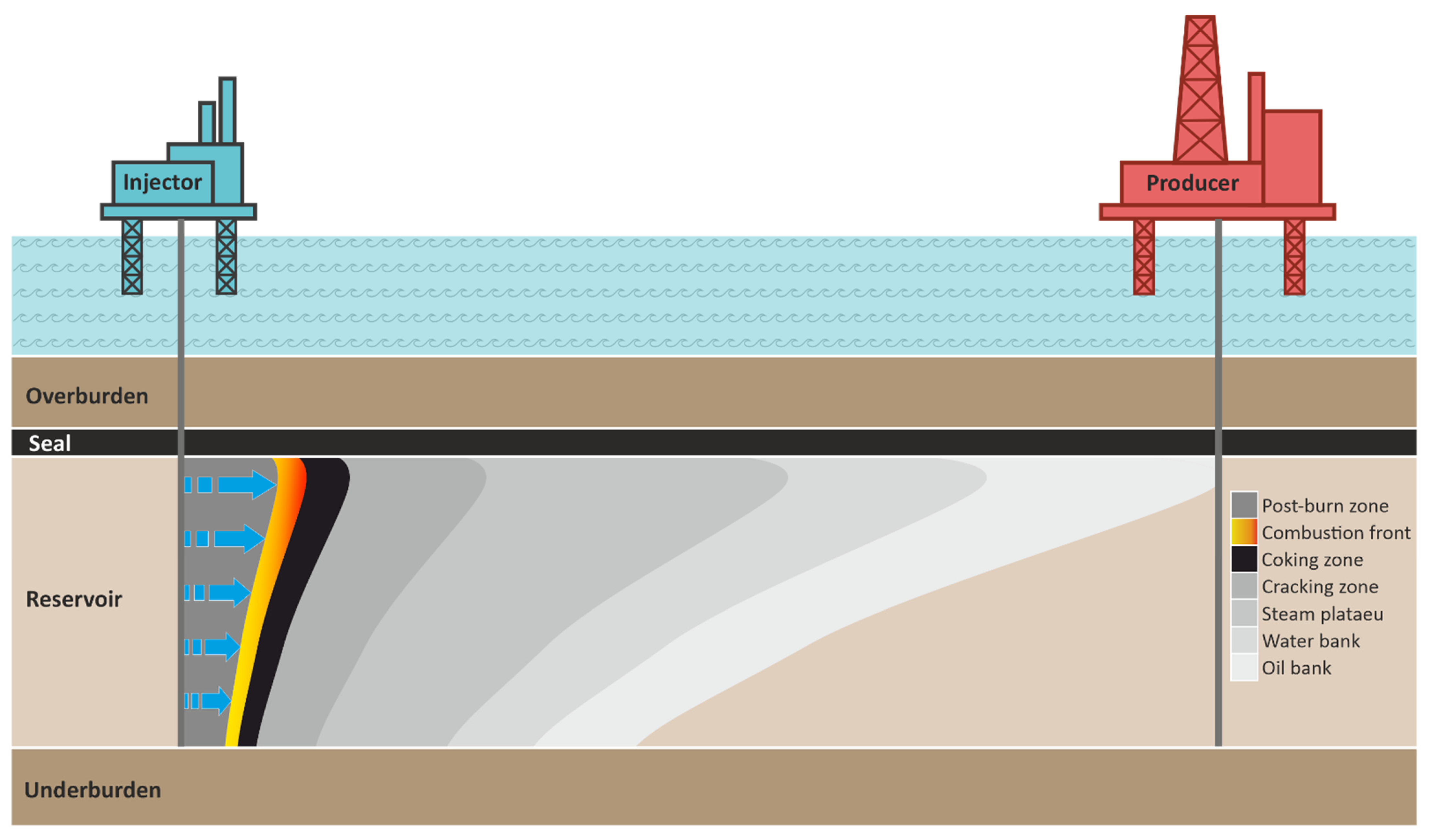
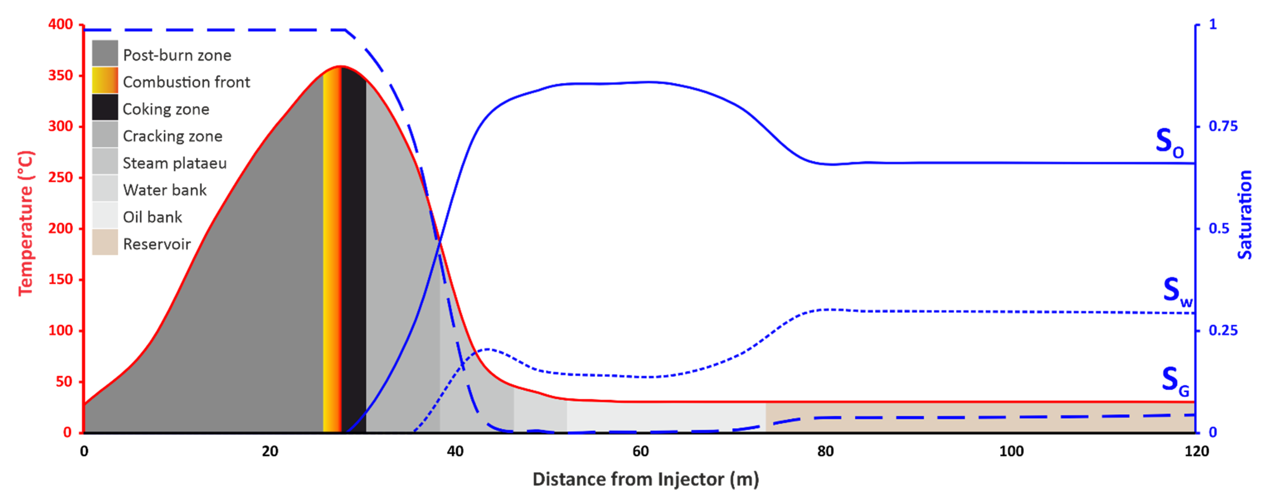
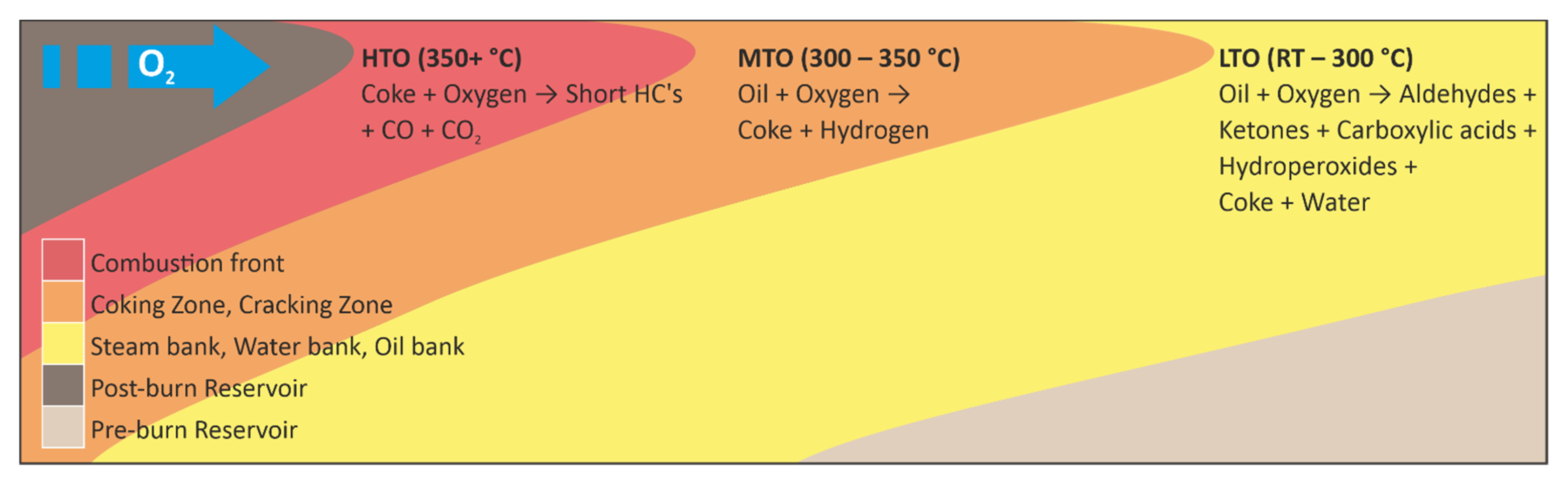
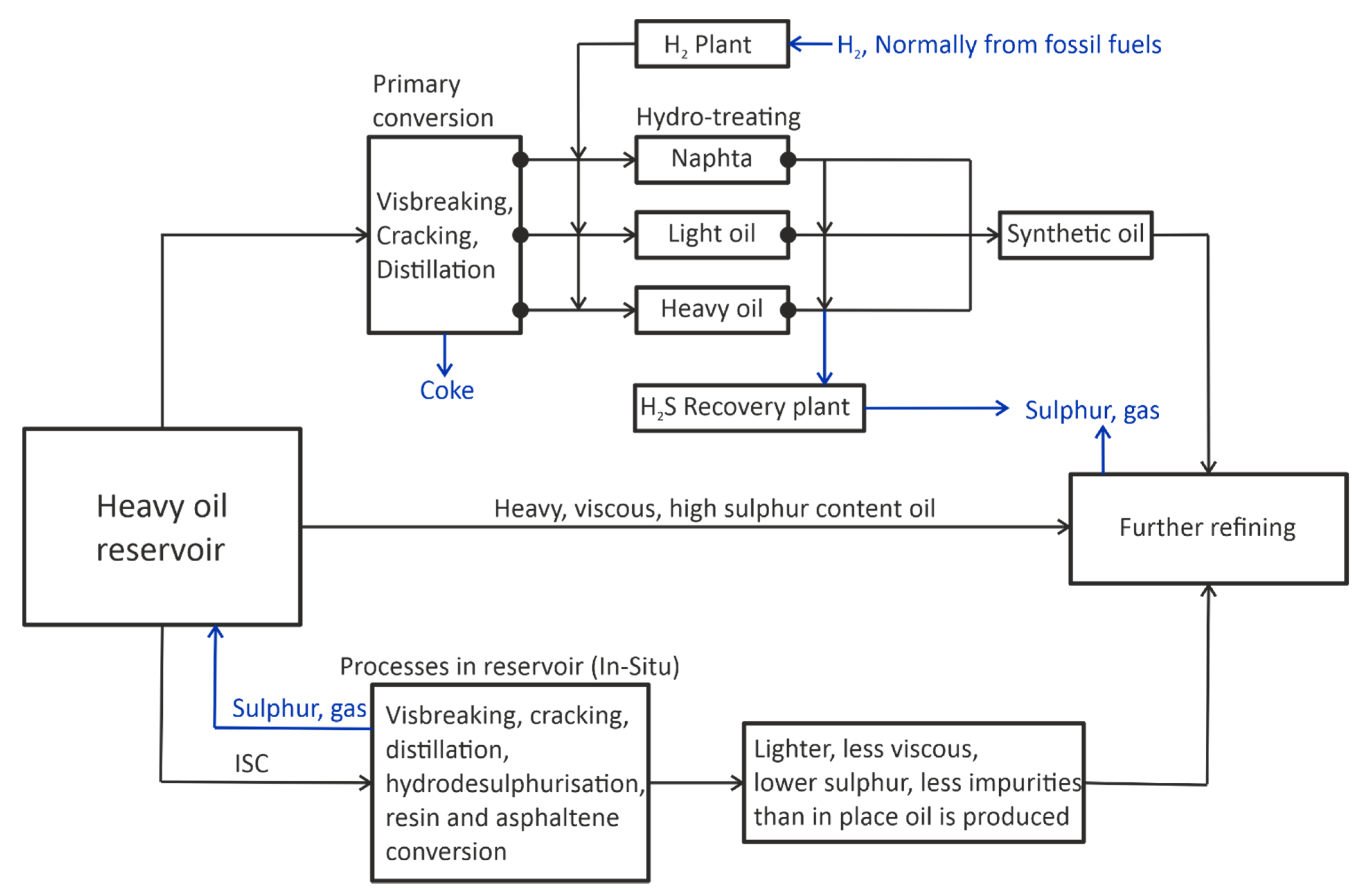
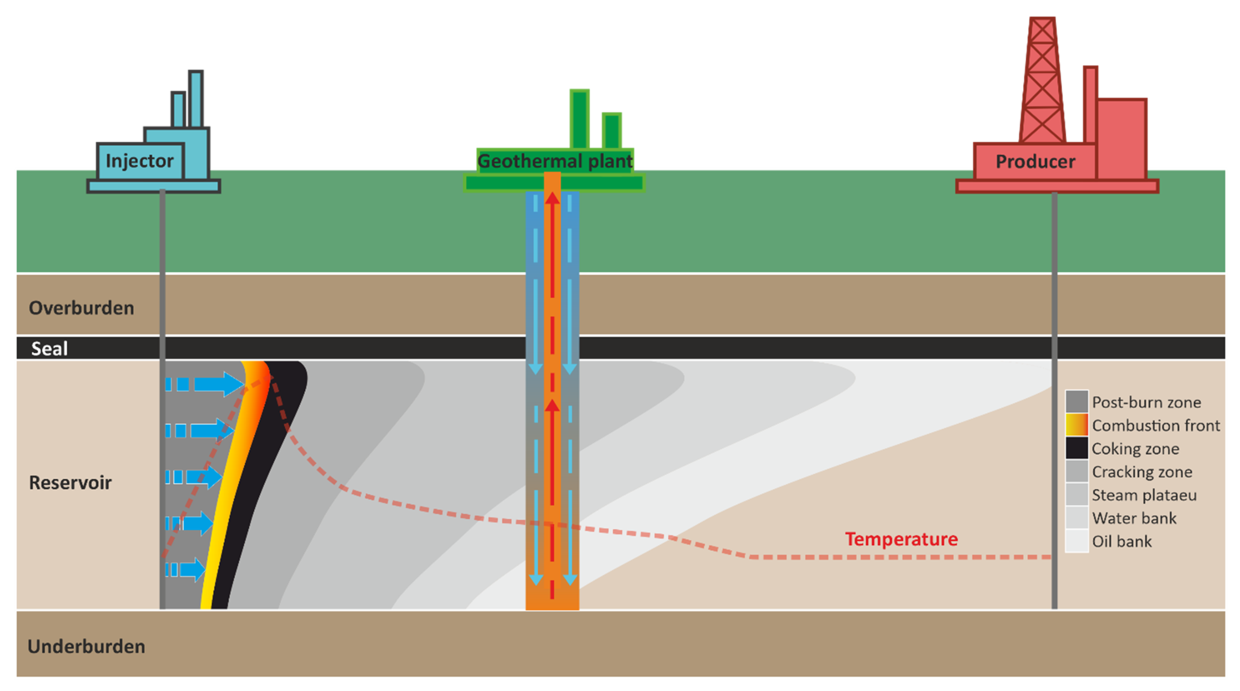
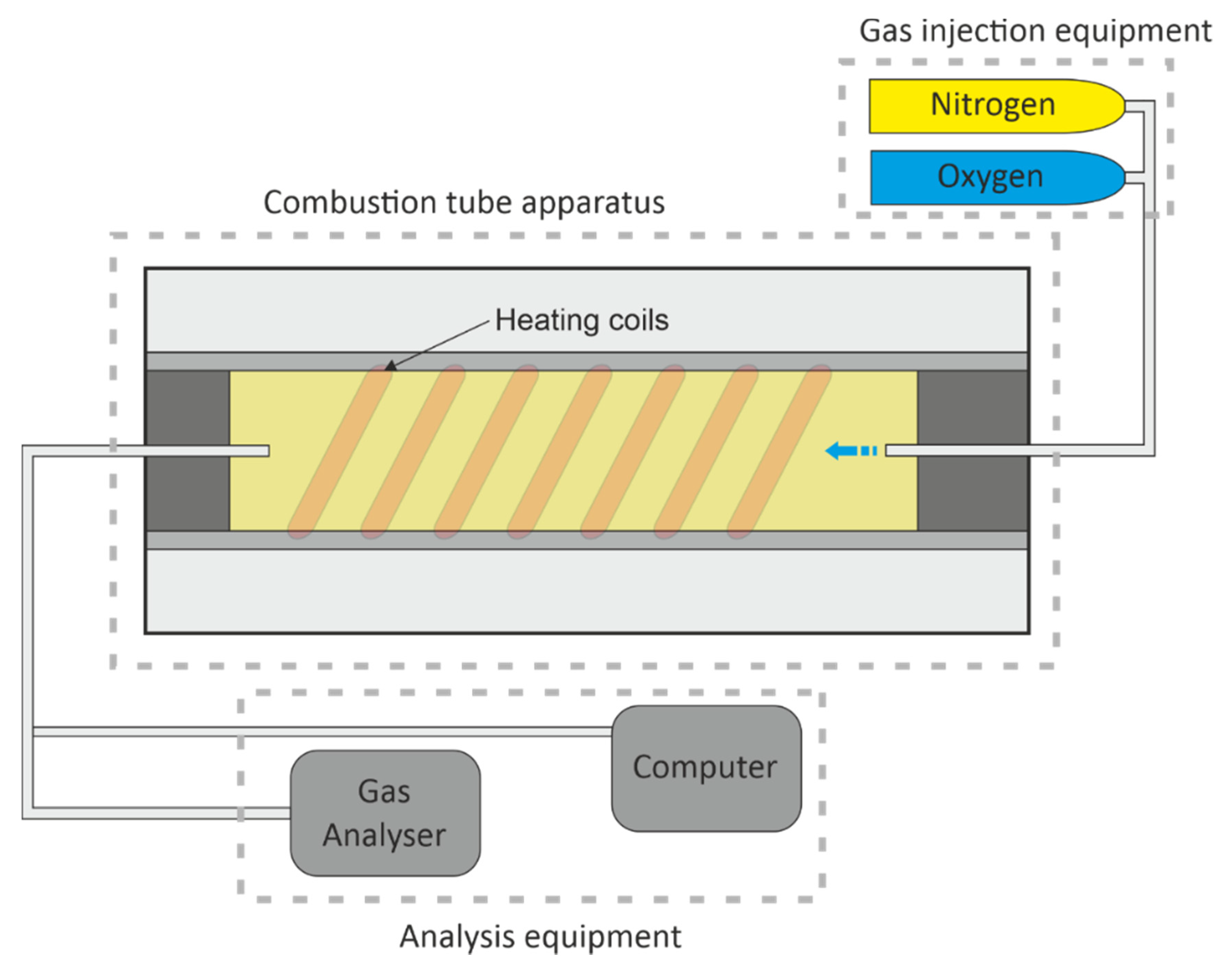
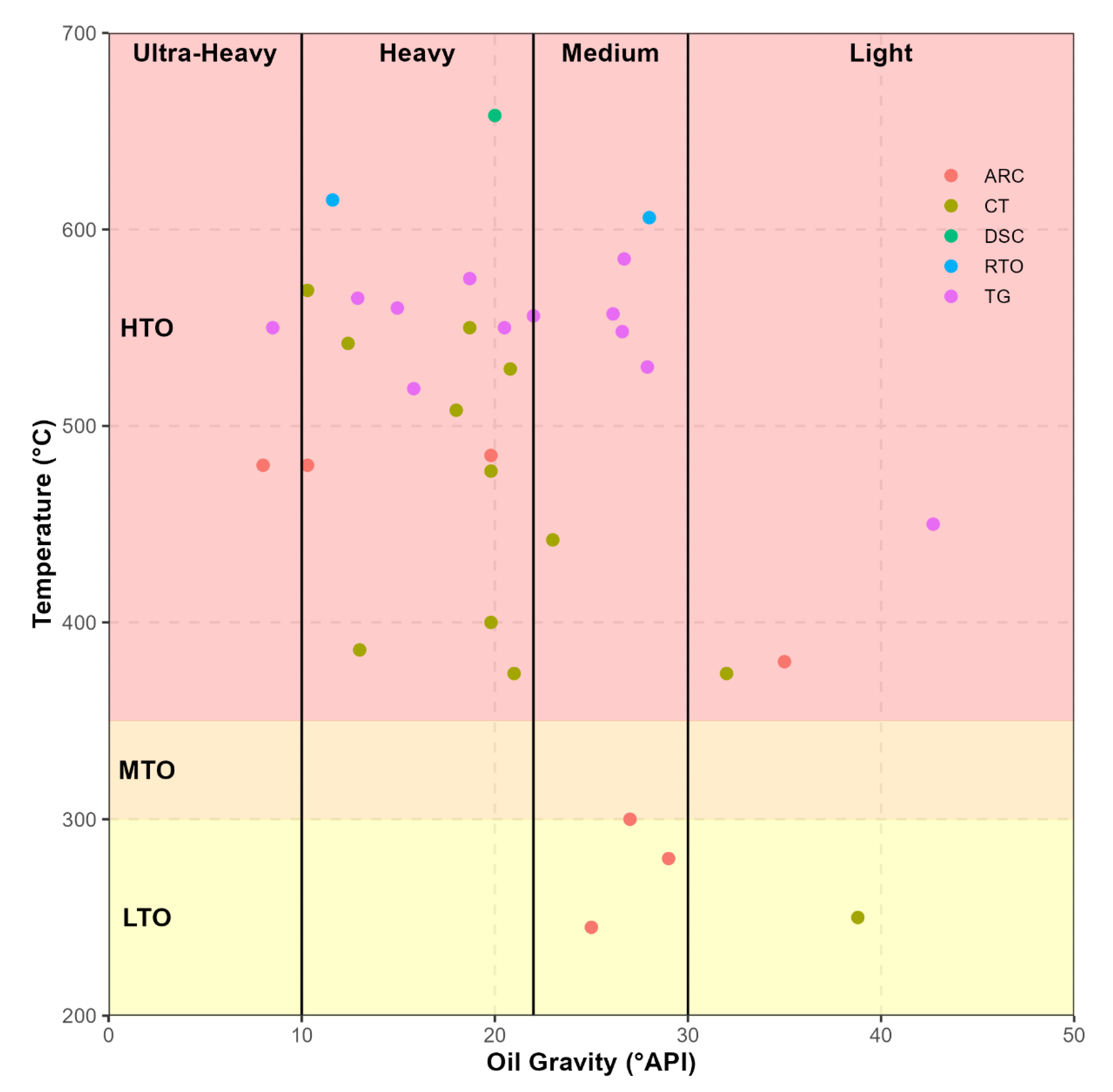
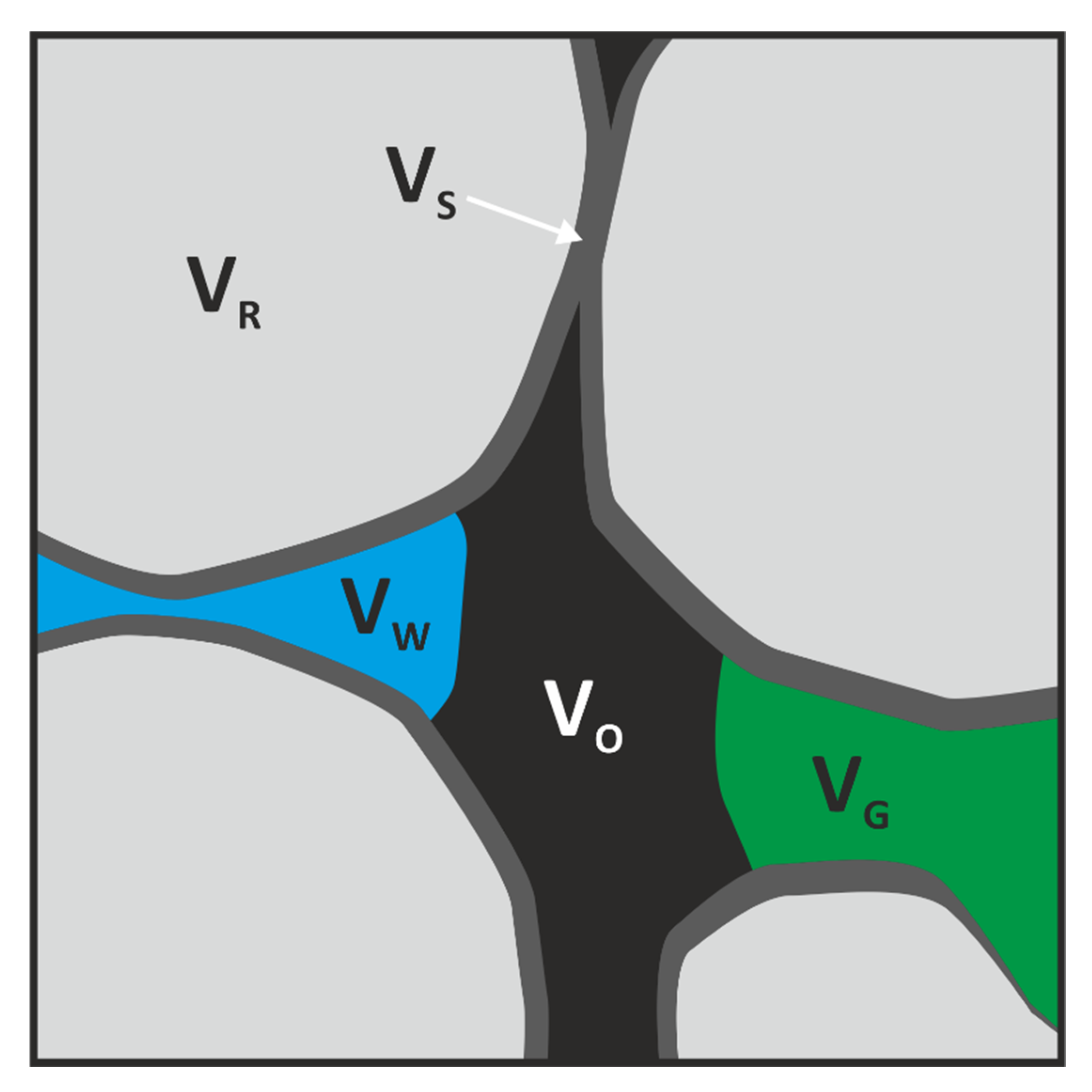
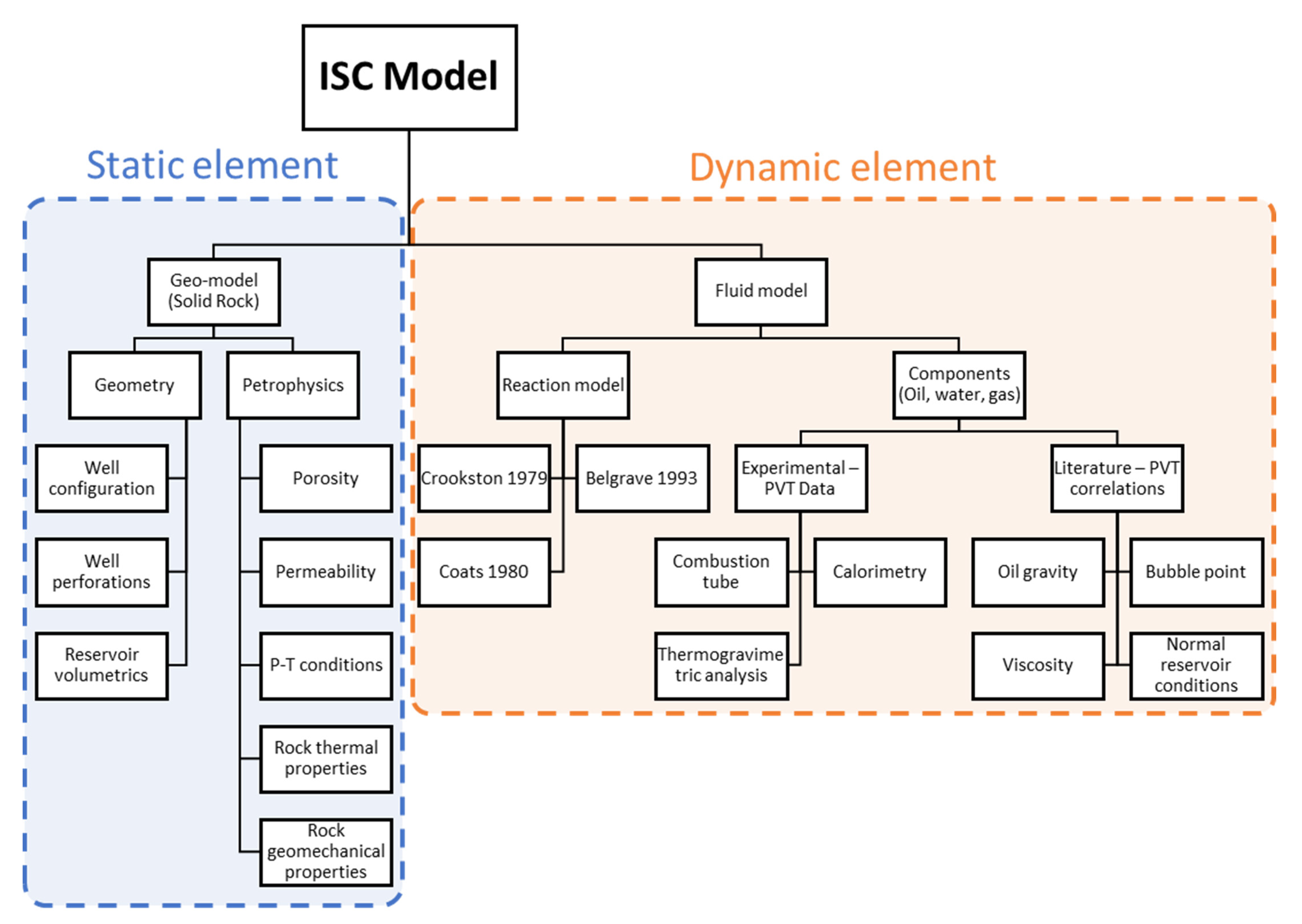
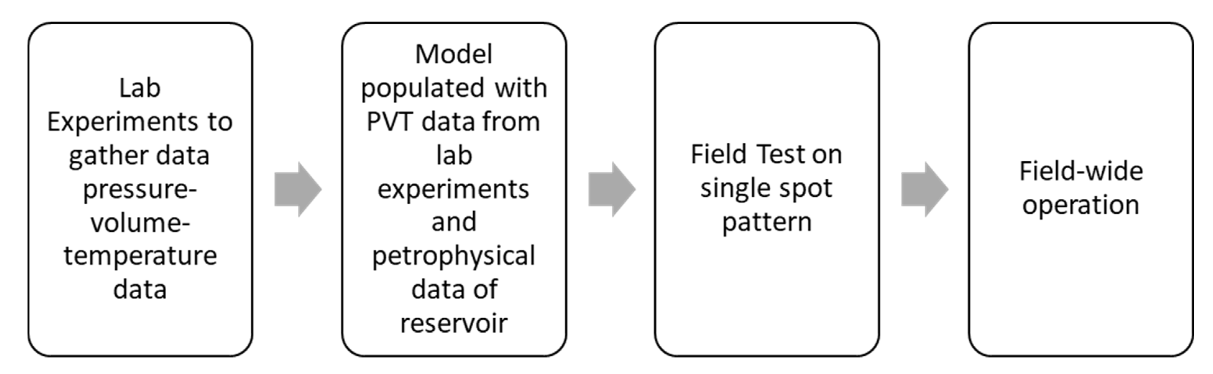
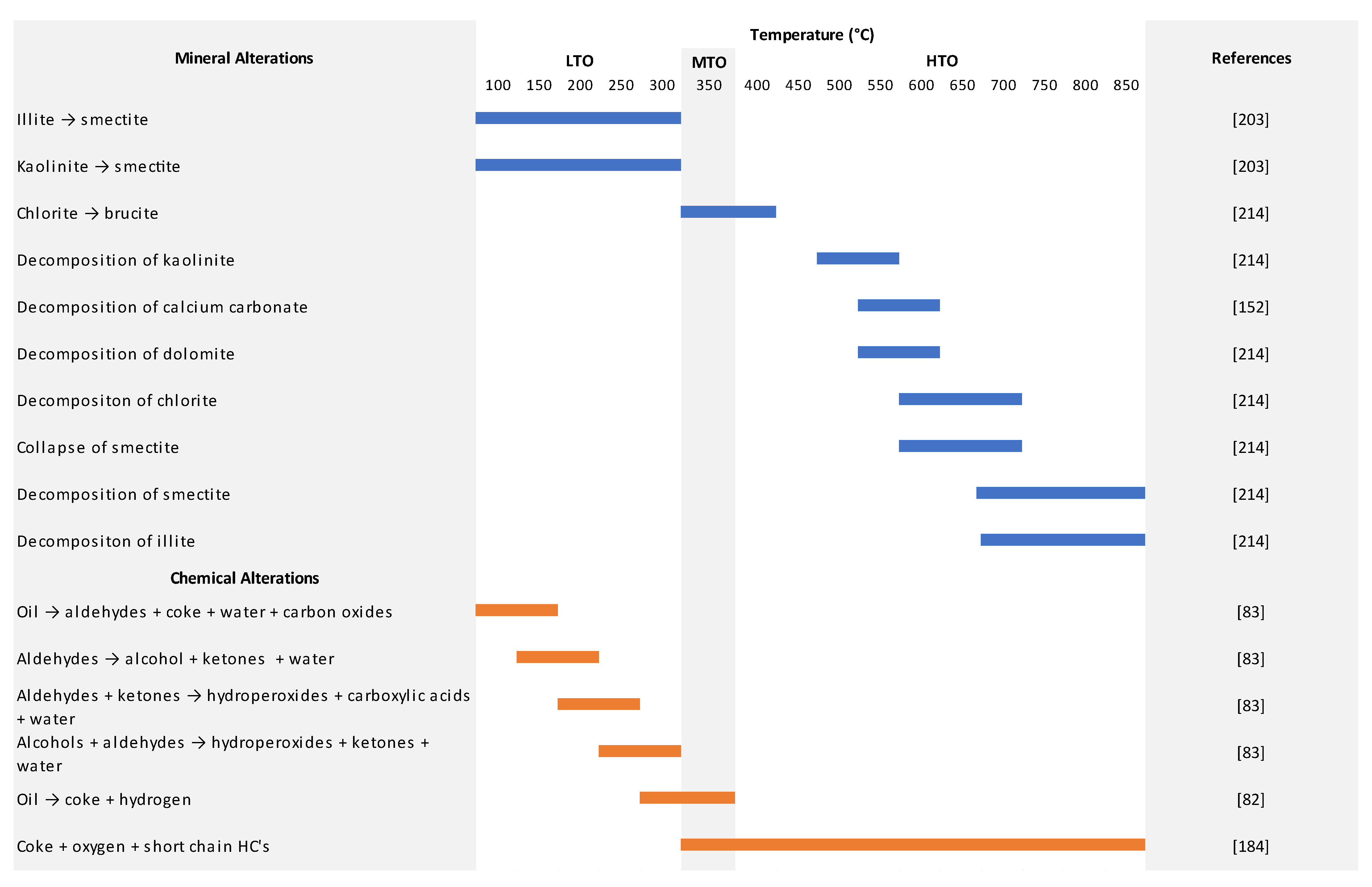
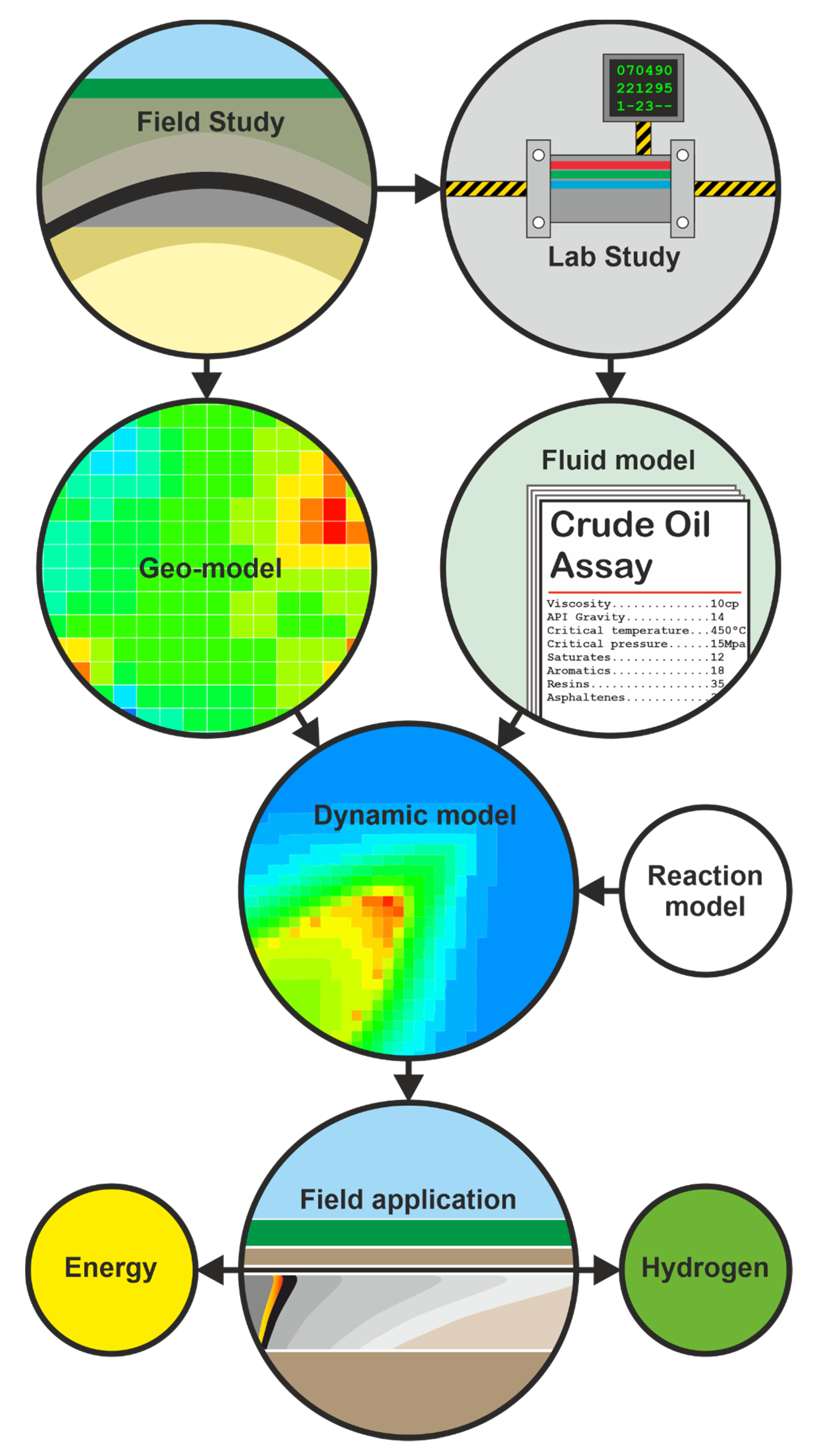
Author Contributions
Conceptualization, B.M.S. and R.H.W.; methodology, B.M.S. and R.H.W.; software, B.M.S.; validation, B.M.S., R.H.W. and D.D.M.; formal analysis, B.M.S., R.H.W. and D.D.M.; investigation, B.M.S.; resources, B.M.S.; data curation, B.M.S., R.H.W. and D.D.M.; writing—original draft preparation, B.M.S.; writing—review and editing, R.H.W. and D.D.M.; visualization, B.M.S., R.H.W. and D.D.M.; supervision, R.H.W. and D.D.M.; project administration, R.H.W.; funding acquisition, R.H.W. All authors have read and agreed to the published version of the manuscript.
Funding
This research was funded by the Low Carbon Eco Innovatory (LCEI).
Data Availability Statement
Not applicable.
Conflicts of Interest
There are no conflicts of interest.
References
- Wolcott, E.R. Method of Increasing the Yield of Oil Wells. U.S. Patent 1,457,479, 5 June 1923. [Google Scholar]
- Wu, C.H.; Fulton, P.F. Experimental simulation of the zones preceding the combustion front of an in-situ combustion process. Soc. Pet. Eng. J. 1971, 11, 38–46. [Google Scholar] [CrossRef]
- Burger, J.G. Chemical aspects of in-situ combustion—Heat of combustion and kinetics. Soc. Pet. Eng. J. 1972, 12, 410–422. [Google Scholar] [CrossRef]
- Turta, A.T.; Chattopadhyay, S.K.; Bhattacharya, R.N.; Condrachi, A.; Hanson, W. Current status of commercial in situ combustion projects worldwide. J. Can. Pet. Technol. 2007, 46, 8–14. [Google Scholar] [CrossRef]
- Akkutlu, I.Y.; Yortsos, Y.C. The dynamics of in-situ combustion fronts in porous media. Combust. Flame 2003, 134, 229–247. [Google Scholar] [CrossRef]
- Dong, X.; Liu, H.; Chen, Z.; Wu, K.; Lu, N.; Zhang, Q. Enhanced oil recovery techniques for heavy oil and oilsands reservoirs after steam injection. Appl. Energy 2019, 239, 1190–1211. [Google Scholar] [CrossRef]
- Speight, J.G. Thermal methods of recovery. In Heavy Oil Production Processes; Elsevier Science & Technology: Saint Louis, MO, USA, 2013; pp. 93–130. [Google Scholar]
- Speight, J.G. Heavy Oil Recovery and Upgrading; Gulf Professional Publishing: Cambridge, MA, USA, 2019. [Google Scholar]
- Dingley, A.J. The combustion recovery process—Principles and practice. J. Can. Pet. Technol. 1965, 4, 196–205. [Google Scholar] [CrossRef]
- Nwidee, L.N.; Theophilus, S.; Barifcani, A.; Sarmadivaleh, M.; Iglauer, S. EOR Processes, Opportunities and Technological Advancements. In Chemical Enhanced Oil Recovery (cEOR)—A Practical Overview; InTech: London, UK, 2016. [Google Scholar]
- Martin, W.L.; Alexander, J.D.; Dew, J.N. Process variables of in situ combustion. Trans. AIME 1958, 213, 28–35. [Google Scholar] [CrossRef]
- Razzaghi, S.; Kharrat, R.; Vossoughi, S.; Rashtchian, D. Feasibility study of auto ignition in in-situ combustion process. J. Jpn. Pet. Inst. 2008, 51, 287–297. [Google Scholar] [CrossRef]
- Li, Y.-B.; Pu, W.-F.; Zhao, J.-Y.; Zhao, Q.-N.; Sun, L.; Jin, F.-Y.; Zhao, J.-Z.; Zhou, W. Variation of reservoir fluid property during the high pressure air injection process. Int. J. Green Energy 2015, 13, 173–180. [Google Scholar] [CrossRef]
- Yuan, S.; Jiang, H.; Wang, B.; Li, J. Design of steam preheating and ignition program of in situ combustion. Energy Fuels 2017, 31, 8643–8647. [Google Scholar] [CrossRef]
- Huang, S.; Sheng, J.J.; Jiang, Q.; Liu, J. Screening of spontaneous ignition feasibility during air injection EOR process based on thermal experiments. Energies 2019, 12, 3687. [Google Scholar] [CrossRef]
- Yue, P.; Huang, S.; Zeng, F.; Sheng, J.J.; Jiang, Q. Experimental and mechanism study on crude oil spontaneous ignition during the air injection process. Energy Fuels 2020, 34, 7076–7084. [Google Scholar] [CrossRef]
- Perry, R.H.; Green, D.W.; Campbell, J.M. Reverse combustion—A new oil recovery technique. J. Pet. Technol. 1960, 12, 11–12. [Google Scholar] [CrossRef]
- Wilson, L.A.; Reed, R.L.; Reed, D.W.; Clay, R.R.; Harrison, N.H. Some effects of pressure on forward and reverse combustion. Soc. Pet. Eng. J. 1963, 3, 127–137. [Google Scholar] [CrossRef]
- Askarova, A.; Popov, E.; Ursenbach, M.; Moore, G.; Mehta, S.; Cheremisin, A. Experimental investigations of forward and reverse combustion for increasing oil recovery of a real oil field. Energies 2020, 13, 4581. [Google Scholar] [CrossRef]
- Dietz, D.N.; Weijdema, J. Wet and partially quenched combustion. J. Pet. Technol. 1968, 20, 411–415. [Google Scholar] [CrossRef]
- Beckers, H.L.; Harmsen, G.J. The effect of water injection on sustained combustion in a porous medium. Soc. Pet. Eng. J. 1970, 10, 145–163. [Google Scholar] [CrossRef]
- Smith, F.W.; Perkins, T.K. Experimental and numerical simulation studies of the wet combustion recovery process. J. Can. Pet. Technol. 1973, 12, 44–54. [Google Scholar] [CrossRef]
- Akin, S.; Bagci, S.; Kok, M.V. Experimental and numerical analysis of dry forward combustion with diverse well configuration. Energy Fuels 2002, 16, 892–903. [Google Scholar] [CrossRef]
- Alamatsaz, A.; Moore, G.R.; Mehta, S.A.; Ursenbach, M.G. Analysis of dry, wet and superwet in situ combustion using a novel conical cell experiment. Fuel 2018, 234, 482–491. [Google Scholar] [CrossRef]
- Attanasi, E.D.; Meyer, R.F. Heavy oil and natural bitumen; strategic petroleum resources. Fact Sheet U.S. Geol. Surv. 2003. [Google Scholar] [CrossRef]
- Greaves, M.; Young, T.J.; El-Usta, S.; Rathbone, R.R.; Ren, S.R.; Xia, T.X. Air injection into light and medium heavy oil reservoirs. Chem. Eng. Res. Des. 2000, 78, 721–730. [Google Scholar] [CrossRef]
- Kumar, V.K.; Fassihi, M.R.; Yannimaras, D.V. Case history and appraisal of the Medicine Pole Hills unit air-injection project. Soc. Pet. Eng. Reserv. Eng. 1995, 10, 198–202. [Google Scholar] [CrossRef]
- Moore, R.G.; Mehta, S.A.; Ursenbach, M.G. A guide to high pressure air injection (HPAI) based oil recovery. In Proceedings of the Society of Petroleum Engineers/DOE Improved Oil Recovery Symposium, Tulsa, OK, USA, 13–17 April 2002. [Google Scholar]
- Gutiérrez, D.; Miller, R.J.; Taylor, A.R.; Thies, B.P.; Kumar, V.K. Buffalo Field high-pressure-air-injection projects: Technical performance and operational challenges. Soc. Pet. Eng. Reserv. Eval. Eng. 2009, 12, 542–550. [Google Scholar] [CrossRef]
- Pu, W.; Liu, Z.; Li, Y.; Wei, B.; Jia, H.; Kong, L. A novel insight of laboratory investigation and simulation for high pressure air injection in light oil reservoir. J. Nat. Gas Sci. Eng. 2017, 38, 333–344. [Google Scholar] [CrossRef]
- Gargar, N.K.; Bruining, J.; Kokubun, M.A.E.; Marchesin, D.; Mailybaev, A.A. Combustion in miscible displacement for high-pressure air injection. Comput. Geosci. 2020, 24, 1663–1672. [Google Scholar] [CrossRef]
- Khakimova, L.; Askarova, A.; Popov, E.; Moore, R.G.; Solovyev, A.; Simakov, Y.; Afanasiev, I.; Belgrave, J.; Cheremisin, A. High-pressure air injection laboratory-scale numerical models of oxidation experiments for Kirsanovskoye oil field. J. Pet. Sci. Eng. 2020, 188, 106796. [Google Scholar] [CrossRef]
- Erickson, A.; Legerski, J.R.; Steece, F.V. An appraisal of high pressure air injection (HPAI) on the in situ combustion results from deep, high temperature, high gravity oil reservoirs. In Wyoming Geological Society Guidebook; Wyoming Geological Society: Casper, WY, USA, 1993; pp. 259–270. [Google Scholar]
- Denney, D. 30 years of successful high-pressure air injection: Performance evaluation of Buffalo Field, South Dakota. J. Pet. Technol. 2011, 63, 50–53. [Google Scholar] [CrossRef]
- Anthony, M.J.; Taylor, T.D.; Gallagher, B.J. Fireflooding a high-gravity crude in a watered-out West Texas sandstone. J. Pet. Technol. 1982, 34, 2244–2250. [Google Scholar] [CrossRef]
- Ling, K.; Shen, Z.; Han, G.; He, J. A review of enhanced oil recovery methods applied in Williston Basin. In Proceedings of the 2nd Unconventional Resources Technology Conference, Denver, CO, USA, 25–27 August 2014. [Google Scholar]
- Gutiérrez, D.; Taylor, A.R.; Kumar, V.K.; Ursenbach, M.G.; Moore, R.G.; Mehta, S.A. Recovery factors in high-pressure air injection projects revisited. Soc. Pet. Eng. Reserv. Eval. Eng. 2008, 11, 1097–1106. [Google Scholar] [CrossRef]
- Kovscek, A.R.R.; Castanier, L.M.M.; Gerritsen, M.G.G. Improved predictability of in-situ-combustion enhanced oil recovery. Soc. Pet. Eng. Reserv. Eval. Eng. 2013, 16, 172–182. [Google Scholar] [CrossRef]
- Zhang, X.; Liu, Q.; Fan, Z.; Liu, Q. An in situ combustion process for recovering heavy oil using scaled physical model. J. Pet. Explor. Prod. Technol. 2019, 9, 2681–2688. [Google Scholar] [CrossRef]
- Xia, T.X.; Greaves, M.; Turta, A.T.; Ayasse, C. THAI—A ‘short-distance displacement’ in situ combustion process for the recovery and upgrading of heavy oil. Chem. Eng. Res. Des. 2003, 81, 295–304. [Google Scholar] [CrossRef]
- Castanier, L.M.; Brigham, W.E. Upgrading of crude oil via in situ combustion. J. Pet. Sci. Eng. 2003, 39, 125–136. [Google Scholar] [CrossRef]
- Gates, I.D.; Chakrabarty, N.; Moore, R.G.; Mehta, S.A.; Zalewski, E.; Pereira, P. In-situ upgrading of Llancanelo heavy oil using in situ combustion and a downhole catalyst bed. J. Can. Pet. Technol. 2008, 47, 23–31. [Google Scholar] [CrossRef]
- Kapadia, P.R.; Kallos, M.S.; Gates, I.D. Potential for hydrogen generation from in situ combustion of Athabasca bitumen. Fuel 2011, 90, 2254–2265. [Google Scholar] [CrossRef]
- Kapadia, P.R.; Wang, J.; Kallos, M.S.; Gates, I.D. Practical process design for in situ gasification of bitumen. Appl. Energy 2013, 107, 281–296. [Google Scholar] [CrossRef]
- Kapadia, P.R.; Kallos, M.S.; Gates, I.D. A review of pyrolysis, aquathermolysis, and oxidation of Athabasca bitumen. Fuel Processing Technol. 2015, 131, 270–289. [Google Scholar] [CrossRef]
- Hart, A.; Wood, J.; Greaves, M. Laboratory investigation of CAPRI catalytic THAI-add-on process for heavy oil production and in situ upgrading. J. Anal. Appl. Pyrolysis 2017, 128, 18–26. [Google Scholar] [CrossRef]
- Li, Y.; Wang, Z.; Hu, Z.; Xu, B.; Li, Y.; Pu, W.; Zhao, J. A review of in situ upgrading technology for heavy crude oil. Petroleum 2021, 7, 117–122. [Google Scholar] [CrossRef]
- Cinar, M. Creating enhanced geothermal systems in depleted oil reservoirs via in situ combustion. In Proceedings of the Thirty-Eigth Workshop on Geothermal Reservoir Enginerring, Stanford, CA, USA, 11–13 February 2013. [Google Scholar]
- Li, T.; Zhu, J.; Xin, S.; Zhang, W. A novel geothermal system combined power generation, gathering heat tracing, heating/domestic hot water and oil recovery in an oilfield. Geothermics 2014, 51, 388–396. [Google Scholar] [CrossRef]
- Zhu, Y.; Li, K.; Liu, C.; Mgijimi, M.B. Geothermal power production from abandoned oil reservoirs using in situ combustion technology. Energies 2019, 12, 4476. [Google Scholar] [CrossRef]
- Han, Y.; Li, K.; Jia, L. Modeling study on reviving abandoned oil reservoirs by in situ combustion without CO2 production while recovering both oil and heat. J. Energy Resour. Technol. 2021, 143, 082902. [Google Scholar] [CrossRef]
- Hajdo, L.E.; Hallam, R.J.; Vorndran, L.D.L. Hydrogen generation during in-situ combustion. In Proceedings of the Society of Petroleum Engineers 1985 California Regional Meeting, Bakersfield, CA, USA, 27–29 March 1985. [Google Scholar]
- Kapadia, P.R.; Kallos, M.; Chris, L.; Gates, I.D. Potential for hydrogen generation during in-situ combustion of bitumen. In Proceedings of the Society of Petroleum Engineers EUROPEC/EAGE Annual Conference and Exhibition, Amsterdam, The Netherlands, 8–11 June 2009. [Google Scholar]
- Cheng, W.-L.; Li, T.-T.; Nian, Y.-L.; Xie, K. Evaluation of working fluids for geothermal power generation from abandoned oil wells. Appl. Energy 2014, 118, 238–245. [Google Scholar] [CrossRef]
- Davis, A.P.; Michaelides, E.E. Geothermal power production from abandoned oil wells. Energy 2009, 34, 866–872. [Google Scholar] [CrossRef]
- Counihan, T.M. A successful in-situ combustion pilot In the Midway-Sunset Field, California. In Proceedings of the 47th Annual California Regional Meeting of the Society of Petroleum Engineers of AIME, Bakersfield, CA, USA, 13–15 April 1977. [Google Scholar]
- Feng, T.; Wu, Y.; Hu, C.; Gong, Y.; Song, Y. Technology of fire flooding process control: Application to fire flooding in a deep and thick heavy oil reservoir in China. In Proceedings of the Society of Petroleum Engineers Asia Pacific Oil & Gas Conference and Exhibition, Brisbane, QLD, Australia, 23–25 October 2018. [Google Scholar]
- Feng, T.; Wu, Y.; Song, Y. Key technologies for fire flooding in thin interbeded heavy oil reservoirs. In Proceedings of the SPE Middle East Oil and Gas Show and Conference, Manama, Bahrain, 18–21 March 2019. [Google Scholar]
- Sharma, J.; Dean, J.; Aljaberi, F.; Altememee, N. In-situ combustion in Bellevue field in Louisiana—History, current state and future strategies. Fuel 2021, 284, 118992. [Google Scholar] [CrossRef]
- Alexander, J.D.; Martin, W.L.; Dew, J.N. Factors affecting fuel availability and composition during in situ combustion. J. Pet. Technol. 1962, 14, 1154–1164. [Google Scholar] [CrossRef]
- Belgrave, J.D.M.; Moore, R.G. A model for improved analysis of in-situ combustion tube tests. J. Pet. Sci. Eng. 1992, 8, 75–88. [Google Scholar] [CrossRef]
- Klock, K.; Hascakir, B. Simplified reaction kinetics model for in-situ combustion. In Proceedings of the PE Latin American and Caribbean Petroleum Engineering Conference, Quito, Ecuador, 18–20 November 2015. [Google Scholar]
- Aleksandrov, D.; Kudryavtsev, P.; Hascakir, B. Variations in in-situ combustion performance due to fracture orientation. J. Pet. Sci. Eng. 2017, 154, 488–494. [Google Scholar] [CrossRef]
- Genrich, J.F.; Pope, G.A. A simplified performance-predictive model for in-situ combustion processes. Soc. Pet. Eng. Reserv. Eng. 1988, 3, 410–418. [Google Scholar] [CrossRef]
- Ahmadi, M.A.; Masoumi, M.; Askarinezhad, R. Evolving connectionist model to monitor the efficiency of an in situ combustion process: Application to heavy oil recovery. Energy Technol. 2014, 2, 811–818. [Google Scholar] [CrossRef]
- Ado, M.R. Effect of reservoir pay thickness on the performance of the THAI heavy oil and bitumen upgrading and production process. J. Pet. Explor. Prod. Technol. 2020, 10, 2005–2018. [Google Scholar] [CrossRef]
- Sarathi, P. Environmental aspects of heavy-oil recovery by thermal EOR processes. J. Pet. Technol. 1991, 43, 662–721. [Google Scholar] [CrossRef]
- Sarathi, P.S. In-situ Combustion Handbook—Principles and Practices; Office of Scientific and Technical Information (OSTI): Tulsa, OK, USA, 1999. [Google Scholar]
- Bagci, S.; Shamsul, A. A comparison of dry forward combustion with diverse well configurations in a 3D physical model using medium and low gravity crudes. J. Can. Pet. Technol. 1999, 38, 50–51. [Google Scholar] [CrossRef]
- Joseph, C.; Jay, C.B.; Eslinger, E.V. Evaluation of an in-situ combustion process by postburn core and log analysis. J. Pet. Technol. 1983, 35, 827–835. [Google Scholar] [CrossRef]
- Paitakhti Oskouei, S.J.; Moore, G.; Maini, B.B.; Mehta, S.A. Front self-correction for in-situ combustion. J. Can. Pet. Technol. 2011, 50, 43–56. [Google Scholar] [CrossRef]
- Gates, C.F.; Sklar, I. Combustion as a primary recovery process—Midway Sunset Field. J. Pet. Technol. 1971, 23, 981–986. [Google Scholar] [CrossRef]
- Amrollahi Biyouki, A.; Hosseinpour, N.; Nassar, N.N. Pyrolysis and oxidation of asphaltene-born coke-like residue formed onto in situ prepared NiO nanoparticles toward advanced in situ combustion enhanced oil recovery processes. Energy Fuels 2018, 32, 5033–5044. [Google Scholar] [CrossRef]
- Dabbous, M.K.; Fulton, P.F. Low-temperature-oxidation reaction kinetics and effects on the in-situ combustion process. Soc. Pet. Eng. AIME J. 1974, 14, 253–262. [Google Scholar] [CrossRef]
- Ranjbar, M. Improvement of medium and light oil recovery with thermocatalytic in situ combustion. J. Can. Pet. Technol. 1995, 34, 25–30. [Google Scholar] [CrossRef]
- Adagulu, G.D.; Akkutlu, I.Y. Influence of in-situ fuel deposition on air injection and combustion processes. J. Can. Pet. Technol. 2007, 46, 54–61. [Google Scholar] [CrossRef]
- Cinar, M.; Hasçakir, B.; Castanier, L.M.; Kovscek, A.R. Predictability of crude oil in-situ combustion by the isoconversional kinetic approach. Soc. Pet. Eng. J. 2011, 16, 537–547. [Google Scholar] [CrossRef]
- Gargar, N.K.; Mailybaev, A.A.; Marchesin, D.; Bruining, H. Compositional effects in light/medium oil recovery by air injection: Vaporization vs. Combustion. J. Porous Media 2014, 17, 937–952. [Google Scholar] [CrossRef]
- Yuan, C.; Sadikov, K.; Varfolomeev, M.; Khaliullin, R.; Pu, W.; Al-Muntaser, A.; Saeed Mehrabi-Kalajahi, S. Low-temperature combustion behavior of crude oils in porous media under air flow condition for in-situ combustion (ISC) process. Fuel 2020, 259, 116293. [Google Scholar] [CrossRef]
- Fassihi, M.R.; Meyers, K.O.; Baslle, P.F. Low-temperature oxidation of viscous crude oils. Soc. Pet. Eng. Reserv. Eng. 1990, 5, 609–616. [Google Scholar] [CrossRef]
- Fassihi, M.R.; Brigham, W.E.; Ramey, H.J. Reaction kinetics of in-situ combustion: Part 1—Observations. Soc. Pet. Eng. J. 1984, 24, 399–407. [Google Scholar] [CrossRef]
- Chavez, M.-L.R.; Glatz, G.; Clemens, T.; Kovscek, A. Near-wellbore and reservoir effects in in-situ combustion. Soc. Pet. Eng. Reserv. Eval. Eng. 2016, 20, 698–707. [Google Scholar] [CrossRef]
- Khansari, Z.; Kapadia, P.; Mahinpey, N.; Gates, I.D. A new reaction model for low temperature oxidation of heavy oil: Experiments and numerical modeling. Energy 2014, 64, 419–428. [Google Scholar] [CrossRef]
- Fassihi, M.R.; Yannimaras, D.V.; Westfall, E.E.; Gillham, T.H. Economics of light oil air injection projects. In Proceedings of the Society of Petroleum Engineers/DOE Improved Oil Recovery Symposium, Tulsa, OK, USA, 21–24 April 1996; pp. 501–509. [Google Scholar]
- Ranjbar, M.; Pusch, G. Pyrolysis and combustion kinetics of crude oils, asphaltenes and resins in relation to thermal recovery processes. J. Anal. Appl. Pyrolysis 1991, 20, 185–196. [Google Scholar] [CrossRef]
- Ren, S.R.; Greaves, M.; Rathbone, R.R. Air injection LTO Process: An IOR technique for light-oil reservoirs. Soc. Pet. Eng. J. 2002, 7, 90–99. [Google Scholar] [CrossRef]
- Mahinpey, N.; Ambalae, A.; Asghari, K. In situ combustion in enhanced oil recovery (EOR): A review. Chem. Eng. Commun. 2007, 194, 995–1021. [Google Scholar] [CrossRef]
- Babadagli, T. Philosophy of EOR. In Proceedings of the SPE/IATMI Asia Pacific Oil & Gas Conference and Exhibition, Bali, Indonesia, 29–31 October 2019. [Google Scholar]
- Hart, A.; Adam, M.; Robinson, J.P.; Rigby, S.P.; Wood, J. Inductive heating assisted-catalytic dehydrogenation of tetralin as a hydrogen source for downhole catalytic upgrading of heavy oil. Top. Catal. 2019, 63, 268–280. [Google Scholar] [CrossRef]
- Ali, S.M.F. Current status of in-situ recovery from the tar sands of Alberta. J. Can. Pet. Technol. 1975, 14, PETSOC-75-01-05. [Google Scholar] [CrossRef]
- Greaves, M.; Ren, S.R.; Rathbone, R.R.; Fishlock, T.; Ireland, R. Improved residual light oil recovery by air injection (LTO process). J. Can. Pet. Technol. 2000, 39, 57–61. [Google Scholar] [CrossRef]
- Pu, W.; Zhao, S.; Hu, L.; Varfolomeev, M.A.; Yuan, C.; Wang, L.; Rodionov, N.O. Thermal effect caused by low temperature oxidation of heavy crude oil and its in-situ combustion behavior. J. Pet. Sci. Eng. 2020, 184, 106521. [Google Scholar] [CrossRef]
- Bu, X.; Ma, W.; Li, H. Geothermal energy production utilizing abandoned oil and gas wells. Renew. Energy 2012, 41, 80–85. [Google Scholar] [CrossRef]
- Li, K.; Zhang, L. Exceptional enhanced geothermal systems from oil and gas reservoirs. In Proceedings of the Thirty-Third Workshop on Geothermal Reservoir Engineering, Stanford, CA, USA, 28–30 January 2008. [Google Scholar]
- Moss, J.T.; White, P.D.; McNiel, J.S. In situ combustion process—Results of a five-well field experiment in Southern Oklahoma. Trans. AIME 1959, 216, 55–64. [Google Scholar] [CrossRef]
- Farquharson, R.G.; Thornton, R.W. Lessons from Eyehill. J. Can. Pet. Technol. 1986, 25, 47–53. [Google Scholar] [CrossRef]
- International Energy Agency. World Energy Outlook 2018—Analysis; International Energy Agency: Paris, France, 2018. [Google Scholar]
- Tennyson, M.E. Growth history of oil reserves in major california oil fields during the twentieth century. In Geologic, Engineering, and Assessment Studies of Reserve Growth; USGS: Reston, VA, USA, 2005; p. 5. [Google Scholar]
- Fassihi, M.R.; Yannimaras, D.V.; Kumar, V.K. Estimation of recovery factor in light-oil air-injection projects. Soc. Pet. Eng. Reserv. Eng. 1997, 12, 173–178. [Google Scholar] [CrossRef]
- Struna, S.M.; Poettmann, F.H. In-situ combustion in the Lower Hospah Formation, McKinley County, New Mexico. Soc. Pet. Eng. Reserv. Eng. 1988, 3, 440–448. [Google Scholar] [CrossRef]
- Clark, G.A.; Jones, R.G.; Kinney, W.L.; Schilson, R.E.; Surkalo, H.; Wilson, R.S. The fry in situ combustion test-field operations. J. Pet. Technol. 1965, 17, 343–347. [Google Scholar] [CrossRef]
- Earlougher, R.C.; Galloway, J.R.; Parsons, R.W. Performance of the Fry in-situ combustion project. J. Pet. Technol. 1970, 22, 551–557. [Google Scholar] [CrossRef]
- Hewitt, C.H.; Morgan, J.T. The Fry in situ combustion test-reservoir characteristics. J. Pet. Technol. 1965, 17, 337–342. [Google Scholar] [CrossRef]
- Clark, G.A.; Jones, R.G.; Kinney, W.L.; Schilson, R.E.; Surkalo, H.; Wilson, R.S. The fry in situ combustion test-performance. J. Pet. Technol. 1965, 17, 348–353. [Google Scholar] [CrossRef]
- Turta, A.; Kapadia, P.; Gadelle, C. THAI process: Determination of the quality of burning from gas composition taking into account the coke gasification and water-gas shift reactions. J. Pet. Sci. Eng. 2020, 187, 106638. [Google Scholar] [CrossRef]
- Abu, I.I.; Moore, R.G.; Mehta, S.A.; Ursenbach, M.G.; Mallory, D.G.; Pereira Almao, P.; Carbognani Ortega, L. Upgrading of Athabasca bitumen using supported catalyst in conjunction with in-situ combustion. J. Can. Pet. Technol. 2015, 54, 220–232. [Google Scholar] [CrossRef]
- Liu, G.; Zhang, T.; Xie, Q.; Liu, W.; Wang, L.; Yang, D. Experimental evaluation of live oil oxidation together with its physical properties during air injection in a tight oil reservoir. Fuel 2021, 283. [Google Scholar] [CrossRef]
- Zhang, Y.; Zhang, X.; Hower, J.C.; Hu, S. Mineralogical and geochemical characteristics of pyrometamorphic rocks induced by coal fires in Junggar Basin, Xinjiang, China. J. Geochem. Explor. 2020, 213, 106511. [Google Scholar] [CrossRef]
- Yao, J.; Li, G.; Wu, J. Application of In-situ combustion for heavy oil production in China: A Review. J. Oil Gas Petrochem. Sci. 2018, 1, 69–72. [Google Scholar] [CrossRef]
- Al-Mahasneh, M.A. Toe-to-heel air injection in-situ combustion process: Case study from the Azraq Basin, Jordan. Rud.-Geološko-Naft. Zb. 2020, 35, 77–84. [Google Scholar] [CrossRef]
- Turta, A.T.; Pantazi, I.G. Development of the in-situ combustion process on an industrial scale at Videle Field, Rumania. Soc. Pet. Eng. Reserv. Eng. 1986, 1, 556–564. [Google Scholar] [CrossRef]
- Adabala, D.; Ray, S.P.; Gupta, P.K. In-situ combustion technique to enhance heavy oil recovery at Mehsana, ONGC—A success story. In Proceedings of the 15th SPE Middle East Oil & Gas Show and Conference, Sanabis, Bahrain, 11–14 March 2007. [Google Scholar]
- Dayal, H.S.; Bhushan, B.V.; Mitra, S.; Pandey, V.; Bhandari, A.C.; Dwivedi, M.M. Simulation of in-situ combustion process in Balol Pilot. In Proceedings of the PE Oil and Gas India Conference and Exhibition, Mumbai, India, 28–30 March 2012. [Google Scholar]
- Horne, J.; Bousaid, I.; Dore, T.L.; Smith, L.B. Initiation of an in-situ combustion project in a thin oil column underlain by water. J. Pet. Technol. 1982, 34, 2233–2243. [Google Scholar] [CrossRef]
- Widmyer, R.H.; Howard, C.E.; Fontaine, M.F.; Haynes, S. The Charco Redondo thermal recovery pilot. J. Pet. Technol. 1977, 29, 1522–1532. [Google Scholar] [CrossRef]
- Tzanco, E.T.; Moore, G.R.; Good, W.K. Combustion performance in the Countess project. In Proceedings of the SPE 69th Annual Technical Conference and Exhibition, New Orleans, LA, USA, 25–28 September 1994. [Google Scholar]
- Gjini, D.; Buzi, X.; Mastmann, M.; Tare, S. Experience with cyclic in situ combustion in Albania. In Proceedings of the CSPG and Petroleum Society Joint Convention, Digging Deeper, Finding a Better Bottom Line, Calgary, AB, Canada, 14–18 June 1999. [Google Scholar]
- Choquette, S.P.; Krishnaswamy, S.; Northrop, P.S.; Edwards, J.T.; Hooman, L.; Bret, R.; Morrow, D. Esperson Dome oxygen combustion pilot test: Postburn coring results. Soc. Pet. Eng. Reserv. Eng. 1993, 8, 85–93. [Google Scholar] [CrossRef]
- Hvizdos, L.J.; Howard, J.V.; Roberts, G.W. Enhanced oil recovery through oxygen-enriched in-situ combustion: Test results from the Forest Hill Field in Texas. J. Pet. Technol. 1983, 35, 1061–1070. [Google Scholar] [CrossRef]
- Ostapovich, E.; Ross, M.F. Fosterton Northwest: Post in-situ combustion corehole analysis. In Proceedings of the International Thermal Operations Symposium, Bakersfield, CA, USA, 7–8 February 1991. [Google Scholar]
- Buchwald, R.W.; Hardy, W.C.; Neinast, G.S. Case histories of three in-situ combustion projects. J. Pet. Technol. 1973, 25, 784–792. [Google Scholar] [CrossRef]
- Casey, T.J. A field test of the in-situ combustion process in a near-depleted water drive reservoir. J. Pet. Technol. 1971, 23, 153–160. [Google Scholar] [CrossRef]
- Fassihi, M.R.; Moore, R.G.; Mehta, S.A.; Ursenbach, M.G. Safety considerations for high-pressure air injection into light-oil reservoirs and performance of the holt sand unit project. In Proceedings of the Society of Petroleum Engineers Improved Oil Recovery Symposium, Tulsa, OK, USA, 3 January 2016; pp. 197–206. [Google Scholar]
- Byl, M.L.; Moore, R.G.; Moore, M.G. Field observations of in-situ combustion in a waterflooded reservoir in the Kinsella field. J. Can. Pet. Technol. 1993, 32, PETSOC-93-07-03. [Google Scholar] [CrossRef]
- Teng, L.; Song, H.; Zhang, S.; Wu, F.; Xu, D.; Gong, Y.; Jiang, Z.; Gao, H.; Wang, C.; Zhong, L. Investigation on in-situ combustion in D66, a multilayered heavy oil reservoir, liaohe oilfield. In Proceedings of the SPE/IATMI Asia Pacific Oil & Gas Conference and Exhibition, Jakarta, Indonesia, 17–19 October 2017. [Google Scholar]
- Gutiérrez, D.; Ursenbach, M.G.; Moore, R.G.; Mehta, S.A. Oil recovery from thin heavy-oil reservoirs: The case of the combined-thermal-drive pilot in the Morgan Field. J. Can. Pet. Technol. 2013, 52, 120–130. [Google Scholar] [CrossRef]
- Supronovich, P.; Bland, L.H.R.; Ali, S.M.F. Design and operation of the Murphy Silverdale wet in situ combustion pilot. In Proceedings of the 32nd Annual Technical Meeting of the Petroleum Society of CIM Being Held in Conjunction with the 83rd Annual General Meeting of CIM, Calgary, AB, Canada, 3–6 May 1981. [Google Scholar]
- Gates, C.F.; Jung, K.D.; Surface, R.A. In-situ combustion in the Tulare Formation, South Belridge Field, Kern County, California. J. Pet. Technol. 1978, 30, 799–806. [Google Scholar] [CrossRef]
- Cadelle, C.P.; Burger, J.G.; Bardon, C.P.; Machedon, V.; Carcoana, A.; Petcovici, V. Heavy-oil recovery by in-situ combustion—Two field cases in Rumania. J. Pet. Technol. 1981, 33, 2057–2066. [Google Scholar] [CrossRef]
- Johnson, L.A.; Fahy, L.J.; Romanowski, L.J.; Barbour, R.V.; Thomas, K.P. An echoing in-situ combustion oil recovery project in a Utah tar sand. J. Pet. Technol. 1980, 32, 295–305. [Google Scholar] [CrossRef]
- Thornton, B.; Hassan, D.; Eubank, J. Horizontal well cyclic combustion, Wabasca air injection pilot. J. Can. Pet. Technol. 1996, 35, 40–44. [Google Scholar] [CrossRef]
- Huffman, G.A.; Benton, J.P.; El-Messidi, A.E.; Riley, K.M. Pressure maintenance by in-situ combustion, West Heidelberg Unit, Jasper County, Mississippi. J. Pet. Technol. 1983, 35, 1877–1883. [Google Scholar] [CrossRef]
- Strazzi, A.; Trevisan, O.V. Catalytic effect of metallic additives on in-situ combustion of two Brazilian medium and heavy oils. In Proceedings of the SPE Latin American and Caribbean Petroleum Engineering Conference, Maracaibo, Venezuela, 21–23 May 2014. [Google Scholar]
- Fadaei, H.; Castanier, L.; Kamp, A.M.M.; Debenest, G.; Quintard, M.; Renard, G. Experimental and numerical analysis of in-situ combustion in a fractured core. Soc. Pet. Eng. J. 2011, 16, 358–373. [Google Scholar] [CrossRef]
- Greaves, M.; Dong, L.L.; Rigby, S.P. Simulation study of the toe-to-heel air injection three-dimensional combustion cell experiment and effects in the mobile oil zone. Energy Fuels 2012, 26, 1656–1669. [Google Scholar] [CrossRef]
- Gutiérrez, D.; Moore, R.G.; Ursenbach, M.G.; Mehta, S.A. The ABCs of in-situ-combustion simulations: From laboratory experiments to field scale. In Proceedings of the Canadian Unconventional Resources Conference, Calgary, AB, Canada, 7 March 2012; pp. 256–267. [Google Scholar]
- Nissen, A.; Zhu, Z.; Kovscek, A.; Castanier, L.; Gerritsen, M. Upscaling kinetics for field-scale in-situ-combustion simulation. Soc. Pet. Eng. Reserv. Eval. Eng. 2015, 18, 158–170. [Google Scholar] [CrossRef]
- Belgrave, J.D.M.; Gordon Moore, R.; Bennion, D.W. The thermal behavior of vertically-operated near-adiabatic in-situ combustion tubes. J. Pet. Sci. Eng. 1990, 5, 51–65. [Google Scholar] [CrossRef]
- Hunt, J.M. Petroleum Geochemistry and Geology, 2nd ed.; W.H. Freeman: New York, NY, USA, 1996. [Google Scholar]
- Tissot, B.P.; Welte, D.H. Petroleum Formation and Occurrence; Springer: Berlin/Heidelberg, Germany, 1984. [Google Scholar]
- Abu-Khamsin, S.A.; Brigham, W.E.; Ramey, H.J. Reaction kinetics of fuel formation for in-situ combustion. Soc. Pet. Eng. Reserv. Eng. 1988, 3, 1308–1316. [Google Scholar] [CrossRef]
- Hascakir, B.; Ross, C.M.; Castanier, L.M.; Kovscek, A.R. Fuel formation during in-situ combustion of heavy oil. In Proceedings of the Society of Petroleum Engineers Annual Technical Conference and Exhibition, Denver, CO, USA, 30 October–2 November 2011; pp. 2911–2924. [Google Scholar]
- Berna, H.; Ross, C.M.; Castanier, L.M.; Kovscek, A.R. Fuel formation and conversion during in-situ combustion of crude oil. SPE J. 2013, 18, 1217–1228. [Google Scholar] [CrossRef]
- Moore, R.G.; Ursenbach, M.; Ursenbach, D.W. In situ combustion tests on Eyehill Cummings reservoir. J. Can. Pet. Technol. 1990, 29. [Google Scholar] [CrossRef]
- Hansel, J.G.; Benning, M.A.; Fernbacher, J.M. Oxygen in-situ combustion for oil recovery: Combustion tube tests. J. Pet. Technol. 1984, 36, 1139–1144. [Google Scholar] [CrossRef]
- Ismail, N.B.; Hascakir, B. Impact of asphaltenes and clay interaction on in-situ combustion performance. Fuel 2020, 268, 117358. [Google Scholar] [CrossRef]
- Zhao, R.; Zhang, C.; Yang, F.; Heng, M.; Shao, P.; Wang, Y. Influence of temperature field on rock and heavy components variation during in-situ combustion process. Fuel 2018, 230, 244–257. [Google Scholar] [CrossRef]
- Tzanco, E.T.; Moore, R.G.; Belgrave, J.D.M.; Ursenbach, M.G. Laboratory combustion behaviour of Countess B light oil. J. Can. Pet. Technol. 1991, 30, 43–51. [Google Scholar] [CrossRef]
- Vossoughi, S.; Bartlett, G.W.; Willhite, G.P. Prediction of in-situ combustion process variables by use of TGA/DSC techniques and the effect of sand-grain specific surface area on the process. Soc. Pet. Eng. J. 1985, 25, 656–664. [Google Scholar] [CrossRef]
- Murugan, P.; Mahinpey, N.; Mani, T.; Freitag, N. Pyrolysis and combustion kinetics of Fosterton oil using thermogravimetric analysis. Fuel 2009, 88, 1708–1713. [Google Scholar] [CrossRef]
- Bhattacharya, S.; Mallory, D.G.; Moore, R.G.; Ursenbach, M.G.; Mehta, S.A. Vapor-phase combustion in accelerating rate calorimetry for air-injection enhanced-oil-recovery processes. Soc. Pet. Eng. Reserv. Eval. Eng. 2016, 20, 669–680. [Google Scholar] [CrossRef]
- Bagci, S.; Kok, M.V. In-situ combustion laboratory studies of Turkish heavy oil reservoirs. Fuel Processing Technol. 2001, 74, 65–79. [Google Scholar] [CrossRef]
- Li, J.; Mehta, S.A.; Moore, R.G.; Ursenbach, M.G. New insights into oxidation behaviours of crude oils. J. Can. Pet. Technol. 2009, 48, 12–15. [Google Scholar] [CrossRef]
- Greaves, M.; Bentaher, A.H. Exothermicity characteristics of Wolf Lake heavy oil, Athabasca tar sand and Clair medium heavy oil. J. Can. Pet. Technol. 2007, 46, 16–19. [Google Scholar] [CrossRef]
- Deniz-Paker, M.; Cinar, M. Investigation of the combustion characteristics of Bati Raman oil with sand. J. Pet. Sci. Eng. 2017, 157, 793–805. [Google Scholar] [CrossRef]
- Kok, M.V.; Karacan, C.O. Behavior and effect of SARA fractions of oil during combustion. Soc. Pet. Eng. Reserv. Eval. Eng. 2000, 3, 380–385. [Google Scholar] [CrossRef]
- Penberthy, W.L.; Ramey, H.J. Design and operation of laboratory combustion tubes. Soc. Pet. Eng. J. 1966, 6, 183–198. [Google Scholar] [CrossRef]
- Kök, M.V.; Karacan, Ö.; Pamir, R. Kinetic analysis of oxidation behavior of crude oil SARA constituents. Energy Fuels 1998, 12, 580–588. [Google Scholar] [CrossRef]
- Zhao, S.; Pu, W.; Yuan, C.; Peng, X.; Zhang, J.; Wang, L.; Emelianov, D.A. Thermal behavior and kinetic triplets of heavy crude oil and its SARA fractions during combustion by high-pressure differential scanning calorimetry. Energy Fuels 2019, 33, 3176–3186. [Google Scholar] [CrossRef]
- Shahani, G.H.; Hansel, J.G. Oxygen fireflooding: Combustion tube tests with light, medium, and heavy crude oils. Soc. Pet. Eng. Reserv. Eng. 1987, 2, 583–590. [Google Scholar] [CrossRef]
- Liu, D.; Tang, J.; Zheng, R.; Song, Q. Influence of steam on the coking characteristics of heavy oil during in situ combustion. Fuel 2020, 264. [Google Scholar] [CrossRef]
- Yannimaras, D.V.; Tiffin, D.L. Screening of oils for in-situ combustion at reservoir conditions by accelerating-rate calorimetry. Soc. Pet. Eng. Reserv. Eng. 1995, 10, 36–39. [Google Scholar] [CrossRef]
- Ren, Y.; Freitag, N.P.; Mahinpey, N. A simple kinetic model for coke combustion during an in-situ combustion (ISC) process. J. Can. Pet. Technol. 2007, 46, 47–52. [Google Scholar] [CrossRef]
- Li, Y.-B.; Chen, Y.; Pu, W.-F.; Gao, H.; Bai, B. Experimental investigation into the oxidative characteristics of Tahe heavy crude oil. Fuel 2017, 209, 194–202. [Google Scholar] [CrossRef]
- Lie, K.A. An Introduction to Reservoir Simulation Using MATLAB/GNU Octave: User Guide for the Matlab Reservoir Simulation Toolbox (MRST); Cambridge University Press: Cambridge, UK, 2019. [Google Scholar]
- Li, Y.-B.; Zhang, Y.-Q.; Luo, C.; Gao, H.; Li, K.; Xiao, Z.-R.; Wang, Z.-Q.; Pu, W.-F.; Bai, B. The experimental and numerical investigation of in situ re-energization mechanism of urea-assisted steam drive in superficial heavy oil reservoir. Fuel 2019, 249, 188–197. [Google Scholar] [CrossRef]
- Belgrave, J.D.M.; Moore, R.G.; Ursenbach, M.G. Comprehensive kinetic models for the aquathermolysis of heavy oils. J. Can. Pet. Technol. 1997, 36, 38–44. [Google Scholar] [CrossRef]
- Yang, M.; Harding, T.G.; Chen, Z. Field-scale modeling of hybrid steam and in-situ-combustion recovery process in oil-sands reservoirs using dynamic gridding. Soc. Pet. Eng. Reserv. Eval. Eng. 2019, 23, 311–325. [Google Scholar] [CrossRef]
- Cannon, S. 1.4 What is a reservoir model? In Reservoir Modelling—A Practical Guide; John Wiley & Sons: Chichester, UK, 2018. [Google Scholar]
- Greaves, M.; Dong, L.L.L.; Rigby, S.P.P. Validation of toe-to-heel air-injection bitumen recovery using 3d combustion-cell results. Soc. Pet. Eng. Reserv. Eval. Eng. 2012, 15, 72–85. [Google Scholar] [CrossRef]
- Alizadeh, A.; Moore, R.G.; Mehta, R.; Nourozieh, H. Phase behaviour modelling of Athabasca bitumen for in situ combustion applications. Can. J. Chem. Eng. 2019, 98, 404–411. [Google Scholar] [CrossRef]
- Ado, M.R. A detailed approach to up-scaling of the Toe-to-Heel Air Injection (THAI) In-Situ Combustion enhanced heavy oil recovery process. J. Pet. Sci. Eng. 2020, 187, 106740. [Google Scholar] [CrossRef]
- Zhu, Z. Upscaling for field-scale in-situ combustion simulation. In Proceedings of the Society of Petroleum Engineers Annual Technical Conference and Exhibition, Denver, CO, USA, 30 October–2 November 2011. [Google Scholar]
- Lovett, S.; Monmont, F.; Nikiforakis, N. An experimentally-based in-situ combustion model with adaptive meshing. Combust. Flame 2015, 162, 960–977. [Google Scholar] [CrossRef]
- Ado, M.R.; Greaves, M.; Rigby, S.P. Numerical simulation of the impact of geological heterogeneity on performance and safety of THAI heavy oil production process. J. Pet. Sci. Eng. 2019, 173, 1130–1148. [Google Scholar] [CrossRef]
- Belgrave, J.D.M.; Moore, R.G.; Ursenbach, M.G.; Bennion, D.W. A comprehensive approach to in-situ combustion modeling. Soc. Pet. Eng. Adv. Technol. Ser. 1993, 1, 98–107. [Google Scholar] [CrossRef]
- Ahmadi, M.A.; Masoumi, M.; Askarinezhad, R. Evolving smart model to predict the combustion front velocity for in situ combustion. Energy Technol. 2015, 3, 128–135. [Google Scholar] [CrossRef]
- Jia, N.; Law, D.H.S.; Naccache, P.; Giddins, M.A. Applicability of kinetic models for in situ combustion processes with different oil types. Nat. Resour. Res. 2016, 26, 37–55. [Google Scholar] [CrossRef]
- Ado, M.R. Predictive capability of field scale kinetics for simulating toe-to-heel air injection heavy oil and bitumen upgrading and production technology. J. Pet. Sci. Eng. 2020, 187, 106843. [Google Scholar] [CrossRef]
- Mahmudi, M.; Sadeghi, M.T. A novel three pseudo-component approach (ThPCA) for thermodynamic description of hydrocarbon-water systems. J. Pet. Explor. Prod. Technol. 2014, 4, 281–289. [Google Scholar] [CrossRef]
- Coats, K.H. In-situ combustion model. Soc. Pet. Eng. J. 1980, 20, 533–554. [Google Scholar] [CrossRef]
- Anderson, T.I.; Kovscek, A.R. Analysis and comparison of in-situ combustion chemical reaction models. Fuel 2022, 311, 122599. [Google Scholar] [CrossRef]
- Haydary, J. 13.1 Petroleum assays and blends. In Chemical Process Design and Simulation—Aspen Plus and Aspen HYSYS Applications; John Wiley & Sons: Hoboken, NJ, USA, 2019. [Google Scholar]
- Crookston, R.B.; Culham, W.E.; Chen, W.H. A numerical simulation model for thermal recovery processes. Soc. Pet. Eng. J. 1979, 19, 37–58. [Google Scholar] [CrossRef]
- Rojas, A.A.; Yuan, C.; Emelianov, D.A.; Saifullin, E.R.; Mehrabi-Kalajahi, S.; Varfolomeev, M.A.; Sudakov, V.A.; Lotfullin, B.R.; Shevchenko, D.V.; Ganiev, B.G.; et al. A 3-step reaction model for numerical simulation of in-situ combustion. In Proceedings of the Society of Petroleum Engineers Russian Petroleum Technology Conference, Virtual, 12–15 October 2021. [Google Scholar]
- Kuppe, G.J.M.; Mehta, S.A.; Moore, R.G.; Ursenbach, M.G.; Zalewski, E. Heats of combustion of selected crude oils and their SARA fractions. J. Can. Pet. Technol. 2008, 47, 38–42. [Google Scholar] [CrossRef]
- Sequera, B.; Moore, R.G.; Mehta, S.A.; Ursenbach, M.G. Numerical simulation of in-situ combustion experiments operated under low temperature conditions. J. Can. Pet. Technol. 2010, 49, 55–64. [Google Scholar] [CrossRef]
- Mercado, D.; Trevisan, O.V. Pseudokinetic model for field-scale simulation of in-situ combustion. Soc. Pet. Eng. Reserv. Eval. Eng. 2016, 20, 161–167. [Google Scholar] [CrossRef]
- Binning, P.J.; Celia, M.A. Pseudokinetics arising from the upscaling of geochemical equilibrium. Water Resour. Res. 2008, 44. [Google Scholar] [CrossRef]
- Couch, E.J.; Rodriguez, H.V. Effects of porosity and permeability on in-situ combustion fuel consumption. In Proceedings of the 45th Annual Fall Meeting of the Society of Petroleum Engineers of AIME, Houston, TX, USA, 4–7 October 1970. [Google Scholar]
- Xia, T.; Greaves, B.; Werfilli, M.S.; Rathbone, R.R. THAI process-effect of oil layer thickness on heavy oil recovery. In Proceedings of the Canadian International Petroleum Conference, Calgary, AB, Canada, 11–13 June 2002. [Google Scholar]
- Akkutlu, I.Y.; Yortsos, Y.C. The effect of heterogeneity on in-situ combustion: Propagation of combustion fronts in layered porous media. Soc. Pet. Eng. J. 2005, 10, 394–404. [Google Scholar] [CrossRef]
- Shojaiepour, M.; Kharrat, R.; Shojaiepour, M.; Hashemi, A. Experimental and simulation study of in-situ combustion process in carbonate fractured porous media. J. Jpn. Pet. Inst. 2014, 57, 208–215. [Google Scholar] [CrossRef]
- Galas, C.M.F.; Ejiogu, G.C.; Donnelly, J.K. Fluid and heat movements during in-situ combustion in a channelled reservoir. J. Can. Pet. Technol. 1991, 30, PETSOC-91-03-03. [Google Scholar] [CrossRef]
- Gluyas, J.G.; Swarbrick, R.E. Petroleum Geoscience; Blackwell Publishing: Malden, MA, USA, 2004. [Google Scholar]
- Alvarado, V.; Manrique, E. Enhanced oil recovery: An update review. Energies 2010, 3, 1529–1575. [Google Scholar] [CrossRef]
- Moore, R.G.; Laureshen, C.J.; Mehta, S.A.; Ursenbach, M.G. Observations and design considerations for in situ combustion projects. J. Can. Pet. Technol. 1999, 38, 55. [Google Scholar] [CrossRef]
- Aagaard, P.; Jahren, J.S.; Harstad, A.O.; Nilsen, O.; Ramm, M. Formation of grain-coating chlorite in sandstones. Laboratory synthesized vs. natural occurrences. Clay Miner. 2000, 35, 261–269. [Google Scholar] [CrossRef]
- Bloch, S.; Lander, R.H.; Bonnell, L.M. Anomalously high porosity and permeability in deeply buried sandstone reservoirs: Origin and predictability. AAPG 2002, 2, 301–328. [Google Scholar]
- Worden, R.H.; Armitage, P.J.; Butcher, A.; Churchill, J.; Csoma, A.; Hollis, C.; Lander, R.H.; Omma, J. Petroleum reservoir quality prediction: Overview and contrasting approaches from sandstone and carbonate communities. In Reservoir Quality of Clastic and Carbonate Rocks: Analysis, Modelling and Prediction. Special Publication; Armitage, P.J., Butcher, A., Churchill, J., Csoma, A., Hollis, C., Lander, R.H., Omma, J., Worden, R.H., Eds.; Geological Society: London, UK, 2018; Volume 435, pp. 1–31. [Google Scholar]
- Zheng, R.; Liao, G.; You, H.; Song, X.; Song, Q.; Yao, Q. Montmorillonite-catalyzed thermal conversion of low-asphaltene heavy oil and its main components. J. Pet. Sci. Eng. 2020, 187, 106743. [Google Scholar] [CrossRef]
- Ariskina, K.A.; Yuan, C.; Abaas, M.; Emelianov, D.A.; Rodionov, N.; Varfolomeev, M.A. Catalytic effect of clay rocks as natural catalysts on the combustion of heavy oil. Appl. Clay Sci. 2020, 193, 105662. [Google Scholar] [CrossRef]
- Gunter, W.D.; Zhou, Z.; Perkins, E.H. Modelling formation damage caused by kaolinite from 25 to 300°C in the oil sand reservoirs of Alberta. Soc. Pet. Eng. Adv. Technol. Ser. 1994, 2, 206–213. [Google Scholar] [CrossRef]
- Ranjbar, M. Influence of reservoir rock composition on crude oil pyrolysis and combustion. J. Anal. Appl. Pyrolysis 1993, 27, 87–95. [Google Scholar] [CrossRef]
- Pope, C.; Ismail, N.B.; Hascakir, B. Catalytic impact of clays during in-situ combustion. In Proceedings of the Society of Petroleum Engineers Improved Oil Recovery Conference, Tulsa, OK, USA, 31 August–4 September 2020. [Google Scholar]
- Kozlowski, M.L.; Punase, A.; Nasr-El-Din, H.A.; Hascakir, B. The catalytic effect of clay on in-situ combustion performance. In Proceedings of the Society of Petroleum Engineers Latin American and Caribbean Petroleum Engineering Conference, Quit, Ecuador, 18–20 November 2015. [Google Scholar]
- Ado, M.R. Simulation study on the effect of reservoir bottom water on the performance of the THAI in-situ combustion technology for heavy oil/tar sand upgrading and recovery. SN Appl. Sci. 2019, 2, 29. [Google Scholar] [CrossRef]
- Lore, J.S.; Eichhubl, P.; Aydin, A. Alteration and fracturing of siliceous mudstone during in situ combustion, Orcutt field, California. J. Pet. Sci. Eng. 2002, 36, 169–182. [Google Scholar] [CrossRef]
- Greaves, M.; Xia, T.X.; Turta, A.T. Stability of THAI ™ process-theoretical and experimental observations. J. Can. Pet. Technol. 2008, 47, 65–73. [Google Scholar] [CrossRef]
- Kolodny, Y.; Gross, S. Thermal metamorphism by combustion of organic matter: Isotopic and petrological evidence. J. Geol. 1974, 82, 489–506. [Google Scholar] [CrossRef]
- Bentor, Y.K.; Kastner, M. Combustion metamorphism in southern California. Science 1976, 193, 486–488. [Google Scholar] [CrossRef]
- Bentor, Y.K.; Kastner, M.; Perlman, I.; Yellin, Y. Combustion metamorphism of bituminous sediments and the formation of melts of granitic and sedimentary composition. Geochim. Cosmochim. Acta 1981, 45, 2229–2255. [Google Scholar] [CrossRef]
- Cisowski, S.M.; Fuller, M. The generation of magnetic anomalies by combustion metamorphism of sedimentary rock, and its significance to hydrocarbon exploration. Geol. Soc. Am. Bull. 1987, 99, 21–29. [Google Scholar] [CrossRef]
- Perry, C.; Gillott, J.E. Mineralogical transformations as indicators of combustion zone temperatures during in situ combustion. Bull. Can. Pet. Geol. 1982, 30, 34–42. [Google Scholar]
- Arnold, R.; Anderson, R. Metamorphism by combustion of the hydrocarbons in the oil-bearing shale of California. J. Geol. 1907, 15, 750–758. [Google Scholar] [CrossRef]
- Chen, Y.-F.; Pu, W.-F.; Liu, X.-L.; Li, Y.-B.; Varfolomeev, M.A.; Hui, J. A preliminary feasibility analysis of in situ combustion in a deep fractured-cave carbonate heavy oil reservoir. J. Pet. Sci. Eng. 2019, 174, 446–455. [Google Scholar] [CrossRef]
- Mostafavi, V.; Razzaghi, S.; Kharrat, R. Feasibility study of in-situ combustion in carbonate reservoirs. In Proceedings of the 15th SPE Middle East Oil & Gas Show and Conference, Manama, Bahrain, 11–14 March 2007. [Google Scholar]
- Alpay, O.A. A practical approach to defining reservoir heterogeneity. J. Pet. Technol. 1972, 24, 841–848. [Google Scholar] [CrossRef]
- Moraes, M.A.S.; Surdam, R.C. Diagenetic heterogeneity and reservoir quality: Fluvial, deltaic, and turbiditic sandstone reservoirs, Potiguar and Reconcavo rift basins, Brazil. AAPG 1993, 77, 1142–1158. [Google Scholar] [CrossRef]
- Morad, S.; Al-Ramadan, K.; Ketzer, J.M.; De Ros, L.F. The impact of diagenesis on the heterogeneity of sandstone reservoirs: A review of the role of depositional facies and sequence stratigraphy. AAPG 2010, 94, 1267–1309. [Google Scholar] [CrossRef]
- Greaves, M.; Al-Honi, M. Three-dimensional studies of in-situ combustion-horizontal wells process with reservoir heterogeneities. J. Can. Pet. Technol. 2000, 39, 25–32. [Google Scholar] [CrossRef]
- Awoleke, O.G. An experimental investigation of in-situ combustion in heterogeneous media. In Proceedings of the SPE Annual Technical Conference and Exhibition, Anaheim, CA, USA, 11–14 November 2007. [Google Scholar]
- Pedersen, T.; Bjørlykke, K. Fluid flow in sedimentary basins: Model of pore water flow in a vertical fracture. Basin Res. 1994, 6, 1–16. [Google Scholar] [CrossRef]
- Jia, H.; Liu, P.-G.; Pu, W.-F.; Ma, X.-P.; Zhang, J.; Gan, L. In situ catalytic upgrading of heavy crude oil through low-temperature oxidation. Pet. Sci. 2016, 13, 476–488. [Google Scholar] [CrossRef]
- Chen, Y.-F.; Pu, W.-F.; Li, Y.-B.; Liu, X.-L.; Jin, F.-Y.; Hui, J.; Gong, X.-L.; Guo, C. Novel insight into the viscosity-temperature characteristic by the comparison of Tahe ordinary- and ultra- heavy oils. Energy Fuels 2018, 32, 12308–12318. [Google Scholar] [CrossRef]
- Kok, M.V.; Keskin, C. Comparative combustion kinetics for in situ combustion process. Thermochim. Acta 2001, 369, 143–147. [Google Scholar] [CrossRef]
- Moore, R.G.; Laureshen, C.J.; Belgrave, J.D.M.; Ursenbach, M.G.; Mehta, S.A. In situ combustion in Canadian heavy oil reservoirs. Fuel 1995, 74, 1169–1175. [Google Scholar] [CrossRef]
- Freitag, N.P.; Exelby, D.R. Heavy oil production by in-situ combustion—Distinguishing the effects of the steam and fire fronts. J. Can. Pet. Technol. 1998, 37, 25–32. [Google Scholar] [CrossRef]
- Al-Saffar, H.B.; Hasanin, H.; Price, D.; Hughes, R. Oxidation reactions of a light crude oil and Its SARA fractions in consolidated cores. Energy Fuels 2000, 15, 182–188. [Google Scholar] [CrossRef]
- Jia, N.; Moore, R.G.; Mehta, S.A.; Ursenbach, M.G. Kinetic modelling of thermal cracking and low temperature oxidation reactions. J. Can. Pet. Technol. 2006, 45, 21–28. [Google Scholar] [CrossRef]
- Zhao, S.; Pu, W.; Varfolomeev, M.A.; Liu, Y.; Liu, Z. Oxidation characteristics of heavy oil and its SARA fractions during combustion using TG-FTIR. J. Pet. Sci. Eng. 2020, 192, 107331. [Google Scholar] [CrossRef]
- Zhao, S.; Pu, W.; Varfolomeev, M.A.; Ren, H.; Kenjiang, A.; Emelianov, D.A. Evaluation of heat release caused by low-temperature oxidation of heavy oil and its SARA fractions under isothermal conditions. Thermochim. Acta 2020, 690, 178690. [Google Scholar] [CrossRef]
- Glaso, O. Generalized pressure-volume-temperature correlations. J. Pet. Technol. 1980, 32, 785–795. [Google Scholar] [CrossRef]
- Standing, M.B. A pressure-volume-temperature correlation for mixtures of California oils and gases. In Drilling and Production Practice; The American Petroleum Institute (API): Washington, DC, USA, 1947; pp. 275–287. [Google Scholar]
- Ng, J.T.H.; Egbogah, E.O. An improved temperature-viscosity correlation for crude oil systems. In Proceedings of the 34th Annual Technical Meeting of the Petroleum Society, Banff, AB, Canada, 10–13 May 1983. [Google Scholar]
- Beggs, H.D.; Robinson, J.R. Estimating the viscosity of crude oil systems. J. Pet. Technol. 1975, 27, 1140–1141. [Google Scholar] [CrossRef]
- Ado, M.R. Improving heavy oil production rates in THAI process using wells configured in a staggered line drive (SLD) instead of in a direct line drive (DLD) configuration: Detailed simulation investigations. J. Pet. Explor. Prod. Technol. 2021, 11, 4117–4130. [Google Scholar] [CrossRef]
- Greaves, M.; Tuwil, A.A.; Bagci, A.S. Horizontal producer wells in in situ combustion (ISC) processes. J. Can. Pet. Technol. 1993, 32, PETSOC-93-04-04. [Google Scholar] [CrossRef]
- Greaves, M.; Al-Shamali, O. In-situ combustion (ISC) process using horizontal wells. J. Can. Pet. Technol. 1996, 35, 49–55. [Google Scholar] [CrossRef]
- Greaves, M.; Saghr, A.M.; Xia, T.X.; Turtar, A.; Ayasse, C. THAI—New air injection technology for heavy oil recovery and in situ upgrading. J. Can. Pet. Technol. 2001, 40, 38–47. [Google Scholar] [CrossRef]
- Guan, W.; Xi, C.; Chen, L.; Muhetar; Gao, C.; Tang, J.; Li, Q. Field control technologies of combustion assisted gravity drainage (CAGD). Pet. Explor. Dev. 2017, 44, 797–804. [Google Scholar] [CrossRef]
- Rahnema, H.; Barrufet, M.; Mamora, D.D. Combustion assisted gravity drainage—Experimental and simulation results of a promising in-situ combustion technology to recover extra-heavy oil. J. Pet. Sci. Eng. 2017, 154, 513–520. [Google Scholar] [CrossRef]
- Ayasse, C.; Bloomer, C.; Lyngberg, E.; Boddy, W.; Donnelly, J.; Greaves, M. First field pilot of the THAI process. In Proceedings of the Petroleum Society’s 6th Canadian International Petroleum Conference Calgary, Alberta, Canada, 7–9 June 2005. [Google Scholar]
- Zhao, R.; Yu, S.; Yang, J.; Heng, M.; Zhang, C.; Wu, Y.; Zhang, J.; Yue, X.-A. Optimization of well spacing to achieve a stable combustion during the THAI process. Energy 2018, 151, 467–477. [Google Scholar] [CrossRef]
- Ado, M.R. Comparisons of predictive ability of THAI in situ combustion process models with pre-defined fuel against that having fuel deposited based on Arrhenius kinetics parameters. J. Pet. Sci. Eng. 2022, 208, 109716. [Google Scholar] [CrossRef]
Figure 1.
Schematic diagram of the in-situ combustion process in an oil reservoir, showing the different zones from left to right; burned zone, combustion front, coking zone, cracking zone, steam plateau, water bank, oil bank, and undisturbed reservoir, adapted from [2,9].

Figure 2.
Schematic diagram showing a numerically modelled graph showing the water, oil and gas saturation along with the temperature profiles in the different zones created between the injector and producer during dry forward in-situ combustion, adapted from [2,9].

Figure 5.
Schematic diagram showing the proposed retrofitting of a heat exchanger between injector and producer to take advantage of the elevated temperatures in the combustion zone during the ISC process, illustrated by the temperature trace superimposed over the ISC zones adapted from [48].
Figure 5.
Schematic diagram showing the proposed retrofitting of a heat exchanger between injector and producer to take advantage of the elevated temperatures in the combustion zone during the ISC process, illustrated by the temperature trace superimposed over the ISC zones adapted from [48].

Figure 11.
Representation of mineral and chemical (oil-related) alterations and in which oxidation zones they occur, the majority of chemical (oil) alterations occur during LTO (low temperature oxidation) whereas mineral alterations tend to happen in the HTO (high temperature oxidation) region. MTO represents medium temperature oxidation.

Publisher’s Note: MDPI stays neutral with regard to jurisdictional claims in published maps and institutional affiliations. |
© 2022 by the authors. Licensee MDPI, Basel, Switzerland. This article is an open access article distributed under the terms and conditions of the Creative Commons Attribution (CC BY) license (https://creativecommons.org/licenses/by/4.0/).
Share and Cite
MDPI and ACS Style
Storey, B.M.; Worden, R.H.; McNamara, D.D. The Geoscience of In-Situ Combustion and High-Pressure Air Injection. Geosciences 2022, 12, 340. https://0-doi-org.brum.beds.ac.uk/10.3390/geosciences12090340
AMA Style
Storey BM, Worden RH, McNamara DD. The Geoscience of In-Situ Combustion and High-Pressure Air Injection. Geosciences. 2022; 12(9):340. https://0-doi-org.brum.beds.ac.uk/10.3390/geosciences12090340
Chicago/Turabian StyleStorey, Benjamin M., Richard H. Worden, and David D. McNamara. 2022. "The Geoscience of In-Situ Combustion and High-Pressure Air Injection" Geosciences 12, no. 9: 340. https://0-doi-org.brum.beds.ac.uk/10.3390/geosciences12090340
Note that from the first issue of 2016, this journal uses article numbers instead of page numbers. See further details here.