Article

Synthesis of Silica Membranes by Chemical Vapor Deposition Using a Dimethyldimethoxysilane Precursor

1
College of Chemical Engineering, Fuzhou University, Fuzhou 350116, China
2
Department of Chemical Systems Engineering, The University of Tokyo, 7-3-1 Hongo, Bunkyo-ku, Tokyo 113-8656, Japan
3
Department of Chemical Engineering, Virginia Tech, Blacksburg, VA 24061, USA
4
Present address: Department of Applied Chemistry, Faculty of Engineering, Kyushu University, 744 Motooka, Nishi-ku, Fukuoka 819-0395, Japan
*
Author to whom correspondence should be addressed.
Submission received: 19 February 2020 / Revised: 11 March 2020 / Accepted: 15 March 2020 / Published: 22 March 2020
(This article belongs to the Special Issue Membranes: 10th Anniversary)

Abstract

:
Silica-based membranes prepared by chemical vapor deposition of tetraethylorthosilicate (TEOS) on γ-alumina overlayers are known to be effective for hydrogen separation and are attractive for membrane reactor applications for hydrogen-producing reactions. In this study, the synthesis of the membranes was improved by simplifying the deposition of the intermediate γ-alumina layers and by using the precursor, dimethyldimethoxysilane (DMDMOS). In the placement of the γ-alumina layers, earlier work in our laboratory employed four to five dipping-calcining cycles of boehmite sol precursors to produce high H2 selectivities, but this took considerable time. In the present study, only two cycles were needed, even for a macro-porous support, through the use of finer boehmite precursor particle sizes. Using the simplified fabrication process, silica-alumina composite membranes with H2 permeance > 10−7 mol m−2 s−1 Pa−1 and H2/N2 selectivity >100 were successfully synthesized. In addition, the use of the silica precursor, DMDMOS, further improved the H2 permeance without compromising the H2/N2 selectivity. Pure DMDMOS membranes proved to be unstable against hydrothermal conditions, but the addition of aluminum tri-sec-butoxide (ATSB) improved the stability just like for conventional TEOS membranes.

Graphical Abstract

1. Introduction

Silica-based membranes have been known to be effective for selective hydrogen permeation for more than 30 years, and are potentially less expensive than palladium-based membranes. The subject of silica membranes has been covered in recent reviews [1,2,3] and several recent papers [4,5,6,7,8]. Notable past work includes the original papers [9,10], the use of sol-gel techniques [11,12], chemical vapor deposition (CVD) [13,14] and plasma methods [15,16], the employment of diverse CVD precursors [17,18,19,20,21] and compositions [22,23,24], the determination of porosity [25], and the elucidation of the mechanism of permeation [26,27,28]. Important precedents are the use of dimethyldimethoxysilane (DMDMOS) [17] and other methyl-substituted siloxanes [29,30].
The separation mechanism of small species like He, H2, and Ne in silica membranes prepared by chemical vapor deposition of alkoxide substrates is based on molecular hopping between solubility sites [31]. The sites in the silica network are approximately 0.3 nm, allowing only small gas molecules like He, H2, or Ne to enter them [31,32]. The only way for larger gas molecules to permeate is to pass through pores or defects such as pinholes or cracks. Therefore, the avoidance of defects is important for high H2 selectivity, and this will be one of the topics covered in this study. Permeance in membranes with larger pores may occur by a modified gas translational mechanism [33].
Usually, the sol-gel cycle in the synthesis of intermediate layers must be repeated several times to ensure a defect-free membrane [34]. However, too many repetitions not only require longer preparation time with extra energy consumption, but also increase the γ-alumina thickness, thereby posing the risk of cracking. Particularly, a previous study [35] achieved very high H2 permeance and selectivity by applying four to five dipping-calcining cycles to form a graded γ-alumina intermediate layer on a macro-porous support, but this was time-consuming and undesirable for reproducibility and cost reasons. It is desirable to reduce the required number of dipping-calcining cycles for a specific membrane support, and this will be one of the topics covered in this study. Scanning electron microscopy (SEM) is used to image samples at intermediate stages of synthesis so as to provide insight on the difference between successful and failed membranes. In addition, the H2 permeance is further improved by using a novel silica precursor compound, dimethyldimethoxysilane [17], which makes the silica network slightly looser.
A potential use of silica membranes is in membrane reactors [36,37,38,39,40], so a significant concern is the stability under thermal or hydrothermal conditions [41,42,43]. Particularly, exposure to water vapor at an elevated temperature quickly leads to deterioration of the membrane performance. In general, the H2 permeance will decrease due to the densification of the silica network, and the permeance of larger gas molecules will increase due to pinhole generation caused by the degradation of γ-alumina, when it is used as a support. This was confirmed by Reference [17], where hydrothermal stability tests were conducted on both the inside and outside of the membrane tube. The densification of the silica is believed to occur due to the hydrolysis of Si-O-Si linkages and the formation of Si-OH hydroxyl groups, and the degradation of the γ-alumina is believed to occur due to sintering and pore enlargement.
To improve the stability of the silica layer metal elements such as Al [44,45] or Ti [46] can be incorporated into the Si network. They are thought to impart higher tolerance against the attack of the H2O molecules to the Si-O-Si bond. For example, in the case of a silica-alumina composite membrane [44], the initial H2 permeance was 2–3 × 10⁻⁷ mol m−2 s−1 Pa−1 with a H2/CH4 selectivity of 940 at 600 °C, and the H2 permeance was maintained above 10−7 mol m−2 s−1 Pa−1 even after exposure to 16 mol% steam for 500 h at 600 °C. In the case of a silica-titania composite membrane [46], the initial H2 permeance was 3 × 10⁻⁷ mol m−2 s−1 Pa−1 and was reduced by only 30% after 130 h of exposure in 75 mol% H2O at 650 °C, though the H2/CH4 selectivity was at moderate level (40–60). The above-mentioned membranes are much more stable than pure silica membranes, where a reduction of more than 90% of the H2 permeance is typical [47,48]. In this study, silica-alumina composite membranes are employed for hydrothermal stability.
The stability of γ-alumina can also be improved by metal-doping. Silica membranes fabricated by counter diffusion chemical vapor deposition (CVD) of tetramethoxyorthosilicate (TMOS)/O2 on pure or Ni-doped γ-alumina showed hydrothermal stability at 500 °C with a steam/N2 ratio of 3 [49]. The authors pointed out that for the membrane with pure γ-alumina, the N2 permeance fluctuated during the hydrothermal exposure and significantly increased from the initial value, but by doping 5 mol% Ni into the γ-alumina, the problem was minimized. The actual stabilization mechanism, however, was not clarified in the paper. Subsequent work [41] discussed the membrane degradation mechanism in detail, and attributed the fluctuation of the N2 permeance to the combination of γ-alumina pore enlargement, pore plugging by grain growth, and subsequent grain rearrangement.
To achieve a high H2 permeance without affecting the H2 selectivity against the target compound to be separated, it is important to strictly control the pore size of the silica network. Silica membranes fabricated by counter diffusion CVD of TMOS, and one-sided diffusion CVD of phenyltrimethoxysilane (PTMS) and dimethoxydiphenylsilane (DMDPS) have been investigated [50]. The use of DMDPS resulted in a H2 permeance of the order of 10−6 mol m−2 s−1 Pa−1 and a H2/SF6 selectivity of 6800 at 300 °C, which is comparable to the performance of palladium membranes. Subsequent work [51,52] using this membrane confirmed that the H2/toluene separation ability was stable for more than 1000 h. It should be noted, however, that the H2/N2 selectivity was lower than ~100 due to an open porous silica network (0.3–0.47 nm [51]) compared to the TEOS- or TMOS-derived networks (~0.3 nm). Several studies have focused on silica membranes with other functional groups like vinyltriethoxysilane [53]. Noteworthy are recent studies that describe high-performance silica membranes [54,55,56].
Silica membranes prepared by counter diffusion CVD have also been studied using a number of silica precursors [57]. Among them, the use of DMDMOS resulted in a superior H2 permeance of 9.0 × 10⁻⁷ mol m−2 s−1 Pa−1 and H2/N2 selectivity of 920 at 500 °C. However, the paper [17] did not report detailed information about long-term stability or the gas permeation mechanism of the new membrane, so these will be covered in this study.

2. Materials and Methods

2.1. Materials

The membranes used in this research consisted of three layers: a commercial α-alumina support (Noritake Co.) with nominal pore size of 60 nm, a γ-alumina intermediate layer deposited by sequential dip-coating/calcining, and a topmost silica layer placed by chemical vapor deposition (CVD). Before silica deposition, two membranes were synthesized in parallel under the same conditions (Figure 1). Then, one membrane was used for CVD and the other membrane was used for scanning electron microscopy (SEM) analysis to have identical substrates for clarifying the relationship between the surface or cross-sectional morphology and the gas separation ability.

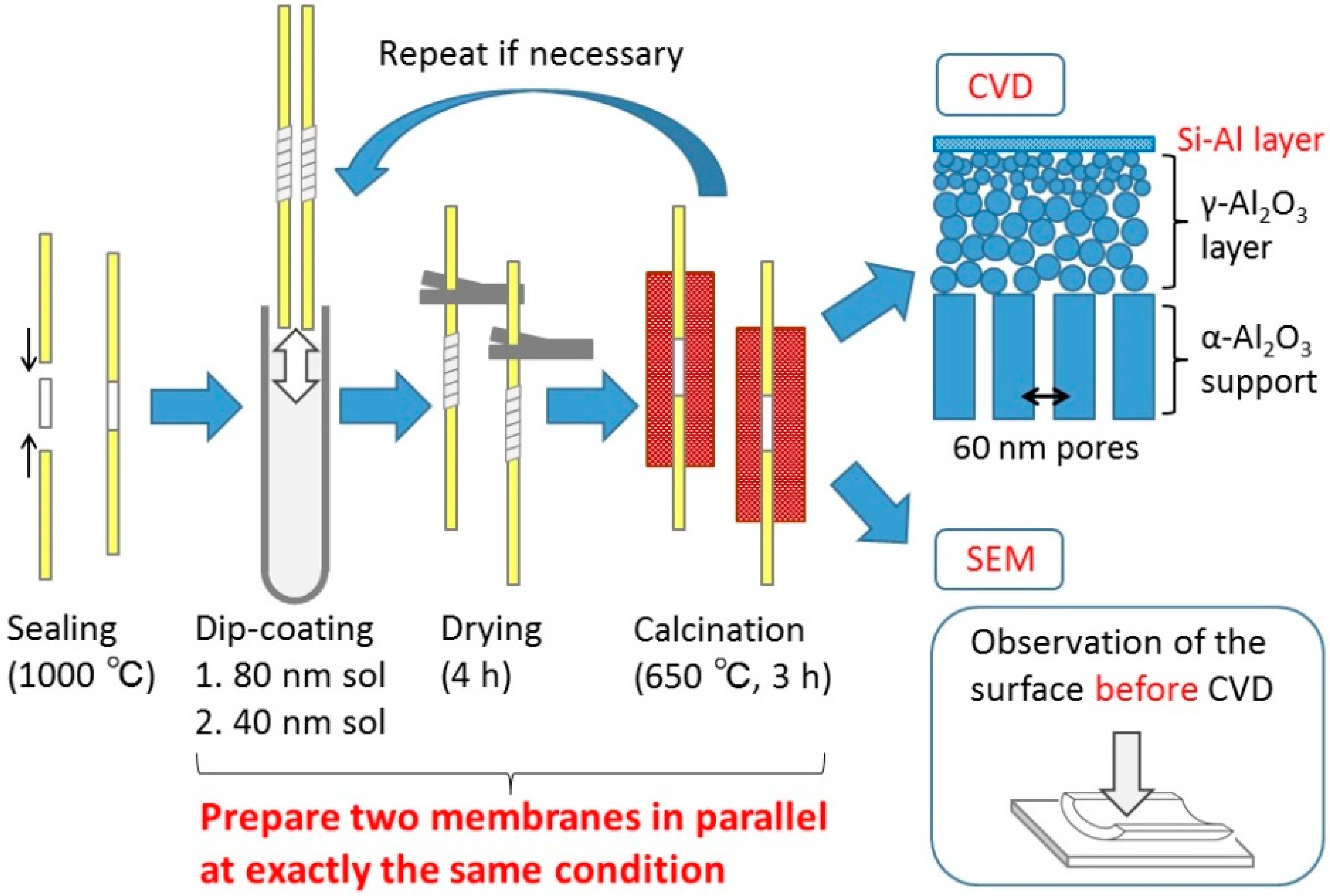
2.2. Membrane Fabrication

2.2.1. Preparation of the Dipping Sols

The γ-alumina layers were prepared by sol-gel coating of boehmite sols, which were synthesized through the hydrolysis of aluminum isopropoxide (Aldrich, >98%) and subsequent peptization by nitric acid, as reported previously [58]. The boehmite particle sizes were controlled by the time of hydrolysis and the amount of nitric acid. The actual dipping solutions were prepared by mixing the boehmite sols with a polyvinyl alcohol (PVA, Polysciences, M.W. = ~78,000) solution to minimize the risk of cracking by slightly raising the sol viscosity. The obtained concentration of the sol and PVA were 0.15 wt.% and 0.35 wt.%, respectively.

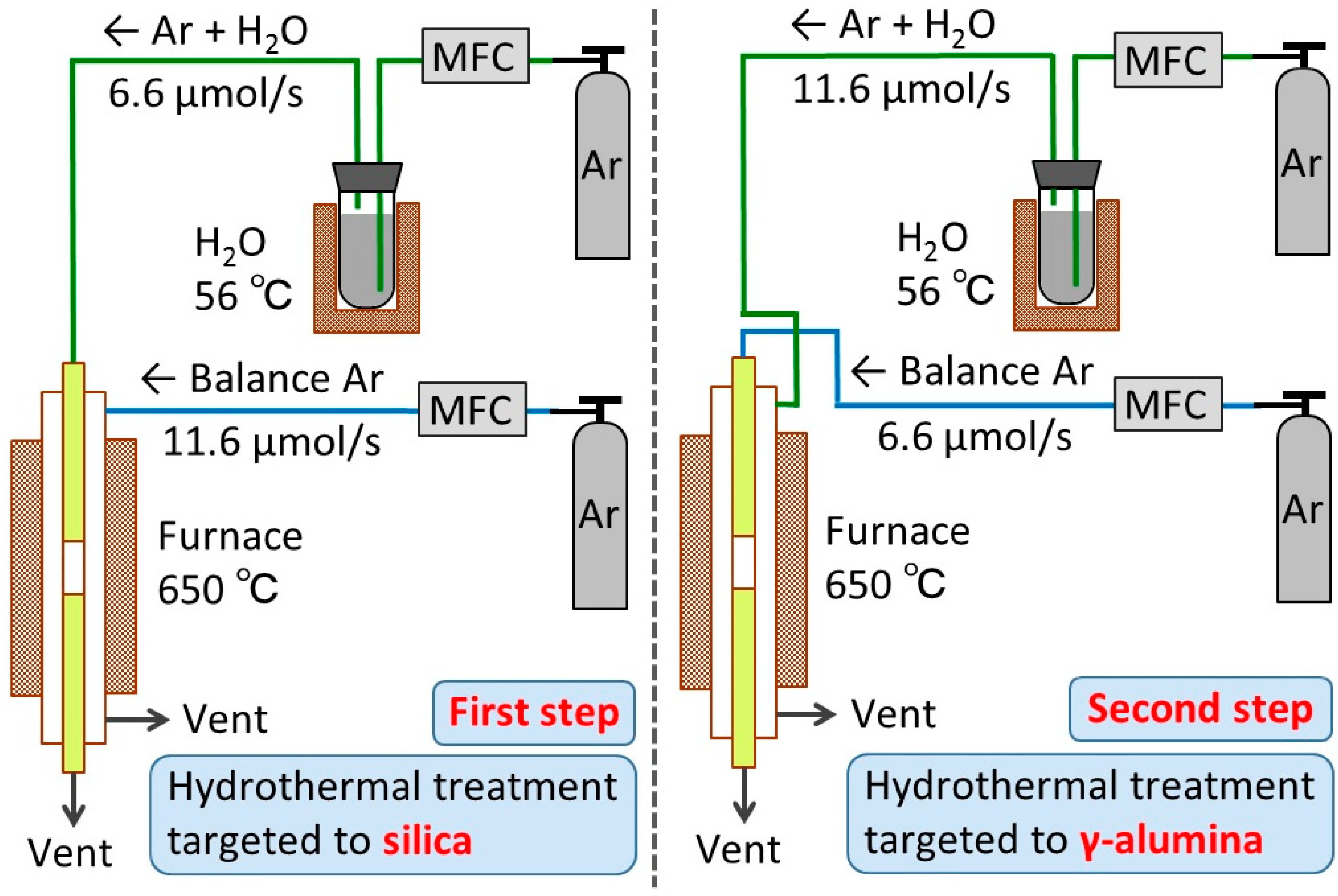
2.2.2. Preparation of the Intermediate Layers

First, a commercial α-alumina tube (i.d. = 4 mm, o.d. = 6 mm, length = 30 mm) with 60 nm pores (Noritake Corporation) was connected to non-porous alumina tubes (i.d. = 4 mm, o.d. = 6 mm, length = 200 mm) at both ends with ceramic joints, which were made by applying a glass paste and firing at 1000 °C. Second, the tube was dipped into the dipping solution for 10 s with its outer surface wrapped with Teflon tape. Third, the tube was dried in a laminar flow enclosure with high efficiency particulate air filters for 4 h, and was calcined at 650 °C for 3 h. Here, a relatively slow heating/cooling rate of 1.5 °C/min was applied in order to minimize the risk of cracking due to different thermal expansion coefficients between the support and the intermediate layer. The dipping-calcining cycle was repeated as necessary.

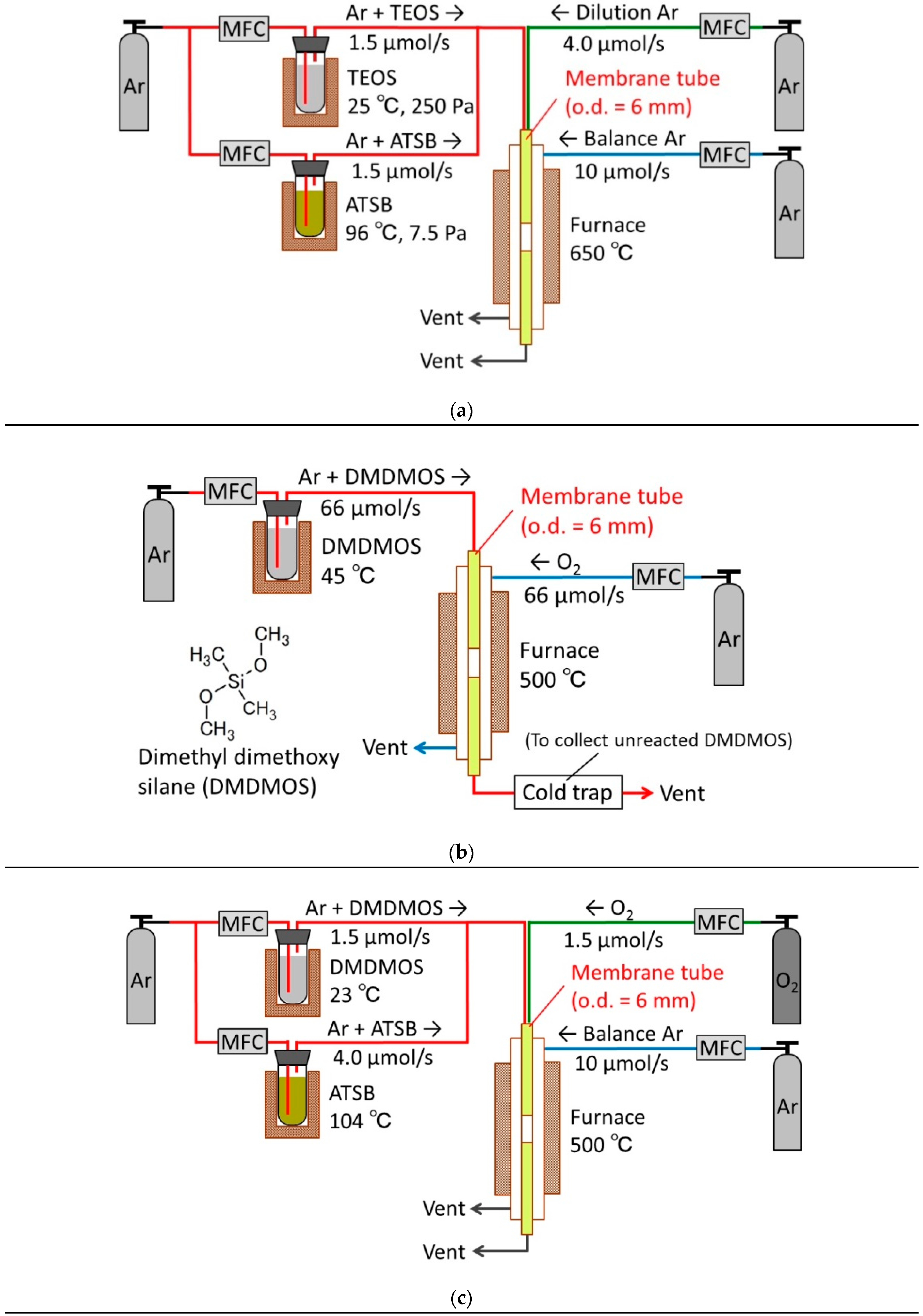
2.2.3. Preparation of the Topmost Silica Layers

The topmost silica layers were synthesized by chemical vapor deposition (CVD), which placed a thin (20~30 nm) silica layer on top of the γ-alumina substrate by the thermal decomposition of the silica precursor compound. First, a conventional silica precursor, tetraethyl orthosilicate (TEOS) (Aldrich, 98%), was used to concentrate on the optimization of the intermediate layer. The schematic diagram of the CVD apparatus is shown in Figure 2a. The 6 mm diameter support tube was coaxially fixed inside the stainless reactor using machined Swagelok fittings with Teflon ferrules. The assembly was placed in an electric furnace and was heated to 650 °C at a heating rate of 1.5 °C/min. The bubbler temperature for the TEOS delivery was kept at 25 °C, which gave a TEOS vapor pressure of 250 Pa (obtained from the following Antoine equation).
log 10 P = A B T + C , A = 4.17312 , B = 1561.277 , C = 67.572 , P [ bar ] , T [ K ]
To improve the hydrothermal stability, a silica-alumina composite membrane was fabricated using a second bubbler to deliver aluminum tri-sec-butoxide (ATSB) as a secondary component in addition to the TEOS (Figure 1a). In this case, the bubbler temperature for the ATSB delivery was set at 96 °C so that the Al/Si ratio would be 0.03. This value was determined by considering the tradeoff between the hydrothermal stability and the H2 selectivity obtained in a previous study [44]. The two carrier gases were premixed with a dilution Ar gas before introduction to the inside of the support tube. The lines leading to the inner tube were heated by a ribbon heater to prevent condensation of the precursor compounds. A balance argon gas was also introduced to the outer shell in order to maintain pressure balance between inside and outside of the support tube and minimize the loss of H2 permeance due to silica deposition within the pores of the γ-alumina. After the CVD process was finished, the assembly was purged with the balance and dilution Ar gases for about 15 min to sweep out any unreacted precursor compounds or reaction byproducts.
To further improve the H2 permeance without compromising the H2 selectivity, a novel silica precursor reported in the literature, dimethyldimethoxysilane (DMDMOS) [17], was also examined. The reported H2 permeance and H2/N2 selectivity were 9.0 × 10⁻⁷ mol m−2 s−1 Pa−1 and 920, respectively, but the authors did not describe any detailed information about the gas permeation mechanism or the long-term stability of the membrane. Therefore, these will be investigated in this study.
To synthesize DMDMOS membranes, both counter-diffusion CVD (Figure 2b) and one-sided diffusion CVD (Figure 2c) were applied, whereas the previous study [17] dealt with only counter-diffusion CVD. Particularly, the one-sided diffusion CVD made it easier to add the stream of ATSB to improve the hydrothermal stability. In both cases, the CVD temperature was set at 500 °C in order to prevent support cracking due to the large reaction heat between DMDMOS and O2 in accordance with the previous report [17].

2.3. Evaluation of the As-Synthesized Membranes
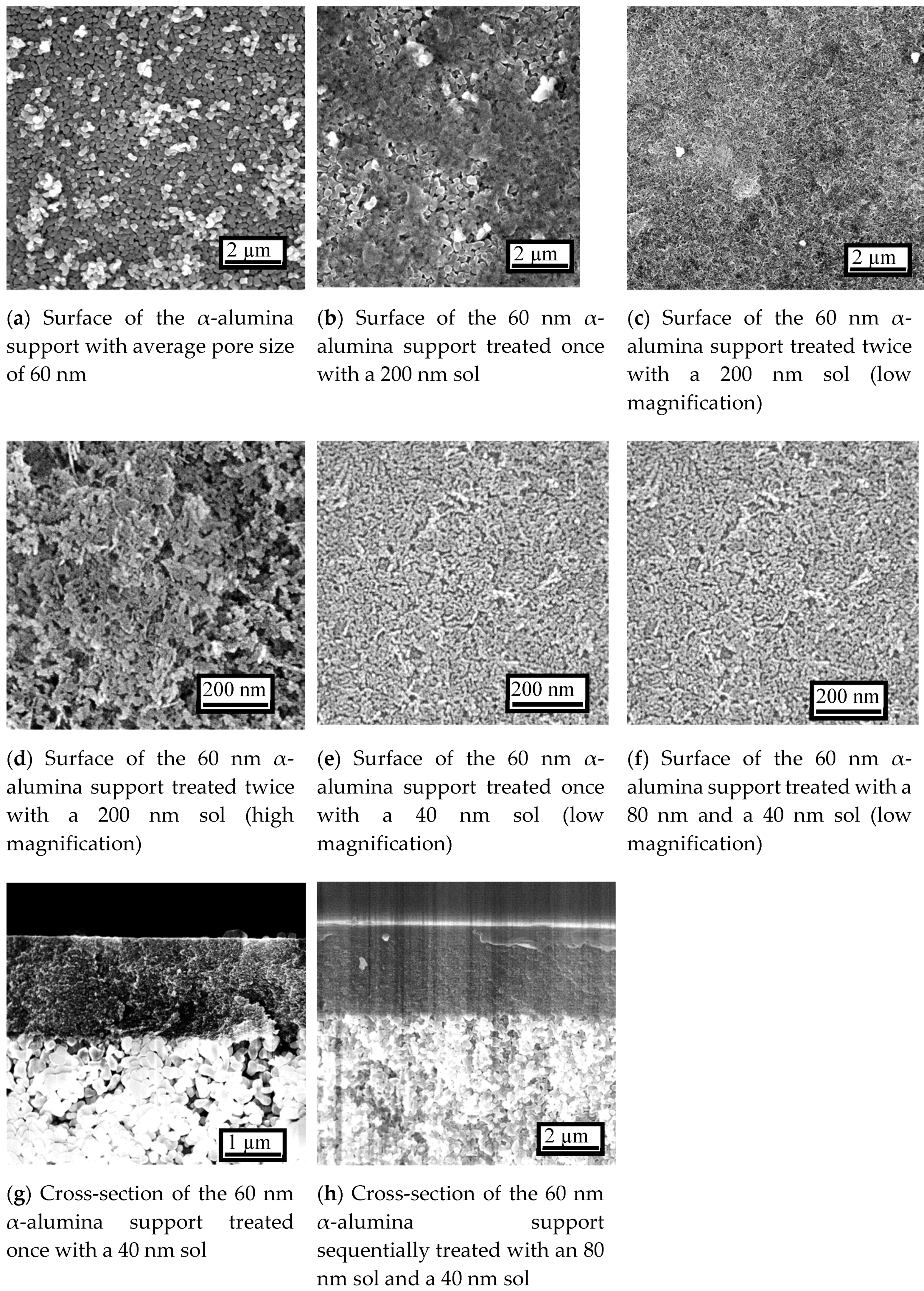
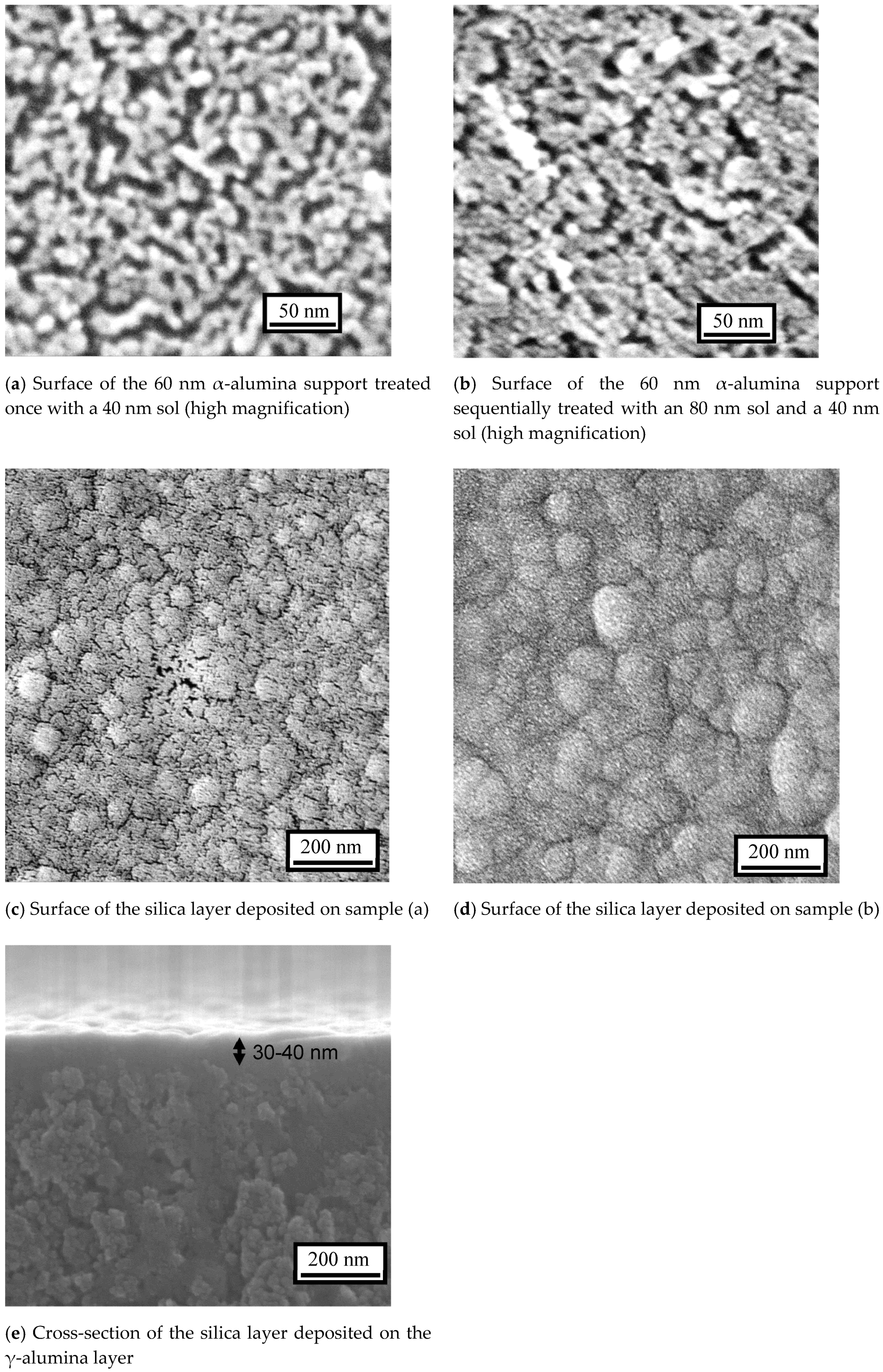
2.3.1. SEM Analysis

The surface and cross-sectional microstructures of the membranes were studied using field emission scanning electron microscopy (FESEM, S-900, Tokyo, Japan). Samples were obtained by mechanically slicing the tubular membranes with a diamond saw and subsequently chopping the sliced discs with a cutter. The samples were sputtered with platinum for 15 s before the measurements with SEM. Through the observation, the following points were examined (Table 1).

2.3.2. Single Gas Permeation Test

The CVD process was interrupted at various deposition times, and gas permeation tests were carried out at 650 °C using the same apparatus. The sample gases (H2, He, Ne, N2, CO2, Ar) were introduced into the inside of the membrane tube, the bottom end of which was closed. Then, the gas permeation rates from the outer shell were measured either by a flow meter or a gas chromatograph. Permeances were calculated using the following equation:
P ¯ = F A Δ p
where P ¯ is the permeance (mol m−2 s−1 Pa−1), F is the molar flow rate (mol s−1), A is the permeation area (m2), and Δ p is the pressure difference across the membrane (Pa). The permeation area, A , was calculated by:
A = π L ( r 1 r 2 ) ln ( r 1 r 2 )
where L is the effective membrane length, r 1 is the outer diameter, and r 2 is the inner diameter. The ideal selectivity was defined as the ratio of the single gas permeances:
α i j = P ¯ i P ¯ j
where α i j is the selectivity of gas i versus j , P ¯ i is the permeance of gas i (mol m−2 s−1 Pa−1), and P ¯ j is the permeance of gas j (mol m−2 s−1 Pa−1). For permeances higher than 10−9 mol m−2 s−1 Pa−1, an electronic mass flow meter was used for the measurement, and for lower permeances, a Shimazu 8A gas chromatograph was employed. In the latter case, He gas at a known flow rate was also introduced to the outer shell in order to sweep the permeated molecules to the detector of the gas chromatograph. Then, the gas flow rate was calculated from the He flow rate and sample gas concentration, which was obtained from the average peak area and the calibration curve. The selectivity was calculated as the ratio of the single gas permeances of H2 to N2, CO2, or Ar.

2.3.3. Hydrothermal Stability Test

As was described in the introduction (Section 1), both the topmost selective layer and its support layer must be substantially stable under the operating conditions; otherwise, it is impossible to use the membrane in practical applications. However, there are limited numbers of publications dealing with hydrothermal stability tests on both sides of the membrane. Therefore, in this study, hydrothermal stability tests targeting both the silica and the γ-alumina layers were conducted at 650 °C, up to 200 h.
First, an Ar flow at 6.6 μmol s−1 (flow rates in μmol s−1 can be converted into ml (NTP) min−1 by multiplying by 1.5) was passed through a heated bubbler containing distilled water and was then introduced to the inside of the membrane tube to directly contact the silica layer. The bubbler temperature was set at 56 °C so that the Ar stream would contain 16 mol% water vapor. At the same time, another Ar flow at 11.6 μmol s−1 was introduced to the outside of the membrane tube. Both sides of the membrane were kept at atmospheric pressure. The hydrothermal treatment was interrupted at several exposure times, and the permeances of H2, He, and N2 were measured to monitor the changes in the membrane performance. To make the permeance measurements, the humidified Ar was changed to a pure Ar for about 20 min to dry the membranes. The wet Ar flow was resumed immediately after the permeance measurements. The cycle was repeated several times until the membrane performance became almost unchanged.
Next, the configuration was altered. An Ar flow at 11.6 μmol s−1 containing 16 mol% water vapor was introduced to the outer shell to directly contact the γ-alumina layer, while another dry Ar stream at 6.6 μmol s−1 was introduced to the inner tube. The gas permeances were measured after several exposure times just like the previous case. Figure 3 summarizes the experimental procedures for the above-described hydrothermal stability tests. As a note, the lines for the delivery of humidified Ar were maintained above 100 °C using ribbon heaters to prevent condensation of water vapor.

3. Results and Discussion

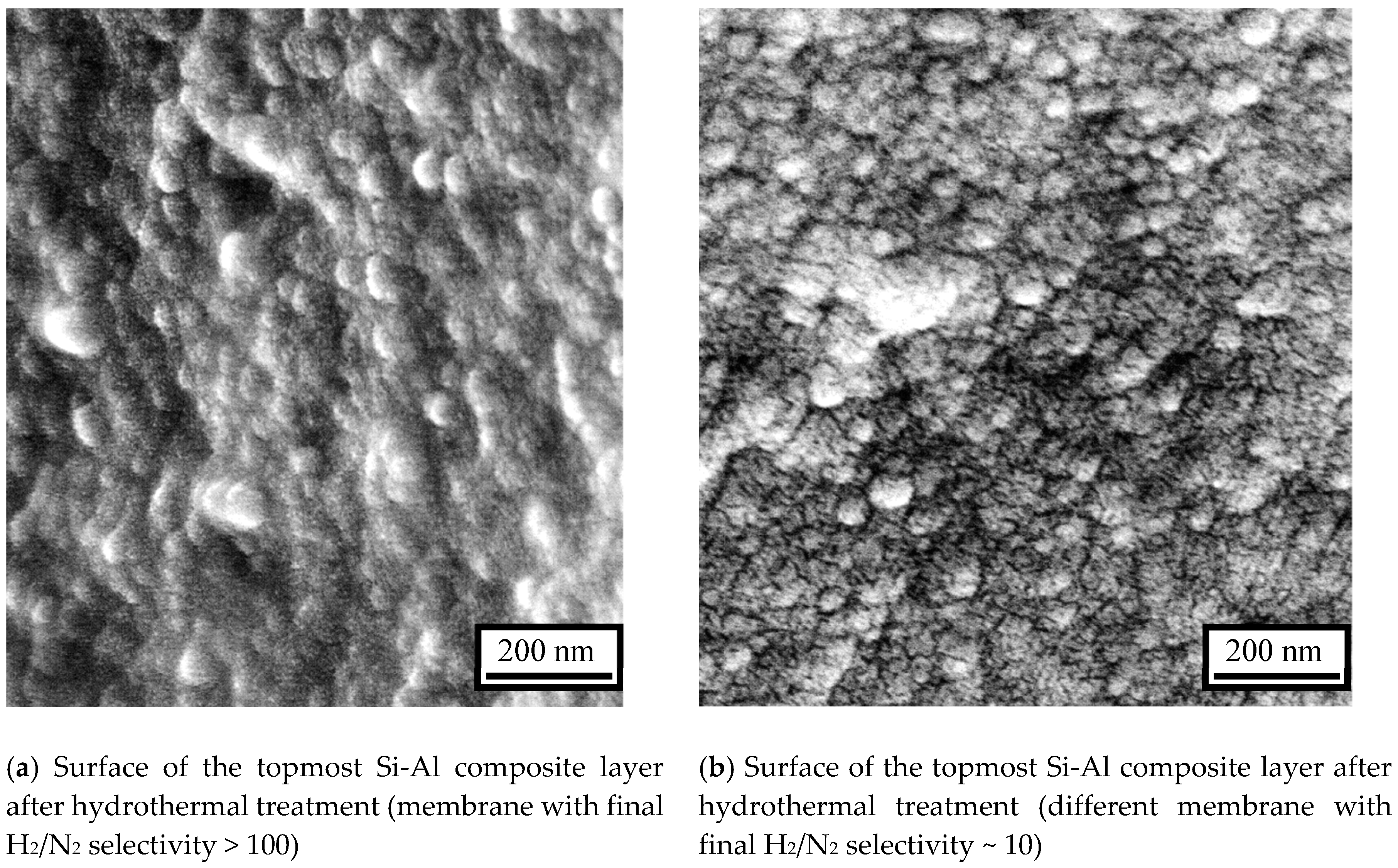
3.1. Morphology and Structure of the Membranes

Studies with scanning electron microscopy (SEM) revealed a progression of structure in the different membranes (Figure 4). The surface image of the α-alumina support with nominal pore size of 60 nm (Figure 4a) treated once with a 200 nm sol shows that although a certain amount of γ-alumina was deposited on the α-alumina, there were large areas of uncovered α-alumina particles (Figure 4b). The image of the α-alumina support treated by a 200 nm sol twice shows that the α-alumina was totally covered by γ-alumina (Figure 4c). These results mean that at least two dipping-calcining cycles are required to eliminate large defects if large sols are used first. In addition, the support had a coarse surface and relatively large pores (>5 nm) (Figure 4d), so additional treatment with a smaller sol was necessary, thus bringing the total number of dipping-calcining cycles to three.
The γ-alumina surface prepared by dip-coating the α-alumina support with a 40 nm sol (Figure 4e) and 80 and 40 nm sols (Figure 4f) shows the successful formation of smooth and uniform γ-alumina layers. In addition, their cross-sectional images show that the thickness of the γ-alumina layer was about 1 μm for the former (Figure 4g) and about 2 μm for the latter (Figure 4h). These results suggest that macro-porous α-alumina can be completely covered by γ-alumina even if the boehmite particle size is smaller than, or similar to, the support pore size. This has not been reported before.
To further investigate the microstructural differences between these two samples, pictures at higher magnification were taken (Figure 5). Careful observation reveals a slightly higher porosity for the sample with one treatment with 40 nm particles (Figure 5a) than that with successive 80 and 40 nm particles (Figure 5b). Then, the particle stacking density is slightly lower for the former. However, it was difficult to confirm a significant difference even with the nearly maximum resolution of SEM. Earlier studies [54,55,56] have demonstrated the usefulness of nanopermporometry in quantitating the pore size distribution of intermediate layers. Unfortunately, this was not undertaken in the present study. However, the microscopy does indicate that when only one intermediate layer was applied, the surface was only partly covered.
Although there were no clear differences between the samples before CVD, significant differences were found for the samples after CVD. For the sample with one layer of 40 nm sol, the formation of a silica layer was not complete and there were many visible pinhole defects (Figure 5c), with those at the center of the picture being especially conspicuous. For the sample with successive layers of 80 and 40 nm sols, the surface was formed from continuous rounded structures, which is characteristic of a CVD-derived silica layer (Figure 5d) [59]. In addition, its cross-sectional image revealed that the thickness of the silica layer was about 30–40 nm (Figure 5e), which was similar to that in the previous study. These results clearly show that a smooth and uniform silica layer was successfully formed, although the dipping-calcining cycle was performed only twice on the macro-porous support. As a summary of all the above findings, at least two dipping-calcining cycles are necessary in order to obtain a pinhole-free membrane.

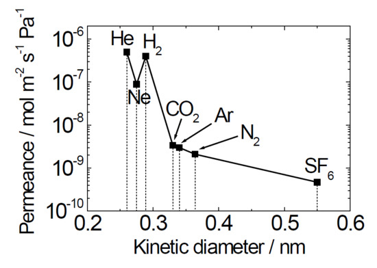
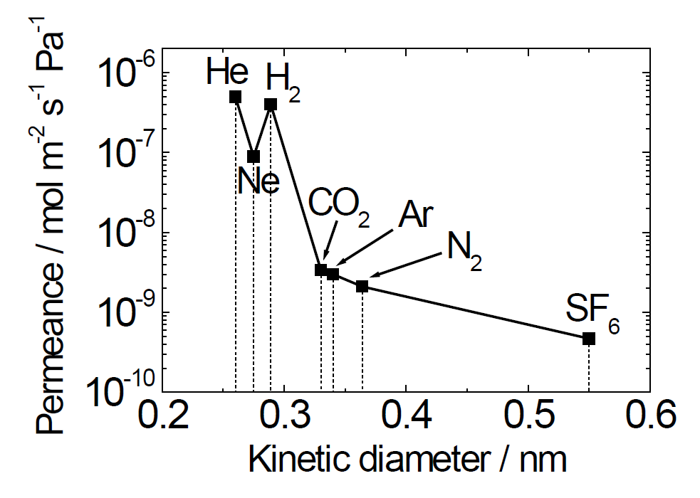
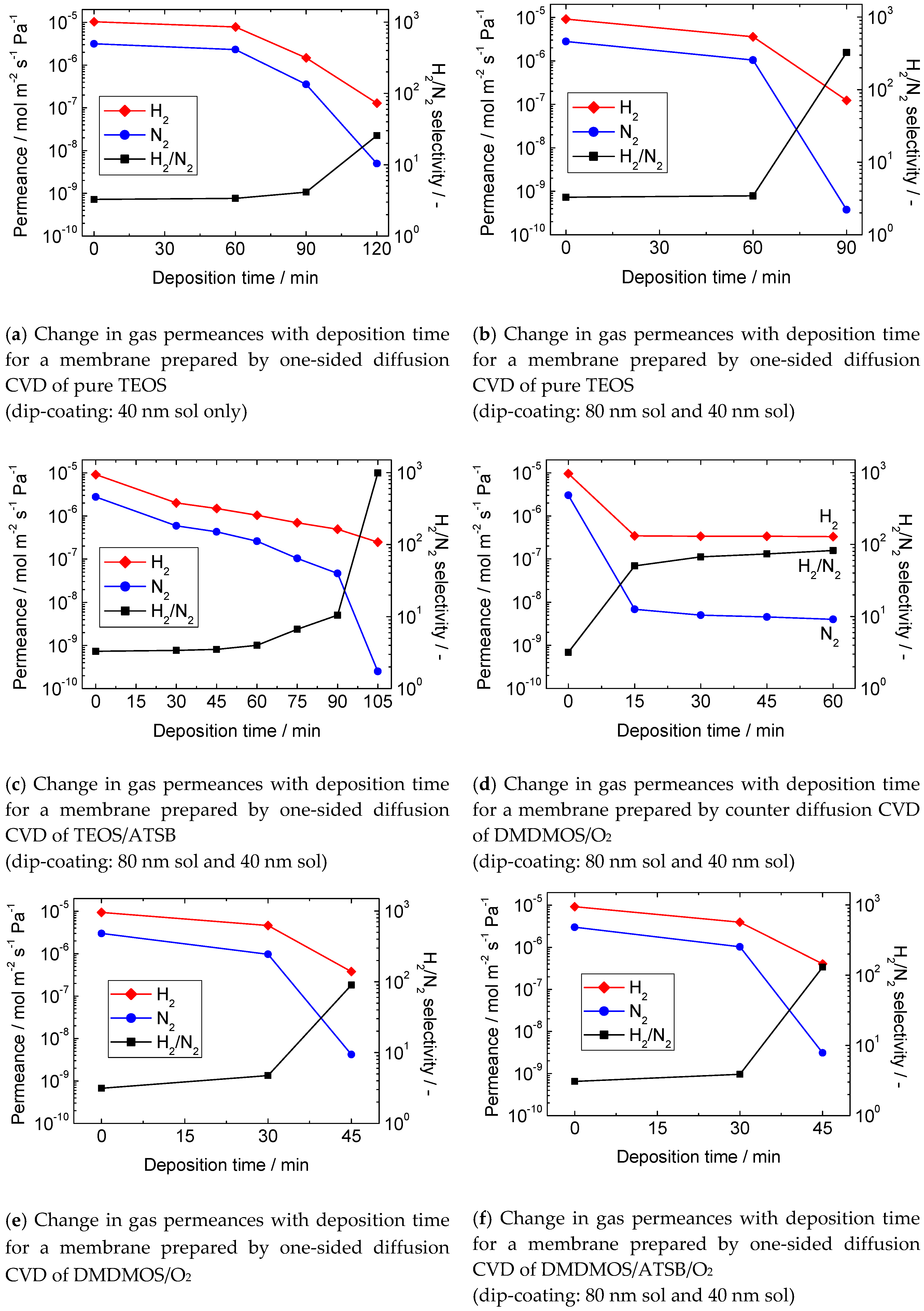
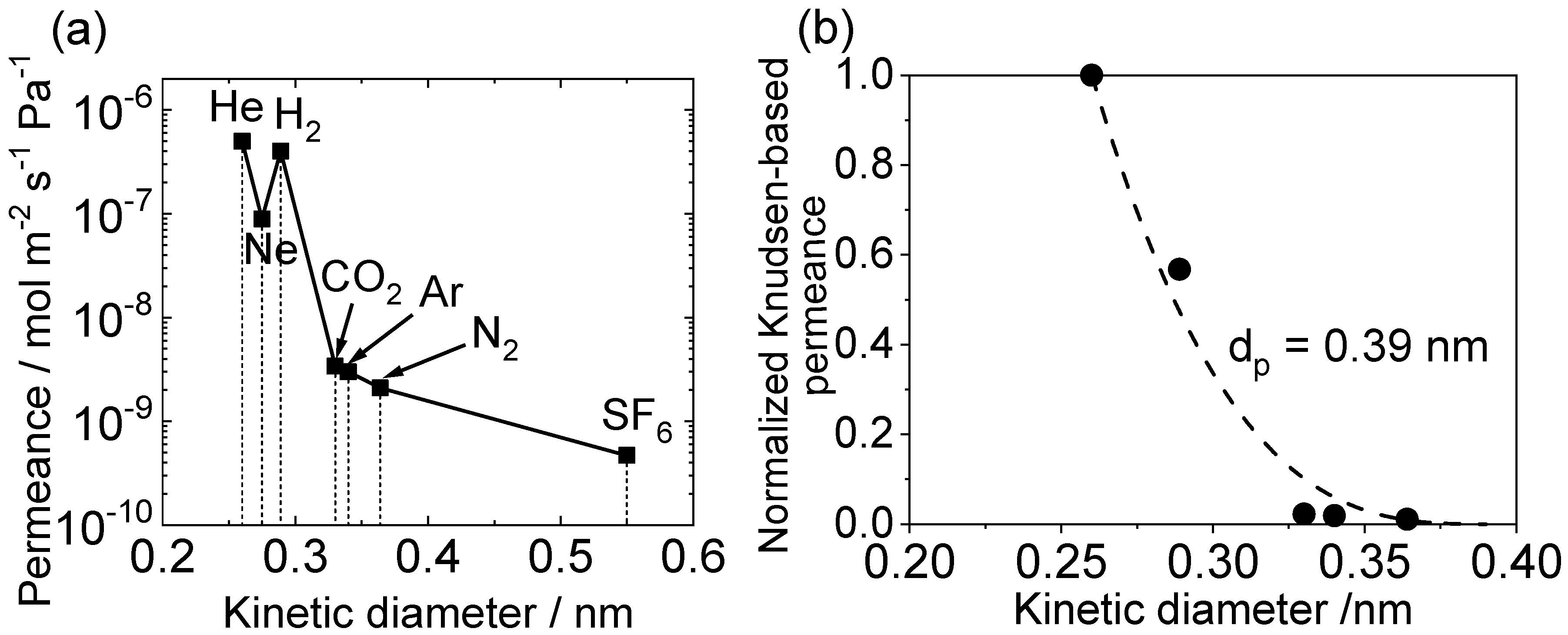
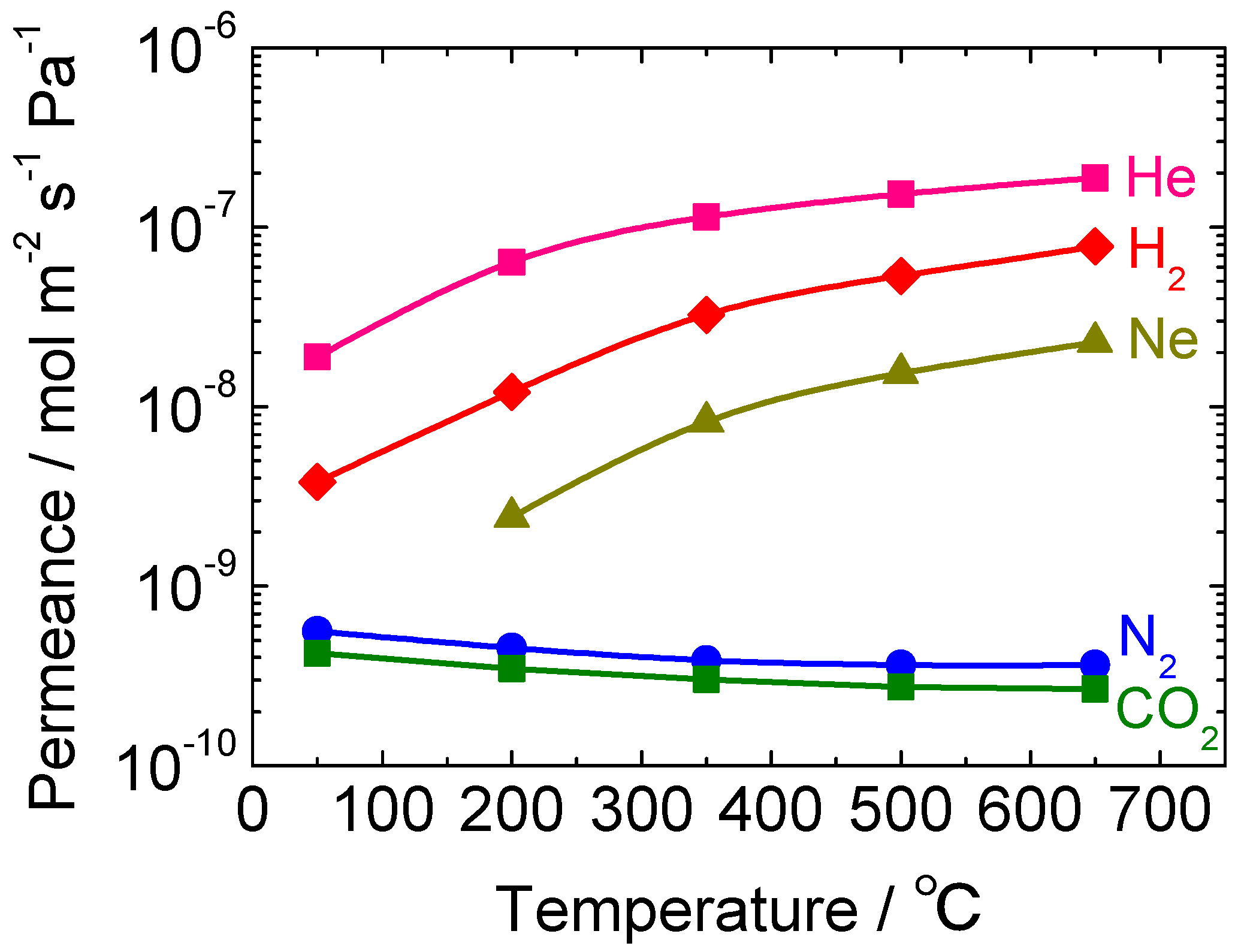
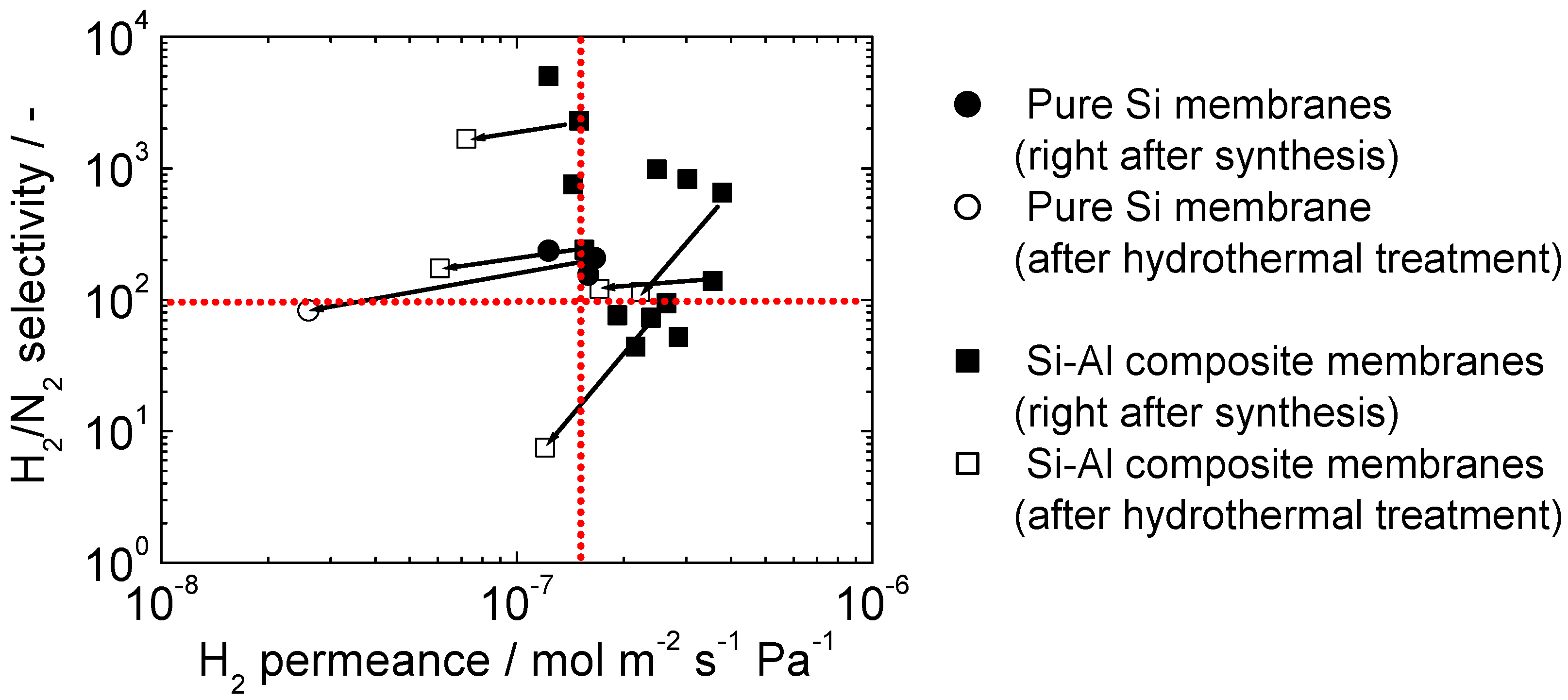
3.2. Gas Permeation Properties of the Membranes

Figure 5 shows the changes in gas permeances during CVD for various types of membranes fabricated in this research. At the beginning of the study, a conventional silica precursor, TEOS, was applied to concentrate on the optimization of the intermediate layer. For the membrane with one treatment with a 40 nm sol, the H2 permeance at 650 °C was 1.2 × 10⁻⁷ mol m−2 s−1 Pa−1 and the H2/N2 selectivity was 26 after 120 min of CVD (Figure 6a). This low selectivity is resonant with the defective surface structure revealed by SEM (Figure 5c). On the other hand, for the membrane successively treated with 80 nm and 40 nm sols, the H2 permeance was the same (1.2 × 10⁻⁷ mol m−2 s−1 Pa−1), but the H2/N2 selectivity was 330 after 90 min of CVD (Figure 6b). This result clearly demonstrated that a defect-free membrane (Figure 5d) can be synthesized with only two dipping-calcining cycles in spite of the use of a macro-porous 60 nm α-alumina support. Previous studies had used supports with substrate pores of 5 nm [28,35,44]. Therefore, the repetition number of the dipping-calcining cycle was fixed at two for the subsequent studies.
Figure 6c shows the results for one of the successfully prepared membranes by the dual-element CVD of TEOS and ATSB. After 105 min of deposition, the H2 permeance and the H2/N2 selectivity at 650 °C were 2.5 × 10⁻⁷ mol m−2 s−1 Pa−1 and 980, respectively. The original purpose of the addition of ATSB was to improve the hydrothermal stability (described later), but the H2 permeance was also improved compared to the TEOS-derived membranes.
To further improve the H2 permeance, the silica precursor was changed from TEOS to DMDMOS. Figure 6d shows the results for the membrane prepared by counter diffusion CVD of DMDMOS and O2. In this case, the membrane fabrication was mostly finished within the first 15 min. After that, the H2 permeance became almost constant, whereas the N2 permeance still decreased slowly, probably because of the modification of some small remaining pores. It is evident that thermal decomposition of DMDMOS was almost negligible, and it actually needed the presence of O2 to form a SiO2 film. After 60 min of CVD, the H2 permeance and the H2/N2 selectivity at 500 °C were 3.3 × 10⁻⁷ mol m−2 s−1 Pa−1 and 82, respectively. Considering the fact that the measurement was taken at 500 °C, the H2 permeance was already much higher than that for a TEOS-derived membrane, but it was not as high as the literature value (9.0 × 10⁻⁷ mol m−2 s−1 Pa−1) [17]. Figure 6e shows the results for the membrane prepared by one-sided diffusion CVD of DMDMOS and O2. After 45 min of CVD, the H2 permeance and the H2/N2 selectivity at 500 °C were 3.8 × 10⁻⁷ mol m−2 s−1 Pa−1 and 90, respectively. Finally, Figure 6f shows the results of the membrane prepared by one-sided diffusion CVD of DMDMOS/ATSB/O2. After 45 min of CVD, the H2 permeance and the H2/N2 selectivity at 500 °C were 4.0 × 10⁻⁷ mol m−2 s−1 Pa−1 and 130, respectively.
Overall, the H2 permeances of the DMDMOS-derived membranes were not as high as that reported in the literature (9.0 × 10⁻⁷ mol m−2 s−1 Pa−1) [17], probably due to the lack of optimization of the CVD parameters. However, the permeance measurements for several gas species (Figure 7a) revealed that the DMDMOS-derived membrane may have a looser silica network compared to the TEOS-derived membranes. The first evidence for this inference is that the He/H2 permeance ratio for the fresh DMDMOS membrane was as low as 1.2. The value was much lower than those for TEOS-derived membranes (usually >2.0), suggesting that the average pore size of the DMDMOS-derived silica network was significantly larger than the kinetic diameters of H2 (0.289 nm) or He (0.26 nm). In fact, the H2 permeance was higher than that for a TEOS-derived membrane, but the He permeance was lower.
The data for the different gases (Figure 7a) can be analyzed by a normalized Knudsen-based permeance method [20]. The method is derived from the gas translation model. First, the gas permeances of the various gases with different kinetic diameters were converted to normalized Knudsen permeances using Equation (5). The obtained results were then plotted as a function of molecular size (Figure 7b). Finally, Equation (6) was used to fit the experimental data, using dp as fitting parameter.
f = P i ¯ P ¯ H e   M H e M i
f = ( 1 d i d p ) 3 ( 1 d H e d p ) 3
In these equations, where f represents the ratio of the permeance of the i-th component ( P i ¯ ) to that predicted from a reference component (He) based on the Knudsen diffusion mechanism, di is the kinetic diameter of gas i (nm), dHe is the kinetic diameter of helium and dp is the estimated membrane pore size (nm). P ¯ H e   M H e M i is the permeance of the i-th component predicted from the He permeance under the Knudsen diffusion mechanism. MHe and Mi are the molecular weight of helium and gas i, respectively (g mol−1). The analysis gives a pore size of 0.39 nm (Figure 7b). A comparable pure SiO2 membrane derived from TEOS gives a pore size of 0.34 nm [53] to 0.37 nm [60], confirming that the structure of the DMDMOS-derived membrane is looser.
The second evidence for the more open structure of the DMDMOS-derived membrane over a pure TEOS-derived membrane is that the permeance order of CO2, Ar, and N2 followed the order of their molecular size rather than their molecular weight. This behavior can hardly be observed for a TEOS-derived membrane, where larger gas molecules permeate through defects in the membrane by the Knudsen mechanism, thereby resulting in a permeance order dominated by their molecular weight. The molecular sieving effect for CO2, Ar, and N2 strongly suggests that there actually were some micropores present which allowed their passage. Furthermore, although the permeances of the above three gas species were on the order of 10−9 mol m−2 s−1 Pa−1, the permeance of SF6 was on the order of 10−10 mol m−2 s−1 Pa−1. This indicated that the membrane had few defects such as pinholes or cracks, and that CO2, Ar, and N2 permeated through the membrane mainly by the molecular sieving mechanism, and the contribution of the Knudsen permeation was not important. Considering the above findings, there would be a chance to further improve the H2 permeance of the DMDMOS membranes by minimizing the membrane thickness through the optimization of the CVD parameters.

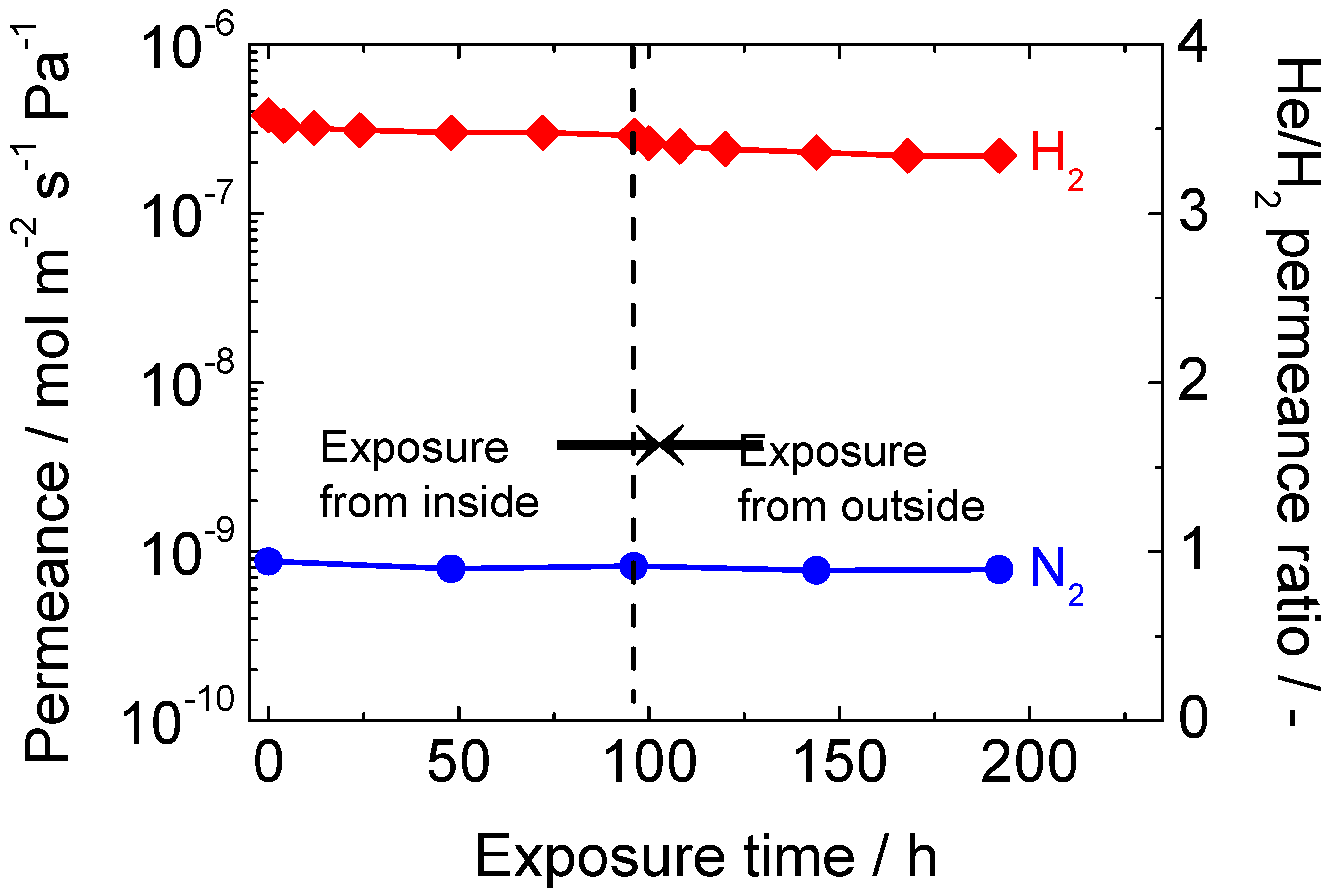
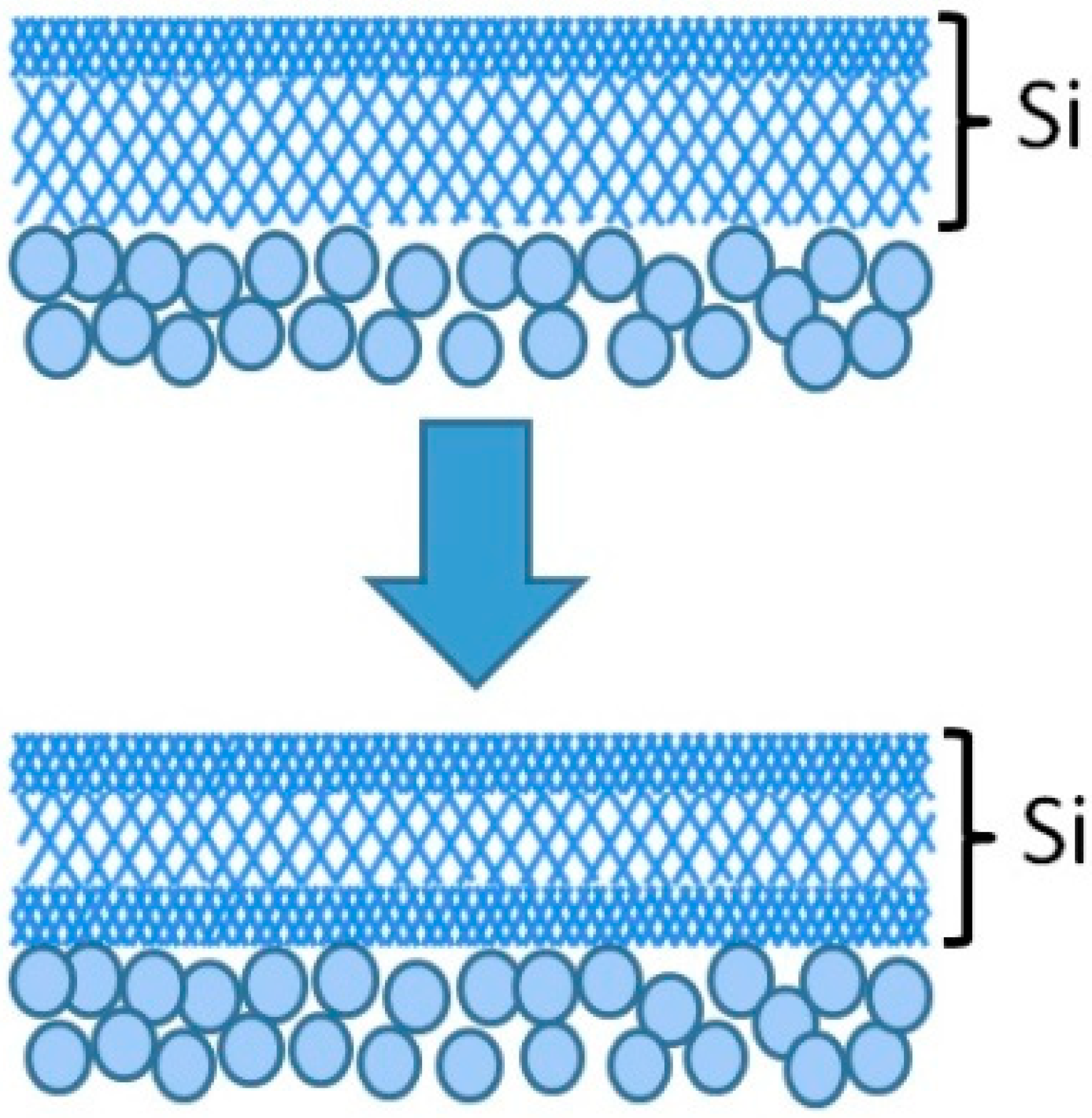
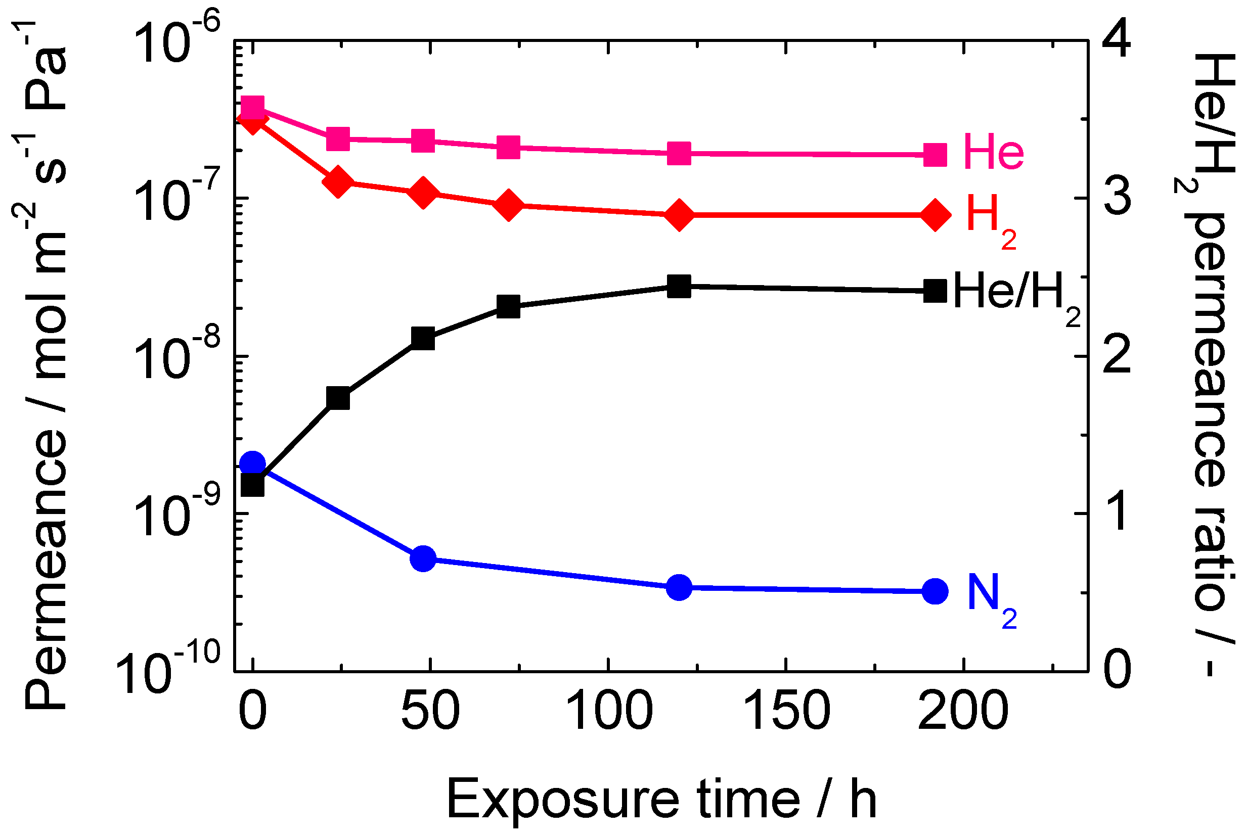
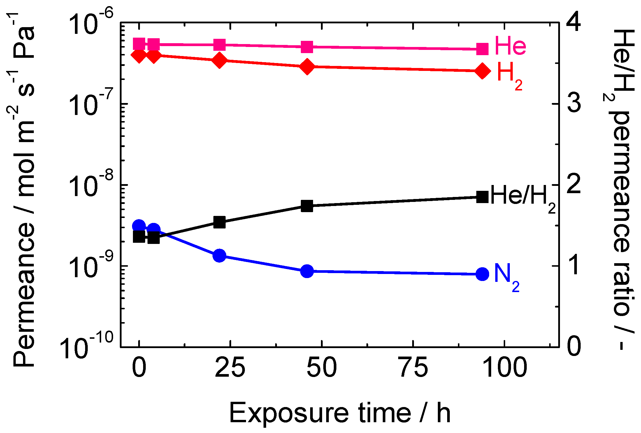
3.3. Hydrothermal Stability of the Membranes

First, a long-term hydrothermal stability test was conducted for both the inside and outside of the membrane tube using a membrane prepared from TEOS and ATSB. The result is shown in Figure 8. When the inner tube was exposed to 16 mol% water vapor, the H2 permeance was rapidly lost for the first 12 h, and then became somewhat stabilized after 96 h of exposure. The tendency was quite normal, and the loss of permeance was much smaller than that for pure silica membranes. The N2 permeance remained almost unchanged. Next, the configuration of the apparatus was altered and the outer shell was exposed to 16 mol% water vapor. The original purpose of this treatment was to examine the degree of pinhole enlargement caused by the deterioration of γ-alumina.
However, unlike the case of membranes prepared by counter-diffusion CVD [41,49], there was no remarkable change in the N2 permeance. This was probably due to the structural difference between the membranes prepared by counter-diffusion CVD and one-sided diffusion CVD. In the former case, the silica film is generally deposited within the pores of γ-alumina, thus the continuity of the silica might be susceptive to the structural change of γ-alumina. In the latter case, a thin silica “layer” is deposited on top of the γ-alumina layer, so pinholes can hardly be created even if the average Kelvin pore diameter of γ-alumina increases by the hydrothermal exposure. Rather than a change of the N2 permeance, a sharp decrease of the H2 permeance was observed again for the first 12 h of exposure. This was probably because of the attack of the H2O molecules on both sides of the silica layer, as shown in Figure 9.
Although the reported kinetic diameter of H2O has some variation in the literature (0.265 nm [32], 0.2995 nm and 0.314 nm [61]), the H2O permeance is expected to be more than two magnitudes lower than the H2 permeance according to the literature [57]. Therefore, it is likely that only the silica network near the surface underwent densification during the first hydrothermal treatment to the inner tube. Then, the silica network near the intersection between the silica and γ-alumina underwent densification during the treatment of the outer shell. Another remarkable finding was that the He/H2 permeance ratio tended to increase by exposure to hydrothermal conditions, which has also been pointed out in the literature [41]. This is also indicative of the densification of the silica layer. The kinetic diameters of He and H2 are 0.26 and 0.289 nm respectively, whereas the pore size of the TEOS-derived membrane right after synthesis is roughly estimated to be 0.3 nm. As the densification proceeds, the pore size and the H2 molecular size will become extremely close to each other, but there still will be a relatively large difference between the pore size and the He molecular size. This is why the reduction in the He permeance was not as sharp as that in the H2 permeance.
Next, a hydrothermal stability test was conducted for a pure silica membrane synthesized from DMDMOS, and the result is shown in Figure 10. It was revealed that, although the DMDMOS-derived membrane had better initial performance than a TEOS-derived membrane, it had extremely poor hydrothermal stability and could not maintain its superior performance over a long period of time. The H2 permeance before the hydrothermal exposure was 3.2 × 10⁻⁷ mol m−2 s−1 Pa−1 at 650 °C, and it was reduced by about 75%, and that after 192 h of exposure was 7.8 × 10⁻⁸ mol m−2 s−1 Pa−1. Another remarkable finding was that the N2 permeance also underwent a very large drop from the order of 10−9 mol m−2 s−1 Pa−1 to 10−10 mol m−2 s−1 Pa−1 by the hydrothermal exposure. This strongly suggests that the micropores through which N2 could permeate had shrunk into much smaller micropores that no longer allowed the permeation of N2.
To obtain a deeper understanding of the gas permeation mechanism of this new membrane, the temperature dependence of the gas permeances after the hydrothermal treatment was investigated and the result is shown in Figure 11. The gas permeation behavior after the densification was quite similar to that for a TEOS-derived membrane, probably because the average pore size of the silica layer became about 0.3 nm or smaller by the hydrothermal exposure. It is remarkable that, although the permeance of CO2 was higher than that of N2 before the exposure, their permeance order became reversed after the exposure, indicating that the permeation mechanism changed from molecular sieve to Knudsen. In any case, a membrane with H2 permeance on the order of 10−8 mol m−2 s−1 Pa−1 is not attractive for membrane reactor applications as a minimum permeance of 10−7 mol m−2 s−1 Pa−1 is needed [40], and therefore, improvement was necessary.
Then, a hydrothermal stability test was conducted for a silica-alumina composite membrane synthesized by the one-sided diffusion CVD of DMDMOS/ATSB/O2, and the result is shown in Figure 12. It can be seen that the hydrothermal stability of the membrane was significantly improved. The initial H2 permeance was 4.0 × 10⁻⁷ mol m−2 s−1 Pa−1, and that after 94 h of exposure became 2.5 × 10⁻⁷ mol m−2 s−1 Pa−1. The reduction was only 38% in this case. This new membrane was used for the membrane reactor studies on the ethane dehydrogenation reaction in a forthcoming study.
In order to make a comparison, surface SEM pictures after the long-term hydrothermal stability tests were taken for both a defect-free membrane and a deteriorated membrane. Figure 13a shows the surface of a membrane which still had H2/N2 selectivity above 100. Although the silica surface shows a granular morphology compared to that of a fresh surface (Figure 5d), the γ-alumina was still completely covered by a continuous silica layer. On the other hand, Figure 13b shows the surface of a different membrane which had H2/N2 selectivity of around only 10 after the hydrothermal exposure. There are many clearly visible pinhole defects, through which larger gas molecules such as N2 or CO2 could permeate by Knudsen diffusion.
Figure 14 shows a summary of the performance of a total number of 16 membranes fabricated in this study, the intermediate layers of which were synthesized by the sequential treatment with an 80 and a 40 nm sol. Even though the synthesis steps were simplified compared to a previous study [35], Si-Al composite membranes with H2 permeance > 1.5 × 10⁻⁷ mol m−2 s−1 Pa−1 and H2/N2 selectivity > 100 have been successfully fabricated many times, demonstrating the level of reproducibility of the membrane fabrication process used in this study. There are many steps that enter into the synthesis, including joining of the support to the dense alumina tubes, the preparation of the sols, the dip-coating procedure, and the CVD process, and it is difficult to control all the steps. Nevertheless, the results are significant as the values of H2 permeance > 1.5 × 10⁻⁷ mol m−2 s−1 Pa−1 and H2/N2 selectivity > 100 noted above were shown to be requirements for a commercial process [36]. This involved the study of the model A → B + C reaction, the dihydrogen-ation of ethane (C2H6 → C2H4 + H2) over a 5 wt% Cr/ZSM-5 catalyst in a conventional packed-bed reactor (PBR) and in a membrane reactor (MR) fitted with hydrogen-selective silica membranes. Specifically, it was demonstrated that for the all-important permeance range of 10−7 and 10−6 mol m−2 s−1 Pa−1, there was an enhancement in yield as H2 selectivity increased from 10 to 20 and 30, but beyond 100, there was little improvement even with a selectivity of 1000 [36]. Thus, a selectivity of 100 is sufficient for most applications involving membrane reactors.
It should be noted, however, that the membrane performance (especially the H2 permeance) tended to be reduced after the long-term hydrothermal treatment, and it was not easy to maintain the above-mentioned performance over a long period of time. It was also remarkable that, when the initial H2/N2 selectivity was lower than 100, the membrane performance tended to deteriorate by the hydrothermal treatment, probably because of fatal pinhole enlargement. This provides a direction for improvement, that is the number of defects should be reduced at the outset.

4. Conclusions

Silica-alumina composite membranes with H2 permeance > 1.5 × 10⁻⁷ mol m−2 s−1 Pa−1 and H2/N2 selectivity > 100 have been successfully fabricated repeatedly, even though the membrane fabrication steps were simplified compared to previous studies. In addition, the use of a novel silica precursor, dimethyl dimethoxy silane (DMDMOS), further improved the H2 permeance without compromising the H2 selectivity. Even though the pure silica membranes synthesized from DMDMOS had poor hydrothermal stability just like the TEOS-derived membranes, the addition of aluminum tri-sec-butoxide (ATSB) rendered the membrane much more stable.

Author Contributions

H.A. carried out the research and wrote the initial draft, A.T. and R.K. helped to direct the research and analyze the results, T.S. helped with the scanning electron microscopy, S.T.O. planned the work, obtained the funding, and edited the manuscript. All authors have read and agreed to the published version of the manuscript.

Funding

This work was supported by the Japan Science and Technology Agency under the CREST program, Grant Number JPMJCR16P2.

Conflicts of Interest

The authors declare no conflict of interest.

References

  1. Gallucci, F.; Fernandez, E.; Corengia, P.; van Sint Annaland, M. Review Recent advances on membranes and membrane reactors for hydrogen production. Chem. Eng. Sci. 2013, 92, 40–66. [Google Scholar] [CrossRef]
  2. Khatib, S.J.; Oyama, S.T. Review of silica membranes for hydrogen separation prepared by CVD. Sep. Purif. Technol. 2013, 111, 20–42. [Google Scholar] [CrossRef]
  3. Khatib, S.J.; Oyama, S.T.; de Souza, K.R.; Noronha, F.B. Review of silica membranes for hydrogen separation prepared by chemical vapor deposition. In Inorganic, Polymeric and Composite Membranes, Structure, Function and Correlations, Membrane Science and Technology Series; Oyama, S.T., Stagg-Williams, S.M., Eds.; Elsevier Science: Amsterdam, The Netherlands, 2011; Volume 14, p. 25. [Google Scholar]
  4. Ten Hove, M.; Luiten-Olieman, M.W.J.; Huiskes, C.; Nijmeijer, A.; Winnubst, L. Hydrothermal stability of silica, hybrid silica and Zr-doped hybrid silica membranes. Sep. Purif. Technol. 2017, 189, 48–53. [Google Scholar] [CrossRef]
  5. Akamatsu, K.; Tago, T.; Seshimo, M.; Nakao, S.-I. Long-term stable H2 production from methylcyclohexane using a membrane reactor with a dimethoxydiphenylsilane-derived silica membrane prepared via chemical vapor deposition. Ind. Eng. Chem. Res. 2015, 54, 3996–4000. [Google Scholar] [CrossRef]
  6. Nagasawa, H.; Minamizawa, T.; Kanezashi, M.; Yoshioka, T.; Tsuru, T. Microporous organosilica membranes for gas separation prepared via PECVD using different O/Si ratio precursors. J. Membr. Sci. 2015, 489, 11–19. [Google Scholar] [CrossRef] [Green Version]
  7. Gao, X.; Diniz da Costa, J.C.; Bhatia, S.K. Adsorption and transport of gases in a supported microporous silica membrane. J. Membr. Sci. 2015, 460, 46–61. [Google Scholar] [CrossRef]
  8. Yin, Y.; Xua, T.; Shen, X.; Wu, H.; Jiang, Z. Fabrication of chitosan/zwitterion functionalized titania–silica hybrid membranes with improved proton conductivity. J. Membr. Sci. 2014, 469, 355–363. [Google Scholar] [CrossRef]
  9. Okubo, T.; Inoue, H. Introduction of specific gas reactivity to porous glass membranes by treatment with tetraethoxysilane. J. Membr. Sci. 1989, 42, 109–119. [Google Scholar] [CrossRef]
  10. Gavalas, G.R.; Megiris, C.E.; Nam, S.W. Deposition of H2-permselective SiO2 films. Chem. Eng. Sci. 1989, 44, 1829–1839. [Google Scholar] [CrossRef]
  11. De Lange, R.S.A.; Keizer, K.; Burggraaf, A.J. Analysis and theory of gas transport in microporous sol-gel derived ceramic membranes. J. Membr. Sci. 1995, 104, 81–91. [Google Scholar] [CrossRef] [Green Version]
  12. Okubo, T.; Haruta, K.; Kusakabe, K.; Morooka, S.; Anzai, H.; Akiyama, S. Preparation of sol-gel derived thin membrane on a porous ceramic hollow filter by the filtration technique. J. Membr. Sci. 1991, 59, 73–83. [Google Scholar] [CrossRef]
  13. Nam, S.W.; Ha, H.Y.; Yoon, S.P.; Han, J.; Lim, T.H.; Oh, I.H.; Hong, S.A. Hydrogen-permselective TiO2/SiO2 membranes formed by chemical vapor deposition. Korean Membr. J. 2001, 3, 69–78. [Google Scholar]
  14. Megiris, C.E.; Glezer, J.H.E. Permeation of silicon dioxide films by low-pressure chemical vapor deposition on dense and porous alumina substrates. Chem. Eng. Sci. 1992, 47, 3925–3933. [Google Scholar] [CrossRef]
  15. Ngamou, P.; Overbeek, J.; Kreiter, R.; van Veen, H.; Vente, J.; Wienk, I.; Cuperus, P.; Creatore, M. Plasma deposited hybrid silica membranes with a controlled retention of organic bridges. J. Mater. Chem. A 2013, 1, 5567–5576. [Google Scholar] [CrossRef] [Green Version]
  16. Walkiewicz-Pietrzykowska, A.; Cotrino, J.; Gonzalez-Elipe, A.R. Deposition of thin films of SiOxCyH in a surfatron microwave plasma reactor with hexamethyldisiloxane as precursor. Chem. Vap. Depos. 2005, 11, 317–323. [Google Scholar] [CrossRef]
  17. Nomura, M. Stability of H2-permselective SiO2 films formed by chemical vapor deposition. Membrane 2007, 32, 340–346. [Google Scholar] [CrossRef] [Green Version]
  18. Zhang, X.; Yamada, H.; Saito, T.; Kai, T.; Murakami, K.; Nakashima, M.; Ohshita, J.; Akamatsu, K.; Nakao, S. Development of hydrogen-selective triphenylmethoxysilane-derived silica membranes with tailored pore size by chemical vapor deposition. J. Membr. Sci. 2016, 499, 28–35. [Google Scholar] [CrossRef] [Green Version]
  19. Niimi, T.; Nagasawa, H.; Kanezashi, M.; Yoshioka, T.; Ito, K.; Tsuru, T. Preparation of BTESE-derived organosilica membranes for catalytic membrane reactors of methylcyclohexane dehydrogenation. J. Membr. Sci. 2014, 455, 375–383. [Google Scholar] [CrossRef]
  20. Lee, H.R.; Kanezashi, M.; Shimomura, Y.; Yoshioka, T.; Tsuru, T. Evaluation and fabrication of pore-size-tuned silica membranes with tetraethoxydimethyl disiloxane for gas separation. AIChE J. 2011, 57, 2755–2765. [Google Scholar] [CrossRef]
  21. Yamaguchi, T.; Ying, X.; Tokimasa, Y.; Nair, B.N.; Sugawara, T.; Nakao, S.I. Reaction control of tetraethylorthosilicate (TEOS)/O3 and tetramethylorthosilicate (TMOS)/O3 counter diffusuin chemical vapour deposition for preparation of molecular-sieve membranes. Phys. Chem. Chem. Phys. 2000, 2, 4465–4475. [Google Scholar] [CrossRef]
  22. Kageyama, N.; Sugawara, T.; Takagaki, A.; Kikuchi, R.; Oyama, S.T. Overcoming pressure drop losses in membrane reactors by semi-batch operation. Sep. Purif. Tech. 2017, 185, 175–185. [Google Scholar] [CrossRef]
  23. Hekkink, J.H.A.; de Lange, R.S.A.; Ten Hoeve, A.A.; Blankenvoorde, P.J.A.M.; Keizer, K.; Burggraaf, A.J. Characterization and permeation properties of binary SiO2-TiO2 and SiO2-Al2O3 modified gamma-alumina membranes. Key Eng. Mater. 1991, 61, 375–378. [Google Scholar]
  24. Yoshida, K.; Hirano, Y.; Fujii, H.; Tsuru, T.; Asaeda, M. Hydrothermal stability and performance of silica-zirconia membranes for hydrogen separation in hydrothermal conditions. J. Chem. Eng. Jpn. 2001, 34, 523–531. [Google Scholar] [CrossRef] [Green Version]
  25. Kanezashi, M.; Yada, K.; Yoshioka, T.; Tsuru, T. Organic-inorganic hybrid silica membranes with controlled silica network size: Preparation and gas permeation characteristics. J. Membr. Sci. 2010, 348, 310–318. [Google Scholar] [CrossRef]
  26. Li, H.; Schygulla, U.; Hoffmann, J.; Nichoff, P.; Haas-Santo, K.; Dittmeyer, R. Experimental and modeling study of gas transport through composite ceramic membranes. Chem. Eng. Sci. 2014, 108, 94–102. [Google Scholar] [CrossRef]
  27. Oyama, S.T.; Lee, D.; Hacarlioglu, P.; Saraf, R.F. Theory of hydrogen permeability in nonporous silica membranes. J. Membr. Sci. 2004, 244, 45–53. [Google Scholar] [CrossRef]
  28. Gu, Y.; Oyama, S.T. Ultrathin, hydrogen-selective silica membranes deposited on alumina-graded structures prepared from size-controlled boehmite sols. J. Membr. Sci. 2007, 306, 216–227. [Google Scholar] [CrossRef]
  29. Mise, Y.; Ahn, S.-J.; Takagaki, A.; Kikuchi, R.; Oyama, S.T. Fabrication and evaluation of trimethylmethoxysilane (TMMOS)-derived membranes for gas separation. Membranes 2019, 9, 123. [Google Scholar] [CrossRef] [Green Version]
  30. Kato, H.; Lundin, S.-T.B.; Ahn, S.-J.; Takagaki, A.; Kikuchi, R.; Oyama, S.T. Gas separation silica membranes prepared by chemical vapor deposition of methyl-substituted silanes. Membranes 2019, 9, 144. [Google Scholar] [CrossRef] [Green Version]
  31. Oyama, S.T.; Yamada, M.; Sugawara, T.; Takagaki, A.; Kikuchi, R. Review on mechanisms of gas permeation through inorganic membranes. J. Jpn. Pet. Inst. 2011, 54, 298–309. [Google Scholar] [CrossRef]
  32. Igi, R.; Kanezashi, M.; Yoshioka, T.; Fujisaki, S.; Iwamoto, Y.; Tsuru, T. Permeation properties of hydrogen and water vapor through porous silica membranes at high temperatures. AIChE J. 2011, 57, 618–629. [Google Scholar]
  33. Kanezashi, M.; Sasaki, T.; Tawarayama, H.; Nagasawa, H.; Yoshioka, T.; Ito, K.; Tsuru, T. Experimental and theoretical study on small gas permeation properties through amorphous silica membranes fabricated at different temperatures. J. Phys. Chem. 2014, 118, 20323–20331. [Google Scholar] [CrossRef]
  34. Okubo, T.; Watanabe, M.; Kusakabe, K.; Morooka, S. Preparation of γ-alumina thin membrane by sol-gel processing and its characterization by gas permeation. J. Mater. Sci. 1990, 25, 4822–4827. [Google Scholar] [CrossRef]
  35. Gu, Y.; Oyama, S.T. High molecular permeance in a poreless ceramic membrane. Adv. Mater. 2007, 19, 1636–1640. [Google Scholar] [CrossRef]
  36. Ahn, S.J.; Yun, G.N.; Takagaki, A.; Kikuchi, R.; Oyama, S.T. Effects of pressure contact time, permeance, and selectivity in membrane reactors: The case of the dehydrogenation of ethane. Sep. Purif. Technol. 2018, 194, 197–206. [Google Scholar] [CrossRef]
  37. Ma, L.-C.; Castro-Dominguez, B.; Kazantzis, N.K.; Ma, Y.H. A cost assessment study for a large-scale water gas shift catalytic membrane reactor module in the presence of uncertainty. Sep. Purif. Technol. 2016, 166, 205–212. [Google Scholar] [CrossRef] [Green Version]
  38. Meng, L.; Yu, X.; Niimi, T.; Nagasawa, H.; Kanezashi, M.; Yoshioka, T.; Tsuru, T. Methylcyclohexane dehydrogenation for hydrogen production via a bimodal catalytic membrane reactor. AIChE J. 2015, 61, 1628–1638. [Google Scholar] [CrossRef]
  39. Araki, S.; Miyanishi, H.; Yano, H.; Tanaka, S.; Miyake, Y. Water gas shift reaction in a membrane reactor using a high hydrogen permselective silica membrane. Sep. Sci. Technol. 2013, 48, 76–83. [Google Scholar] [CrossRef]
  40. Lim, H.; Gu, Y.; Oyama, S.T. Studies of the effect of pressure and hydrogen permeance on the ethanol steam reforming reaction with palladium- and silica-based membranes. J. Membr. Sci. 2012, 396, 119–127. [Google Scholar] [CrossRef]
  41. Nagano, T.; Sato, K. Degradation mechanism of an H2-permselective amorphous silica membrane. J. Mater. Sci. 2014, 49, 4115–5120. [Google Scholar] [CrossRef]
  42. Nomura, M.; Aida, H.; Gopalakrishnan, S.; Sugawara, T.; Nakao, S.I.; Yamazaki, S.; Inada, T.; Iwamoto, Y. Steam stability of a silica membrane prepared by counter diffusion chemical vapor deposition. Desalination 2006, 193, 1–7. [Google Scholar] [CrossRef]
  43. Lim, H.; Gu, Y.; Oyama, S.T. Reaction of primary and secondary products in a membrane reactor: Studies of ethanol steam reforming with a silica-alumina composite membrane. J. Membr. Sci. 2010, 351, 149–159. [Google Scholar] [CrossRef]
  44. Kageyama, N.; Takagaki, A.; Sugawara, T.; Kikuchi, R.; Oyama, S.T. Synthesis and characterization of a silica-alumina composite membrane and its application in a membrane reactor. Sep. Purif. Technol. 2018, 195, 437–445. [Google Scholar] [CrossRef]
  45. Gu, Y.; Hacarlioglu, P.; Oyama, S.T. Hydrothermally stable silica–alumina composite membranes for hydrogen separation. J. Membr. Sci. 2008, 310, 28–37. [Google Scholar] [CrossRef]
  46. Gu, Y.; Oyama, S.T. Permeation properties and hydrothermal stability of silica-titania membranes supported on porous alumina substrates. J. Membr. Sci. 2009, 345, 267–275. [Google Scholar] [CrossRef]
  47. Sea, B.K.; Soewito, E.; Watanabe, M.; Kusakabe, K.; Morooka, S.; Kim, S.S. Hydrogen recovery from a H2–H2O–HBr mixture utilizing silica-based membranes at elevated temperatures. 1. Preparation of H2O- and H2-selective membranes. Ind. End. Chem. Res. 1998, 37, 2502–2508. [Google Scholar] [CrossRef]
  48. Akamatsu, K.; Nakane, M.; Sugawara, T.; Nakao, S.I. Performance under thermal and hydrothermal condition of amorphous silica membrane prepared by chemical vapor deposition. AIChE J. 2009, 55, 2197–2203. [Google Scholar] [CrossRef]
  49. Nagano, T.; Sato, K.; Saito, T.; Takahashi, S. Hydrothermal stability of mesoporous Ni-doped γ-Al2O3. J. Ceram. Soc. Jpn. 2009, 117, 832–835. [Google Scholar] [CrossRef] [Green Version]
  50. Ohta, Y.; Akamatsu, K.; Sugawara, T.; Miyoshi, A.; Nakao, S. Development of pore-size-controlled silica membranes for gas separation by chemical vapor deposition. J. Membr. Sci. 2008, 315, 93–99. [Google Scholar] [CrossRef]
  51. Seshimo, M.; Saito, T.; Akamatsu, K.; Segawa, A.; Nakao, S. Influence of toluene vapor on the H2-selective performance of dimethoxy diphenylsilane-derived silica membranes prepared by the chemical vapor deposition method. J. Membr. Sci. 2012, 415–416, 51–56. [Google Scholar] [CrossRef]
  52. Seshimo, M.; Akamatsu, K.; Furuta, S.; Nakao, S. H2 purification durability of dimethoxy diphenylsilane-derived silica membranes with H2-toluene mixtures. Ind. Eng. Chem. Res. 2013, 52, 17257–17262. [Google Scholar] [CrossRef]
  53. Ahn, S.-J.; Yun, G.-N.; Takagaki, A.; Kikuchi, R.; Oyama, S.T. Synthesis and characterization of hydrogen selective silica membrane prepared by chemical vapor deposition of vinyltriethoxysilane. J. Membr. Sci. 2018, 550, 1–8. [Google Scholar] [CrossRef]
  54. Nishida, R.; Tago, T.; Saitoh, T.; Seshimo, M.; Nakao, S.-I. Development of CVD silica membranes having high hydrogen permeance and steam durability and a membrane reactor for a water gas shift reaction. Membranes 2019, 9, 140. [Google Scholar] [CrossRef] [PubMed] [Green Version]
  55. Sawamura, K.-I.; Okamoto, S.; Todokoro, Y. Development of mass production technology of highly permeable nano-porous supports for silica-based separation membranes. Membranes 2019, 9, 103. [Google Scholar] [CrossRef] [PubMed] [Green Version]
  56. Ishii, K.; Ikeda, A.; Takeuchi, T.; Yoshiura, J.; Nomura, M. Silica-based RO membranes for separation of acidic solution. Membranes 2019, 9, 94. [Google Scholar] [CrossRef] [PubMed] [Green Version]
  57. Nomura, M.; Nishi, Y.; Sakanishi, T.; Utsumi, K.; Nakamura, R. Preparation of thin LiSiO membranes by using a CVD method. Energy Procedia 2013, 37, 1012–1019. [Google Scholar] [CrossRef] [Green Version]
  58. Oyama, S.T.; Hacarlioglu, P. The boundary between simple and complex descriptions of membrane reactors: The transition between 1-D and 2-D analysis. J. Membr. Sci 2009, 337, 188–199. [Google Scholar] [CrossRef]
  59. Oyama, S.T.; Lee, D.; Sugiyama, S.; Fukui, K.; Iwasawa, Y. Characterization of a highly selective hydrogen permeable silica membrane. J. Mater. Sci. 2001, 36, 5213–5223. [Google Scholar] [CrossRef]
  60. Belhaj Messaoud, S.; Takagaki, A.; Sugawara, T.; Kikuchi, R.; Oyama, S.T. Alkylamine-silica hybrid membranes for carbon dioxide/methane separation. J. Membr. Sci. 2015, 477, 161–171. [Google Scholar] [CrossRef]
  61. Kanezashi, M.; Sasaki, T.; Tawarayama, H.; Yoshioka, T.; Tsuru, T. Hydrogen permeation properties and hydrothermal stability of sol-gel-derived amorphous silica membranes fabricated at high temperatures. J. Am. Ceram. Soc. 2013, 96, 2950–2957. [Google Scholar] [CrossRef]
Figure 1. Membrane fabrication procedures. CVD-Chemical vapor deposition, SEM-Scanning electron microscopy.
Membranes 10 00050 g001
Figure 2. Experimental setup for several types of chemical vapor deposition (CVD). (a) One-sided diffusion CVD of tetraethylorthosilicate (TEOS)/aluminum tri-sec-butoxide (ATSB), (b) counter-diffusion CVD of dimethyldimethoxysilane (DMDMOS)/O2, (c) one-side diffusion CVD of DMDMOS/ATSB/O2.
Membranes 10 00050 g002
Figure 3. Hydrothermal stability test for both the inside and outside of the membrane tube. MFC-Mass flow controller.
Membranes 10 00050 g003
Figure 4. Scanning electron microscopy (SEM) images of the membranes at low magnification.
Membranes 10 00050 g004
Figure 5. SEM images of the membranes at high magnification.
Membranes 10 00050 g005
Figure 6. Change in gas permeances with deposition time for various types of membranes.
Membranes 10 00050 g006
Figure 7. (a) Gas permeances for a membrane synthesized by counter-diffusion CVD of DMDMOS and O2 measured at 650 °C (before hydrothermal treatment), (b) determination of pore size.
Membranes 10 00050 g007
Figure 8. Results of the long-term hydrothermal stability tests to both the inside and outside of the membrane tube.
Membranes 10 00050 g008
Figure 9. Proposed mechanism for the sharp decrease of the H2 permeance, which was observed twice.
Membranes 10 00050 g009
Figure 10. Results of the hydrothermal stability test for a pure silica membrane synthesized from DMDMOS.
Membranes 10 00050 g010
Figure 11. Temperature dependence of the gas permeances after the hydrothermal treatment for a pure silica membrane synthesized from DMDMOS.
Membranes 10 00050 g011
Figure 12. Result of the hydrothermal stability test for a silica-alumina composite membrane synthesized by one-side diffusion CVD of DMDMOS/ATSB/O2.
Membranes 10 00050 g012
Figure 13. SEM images of the membrane surface after the long-term hydrothermal treatment.
Membranes 10 00050 g013
Figure 14. Summary of the performance of a total number of 16 membranes synthesized from TEOS or TEOS + ATSB.
Membranes 10 00050 g014
Table 1. Characterization of Membranes by Scanning Electron Microscopy.
Samples before CVDSamples after CVD
Surface∙ Particle size of γ-alumina
∙ Porosity
∙ Smoothness
∙ Presence of pinholes
∙ Smoothness
∙ Presence of pinholes
Cross-section∙ Thickness of the γ-alumina layer
∙ Presence of γ-alumina particle
∙ infiltration into α-alumina
∙ Presence of cracks
∙ Thickness of the silica layer
∙ Presence of silica infiltration
∙ into γ-alumina
∙ Presence of cracks

