Transport Characteristics of Fujifilm Ion-Exchange Membranes as Compared to Homogeneous Membranes АМХ and СМХ and to Heterogeneous Membranes MK-40 and MA-41


 ,
,
Abstract
:
1. Introduction
2. Objects and Methods of Study
2.1. Membranes
2.2. Reagents
2.3. Methods of Membrane Characterization
3. Results and Discussions
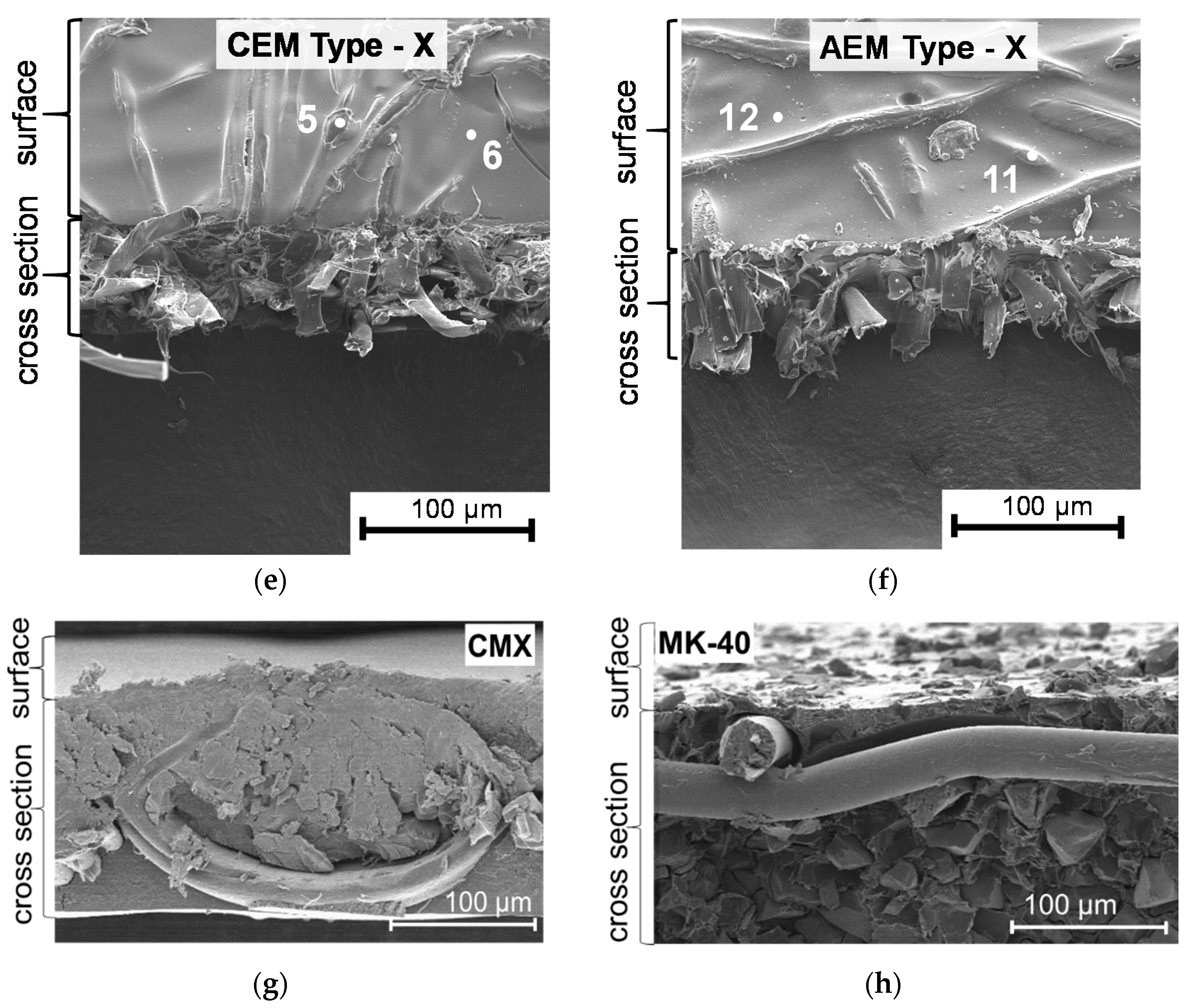
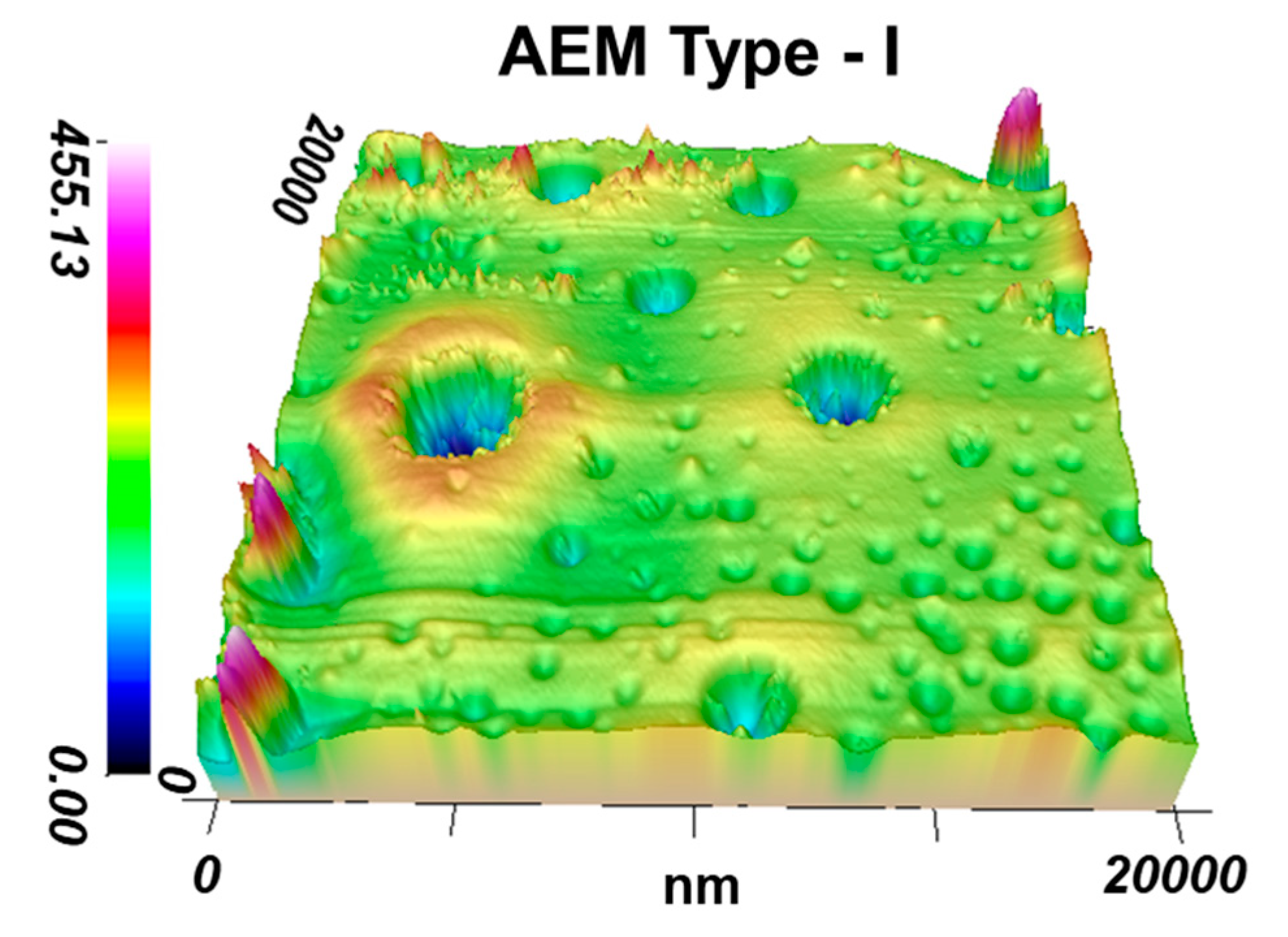
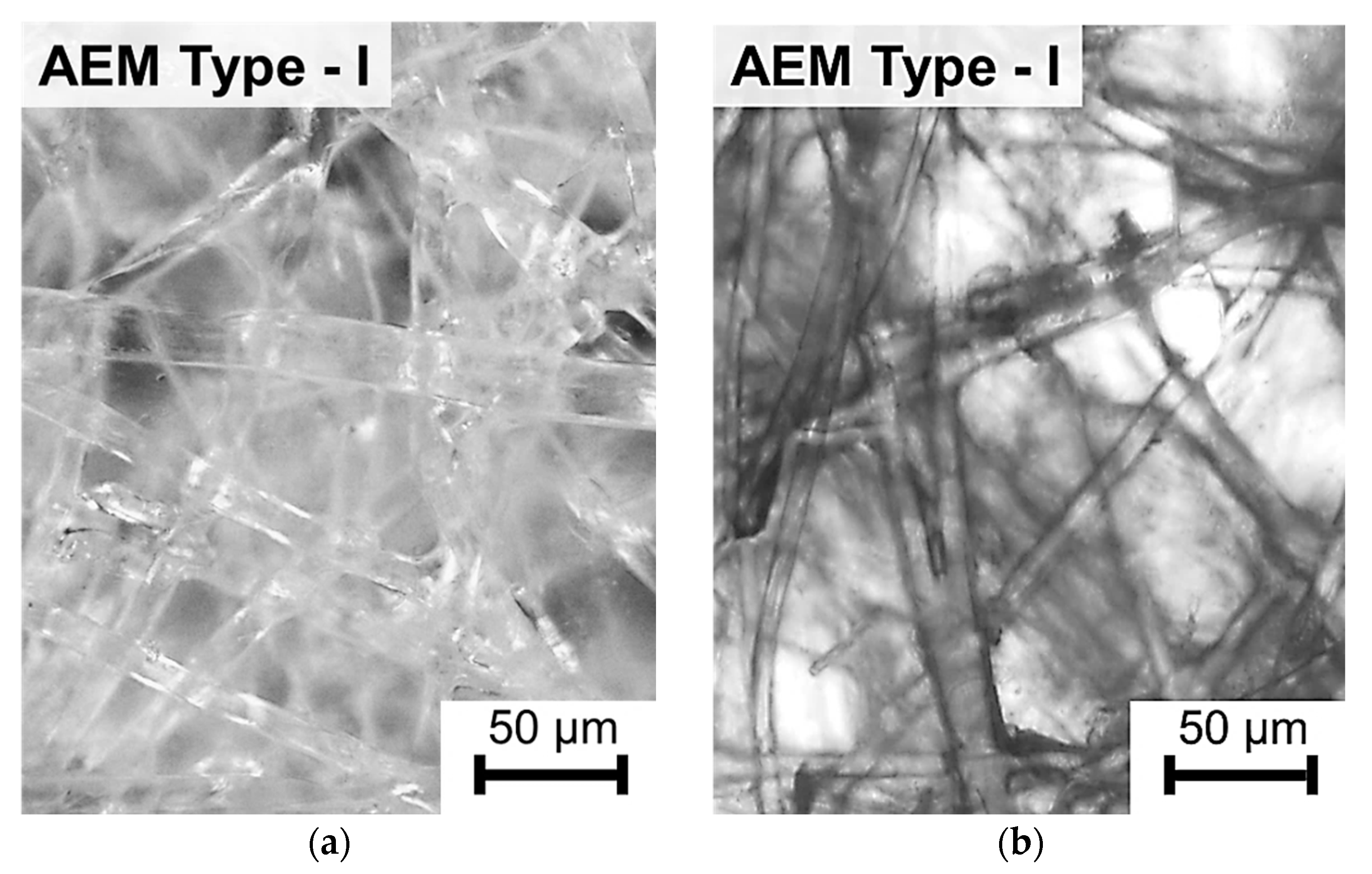
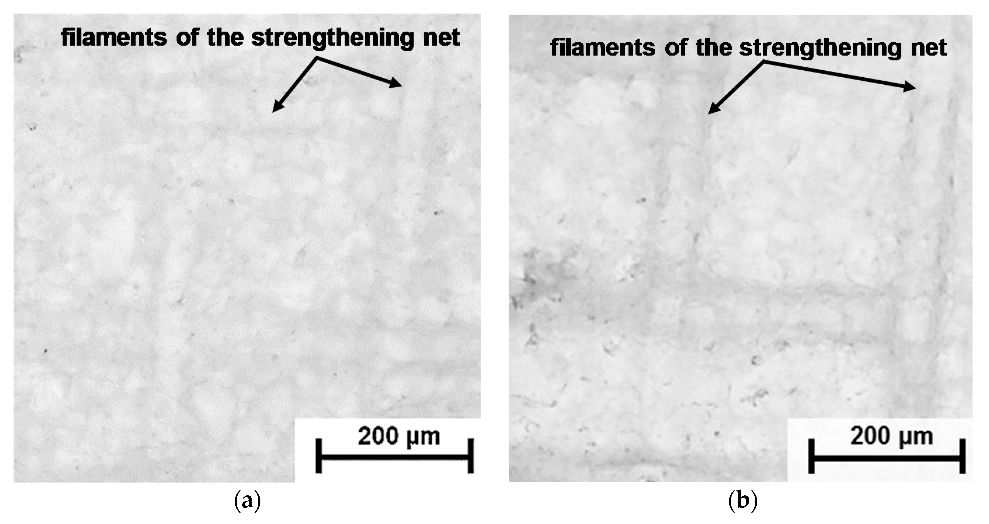
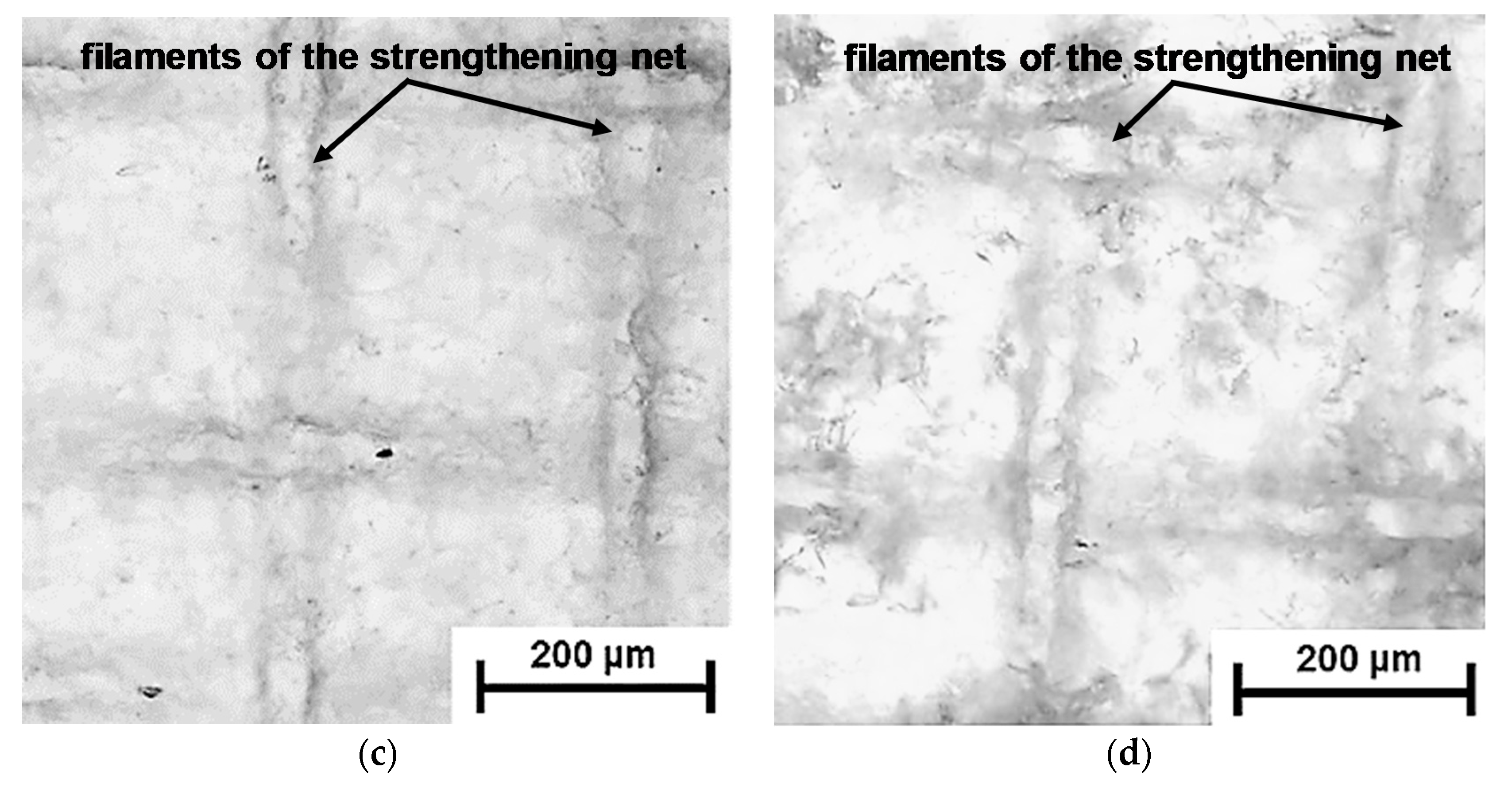
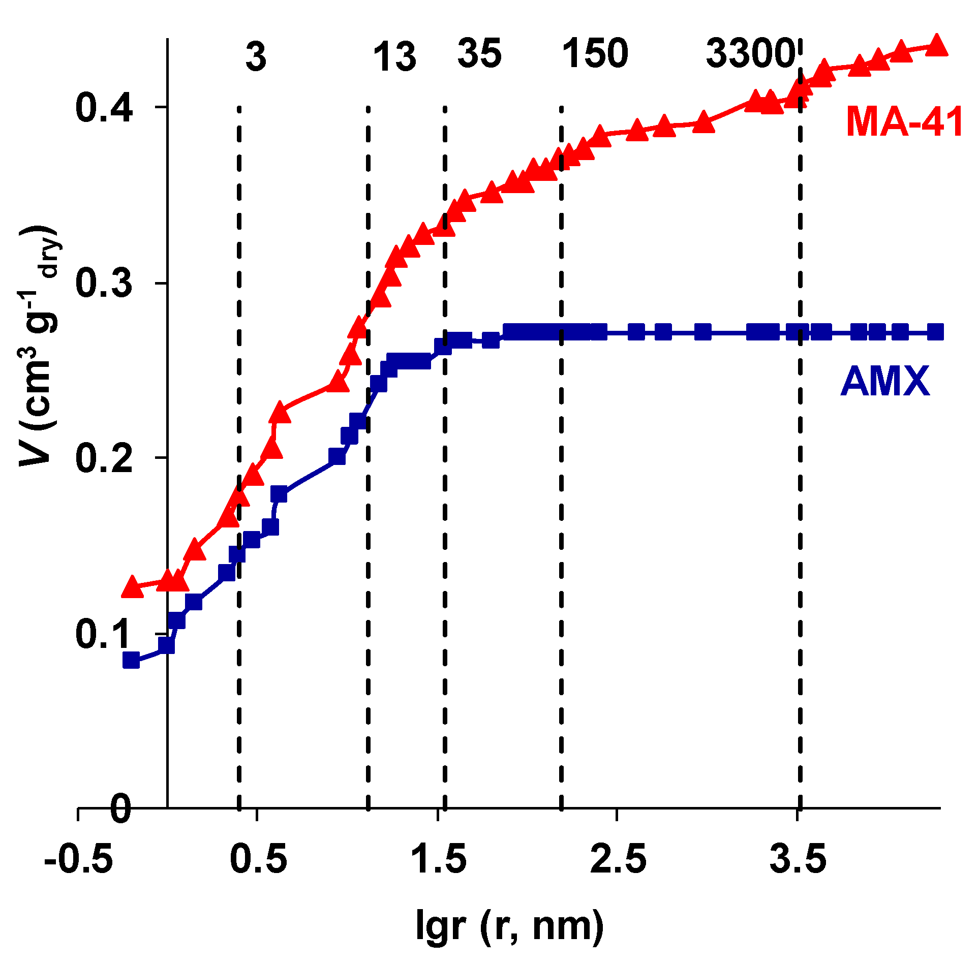
3.1. Structural Characteristics of the Investigated Membranes
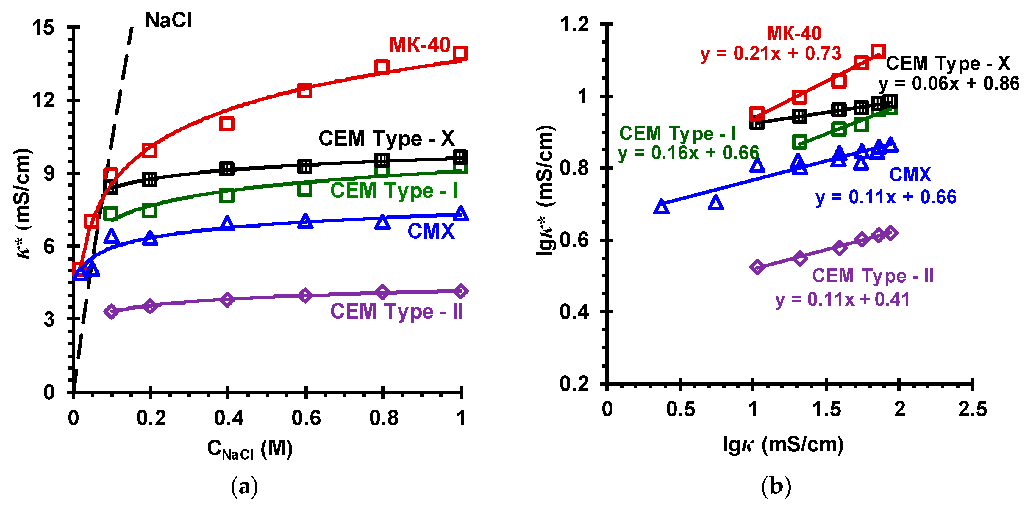
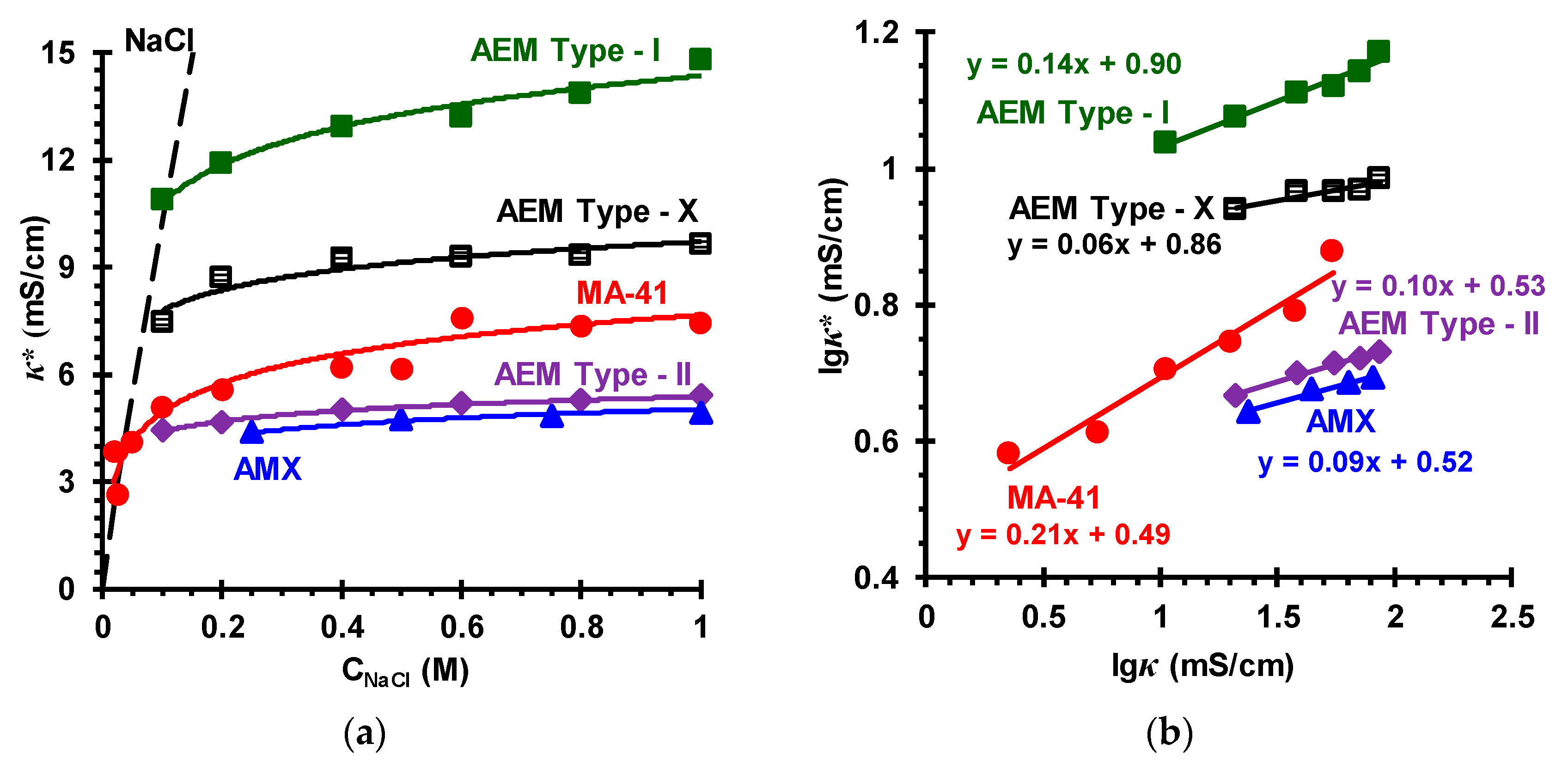
3.2. Membrane Transport Characteristics
4. Conclusions
Supplementary Materials
Author Contributions
Funding
Conflicts of Interest
References
- Ran, J.; Wu, L.; He, Y.; Yang, Z.; Wang, Y.; Jiang, C.; Ge, L.; Bakangura, E.; Xu, T. Ion exchange membranes: New developments and applications. J. Membr. Sci. 2017, 522, 267–291. [Google Scholar] [CrossRef]
- Calvo, E.J. Electrochemical methods for sustainable recovery of lithium from natural brines and battery recycling. Curr. Opin. Electrochem. 2019, 15, 102–108. [Google Scholar] [CrossRef]
- Pawlowski, S.; Crespo, J.G.; Velizarov, S. Profiled ion exchange membranes: A comprehensible review. Int. J. Mol. Sci. 2019, 20, 165. [Google Scholar] [CrossRef]
- Lee, S.; Choi, J.; Park, Y.-G.; Shon, H.; Ahn, C.H.; Kim, S.-H. Hybrid desalination processes for beneficial use of reverse osmosis brine: Current status and future prospects. Desalination 2019, 104, 104–111. [Google Scholar] [CrossRef]
- Bazinet, L.; Doyen, A. Antioxidants, mechanisms, and recovery by membrane processes. Crit. Rev. Food Sci. Nutr. 2017, 57, 677–700. [Google Scholar] [CrossRef] [PubMed]
- Kim, M.-S.; Na, J.-G.; Lee, M.-K.; Ryu, H.; Chang, Y.-K.; Triolo, J.M.; Yun, Y.-M.; Kim, D.-H. More value from food waste: Lactic acid and biogas recovery. Water Res. 2016, 96, 208–216. [Google Scholar] [CrossRef] [PubMed]
- Xie, M.; Shon, H.K.; Gray, S.R.; Elimelech, M. Membrane-based processes for wastewater nutrient recovery: Technology, challenges, and future direction. Water Res. 2016, 89, 210–221. [Google Scholar] [CrossRef] [Green Version]
- Mikhaylin, S.; Bazinet, L. Fouling on ion-exchange membranes: Classification, characterization and strategies of prevention and control. Adv. Colloid Interface 2016, 229, 34–56. [Google Scholar] [CrossRef]
- Berezina, N.P.; Kononenko, N.A.; Dyomina, O.A.; Gnusin, N.P. Characterization of ion-exchange membrane materials: Properties vs. structure. Adv. Colloid Interface 2008, 139, 3–28. [Google Scholar] [CrossRef]
- Xu, T. Ion exchange membranes: State of their development and perspective. J. Membr. Sci. 2005, 263, 1–9. [Google Scholar] [CrossRef]
- Logan, B.E.; Elimelech, M. Membrane-based processes for sustainable power generation using water. Nature 2012, 488, 313–319. [Google Scholar] [CrossRef] [PubMed]
- Ion Exchange Membranes for Water Purification. Brochure of Fujifilm Membrane Technology. Version Number 1.0. 2018. Available online: https://www.fujifilmmembranes.com/water-membranes/ion-exchange-membranes (accessed on 14 June 2019).
- Cavaliere, S.; Subianto, S.; Savych, I.; Jones, D.J.; Rozièe, J. Electrospinning: Designed architectures for energy conversion and storage devices. Energy Environ. Sci. 2011, 4, 4761–4785. [Google Scholar] [CrossRef]
- University of Delaware. Method of Solution Preparation of Polyolefin Class Polymers for Electrospinning Processing Included. U.S. Patent B29C 47178, PCT/US2006/061206, WO 2007/062393 A2, 31 May 2007. [Google Scholar]
- Tufa, R.A.; Curcio, E.; Van Baak, W.; Veerman, J.; Grasman, S.; Fontananova, E.; Di Profio, G. Potential of brackish water and brine for energy generation by salinity gradient power-reverse electrodialysis (SGPRE). RSC Adv. 2014, 4, 42617–42623. [Google Scholar] [CrossRef]
- Vermaas, D.A.; Saakes, M.; Nijmeijer, K. Doubled power density from salinity gradients at reduced intermembrane distance. Environ. Sci. Technol. 2011, 45, 7089–7095. [Google Scholar] [CrossRef]
- Tedesco, M.; Cipollina, A.; Tamburini, A.; Micale, G. Towards 1 kW power production in a reverse electrodialysis pilot plant with saline waters and concentrated brines. J. Membr. Sci. 2017, 522, 226–236. [Google Scholar] [CrossRef] [Green Version]
- Tamura, T.; Kawakami, H. Aligned electrospun nanofiber composite membranes for fuel cell electrolytes. Nano Lett. 2010, 10, 1324–1328. [Google Scholar] [CrossRef]
- Bhadja, V.; Makwana, B.S.; Maiti, S.; Sharma, S.; Chatterjee, U. Comparative efficacy study of different types of ion exchange membranes for production of ultrapure water via electrodeionization. Ind. Eng. Chem. Res. 2015, 54, 10974–10982. [Google Scholar] [CrossRef]
- Bhadja, V.; Trivedi, J.S.; Chatterjee, U. Efficacy of polyethylene interpolymer membranes for fluoride and arsenic ion removal during desalination of water: Via electrodialysis. RSC Adv. 2016, 6, 67118–67126. [Google Scholar] [CrossRef]
- Higa, M.; Tanaka, N.; Nagase, M.; Yutani, K.; Kameyama, T.; Takamura, K.; Kakihana, Y. Electrodialytic properties of aromatic and aliphatic type hydrocarbon-based anion-exchange membranes with various anion-exchange groups. Polymer 2014, 55, 3951–3960. [Google Scholar] [CrossRef]
- Tanaka, N.; Nagase, M.; Higa, M. Organic fouling behavior of commercially available hydrocarbon-based anion-exchange membranes by various organic-fouling substances. Desalination 2012, 296, 81–86. [Google Scholar] [CrossRef]
- Rijnaarts, T.; Moreno, J.; Saakes, M.; de Vos, W.M.; Nijmeijer, K. Role of anion exchange membrane fouling in reverse electrodialysis using natural feed waters. Colloid Surf. A 2019, 560, 198–204. [Google Scholar] [CrossRef]
- Choi, J.; Lee, K.M.; Wycisk, R.; Pintauro, P.N.; Mather, P.T. Nanofiber network ion-exchange membranes. Macromolecules 2008, 41, 4569–4572. [Google Scholar] [CrossRef]
- Park, A.M.; Turley, F.E.; Wycisk, R.J.; Pintauro, P.N. Electrospun and cross-linked nanofiber composite anion exchange membranes. Macromolecules 2013, 47, 227–235. [Google Scholar] [CrossRef]
- Zhang, W.; Ma, J.; Wang, P.; Wang, Z.; Shi, F.; Liu, H. Investigations on the interfacial capacitance and the diffusion boundary layer thickness of ion exchange membrane using electrochemical impedance spectroscopy. J. Membr. Sci. 2016, 502, 37–47. [Google Scholar] [CrossRef]
- Fontananova, E.; Messana, D.; Tufa, R.A.; Nicotera, I.; Kosma, V.; Curcio, E.; van Baak, W.; Drioli, E.; Di Profio, G. Effect of solution concentration and composition on the electrochemical properties of ion exchange membranes for energy conversion. J. Power Sources 2017, 340, 282–293. [Google Scholar] [CrossRef]
- Liu, H.; Ruan, H.; Zhao, Y.; Pan, J.; Sotto, A.; Gao, C.; der Bruggen, B.V.; Shen, J. A facile avenue to modify polyelectrolyte multilayers on anion exchange membranes to enhance monovalent selectivity and durability simultaneously. J. Membr. Sci. 2017, 543, 310–318. [Google Scholar] [CrossRef]
- Pan, J.; He, Y.; Wu, L.; Jiang, C.; Wu, B.; Mondal, A.N.; Cheng, C.; Xu, T. Anion exchange membranes from hot-pressed electrospun QPPO–SiO2 hybrid nanofibers for acid recovery. J. Membr. Sci. 2015, 480, 115–121. [Google Scholar] [CrossRef]
- Pan, J.; Ge, L.; Lin, X.; Wu, L.; Wu, B.; Xu, T. Cation exchange membranes from hot-pressed electrospun sulfonated poly(phenylene oxide) nanofibers for alkali recovery. J. Membr. Sci. 2014, 470, 479–485. [Google Scholar] [CrossRef]
- Güler, E.; van Baak, W.; Saakes, M.; Nijmeijer, K. Monovalent-ion-selective membranes for reverse electrodialysis. J. Membr. Sci. 2014, 455, 254–270. [Google Scholar] [CrossRef]
- Huang, Z.-M.; Zhang, Y.-Z.; Kotaki, M.; Ramakrishna, S. A review on polymer nanofibers by electrospinning and their applications in nanocomposites. Compos. Sci. Technol. 2003, 63, 2223–2253. [Google Scholar] [CrossRef]
- Zhang, C.-L.; Yu, S.-H. Nanoparticles meet electrospinning: Recent advances and future prospects. Chem. Soc. Rev. 2014, 43, 4423–4448. [Google Scholar] [CrossRef] [PubMed]
- Zhao, W.; Nugay, I.I.; Yalcin, B.; Cakmak, M. Flexible, stretchable, transparent and electrically conductive polymer films via a hybrid electrospinning and solution casting process: In-plane anisotropic conductivity for electro-optical applications. Displays 2016, 45, 48–57. [Google Scholar] [CrossRef]
- Zhu, Y.; Ahmad, M.; Yang, L.; Misovich, M.; Yaroshchuk, A.; Bruening, M.L. Adsorption of polyelectrolyte multilayers imparts high monovalent/divalent cation selectivity to aliphatic polyamide cation-exchange membranes. J. Membr. Sci. 2017, 537, 177–185. [Google Scholar] [CrossRef]
- FujiFilm Manufacturing Europe. Curable Compositions and Membranes. BV (NL) Patent C08F 20/36, PCT/GB2012/051569, WO 2013/011273, 24 January 2013. [Google Scholar]
- Mizutani, Y.; Yamane, R.; Ihara, H.; Motomura, H. Studies of ion exchange membranes. XVI. The preparation of ion exchange membranes by the “paste method”. Bull. Chem. Soc. Jpn. 1963, 36, 361–366. [Google Scholar] [CrossRef]
- Doi, S.; Yasukawa, M.; Kakihana, Y.; Higa, M. Alkali attack on anion exchange membranes with PVC backing and binder: Effect on performance and correlation between them. J. Membr. Sci. 2019, 573, 85–96. [Google Scholar] [CrossRef]
- Hori, Y.; Nakatani, T.; Mizutane, Y. Morphology of ion exchange membranes. J. Electron. Microsc. 1986, 35, 220–226. [Google Scholar]
- Pismenskaya, N.D.; Nikonenko, V.V.; Melnik, N.A.; Shevtsova, K.A.; Belova, E.I.; Pourcelly, G.; Cot, D.; Dammak, L.; Larchet, C. Evolution with time of hydrophobicity and microrelief of a cation-exchange membrane surface and its impact on overlimiting mass transfer. J. Phys. Chem. 2012, 116, 2145–2161. [Google Scholar] [CrossRef] [PubMed]
- Nefedova, G.Z.; Klimova, Z.G.; Sapozhnikova, G.S. Ion-Exchange Membranes, Granulates, Powders: Catalogue; NIITEKhim: Moscow, Russia, 1977. [Google Scholar]
- Rijnaarts, T.; Huerta, E.; van Baak, W.; Nijmeijer, K. Effect of divalent cations on RED performance and cation exchange membrane selection to enhance power densities. Environ. Sci. Technol. 2017, 51, 13028–13035. [Google Scholar] [CrossRef] [PubMed]
- Káňavová, N.; Krejčí, A.; Benedeková, M.; Doležel, M.; Machuča, L. Mass transfer examination in electrodialysis using limiting current measurements. Chem. Pap. 2015, 69, 553–559. [Google Scholar] [CrossRef]
- Safronova, E.Y.; Golubenko, D.V.; Shevlyakova, N.V.; D’yakova, M.G.; Tverskoi, V.A.; Dammak, L.; Grande, D.; Yaroslavtsev, A.B. New cation-exchange membranes based on cross-linked sulfonated polystyrene and polyethylene for power generation systems. J. Membr. Sci. 2016, 515, 196–203. [Google Scholar] [CrossRef]
- Balster, J.; Krupenko, O.; Pünt, I.; Stamatialis, D.F.; Wessling, M. Preparation and characterisation of monovalent ion selective cation exchange membranes based on sulphonated poly(ether ether ketone). J. Membr. Sci. 2005, 263, 137–145. [Google Scholar] [CrossRef]
- Sedkaoui, Y.; Szymczyk, A.; Lounici, H.; Arous, O. A new lateral method for characterizing the electrical conductivity of ion-exchange membranes. J. Membr. Sci. 2016, 507, 34–42. [Google Scholar] [CrossRef]
- Jiang, C.; Wang, Y.; Zhang, Z.; Xu, T. Electrodialysis of concentrated brine from RO plant to produce coarse salt and freshwater. J. Membr. Sci. 2014, 450, 323–330. [Google Scholar] [CrossRef]
- Karpenko-Jereb, L.V.; Berezina, N.P. Determination of structural, selective, electrokinetic and percolation characteristics of ion-exchange membranes from conductive data. Desalination 2009, 245, 587–596. [Google Scholar] [CrossRef]
- Tourreuil, V.; Rossignol, N.; Bulvestre, G.; Larchet, C.; Auclair, B. Determination of the selectivity of an ion-exchange membrane - comparison of diffusion flux and transport number. Eur. Polym. J. 1998, 34, 1415–1421. [Google Scholar] [CrossRef]
- Drioli, E.; Giorno, L.; Fontananova, E. Comprehensive Membrane Science and Engineering; Elsevier Science: Amsterdam, The Netherlands, 2017; ISBN 9780444637758. [Google Scholar]
- Hannachi, C.; Ali, M.B.S.; Hamrouni, B. Determination of the selectivity coefficient of the CMX cationic membrane at various ionic strengths. Desalin. Water Treat. 2009, 10, 47–52. [Google Scholar] [CrossRef]
- Długołecki, P.; Anet, B.; Metz, S.J.; Nijmeijer, K.; Wessling, M. Transport limitations in ion exchange membranes at low salt concentrations. J. Membr. Sci. 2010, 346, 163–171. [Google Scholar] [CrossRef]
- Zhou, J.; Kuang, H.; Zhuang, W.; Chen, Y.; Liu, D.; Ying, H.; Wu, J. Application of electrodialysis to extract 5′-ribonucleotides from hydrolysate: Efficient decolorization and membrane fouling. RSC Adv. 2018, 8, 29115–29128. [Google Scholar] [CrossRef]
- Jaroszek, H.; Dydo, P. Potassium nitrate synthesis by electrodialysis-metathesis: The effect of membrane type. J. Membr. Sci. 2018, 549, 28–37. [Google Scholar] [CrossRef]
- Vasil’eva, V.I.; Pismenskaya, N.D.; Akberova, E.M.; Nebavskaya, K.A. Effect of thermochemical treatment on the surface morphology and hydrophobicity of heterogeneous ion-exchange membranes. Rus. J. Phys. Chem. A 2014, 88, 1293–1299. [Google Scholar] [CrossRef]
- Berezina, N.; Gnusin, N.; Dyomina, O.; Timofeyev, S. Water electrotransport in membrane systems. Experiment and model description. J. Membr. Sci. 1994, 86, 207–229. [Google Scholar] [CrossRef]
- Gnusin, N.P.; Berezina, N.P.; Kononenko, N.A.; Dyomina, O.A. Transport structural parameters to characterize ion exchange membranes. J. Membr. Sci. 2004, 243, 301–310. [Google Scholar] [CrossRef]
- Tuan, L.X. Permselectivity and microstructure of anion exchange membranes. J. Colloid Interface 2008, 325, 215–222. [Google Scholar]
- Zabolotsky, V.I.; Nikonenko, V.V. Effect of structural membrane inhomogeneity on transport properties. J. Membr. Sci. 1993, 79, 181–198. [Google Scholar] [CrossRef]
- Nagarale, R.K.; Gohil, G.S.; Shahi, V.K. Recent developments on ion-exchange membranes and electro-membrane processes. Adv. Colloid Interface 2006, 119, 97–130. [Google Scholar] [CrossRef] [PubMed]
- Belashova, E.D.; Melnik, N.A.; Pismenskaya, N.D.; Shevtsova, K.A.; Nebavsky, A.V.; Lebedev, K.A.; Nikonenko, V.V. Overlimiting mass transfer through cation-exchange membranes modified by Nafion film and carbon nanotubes. Electrochim. Acta 2012, 59, 412–423. [Google Scholar] [CrossRef]
- Kamusewitz, H.; Schossig-Tiedemann, M.; Keller, M.; Paul, D. Characterization of polymeric membranes by means of scanning force microscopy (SFM) in comparison to results of scanning electron microscopy (SEM). Surf. Sci. 1997, 377–379, 1076–1081. [Google Scholar] [CrossRef]
- Schossig-Tiedemann, M.; Paul, D. Improved preparation of membrane surfaces for field-emission scanning electron microscopy. J. Membr. Sci. 2001, 187, 85–91. [Google Scholar] [CrossRef]
- Sheldeshov, N.V.; Ganych, V.V.; Zabolotsky, V.I. Transport numbers of salt ions and water dissociation products in cation and anion-exchange membranes. Sov. Electrochem. 1991, 23, 11–15. [Google Scholar]
- Lteif, R.; Dammak, L.; Larchet, C.; Auclair, B. Conductivité électrique membranaire: Étude de l’effet de la concentration, de la nature de l’électrolyte et de la structure membranaire. Eur. Polym. J. 1999, 35, 1187–1195. [Google Scholar] [CrossRef]
- Karpenko, L.V.; Demina, O.A.; Dvorkina, G.A.; Parshikov, S.B.; Larchet, C.; Auclair, B.; Berezina, N.P. Comparative study of methods used for the determination of electroconductivity of ion-exchange membranes. Russ. J. Electrochem. 2001, 37, 287–293. [Google Scholar] [CrossRef]
- Nikonenko, V.; Vedernikova, E.; Pismenskaya, N. Device for measurements of diffusion characteristics of membrane. Rus. Patent 100275 RF, MPK51 G01N27/40, No 2010121195/28, 10 December 2010. [Google Scholar]
- Shutkina, E.A.; Nevakshenova, E.E.; Pismenskaya, N.D.; Mareev, S.A.; Nikonenko, V.V. Diffusion permeability of the anion-exchange membranes in sodium dihydrogen phosphate solution. Condens. Matter Interphases 2015, 17, 566–578. [Google Scholar]
- Larchet, C.; Auclair, B.; Nikonenko, V. Approximate evaluation of water transport number in ion-exchange membranes. Electrochim. Acta 2004, 49, 1711–1717. [Google Scholar] [CrossRef]
- Gnusin, N.P.; Berezina, N.P.; Shudrenko, А.А.; Ivina, O.P. Electrolyte diffusion across ion-exchange membranes. Russ. J. Phys. Chem. A 1994, 68, 565. [Google Scholar]
- Helfferich, F.G. Ion Exchange; ASIN: B0000CLGWI; McGraw-Hill: New York, NY, USA, 1962. [Google Scholar]
- Volfkovich, Y.M.; Bagotzky, V.S.; Sosenkin, V.E.; Blinov, I.A. The standard contact porosimetry. Colloid Surf. A 2001, 187–188, 349–365. [Google Scholar] [CrossRef]
- Kononenko, N.; Nikonenko, V.; Grande, D.; Larchet, C.; Dammak, L.; Fomenko, M.; Volfkovich, Y. Porous structure of ion exchange membranes investigated by various techniques. Adv. Colloid Interface 2017, 246, 196–216. [Google Scholar] [CrossRef] [PubMed]
- Kozmai, A.E.; Nikonenko, V.V.; Zyryanova, S.; Pismenskaya, N.D.; Dammak, L. A simple model for the response of an anion-exchange membrane to variation in concentration and pH of bathing solution. J. Membr. Sci. 2018, 567, 127–138. [Google Scholar] [CrossRef]
- Choi, J.-H.; Moon, S.-H. Structural change of ion-exchange membrane surfaces under high electric field and its effect on membrane properties. J. Colloid Interface 2003, 265, 93–100. [Google Scholar] [CrossRef]
- Merle, G.; Wessling, M.; Nijmeijer, K. Anion exchange membranes for alkaline fuel cells: A review. J. Membr. Sci. 2011, 377, 1–35. [Google Scholar] [CrossRef]
- Elattar, A.; Elmidaoui, A.; Pismenskaia, N.; Gavach, C.; Pourcelly, G. Comparison of transport properties of monovalent anions through anion-exchange membranes. J. Membr. Sci. 1998, 143, 249–261. [Google Scholar] [CrossRef]
- Belova, E.I.; Lopatkova, G.Y.; Pismenskaya, N.D.; Nikonenko, V.V.; Larchet, C.; Pourcelly, G. Effect of anion-exchange membrane surface properties on mechanisms of overlimiting mass transfer. J. Phys. Chem. B 2006, 110, 13458–13469. [Google Scholar] [CrossRef] [PubMed]
- Luo, T.; Abdu, S.; Wessling, M. Selectivity of ion exchange membranes: A review. J. Membr. Sci. 2018, 555, 429–454. [Google Scholar] [CrossRef]
- Hladik, J. Physics of Electrolytes; Academic Press: London, UK, 1972; ISBN 10 0123498015. [Google Scholar]
- Duke, M.; Zhao, D.; Semiat, R. Functional Nanostructured Materials and Membranes for Water Treatment; Wiley-VCH Verlag & Co. KgaA: Weinheim, Germany, 2013; ISBN 978-3-527-32987-8. [Google Scholar]
- Vasil’eva, V.I.; Akberova, E.M.; Zabolotsky, V.I.; Goleva, E.A.; Yatsev, A.M. Method of Modification of Sulfonated Cation-Exchange Membrane for High-Intensity Electrodialysis. Rus. Patent 2677202C2 RF, MPK B01D69/00, B01D 61/44, 24 May 2017. [Google Scholar]
- Lteif, R.; Dammak, L.; Larchet, C.; Auclair, B. Détermination du nombre de transport d’un contre-ion dans une membrane échangeuse d’ions en utilisant la méthode de la pile de concentration. Eur. Polym. J. 2001, 37, 627–639. [Google Scholar] [CrossRef]
- Moreno, J.; Grasman, S.; van Engelen, R.; Nijmeijer, K. Upscaling reverse electrodialysis. Environ. Sci. Technol. 2018, 52, 10856–10863. [Google Scholar] [CrossRef] [PubMed]
- Akberova, E.M. Structural Effects of Thermochemical Modification of Heterogeneous Ion-Exchange Membranes. Ph.D. Thesis, Voronezh State University, Voronezh, Russia, 2015. [Google Scholar]


| Membranes | Type | Ion Exchange Matrix | Fixed Groups | Inert Binder | Reinforcing Material | Manufac-Turing Method |
|---|---|---|---|---|---|---|
| MA-41 | heterogeneous | DVB + PS | * | PE | nylon mesh | hot rolling |
| MK-40 | ** | |||||
| AMX | homogeneous | * | PVC | PVC fabric | “paste” method | |
| CMX | ** | |||||
| АЕМ Type-I, AEM Type-II, AEM Type-Х | PA | * | - | 3D polyolefin fibers structure | filling the voids of the 3D fiber structure with ion-exchange material | |
| CEM Type-I, CEM Type-II, CEM Type-Х | ** |
| Membranes | Thickness of Air-Dried Membrane, Microns | * Thickness of Wet Membrane, Microns | Exchange Capacity, mmol g−1 wet | Density, g cm−3 wet | Water Content, g Н2О/g wet, % | Water Content, mol H2O/mol Functional Groups |
|---|---|---|---|---|---|---|
| Cation-Exchange | ||||||
| CEM Type-I | 120 ± 5 115 [42] | 140 ± 10 | 1.43 ± 0.05 | 1.15 | 29 ± 5 | 11.3 ± 1 |
| CEM Type-II | 165 ± 5 | 180 ± 10 179 [43] | 1.35 ± 0.05 | 1.13 | 25 ± 2 | 10.3 ± 1 |
| CEM Type-X | 125 ± 5 125 [42] | 130 ± 5 | 1.67 ± 0.05 | 1.20 | 21 ± 5 | 7 ± 1 |
| CMX | 155 ± 5 155 [42] | 170 ± 5 175 ± 6 [44] 163 [45] | 1.61 ± 0.05 1.65 ± 0.05 [46] 1.62 ± 0.04 [31,47] | 1.32 1.19 [48] 1.26 [49] | 22 ± 3 19 [50] 23 [51] | 8 ± 1 (7.5) 7.62 [52,53] 9 [54] |
| MK-40 | 440 ± 10 | 520 ± 20 520 ± 10 [55] | 1.43 ± 0.08 1.52 ± 0.08 [55] 1.69 [48] | 1.18 1.13 [48] 1.19 [55] | 26 ± 5 34.7 [56] 33 ± 1 [55] | 10 ± 1 12.1 ± 1 11.8 [57] |
| Anion-Exchange | ||||||
| AEM Type-I | 120 ± 5 115 [42] | 125 ± 5 | 1.50 ± 0.05 | 1.06 | 8 ± 2 | 3.3 ± 1 |
| AEM Type-II | 165 ± 5 130 [19] | 175 ± 5 175 [43] | 1.08 ± 0.05 | 1.06 | 10 ± 5 | 5.5 ± 1 |
| AEM Type-X | 115 ± 5 125 [42] | 120 ± 5 | 1.50 ± 0.05 | 1.08 | 23 ± 2 | 8.7 ± 1 |
| AMX | 125 ± 5 | 135 ± 5 141 ± 6 [23] | 1.23 ± 0.05 1.25 [47] | 1.22 1.10 [58] | 14 ± 2 16 [50] | 6.5 ± 1 6.1 [23] 7.8 [54] |
| MA-41 | 430 ± 10 | 450 ± 50 530 ± 20 [55] | 1.22 ± 0.06 1.18 ± 0.06 [55] 1.25 [46] | 1.06 1.14 [59] | 30 ± 2 30 [56] 35 ± 2 [55] | 8.7 ± 1 13 [56] 7.1 [23] |
| Membranes | Elemental Composition (%) | Q, mmol g−1dry | |||||
|---|---|---|---|---|---|---|---|
| Carbon (С1s) | Oxygen (О1s) | Nitrogen (N1s) | Chlorine (Cl2p) | Sulfur (S2p) | |||
| Cation-Exchange Membranes | |||||||
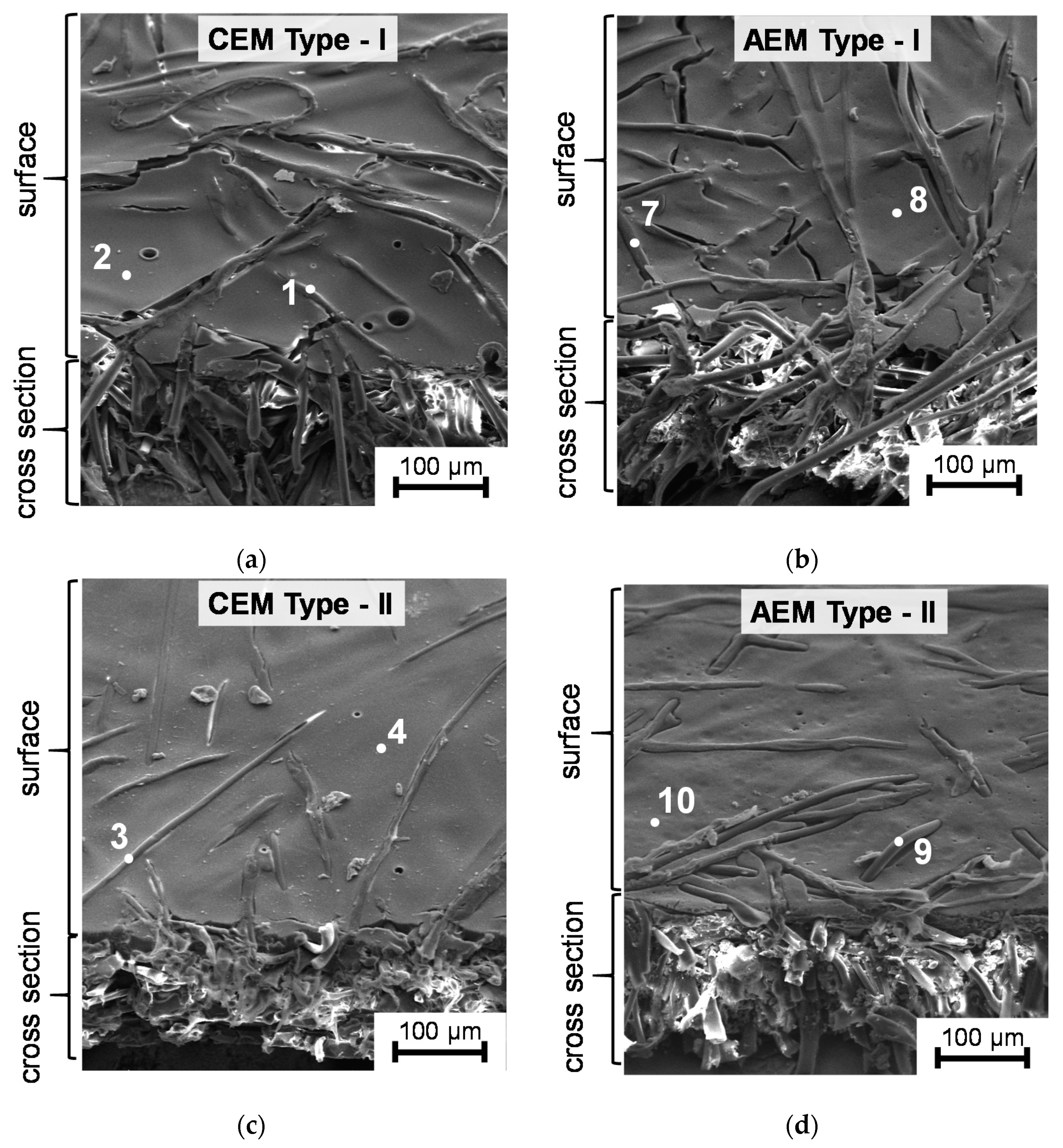
| CEM Type-I | * 1 | 99 | 1 | - | - | - | 2.02 ± 0.05 |
| 2 | 54 | 26 | 11 | - | 9 | ||
| CEM Type-II | 3 | 99 | 1 | - | - | - | 1.81 ± 0.05 |
| 4 | 50 | 32 | 10 | - | 8 | ||
| CEM Type-X | 5 | 100 | - | - | - | - | 2.12 ± 0.05 |
| 6 | 52 | 27 | 8 | - | 13 | ||
| Anion-Exchange Membranes | |||||||
| AEM Type-I | 7 | 99 | 1 | - | - | - | 1.65 ± 0.05 |
| 8 | 57 | 21 | 16 | 6 | - | ||
| AEM Type-II | 9 | 99 | 1 | - | - | - | 1.21 ± 0.05 |
| 10 | 63 | 19 | 14 | 4 | - | ||
| AEM Type-X | 11 | 100 | - | - | - | - | 1.96 ± 0.05 |
| 12 | 75 | 5 | 13 | 7 | - | ||
| Membranes | f2 | , mS cm−1 | , mmol cm−3wet gel | , m2 s−1 |
|---|---|---|---|---|
| Cation-Exchange Membranes | ||||
| CEM Type-I | 0.16 ± 0.1 | 6.1 ± 0.1 | 1.65 ± 0.05 | 0.67 |
| CEM Type-II | 0.11 ± 0.01 | 2.8 ± 0.1 | 1.53 ± 0.05 | 0.36 |
| CEM Type-X | 0.06 ± 0.01 | 8.2 ± 0.1 | 2.01 ± 0.05 | 0.97 |
| CMX | 0.11 ± 0.03 0.06 [57] 0.10 [46] | 5.5 ± 0.1 6.72 [57] 8.79 [46] | 2.13 ± 0.05 | 0.63 |
| MK-40 | 0.21 ± 0.03 0.25 [46] 0.18 [57] 0.20 [56] | 8.3 ± 0.1 5.27 [57] 6.4 [56] | 1.74 ± 0.05 | 0.88 |
| Anion-Exchange Membranes | ||||
| AEM Type-I | 0.14 ± 0.03 | 10.9 ± 0.1 | 1.60 ± 0.05 | 1.52 |
| AEM Type-II | 0.11 ± 0.02 | 3.9 ± 0.1 | 1.14 ± 0.05 | 0.76 |
| AEM Type-X | 0.06 ± 0.02 | 8.3 ± 0.1 | 1.63 ± 0.05 | 1.05 |
| AMX | 0.09 ± 0.03 0.11 [46] | 3.7 ± 0.1 3.72 [46] 4.3 [77] | 1.50 ± 0.05 | 0.62 |
| MA-41 | 0.21 ± 0.03 0.24 [46] 0.18 [57] | 4.2 ± 0.1 4.0 [46] 5.8 [57] 6.3 [56] | 1.30 ± 0.05 | 0.58 |
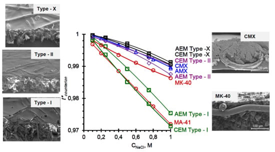
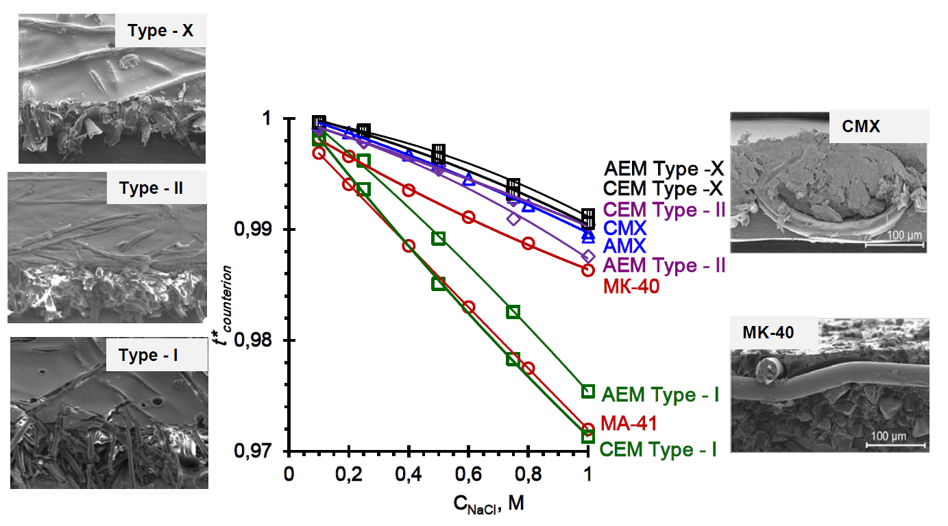
| Membranes | tw | ||
|---|---|---|---|
| Cation-exchange Membranes | |||
| CEM Type-I | 0.985 | 0.950 [12] | 3.9 |
| CEM Type-II | 0.996 | 0.976 [12] | 2.2 |
| CEM Type-X | 0.996 | 0.994 [12] | 0.2 |
| CMX | 0.995 | 0.98 [81] 0.965 [2] (NaCl) | 1.7 |
| MK-40 | 0.992 | 0.94 [36] 0.95 [82] 0.965 [83] (KCl) | 5.8 6.5 [56] |
| Anion-Exchange Membranes | |||
| AEM Type-I | 0.989 | 0.950 [12] | 4.3 |
| AEM Type-II | 0.995 | 0.970 [12] | 2.8 |
| AEM Type-X | 0.997 | 0.970 [12] | 3 |
| AMX | 0.996 | 0.98 [84] | 1.9 |
| МА-41 | 0.986 | 0.950 [85] | 5.1 5.0 [56] |
© 2019 by the authors. Licensee MDPI, Basel, Switzerland. This article is an open access article distributed under the terms and conditions of the Creative Commons Attribution (CC BY) license (http://creativecommons.org/licenses/by/4.0/).
Share and Cite
Sarapulova, V.; Shkorkina, I.; Mareev, S.; Pismenskaya, N.; Kononenko, N.; Larchet, C.; Dammak, L.; Nikonenko, V. Transport Characteristics of Fujifilm Ion-Exchange Membranes as Compared to Homogeneous Membranes АМХ and СМХ and to Heterogeneous Membranes MK-40 and MA-41. Membranes 2019, 9, 84. https://0-doi-org.brum.beds.ac.uk/10.3390/membranes9070084
Sarapulova V, Shkorkina I, Mareev S, Pismenskaya N, Kononenko N, Larchet C, Dammak L, Nikonenko V. Transport Characteristics of Fujifilm Ion-Exchange Membranes as Compared to Homogeneous Membranes АМХ and СМХ and to Heterogeneous Membranes MK-40 and MA-41. Membranes. 2019; 9(7):84. https://0-doi-org.brum.beds.ac.uk/10.3390/membranes9070084
Chicago/Turabian StyleSarapulova, Veronika, Inna Shkorkina, Semyon Mareev, Natalia Pismenskaya, Natalia Kononenko, Christian Larchet, Lasaad Dammak, and Victor Nikonenko. 2019. "Transport Characteristics of Fujifilm Ion-Exchange Membranes as Compared to Homogeneous Membranes АМХ and СМХ and to Heterogeneous Membranes MK-40 and MA-41" Membranes 9, no. 7: 84. https://0-doi-org.brum.beds.ac.uk/10.3390/membranes9070084