Article

Development of a Depth Control System Based on Variable-Gain Single-Neuron PID for Rotary Burying of Stubbles

1
College of Engineering, Huazhong Agricultural University, Wuhan 430070, China
2
Key Laboratory of Agricultural Equipment in Mid-Lower Yangtze River, Ministry of Agriculture and Rural Affairs, Wuhan 430070, China
*
Author to whom correspondence should be addressed.
Submission received: 20 November 2021 / Revised: 15 December 2021 / Accepted: 26 December 2021 / Published: 28 December 2021

Abstract

:
Rotary burying by tractor-hitched rotary tillers is a common practice in southern China for treating rice stubbles. Currently, it is difficult to maintain stable tillage depths due to surface unevenness and the residual stubbles in the field, which leads to unstable tillage quality and nonuniform crop growth in later stages. In this study, an RTK-GNSS was used to measure the real-time height and roll angle of the tractor, and a variable-gain single-neuron PID control algorithm was designed to adjust the coefficients (KP, KI, and KD) and gain K in real-time according to the control effects. An on-board computer sent the angles of the upper swing arm u(t) to an STM32 microcontroller through a CAN bus. Compared with the current angle of the upper swing arm, the microcontroller controlled an electronic-control proportional hydraulic system, so that the height of the rotary tiller could be adjusted to follow the field undulations in real-time. Field experiments showed that when the operation speed of the tractor-rotary tiller system was about 0.61 m/s, the variable-gain single-neuron PID algorithm could effectively improve the stability of the working depth and the stubbles’ burying rate. Compared with a conventional PID controller, the stability coefficient and the stubbles’ burying rate were improved by 5.85% and 4.38%, respectively, and compared with a single-neuron PID controller, the stability coefficient and the stubbles’ burying rate were improved by 4.37% and 3.49%, respectively. This work controlled the working depth of the rotary tiller following the changes in the field surface in real-time and improved the stubbles’ burying rate, which is suitable for the unmanned operation of the rotary burying of stubbles in the future.

1. Introduction

The multi-cropping rice planting area in the middle and lower reaches of the Yangtze River is one of the main rice planting areas in China. Rotary burying of stubbles can not only improve the soil fertility and structure, but also avoid the environmental pollution caused by the burning of stubbles, so it is deemed as the preferred method for stubble treatment in this area [1]. The depth of rotary burying into the field is one of the key factors affecting the crop root growth and yields. If the tillage depth is too deep, the soil structure will be damaged and the power consumption as well as the operational cost will be increased. When it is too shallow, the absorption of nutrients by the root system will be weakened, affecting the growth of crops and failing to meet the agronomic requirements [2,3,4]. During the operation of rotary burying of stubbles, the working depth to the field is unstable due to the influence of surface unevenness, resulting in unstable operation quality [5]. Currently, the depth of rotary burying is mainly controlled by the driver’s experience, which makes it difficult to control the working depth stably and accurately.
For rotary burying of stubbles in the middle and lower reaches of the Yangtze River, Xia et al. [6] designed a spiral burying machine and performed field tests. The experimental results showed that the machine could complete burying and returning of rice straws, wheat straws, rape straws, etc. to a depth of more than 700 mm. When the tillage depth was 11 cm, the burying rate after two operations was more than 90%. Zhang et al. [7] designed a rotary burying machine for paddy fields and dry lands. A large number of tests showed that the tillage depth could reach more than 15 cm and the burying rate of stubbles was 90%, which met the requirements of the agricultural machinery standard (NY/T499-2013) for rotary tillers (the tillage depth should be greater than 12 cm and the burying rate should be greater than 80%). In light of the complex surface environment in the field, researchers have mainly used inclination sensors [8,9,10], lasers [11,12,13,14], and the global positioning and navigation system (GNSS) [15,16,17,18] to develop measurement methods of field surface data. The inclination sensor can estimate the height change of the field surface through the pitch angle of the vehicle, which is low in cost and easy to develop. However, its accuracy is low when the height change is complex. Lasers can calculate the height of the field surface accurately through the height difference between a receiver and a transmitter, but it cannot obtain other position and attitude information of the equipment. It is also difficult to work under strong lights and winds. Moreover, it is not suitable for leveling large areas and slope lands. The GNSS can obtain real-time spatial pose information and generate differential positioning signals through a receiver and a base station. It has a wide working range and high positioning accuracy. In addition, it is not susceptible to environmental factors when working [15,16].
The depth control process by the traditional mechanical hydraulic system is complex. Electronic hydraulic control systems have better flexibility and real-time performance, which is convenient for researchers to develop and apply. Compared with the hydraulic mechanical system, the electronic hydraulic control system improves the traction efficiency of tractor operation, and the tillage depths under different field conditions are more stable [17,18,19]. The field surface environment is complex after harvesting. Although the conventional PID control scheme is simple and adaptable, it has no parameter adaptive adjustment ability, and its parameter setting must be relative to a known system. The parameter setting of a conventional proportional integrative derivative (PID), which has fixed parameter values, may only be applicable to one working condition and cannot meet the control requirements in practical applications [20]. Therefore, the adaptive PID control method with adjustable parameters has been studied and applied including fuzzy PID control [21,22], expert PID control [23], and neural network-based PID control [24,25]. Zhu and Zhang [26] used MATLAB to analyze the electro-hydraulic hitch system based on a PID position control strategy. The study provided a reference for the optimization design of electronic hydraulic control systems for tractors; however, the study did not consider the actual situation of interference. Anthonis et al. [27] designed a proportional (P) controller, a lead compensator, a PID controller, and a PID controller with filtered derivative (D). The field experiment of using the tractor body angle to control the tillage depth showed that the PID controller had poor robustness. Shafaei et al. [28] developed an electronic hydraulic control system for a tractor (MF-399) based on fuzzy PID, which could control the working depth of the tools in real-time. The field experiment showed that the depth error of the fuzzy system was 53% lower than that of the original mechanical system. Han et al. [29] also proposed a hybrid traction position control strategy based on a fuzzy controller; despite that, the complex field environment increased the depth error and the response time of the control system, and the stability of the control system was improved by the control strategy. Xi [30] and Xi et al. [31] developed an electronic hydraulic hitch system based on a BP neural network. The BP neural network adjusted the mixing ratio to control the tillage depth according to the traction force and tillage depth. Although the control system was not integrated into the tractor electro-hydraulic system, the study was an exploration for future electronic hydraulic hitch control systems of tractors. The above studies show that the electro-hydraulic hitch system can improve the reliability of the tractor control system through the application of advanced control algorithms. At present, there are few studies on the tillage depth control of rotary burying of stubbles using GNSS, and there is a lack of application of mature products.
Unlike the above depth control systems, the depth control system in this study was based on an RTK-GNSS. The working depth of the rotary tiller was controlled to follow the changes in the field surface in real-time. The control algorithm was redesigned to fit the unmanned depth control operation of the rotary burying of stubbles, especially in the field with surface unevenness and residual stubbles. The main contributions of this study are summarized as follows: (1) an electronic-control hydraulic lifting system for rotary burying of stubbles based on a variable-gain single-neuron PID algorithm was designed, with advantages of precise control and fast response; and (2) a dual antenna RTK-GNSS was used to obtain the real-time surface height and roll angle of the tractor, based on which a new depth control system for rotary burying was proposed.

2. Materials and Methods

The depth control system for the rotary burying operation was mainly composed of a wheeled tractor (Dongfanghong L954, China YTO, Luoyang, China), an on-board computer, an electronic-control proportional hydraulic valve, an angle sensor, two RTK-GNSS receiving antennas, an RTK-GNSS rover station, a rotary tiller for stubble burying, and a depth controller, as shown in Figure 1. The RTK-GNSS used was the K726-OEM double antenna positioning and orientation system produced by the Shanghai Sinan Company, with a horizontal plane accuracy of 1 cm + 1 ppm, an elevation accuracy of 2 cm + 1 ppm, and a heading angle accuracy of better than 0.2°/R (R is the length of double antenna baseline, m).
The positioning and directional antennas of the GNSS were respectively placed on the left and right sides of the rear of the tractor roof (the baseline length R is 1.38 m); an electronic-control proportional hydraulic valve was installed on the lower end of the rear transmission shaft with an independently designed bracket, which was used to control the lifting of the tractor three-point hitch; an angle sensor (ANG1 series contactless angle sensor, Luoyang Meta Electronic Control Technology Co. Ltd. (Luoyang, China), range −180°~180°, accuracy 0.05%, resolution 0.025%) was connected with the rotating shaft of the upper swing arm of the tractor three-point hitch; an RTK-GNSS rover station and an STM32 microcontroller were placed in the cab of the tractor. A rotary tiller for stubble burying was hitched at the back of the tractor, and its main structural parameters are shown in Table 1. An on-board computer was controlled by the operator to start and stop the tillage depth control system and store the height data of the field and tiller in real-time.

2.1. Depth Control System Structure

As shown in Figure 2, the structure of the rotary burying depth control system was composed of a status acquisition system, a control system, and a lifting system. The pose acquisition system used a dual-antenna RTK-GNSS to obtain the height, speed, and roll angle information, and used an angle sensor to obtain the lifting angles of the upper bent arm of the tractor’s rear suspension in real-time. The control system used an on-board computer to record information of heights and lifting angles in real-time and output the control depths for the tiller through the control algorithm. The depth control signals output by the on-board computer through the USB port were converted into CAN signals by a CAN analyzer (USBCAN/CANalyst-II, Zhuhai Chuangxin Technology, Zhuhai, China), and were then sent to an STM32 microcontroller by the CAN bus. Compared with the angle of the upward swing arm at the current moment sent by the angle sensor, the final executive depth was determined. In the lifting system, the STM32 microcomputer controlled the port status of the solenoid valve of the electronic-control proportional hydraulic valve. Finally, the hydraulic oil flowed into the steering hydraulic cylinder to control the three-point hitch mechanism to complete the height adjustment of the tiller to achieve the purpose of the working depth of the rotary tiller following the changes of the field surface in real-time.

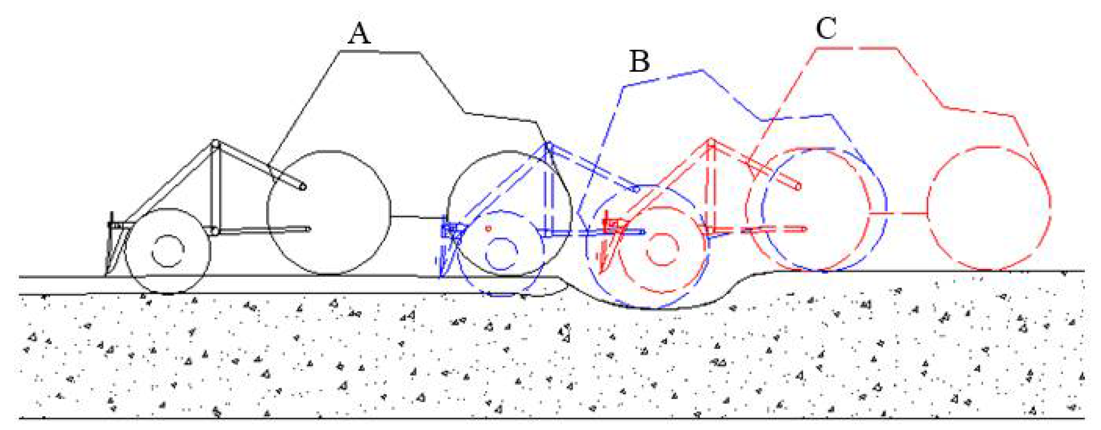
2.2. Kinematic Model of the Depth Control System

The depth control system of the rotary burying operating unit mainly relied on the four-bar mechanism of the tractor rear hitch, as shown in Figure 3. The working depth of the tiller was mainly controlled by the lift arm L of the tractor rear hitch, and the height of the lift arm L was controlled by the upper swing arm l1 through the connecting rod l2. In this study, the height of the tiller was changed by adjusting the angle of the upper swing arm l1 to realize the depth control of the rotary burying operation in real-time.
Each component of the four-bar mechanism is represented by a vector, and the mathematical motion model of the mechanism can be obtained as follows
l 2 l 3 = l 4 l 1
Convert vector Equation (1) to rectangular coordinates as follows:
{ l 4 = l 3 cos θ 3 + l 2 cos θ 2 + l 1 cos θ 1 l 1 sin θ 1 = l 2 sin θ 2 + l 3 sin θ 3
Then, the machine lifting angle θ3 can be calculated by Equation (3):
θ 3 = 2 arctan 2 l 1 l 3 sin θ 1 + ( 2 l 1 l 3 sin θ 1 ) 2 + 4 l 3 2 ( l 1 cos θ 1 l 4 ) 2 ( l 2 2 l 1 2 l 3 2 l 4 2 + 2 l 1 l 4 cos θ 1 ) 2 2 l 3 ( l 1 cos θ 1 l 4 ) ( l 2 2 l 1 2 l 3 2 l 4 2 + 2 l 1 l 4 cos θ 1 )
Then, the real-time height H1 of the tiller is obtained by:
H 1 = L sin ( θ 3 π 2 ) = L cos θ 3
In the process of the rotary burying operation, the surface unevenness and the residual stubbles in the field made the tractor tilt, which led to the deviation of GNSS positioning, as shown in Figure 4 [32]. Because the GNSS positioning antenna was placed on the right side of the tractor, the actual height from the ground can be calculated by Equation (5):
H = H 1 cos Φ

2.3. The Design of Controller

During the operation of rotary burying, an on-board computer was used to gather the height H1 and the roll angle Ф from the GNSS and calculated the real-time height change ∆H according to the initial set target of the tillage depth D. The ideal lifting angle θ to maintain the stability of the rotary burying depth was deduced through the four-link lifting model. The variable-gain single-neuron PID algorithm output the real-time lifting angle u(t) after learning and optimizing the control effects at different times. The STM32 microcontroller compared the angle u(t) of the expected lift with the angle value θ1 of the current lift measured by the angle sensor to obtain the actual final lift angle to be executed. The output signal of the STM32 microcontroller controlled the solenoid valve to change the valve port, and the hydraulic oil flowed into the lifting oil pump of the original system to control the tractor to perform corresponding action to maintain the depth under the complex changes of the ground surface. The overall structure is shown in Figure 5.
As shown in Figure 6, when the ground surface is flat during rotary burying operation (at point A), the tillage depth control system maintains the three-point hitch height; when the rear wheel reaches the uneven ground surface (at point B), the RTK-GNSS on top of the tractor records height changes; when the rear wheels reach point C, the tillage depth control system controls the electric hydraulic valve to maintain stable tillage depths of the rotary burying operation.

2.3.1. Electronic-Control Proportional Hydraulic Valve

An electronically controlled lifting system is a prerequisite for realizing the automatic control of the rotary burying depth. The improvement in the control accuracy directly affects the precision of the rotary burying depth. Therefore, the electronic-control proportional valve is one of the key parts in the rotary burying depth control system. In order to improve the depth control accuracy, an electronic-control proportional hydraulic valve (Figure 7a,b) was designed in this study, which directly acted on the lifting hydraulic cylinder of the tractor to control the lifting piston through the original oil supply port and oil return port. This method realized controlling the lifting system quickly and accurately through a microcontroller and solved the problems of cumbersome process, slow response, and low control accuracy of the original lifting system.
After the installation of the electronic hydraulic lifting system, an on-board computer sent a square wave steering signal through a CAN bus for the lifting tracking test, as shown in Figure 7c. When the hydraulic steering valve was at half speed, the lifting arm took an average of 6.46 s to complete the whole process from the lowest point to the highest point, and 16.69 s to complete the whole process from the highest point to the lowest point. When the hydraulic steering valve was at full speed, the lifting arm took an average of 2.39 s to complete the whole lifting operation and 5.71 s to complete the whole lowering operation. In this study, in order to control the angle of the lift arm precisely, adjusting the speed of the electronic proportional hydraulic valve according to the speed of the tractor could improve the adaptability of the tillage depth control system in complex conditions of the field.

2.3.2. Variable-Gain Single-Neuron PID Controller

It can be seen from Equation (5) that the rotary burying depth of the tiller is determined by the height H1 of the tiller and the roll angle Ф. In the field, the angle of the hitch system is continuously adjusted in the rotary burying operation to reduce depth error in real-time. The STM32 microcontroller of the depth control system outputs the corresponding control signal to perform the lifting operation according to the ideal angle ∆θ of the rear hitch system. However, the conventional PID controller has no self-learning and self-adaptation ability, which leads to poor control performance in complex environments. Single neuron algorithms have adaptive and self-learning capabilities. The single neuron PID controller contains a single neuron algorithm that can learn according to the changes in the environment, has strong robustness and a simple structure, and occupies a small memory [33]. This study improved the single neuron algorithm in the neural network, designing a variable-gain single-neuron PID controller to adjust the PID control parameters in real-time, which improved the accuracy and robustness of the algorithm.
The proportion, integration, and differentiation of the single neuron PID controller adopt learning rates ηP, ηI, and ηD, respectively, to realize the adjustment of different coefficients. The adaptive control structure is shown in Figure 8, where Z−1 is the control quantity of the last moment.
As shown in Figure 8, three neuron distributions x1(k), x2(k), and x3(k) were used to represent the error changes at the times of k, k − 1, and k − 2 for adaptive learning. Therefore, the calculation equation is given by:
{ x 1 ( k ) = e ( k ) x 2 ( k ) = e ( k ) e ( k 1 ) x 3 ( k ) = e ( k ) 2 e ( k 1 ) + e ( k 2 )
where e(k) is the difference between the input variable r(k) and output variable y(k) at time k, and its calculation formula is:
e ( k ) = r ( k ) y ( k )
In light of the working environment of burying stubbles in the field, the supervised Hebb learning rule [34] was used in this study, and the expression is:
ω i ( k + 1 ) = ω i ( k ) + η i e ( k ) u ( k ) x i ( k ) ( i = 1 , 2 , 3 )
where ηi is the learning speed; u(k) is the output signal of single neuron adaptive PID controller at time k; and the gain K is introduced. Then, u(k) can be calculated by
u ( k ) = u ( k 1 ) + K i = 1 3 ω i ( k ) x i ( k )
The model of the conventional PID controller [23] is as follows
u ( k ) = k p e ( k ) + k i j = 1 k e ( j ) + k d [ e ( k ) e ( k 1 ) ] = u ( k 1 ) + k i e ( k ) + k p [ e ( k ) e ( k 1 ) ] + k d [ e ( k ) 2 e ( k 1 ) + e ( k 2 ) ]
where ki is the integral control coefficient; kp is the proportional control coefficient; and kd is the differential control coefficient.
From a comparison of Equations (9) and (10), 1(k), 2(k), and 3(k) of the single neuron PID correspond to the variables ki, kp, and kd. Therefore, the adjustment of gain K and weight ω is the key to the control effect of the single neuron PID algorithm. In the single neuron PID, ω is obtained by self-adaptive learning, and the gain K is fixed. The adjustment of K is necessary after the change in the control environment, which is a cumbersome process. To solve this problem, we proposed a real-time adaptive nonlinear adjustment method of K according to the error e(k), and the equation for calculating K is
K [ | e ( k ) | ] = { K B , | e ( k ) | > B ( K B K A ) ( B A ) 2 [ e ( k ) A ] 2 + K A , A < | e ( k ) | < B K A , | e ( k ) | < A
where KB and KA are the maximum and minimum values of the gain K, and B and A are the maximum and minimum values of the error e(k). By changing the real-time error e(k), the proportional gain K of the neuron PID is changed, which makes the output control variable u(k) more adaptive.

3. Results and Discussion

3.1. MATLAB Simulation Analysis

In order to verify the performance of the variable-gain single-neuron PID, this study introduced a conventional incremental PID and a common single-neuron PID for simulation comparison. The Simulink simulation model of the lifting system is shown in Figure 9. Using the trial and error method to adjust the kp, ki and kd parameters of the conventional incremental PID, the parameters were determined as kp = 0.05, ki = 2.18, and kd = 0.01. The initial values of the weighting coefficients of the single-neuron adaptive PID were set to arbitrary equal and non-zero values, and the proportional gain K and the learning rates ηP, ηI, and ηD were obtained by experiments. First, we adjusted the proportional gain K to make the controller response faster and the overshoot smaller, and then adjusted ηP, ηI, and ηD to further reduce the adjustment time and overshoot. Through the experiment, the following parameters for the single-neuron adaptive PID controller were determined: proportional gain K = 0.12, and learning rates ηP = 0.4, ηI = 0.12, ηD = 0.4. The upper and lower limits of K of the variable-gain single-neuron PID were determined as KA = 0.09 and KB = 2.15 by the trial and error method. After fixing KA and KB, the error ranges of A = 0.01, B = 1 were determined. In order to verify the feasibility of the algorithm, an input angle deviation signal of y = 50 was set and a disturbance signal of y = 100 was added for 40~50 s, referring to the three-point hitch mechanism of the tractor. The simulation results are shown in Figure 10.
The results showed that the convergence speeds of the three control algorithms from fast to slow were variable-gain single-neuron PID (12.30 s), conventional PID (15.30 s), and single-neuron PID (22.30 s), and the overshoots from large to small were conventional PID (14.08%), single-neuron PID (9.51%), and variable-gain single-neuron PID (1.92%). Through a comprehensive analysis, it could be seen that the control algorithm with variable-gain single-neuron PID had the fastest convergence speed, smallest overshoot, and best signal tracking performance, which could meet the precision requirements of the depth control of rotary burying operation.

3.2. Field Experiment

The field experiment was performed on 23 September 2021, a sunny, breezy day, in the experimental rice field of the State Key Laboratory of Crop Genetic Improvement of Huazhong Agricultural University. The field was covered with dried stubbles after harvest of early autumn rice. The soil type of the field was a common paddy soil in the middle and lower reaches of the Yangtze River. The parameters of the experiment conditions are shown in Table 2.
According to the soil texture classification standard revised by the U.S. Department of agriculture in 1951, 43.05% of the soil taken from this field was clay, 54.04% was silt, and 2.91% was sand. The soil of this field was silty clay.
In order to ensure the quality of rotary burying, the tractor speed was set to about 0.61 m/s. Two RTK-GNSS systems were set up with a data acquisition frequency of 10 Hz. One GNSS monitored changes of the ground height in real time, providing information to control the change of depth, and the other GNSS monitored height changes of the rotary tiller in real-time. Other instruments included a TJSD-750 soil compactness tester (Zhejiang Tuopu Yunnong Technology Co. Ltd., Huzhou, China), accuracy: ±0.5‰FS, an electronic scale, tapes, rulers, etc.
In order to compare the effects of rotary burying operation under three algorithms, the field was divided into three rows for the rotary burying operation using the conventional PID, single neuron PID, and variable-gain single-neuron PID.
The experiment steps were as follows:
  • Check the status of the implement to ensure the normal operation of the electric control system and hydraulic system;
  • Set the burying depth control algorithm;
  • Set up the RTK-GNSS base station as shown in shown in Figure 11, and set the GNSS positioning coordinate origin and communication port to start the rotary burying depth control system;
  • Start the operation;
  • Record test data including height changes of the tractor and the rotary tiller; and
  • Repeat steps 2 to 5 using three different control algorithms.
The experiment site is shown in Figure 12a. To ensure the effect of the rotary burying of stubbles, the burying depth was set as 16 cm considering the large amount of residual stubbles. The field experiment effects are shown in Figure 12a.
Figure 13 shows the variations of rotary burying heights and field surface heights during the straw rotary burying operation under three different control algorithms. As shown in the figure, the black curve is the variation of tractor heights measured by the RTK-GNSS installed on it, and the red curve is the variation of the rotary tiller’s heights measured by another RTK-GNSS. Overall, the rotary tiller’s heights basically changed with the variation in field heights, and the two trends matched well. According to the conditions of surface height fluctuation, the operation area was divided into areas 1, 2, and 3. Under three control algorithms, the height changes of the rotary tiller followed the basic trend of surface height changes under the condition that the field was relatively flat (area 1 with the surface height variation around 0.02 m). Their overshoots were ranked as conventional PID > single neuron PID > variable-gain single-neuron PID. In area 2 with complex surface conditions (surface height variation around 0.10 m), their overshoots were ranked as conventional PID > single neuron PID > variable-gain single-neuron PID. In area 3 with a relatively flat surface (surface height variation around 0.02 m), their overshoots were ranked as conventional PID > single neuron PID > variable-gain single-neuron PID. Overall, the control effect of variable-gain single-neuron PID was the best, which is more suitable for the automatic control of the rotary burying of stubbles in the field.
After completion of the rotary burying operation, an experimental field block with a length of 60 m was selected to measure and calculate the quality indicators according to the standards (GB/T 24685-2009 and GB/T 5668-2017). The following indicators were calculated: tillage depth, stability coefficient of tillage depth and burying rate of stubbles, and their measuring and calculating methods are described as follows [2]:
  • Tillage depth and stability coefficient of tillage depth
In order to better reflect the depth control effect, the 40-m region in the middle where tillage depths were stable was selected for measurement, and a steel ruler was inserted into the soil to read the tillage depth. With an interval of 1 m, three points were measured in each row, and the total number of measuring points in each row was 120. The calculation formulas of tillage depth and tillage depth stability coefficient are
h = i = 1 n h i n
U = [ 1 1 h i = 1 n ( h i h ) 2 n 1 ] × 100 %
where h is tillage depth, cm; hi is tillage depth of the measuring point, cm; n is total measuring points; and U is stability coefficient of tillage depth, %.
2.
Burying rate of stubbles
When calculating the burying rate of stubbles, one point was selected randomly in each measurement area and a 1 m2 block was marked. Then, we measured the mass of all unburied stubbles in the block. The calculation formula is
M = ( 1 m h m q ) × 100 %
where mq is the mass of stubbles per unit area before tillage, g/m2; mh is the mass of unburied stubbles per unit area after tillage, g/m2; and M is the burial rate of stubbles, %.
The final measured results of rotary burying of stubbles after tillage are shown in Table 3, and the effect after tillage is shown in Figure 14. As shown in Table 3, all calculated quality indicators meet the standard requirements. The variable-gain single-neuron PID control algorithm had an average rotary burying depth of 15.49 cm, and its rotary burying depth stability coefficient was 96.09%, which was 5.85% higher than that of the conventional PID control algorithm and 4.37% higher than that of the single-neuron PID control algorithm. The burying rate of stubbles of the variable-gain single-neuron PID control algorithm was 94.74%, which was 4.38% higher than that of the conventional PID control algorithm and 3.49% higher than that of the single neuron PID control algorithm, which indicates that a relatively stable operation effect was achieved.
In this study, different control algorithms affected the effect of burying stubbles into the field. Although the robustness, accuracy, and time delay of different algorithms had different effects on the operation, the suitable algorithm could still meet the requirements of stable depth control. Based on the experimental results, it is obvious that the variable-gain single-neuron PID control algorithm was adequate for the operation requirements of the rotary burying of stubbles. The response speed of the system was improved by using the electronic-control proportional hydraulic valve and the CAN bus, so the operation effect was improved.
The proposed depth control method based on variable-gain single-neuron PID demonstrated the potential of an automatic tractor-rotary tiller stubble burying system under unmanned driving. However, there were obvious limitations in the proposed method. First, the method of obtaining surface height information based on an RTK-GNSS can only be used in areas with flat terrain, because a large terrain fluctuation will directly affect the measurement accuracy. Second, the variable-gain single-neuron PID control method is greatly affected by the tractor body vibration when the height fluctuation is small, so other interference factors need to be considered for further improvement.

4. Conclusions

(1)
To solve the problems of slow response speed and inaccurate depth control of the existing rotary burying operation unit, a depth control system based on variable-gain single-neuron PID was designed and implemented. The main instruments of the depth control system included an RTK-GNSS, an electric-control proportional hydraulic valve, an STM32 microcontroller, an on-board computer, an angle sensor, and a rotary tiller for stubble burying.
(2)
When the height of the field surface changed, the driver’s experience could not accurately control the depth of the rotary tillage operation, which increased the difficulty of the operation and affected the growth of later crops. A dual antenna RTK-GNSS was used to obtain the real-time surface height and roll angle, and the height changes at the center point of the rotary tiller during the operation. These values are then sent to the variable-gain single-neuron PID control algorithm to obtain the ideal lifting angle of the three-point hitch lifting arm. Finally, the STM32 microcontroller could change the lifting angle of the lift arm in real-time through the electronic-control proportional hydraulic valve.
(3)
Simulink simulation results showed that the variable-gain single-neuron PID could alleviate the slow convergence rate and the large overshoot of the conventional PID, improve the adaptability of the scale factor K to increase the response speed of the controller, and improve the adaptability of the rotary burying depth control system to complex field surface conditions.
(4)
Field experiment results showed that compared to the conventional PID and single-neuron PID control algorithms, the variable-gain single-neuron PID control algorithm adjusted the scale factor K in real-time, making the rotary tiller follow the real-time changes of the field surface better, enhancing the adaptability and robustness of the rotary burying depth control system. When the working speed was 0.61 m/s, the variable-gain single-neuron PID could satisfy the tillage depth requirement. The stability coefficient of the tillage depth was 96.09%, which was higher than that of the conventional PID and single-neuron PID. The straw coverage rate was 94.74%, and the overall rotary burying effect was better than those of the conventional PID and single-neuron PID. The straw rotary burying depth control system designed in this study could improve the stability of the rotary burying operation and could be used for an automatic tractor-rotary tiller stubble burying system under unmanned driving.

5. Patents

Two patents have been applied in China for a control system based on variable-gain single-neuron PID in this manuscript (Application No. CN202110878664.8 and Application No. CN202110911416.9).

Author Contributions

Conceptualization, M.Z. and J.X.; Methodology, M.Z.; Software, M.Z. and C.L.; Validation, S.Z., M.H. and Z.L.; Formal analysis, M.Z.; Investigation, G.L.; Resources, S.Z.; Data curation, J.X.; Writing—original draft preparation, M.Z.; Writing—review and editing, C.L.; Visualization, M.Z.; Supervision, C.L.; Project administration, M.Z.; Funding acquisition, J.X. All authors have read and agreed to the published version of the manuscript.

Funding

This research was funded by Research Funds for Public Welfare Industries (Agriculture) (Grant No. 201503136), National Key Research and Development Program (Grant No. 2017YFD0301303), and Fundamental Research Funds for the Central Universities (Grant No. 2662019QD001).

Institutional Review Board Statement

Not applicable.

Informed Consent Statement

Not applicable.

Data Availability Statement

The data presented in this study are available on demand from the first author at [email protected].

Acknowledgments

The authors would like to thank their schools and colleagues as well as the funding of the project. All support and assistance are sincerely appreciated.

Conflicts of Interest

The authors declare no conflict of interest.

References

  1. Malhi, S.S.; Nyborg, M.; Solberg, E.D.; Dyck, M.F.; Puurveen, D. Improving crop yield and N uptake with long-term straw retention in two contrasting soil types. Field Crop Res. 2011, 124, 378–391. [Google Scholar] [CrossRef]
  2. Zhu, Y.; Zhang, J.; Zeng, R.; Zhang, W.; Yang, Q.; Xia, J. Design and experiment of herringbone type rotary blade roller for burying stubble in paddy field and dry land. Trans. CSAM 2019, 50, 49–57. [Google Scholar]
  3. Jia, H.; Wang, L.; Li, C.; Tan, H.; Ma, C. Combined stalk–stubble breaking and mulching machine. Soil Tillage Res. 2010, 107, 42–48. [Google Scholar] [CrossRef]
  4. Zhou, H.; Zhang, J.; Zhu, Y.; Zhang, C.; Tahir, H.M.; Xia, J. Design and experiment of combined tillage machine for subsoiling and rotary burying of straw incorporated into soil. Trans. CSAE 2017, 33, 17–26. [Google Scholar]
  5. Cowell, P.A.; Herbert, P.F. The design of a variable geometry linkage to improve depth control of tractor mounted implements. J. Agric. Eng. Res. 1988, 39, 85–97. [Google Scholar] [CrossRef]
  6. Xia, J.; Zhang, G.; Xu, Q.; Huang, H.; Zhou, Y. Research on The Mechanized Technology of Rotary Tillage and Stubble-Mulch for Paddy Field under Multiple Rice Cropping System. J. Huazhong Agric. Univ. 2008, 2, 331–334. [Google Scholar]
  7. Zhang, X.; Xia, J.; Zhang, J.; He, X.; Liang, S.; Zhang, S.; Wu, H.; Wan, S. Working performance experiment of combination blade roller for straw returning in paddy field and dry land. Trans. CSAE 2016, 32, 9–15. [Google Scholar]
  8. Lee, J.; Yamazaki, M.; Oida, A.; Nakashima, H.; Shimizu, H. Electro-hydraulic tillage depth control system for rotary implements mounted on agricultural tractor design and response experiments of control system. J. Terramech. 1998, 35, 229–238. [Google Scholar] [CrossRef]
  9. Xia, J.; Li, D.; Liu, G.; Cheng, J.; Zheng, K.; Luo, C. Design and test of electro-hydraulic monitoring device for hitch tillage depth based on measurement of tractor pitch angle. Trans. CSAM 2021, 52, 386–395. [Google Scholar]
  10. Li, Q.; Luo, X.; Wang, M.; Zhao, Z.; Qu, Y.; Liu, G.; Lin, J.; Si, Y. Design of paddy field leveler using tilt sensor. Trans. CSAE 2007, 23, 88–93. [Google Scholar]
  11. Yao, D.; Liu, C. Research and design of JPD-360 dryland laser grader. J. Agric. Mech. Res. 2017, 39, 85–95. [Google Scholar]
  12. Hu, L.; Luo, X.; Lin, C.; Yang, W.; Xu, Y.; Li, Q. Development of 1PJ-4.0 laser leveler installed on a wheeled tractor for paddy field. Trans. CSAM 2014, 45, 146–151. [Google Scholar]
  13. Marucci, A.; Colantoni, A.; Zambon, I.; Egidi, G. Precision Farming in Hilly Areas: The Use of Network RTK in GNSS Technology. Agriculture 2017, 7, 60. [Google Scholar] [CrossRef] [Green Version]
  14. Heiß, A.; Paraforos, D.; Griepentrog, H. Determination of Cultivated Area, Field Boundary and Overlapping for A Plowing Operation Using ISO 11783 Communication and D-GNSS Position Data. Agriculture 2019, 9, 38. [Google Scholar] [CrossRef] [Green Version]
  15. Liu, G.; Kang, X.; Xia, Y.; Jing, Y. Global path planning method and experiment based on GNSS farmland leveling. Trans. CSAM 2018, 49, 27–33. [Google Scholar]
  16. Neményi, M.; Mesterházi, P.; Pecze, Z.; Stépán, Z. The role of gis and gps in precision farming. Comput. Electron. Agric. 2003, 39, 45–55. [Google Scholar] [CrossRef]
  17. Hobbs, J.; Hesse, H. Electronic/Hydraulic Hitch Control for Agricultural Tractors. SAE Trans. 1980, 89, 3211–3219. [Google Scholar]
  18. Dell’Acqua, R.; Dell’Orto, G.; Guagliumi, R.; Amedei, G.; Cevolini, A. Agricultural Vehicle Electronics—A New Hitch Control; SAE Technical Paper 860479; SAE International: Warrendale, PA, USA, 1986. [Google Scholar] [CrossRef]
  19. Kovacev, I.; Kosutic, S.; Jejcic, V.; Copec, K.; Pliestic, S. Impact of Electronic-Hydraulic Hitch Control on Rational Exploitation of Tractor in Ploughing. STROJARSTVO 2008, 50, 287–294. [Google Scholar]
  20. Du, Q.; Chen, X. Design on Control System for Electro-Hydraulic Hitch Equipment of Tractor. Adv. Mater. Res. 2014, 945, 1513–1516. [Google Scholar] [CrossRef]
  21. Jin, X.; Chen, K.; Zhao, Y.; Ji, J.; Jing, P. Simulation of hydraulic transplanting robot control system based on fuzzy PID controller. Measurement 2020, 164, 108023. [Google Scholar] [CrossRef]
  22. Cai, S.; Becherif, M.; Wack, M. Wireless control of automotive actuator based on PID and Fuzzy Logic. IFAC 2011, 44, 9745–9750. [Google Scholar] [CrossRef]
  23. Petrov, M.; Proychev, T.; Topalov, A. Expert PID Controller with Fuzzy Self-Tuning. IFAC 1995, 28, 367–372. [Google Scholar] [CrossRef]
  24. Chang, W.D.; Hwang, R.C.; Hsieh, J.G. A multivariable on-line adaptive PID controller using auto-tuning neurons. Eng. Appl. Artif. Intell. 2003, 16, 57–63. [Google Scholar] [CrossRef]
  25. Ladjouzi, S.; Grouni, S. PID controller parameters adjustment using a single memory neuron. J. Franklin Inst. 2020, 357, 5143–5172. [Google Scholar] [CrossRef]
  26. Zhu, S.; Zhang, C. The simulation research on PID controller of tractor electric—Hydraulic hitch system. Manuf. Inf. Eng. Chin. 2008, 37, 49–53. [Google Scholar]
  27. Anthonis, J.; Mouazen, A.M.; Saeys, W.; Ramon, H. An automatic depth control system for online measurement of spatial variation in soil compaction, part 3: Design of depth control system. Biosyst. Eng. 2004, 89, 59–67. [Google Scholar] [CrossRef]
  28. Shafaei, S.M.; Loghavi, M.; Kamgar, S. A practical effort to equip tractor-implement with fuzzy depth and draft control system. Eng. Agric. Envir. Food. 2019, 12, 191–203. [Google Scholar] [CrossRef]
  29. Han, J.; Xia, C.; Shang, G.; Gao, X. In-field experiment of electro-hydraulic tillage depth draft-position mixed control on tractor. IOP Conf. 2017, 274, 012028. [Google Scholar] [CrossRef]
  30. Xi, X. Research on Force-Position Combined Control for Tractor Hydraulic Hitch System Based on CAN Bus. Master’s Thesis, Nanjing Agricultural University, Nanjing, China, 2011. [Google Scholar]
  31. Xi, X.; Lu, Z.; Li, H.; Li, X.; Guo, B. Simulation and analysis of force-position comprehensive coefficient. J. Agric. Mech. Res. 2012, 34, 62–68. [Google Scholar]
  32. He, J.; Luo, X.; Zhang, Z.; Wang, P.; Zhu, Q. Positioning correction method for rice transplanters based on the attitude of the implement. Comput. Electron. Agric. 2020, 176, 105598. [Google Scholar] [CrossRef]
  33. Zhou, M.; Xia, J.; Zheng, K.; Du, J.; Zhang, J.; Luo, C. Development of rotary straw burying and returning navigation system based on variable-gain single-neuron PID. Trans. CSAE 2021, 37, 31–40. [Google Scholar]
  34. Ding, Y.; Xia, Z.; Peng, J. Design and experiment of the single-neuron PID navigation controller for a combine harvester. Trans. CSAE 2020, 36, 34–42. [Google Scholar]
Figure 1. Components of the tillage depth control system for the tractor-rotary tiller stubble burying system. (1) RTK-GNSS receiver antenna. (2) Electronic-control proportional hydraulic valve. (3) Angle sensor. (4) On-board computer. (5) RTK-GNSS rover station. (6) STM32 microcontroller. (7) Rotary tiller for stubble burying.
Agriculture 12 00030 g001
Figure 2. Hardware structure of the rotary burying depth control system.
Agriculture 12 00030 g002
Figure 3. Structure of tractor rear hitch. Note: l1 is the length of the upper swing arm, cm; θ1 is the angle of the upper swing arm, (°); l2 is the length of the connecting rod, cm; θ2 is the steering angle of the connecting rod, (°); l3 is the length from the lift arm shaft to the connecting arm connection point, cm; θ3 is the steering angle of the lift arm, (°); l4 is the installation distance between the lifting arm and the upper swing arm, cm; L is the length of the lift arm.
Agriculture 12 00030 g003
Figure 4. Height offset during operation. (a) Operation site; (b) Schematic of height offset. Note: H1 is the height of the positioning antenna from the field surface, m; Ф is the roll angle of the GNSS heading antenna, (°); H is the actual height from the surface, m.
Agriculture 12 00030 g004
Figure 5. Overall structure of controller. Note: u(t) is the executed angle output by the variable-gain single-neuron PID controller, (°); θ1 is the current steering angle measured by the angle sensor, (°); ∆θ is the actual required angle, (°).
Agriculture 12 00030 g005
Figure 6. Schematic of rotary burying depth control. Note: point A is a flat area of the field, point B is the uneven area where the rear wheel reaches, and point C is the uneven where the rotary tiller reaches.
Agriculture 12 00030 g006
Figure 7. Electronic-control hydraulic lifting system and its lifting tracking tests. (a) Schematic of solenoid valve steering; (b) Picture of the solenoid valve; (c) Results of lifting tracking test. Note: (1) Tank. (2) Filter. (3) Hydraulic pump. (4) Externally controlled relief valve. (5) Spring check valve. (6) Electronically controlled hydraulic steering valve. (7) Hydraulic cylinder.
Agriculture 12 00030 g007
Figure 8. Structure of the single neuron adaptive PID. Note: k is the current time; r(k) is the input variable of the controller at time k; y(k) is the output variable of the controller at time k; x1(k) is the neuron recording the change of error at time k; x2(k) is the neuron recording the change of error at time k − 1; x3(k) is the neuron recording the change of error at time k − 2; ω1(k) is the learning rule of neuron x1(k); ω2(k) is the learning rule of neuron x2(k); ω3(k) is the learning rule of neuron x3(k); K is the proportional coefficient of the neuron adaptive PID; u(k) is the output signal of the single-neuron adaptive PID controller at time k.
Agriculture 12 00030 g008
Figure 9. Simulink simulation model of the lifting system.
Agriculture 12 00030 g009
Figure 10. Comparison of simulations of lifting signal tracking under different control algorithms.
Agriculture 12 00030 g010
Figure 11. Setup of the RTK-GNSS base stations.
Agriculture 12 00030 g011
Figure 12. Field experiment effects. (a) Operation site of rotary burying of stubbles; (b) The control effect of rotating burying depth using variable-gain single-neuron PID.
Agriculture 12 00030 g012
Figure 13. Effects of rotary burying heights following surface changes under three algorithms. (a) Results of conventional PID control; (b) Results of single neuron PID; (c) Results of variable-gain single-neuron PID. Note: area 1 is a flat area at the head of the field, area 2 is an area with surface unevenness in the field, and area 3 is a flat area at the end of the field.
Agriculture 12 00030 g013
Figure 14. Measuring of operation quality. (a) measuring of tillage depth; (b) measuring the amount of stubbles before tillage; (c) measuring the amount of stubbles after tillage.
Agriculture 12 00030 g014
Table 1. The main structural parameters of a herringbone type rotary tiller.
ParametersValues
Overall dimensions/(mm × mm × mm)1345 × 2500 × 1300
Overall weight/kg750
Working width/mm2300
Rotary burying depth/mm120~180
Matching power/kW≥65
Rotary knives54
Helical cross knives18
Machetes36
Table 2. Parameters of the field experiment conditions.
IndexValue
Stubble height/cm58
Stubble coverage/g.m−21273
Soil firmness/kPa1528
Soil moisture content/%36.40
Particle size distribution/%(0, 0.002] mm42.03
(0.002, 0.05] mm55.06
(0.05, 2] mm2.91
Table 3. Results of rotary burying of stubbles under three control algorithms in the field experiments.
AlgorithmAverage Depth of Rotary Burying/cmStability Coefficient of Rotary Burying Depth/%Burying Rate of Stubble/%
Conventional PID15.0590.2490.36
Single neuron PID15.2391.7291.25
Variable-gain single-neuron PID15.4996.0994.74
Note: The average depth and the stability coefficient were calculated from the data of 120 sampling points.
Publisher’s Note: MDPI stays neutral with regard to jurisdictional claims in published maps and institutional affiliations.

