


Design of an Air Suction Wheel-Hole Single Seed Drill for a Wheat Plot Dibbler
 and
and
Abstract
:1. Introduction
2. Materials and Methods
2.1. Overall Structure and Working Principle
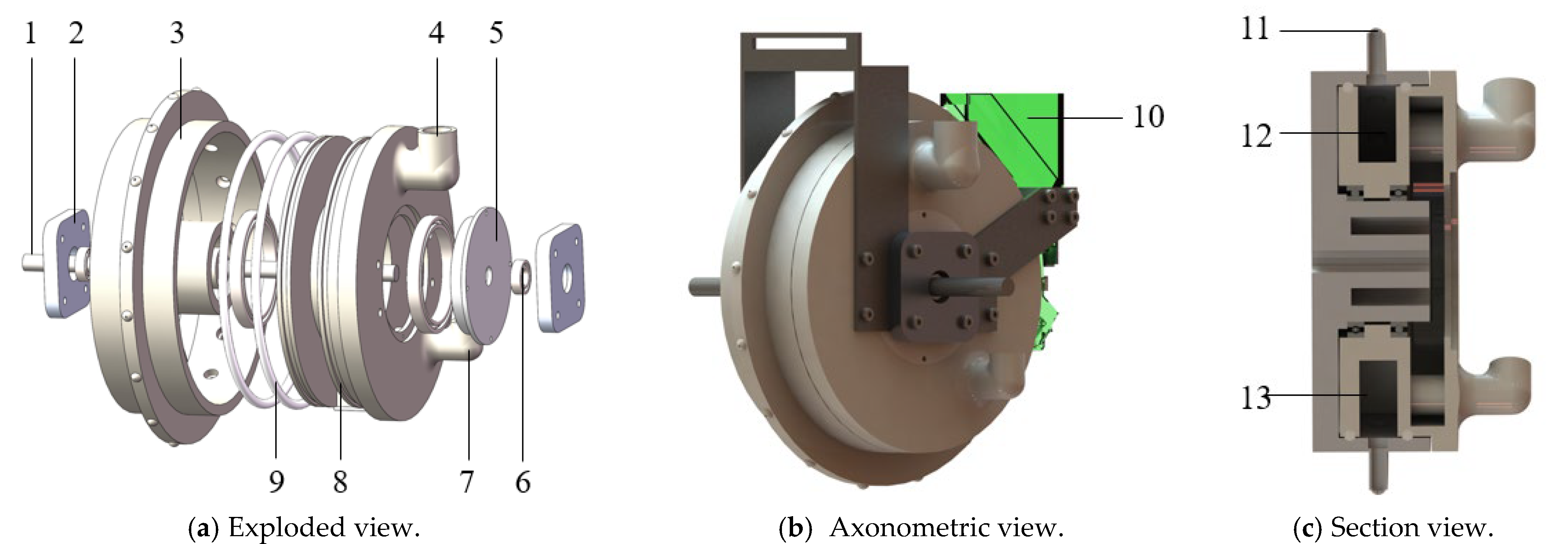
2.1.1. Integral Structure of the Air Suction Wheel-Hole Single Seed Drill

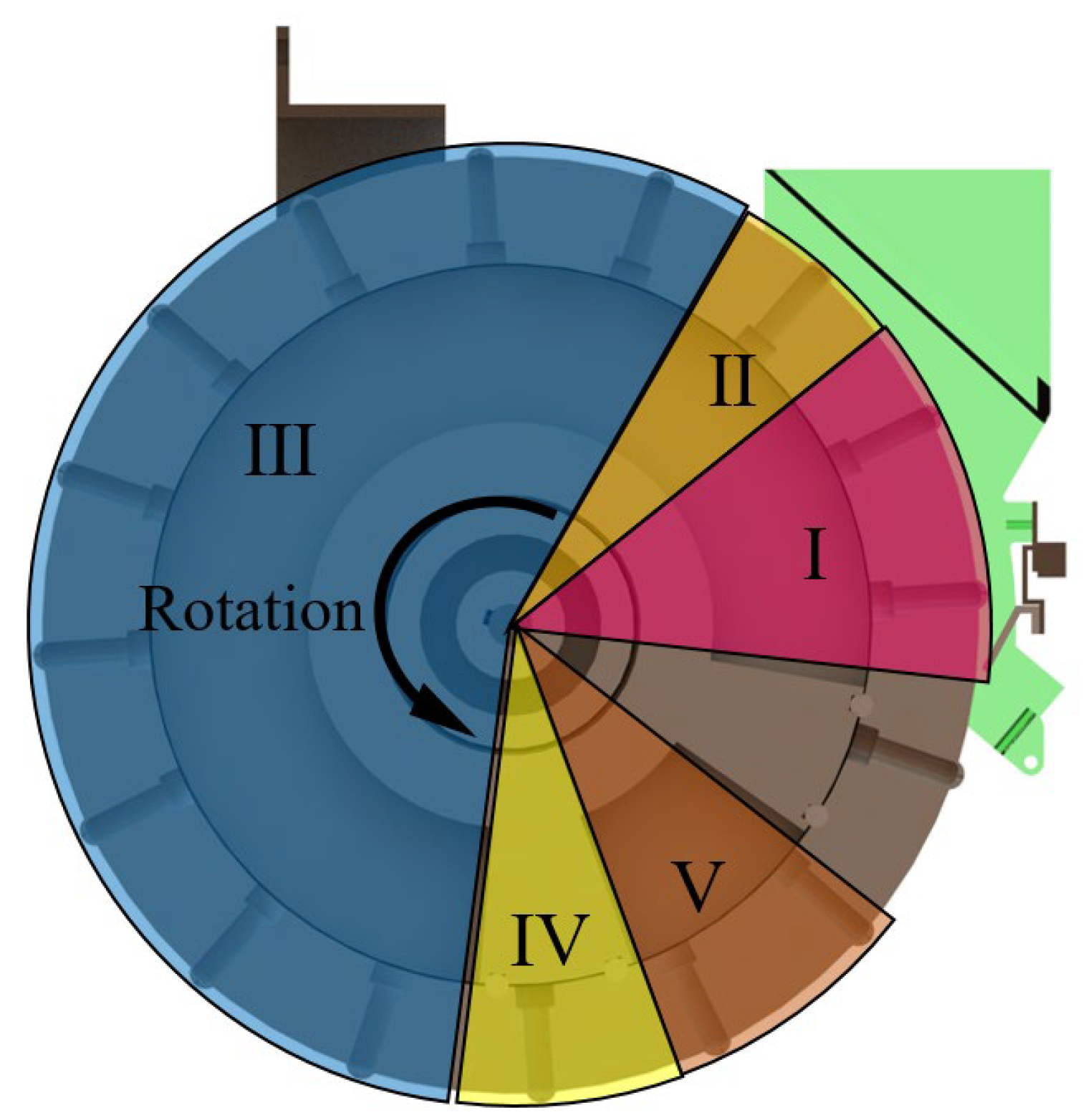
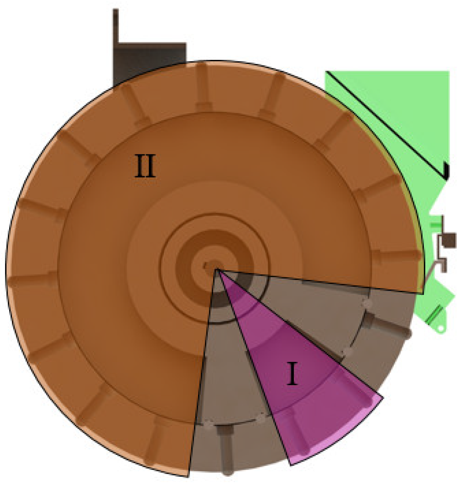
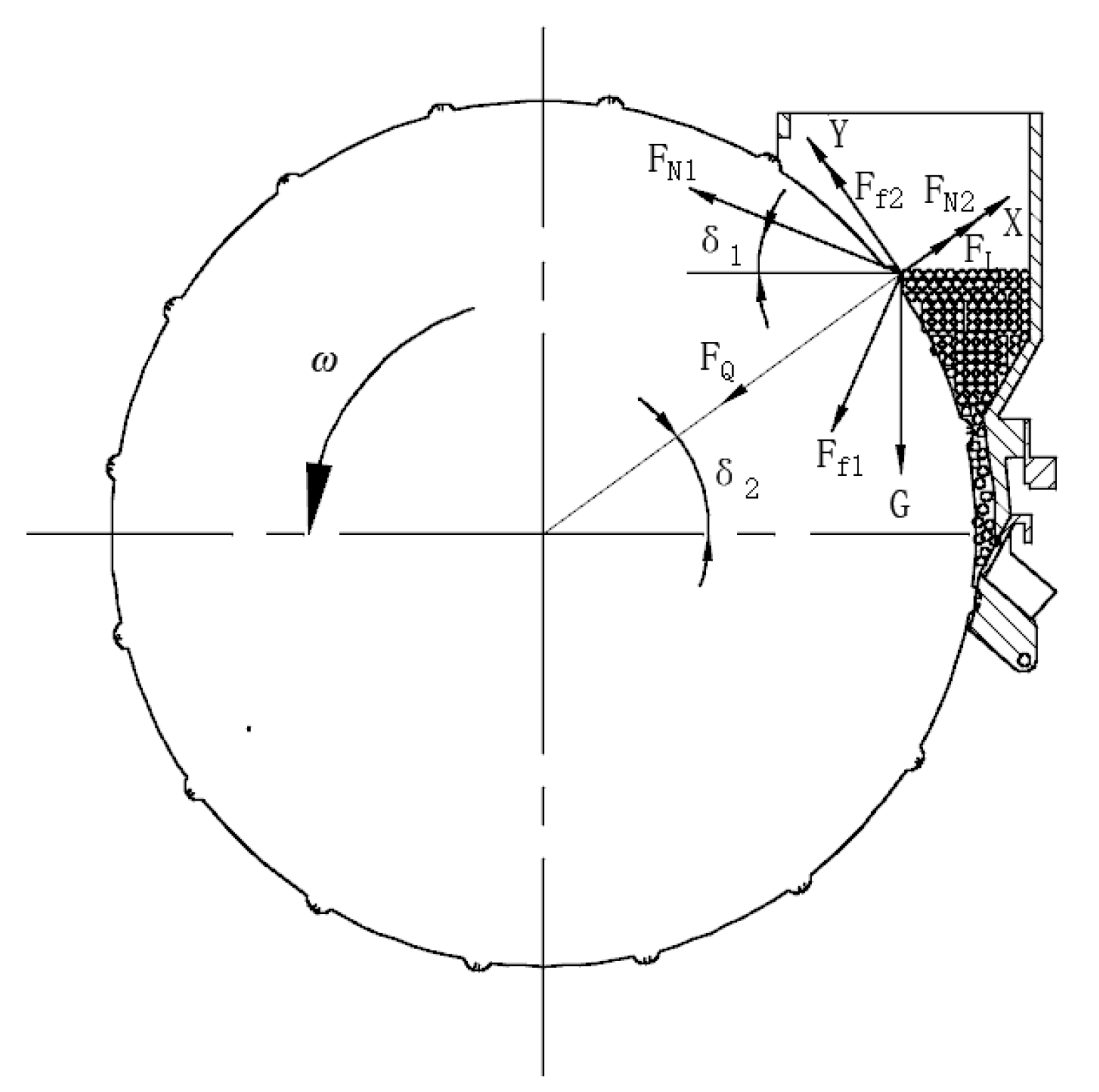
2.1.2. Working Principle
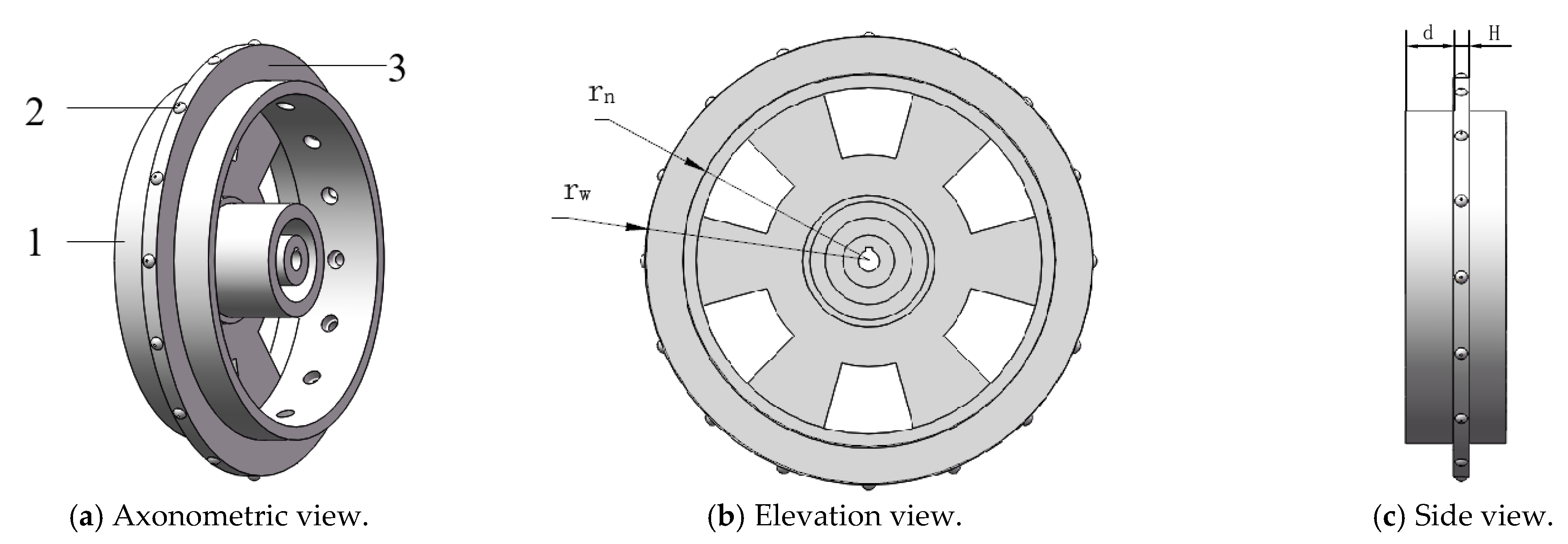
2.2. Design of Relevant Parameters of the Seed Metering Wheel
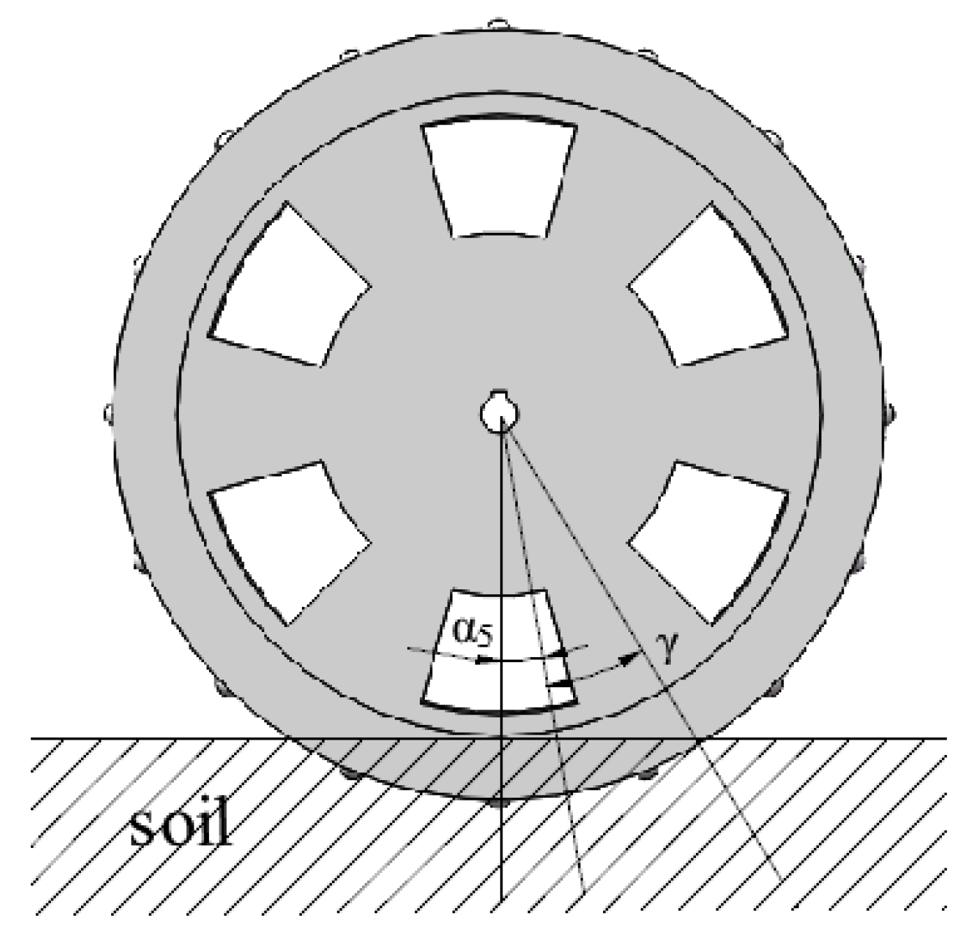
2.2.1. Design of the Number of Seed Suction Holes
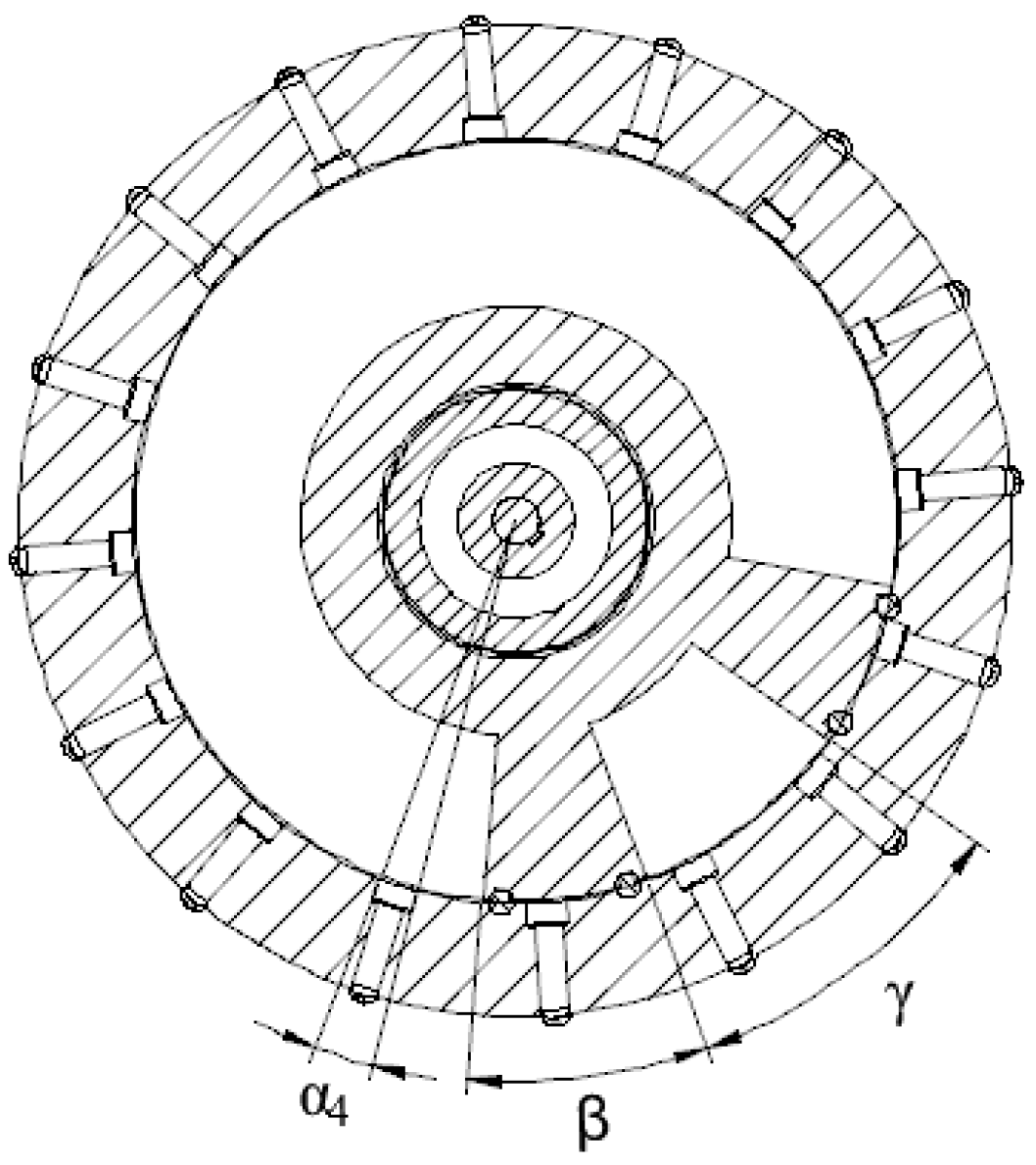
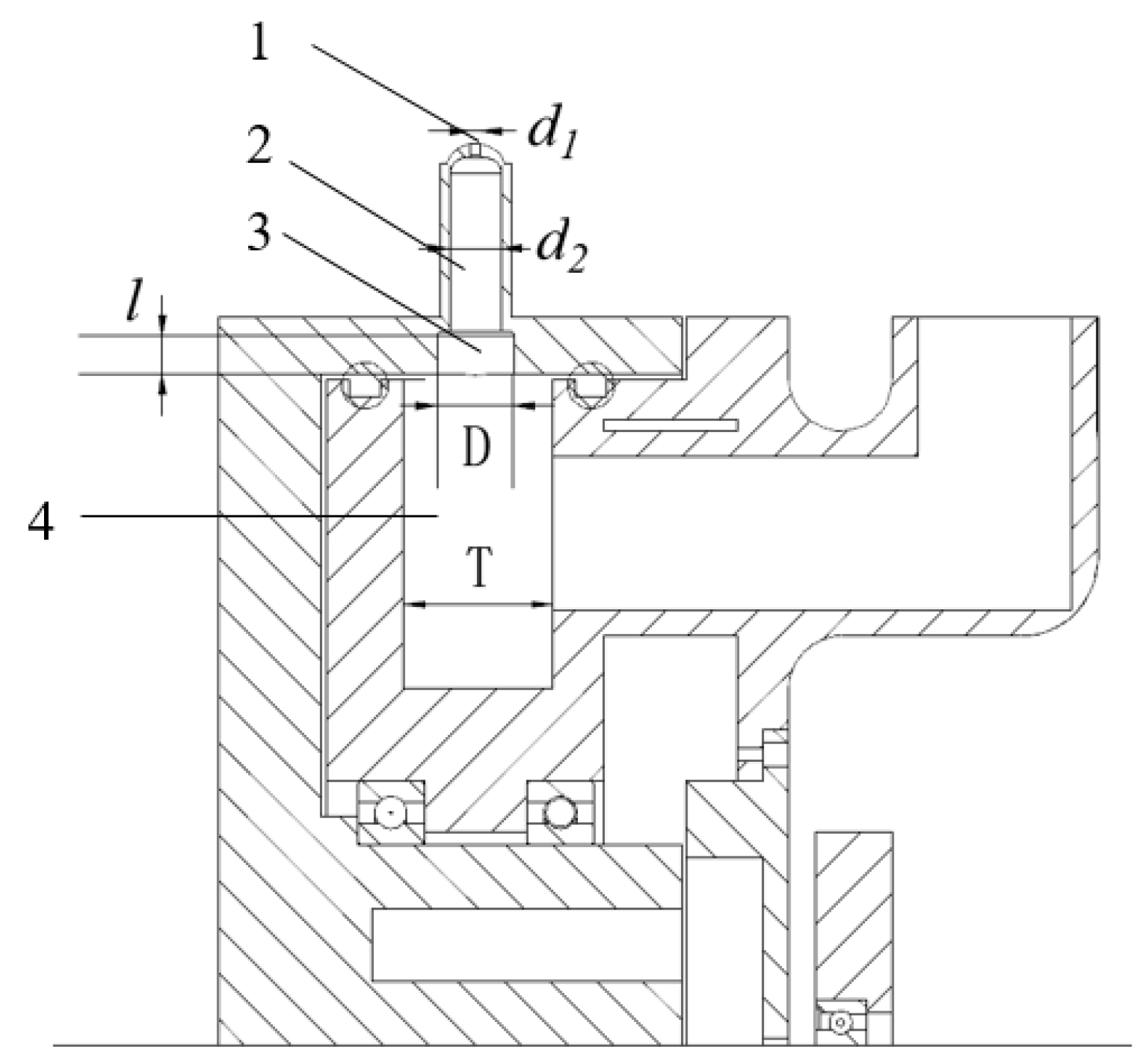
2.2.2. Parameter Design of Seed Suction Bump
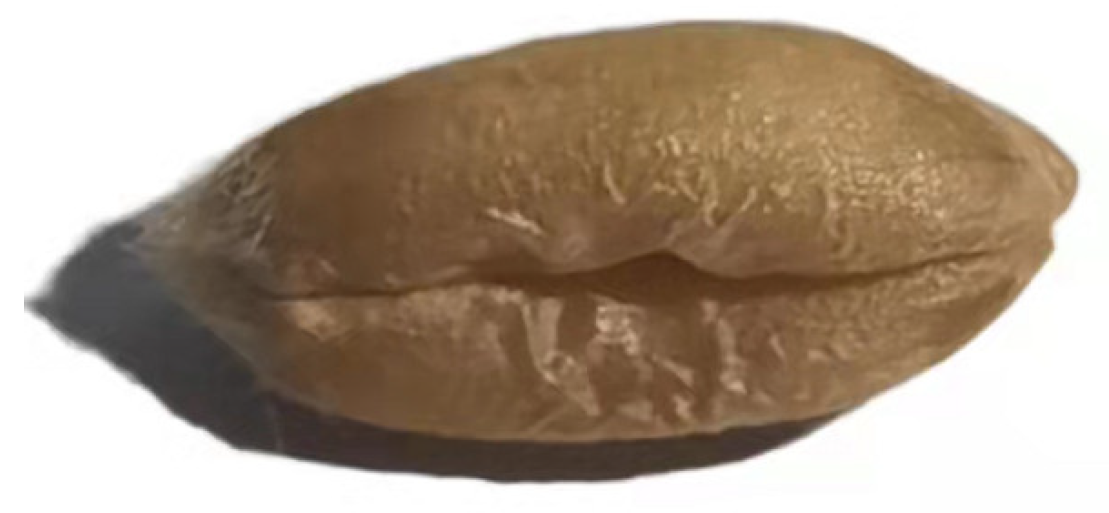
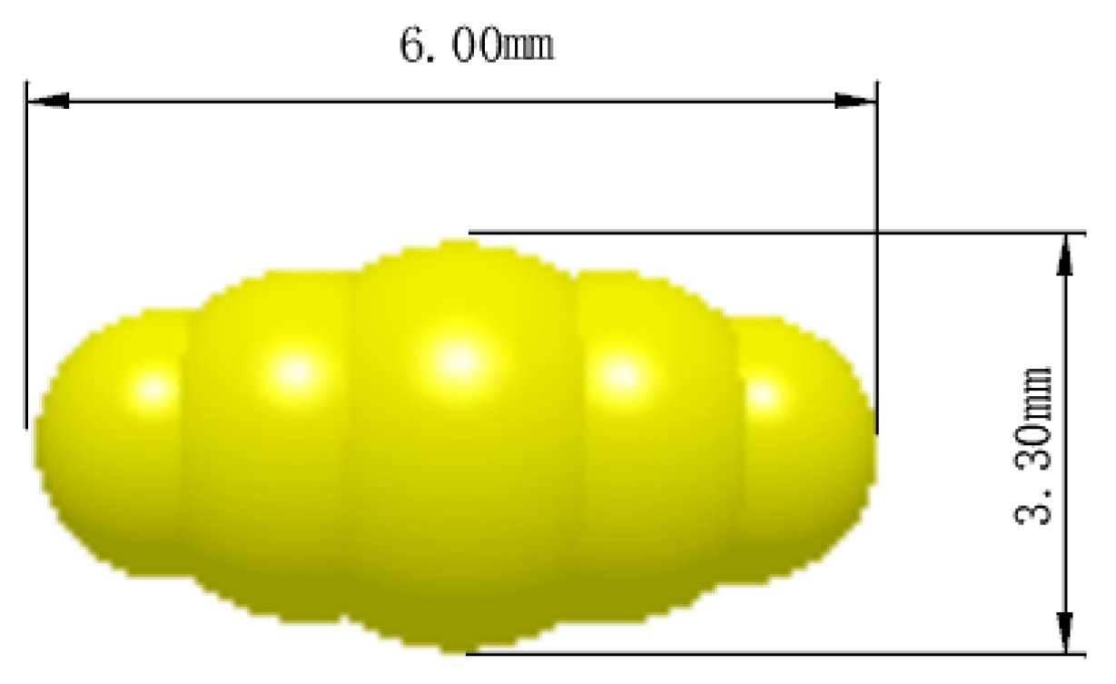
2.2.3. Determination of Wheat Seed Parameters
2.3. Design of Relevant Parameters of the Seed Metering Wheel
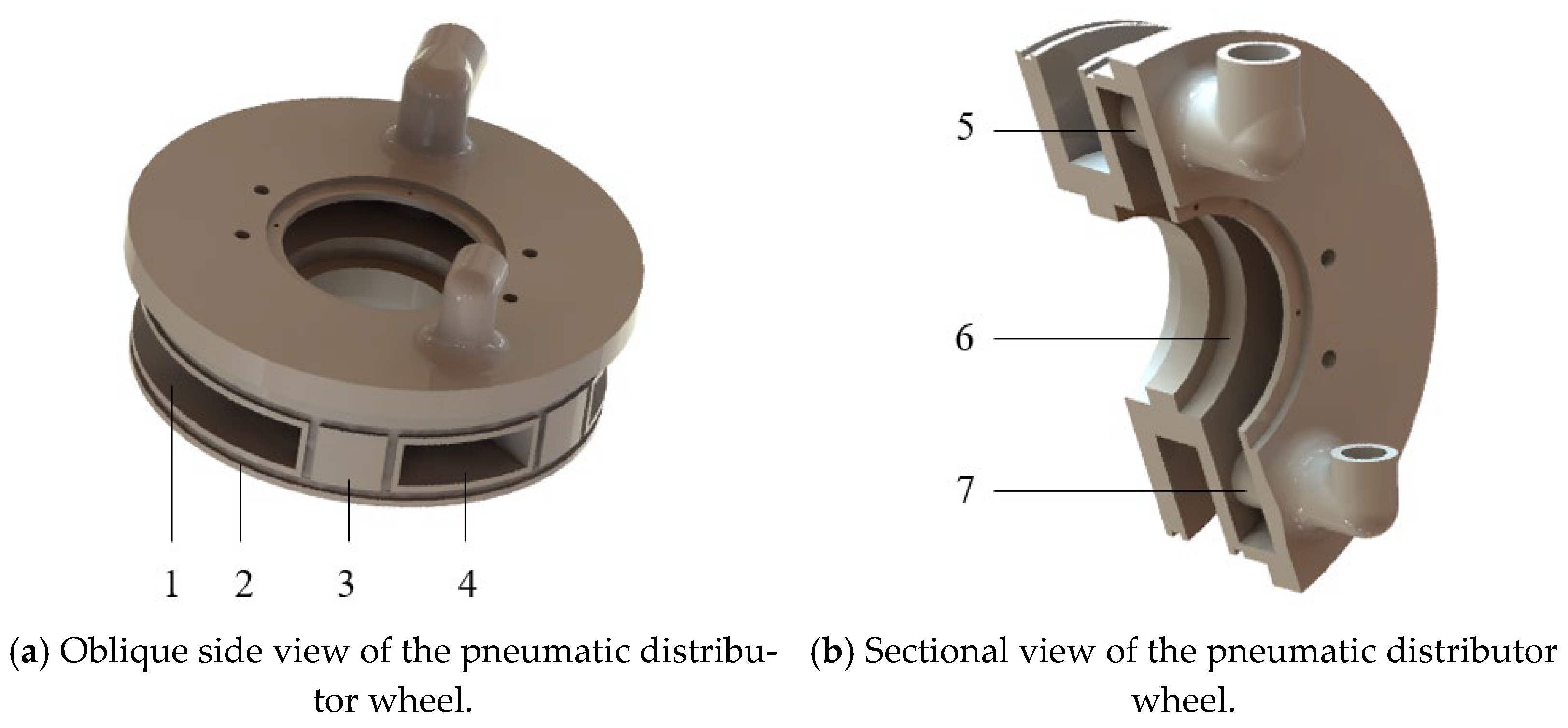
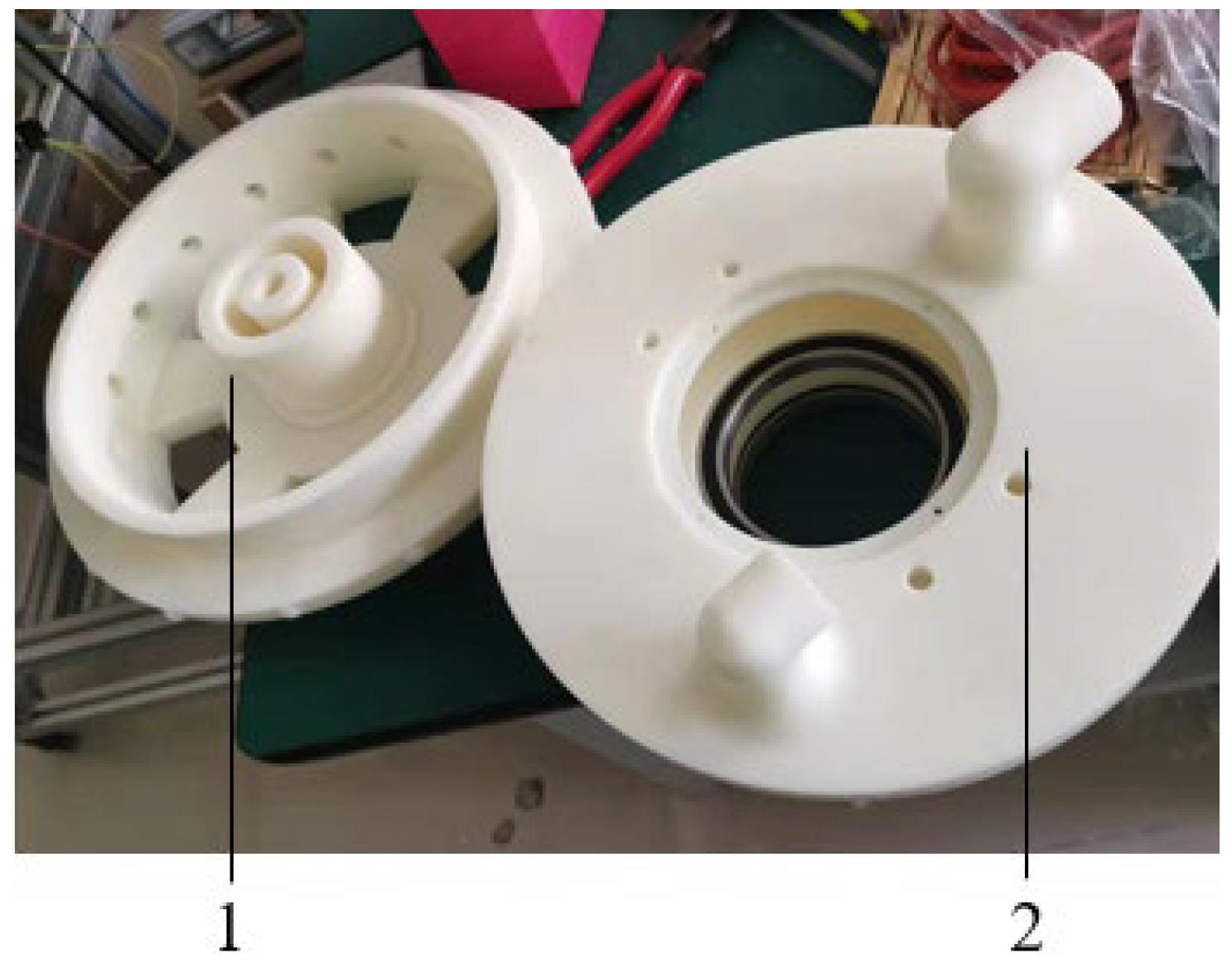
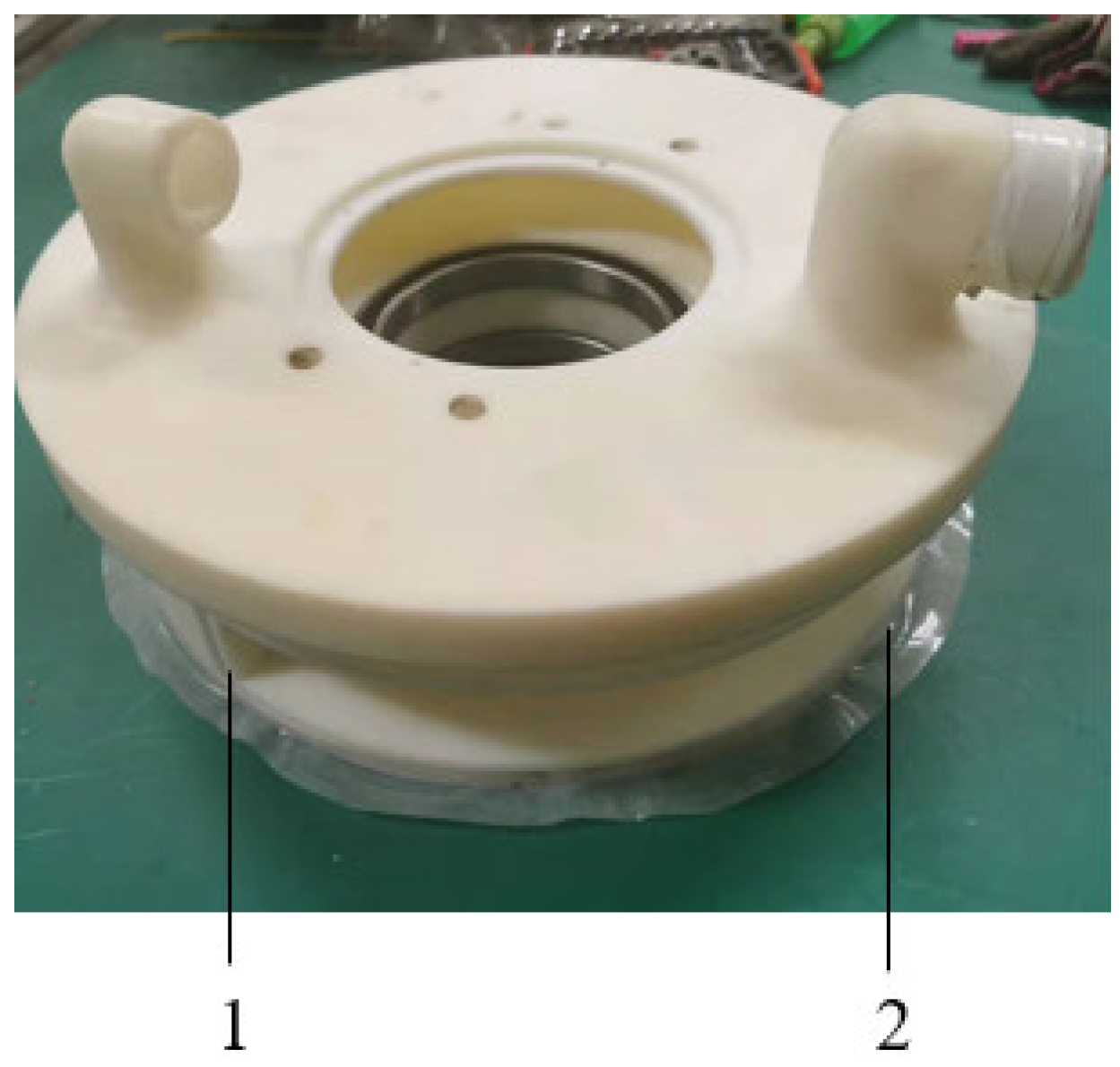
2.3.1. Overall Structural Design of the Pneumatic Distribution Wheel

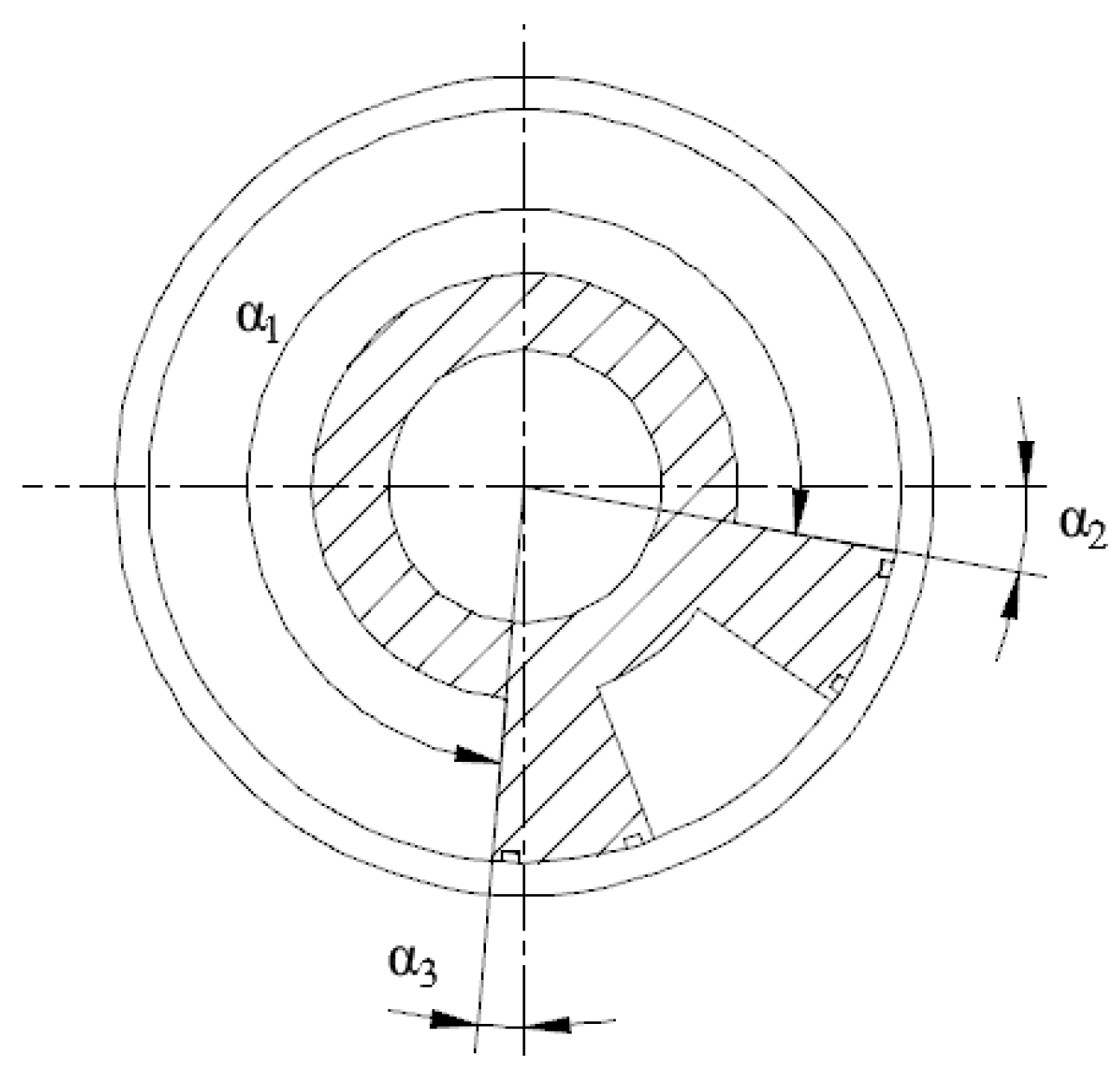
2.3.2. Parameter Design of the Air Chamber of the Seed Drill

3. Results and Analysis
3.1. Simulation Analysis of the Seed Drill
3.1.1. Selection of the Simulation Analysis Parameters
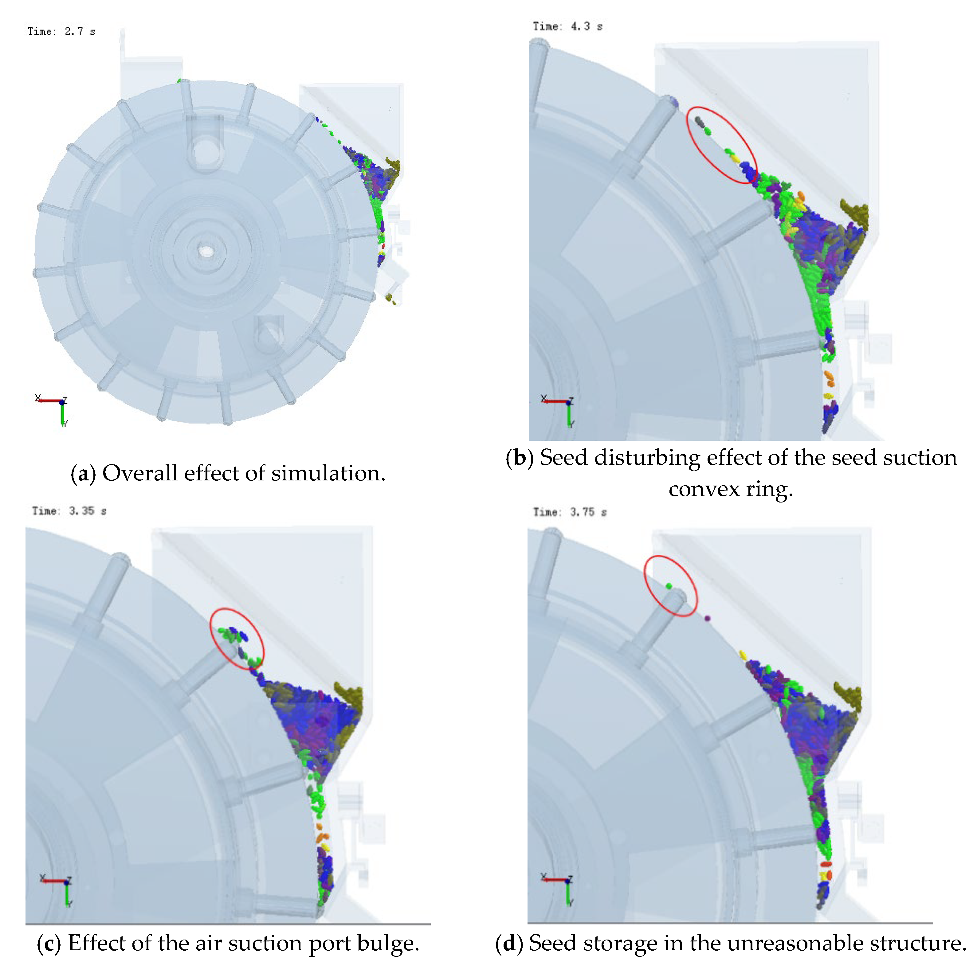
3.1.2. Simulation Results
3.1.3. Analysis of the Simulation Data
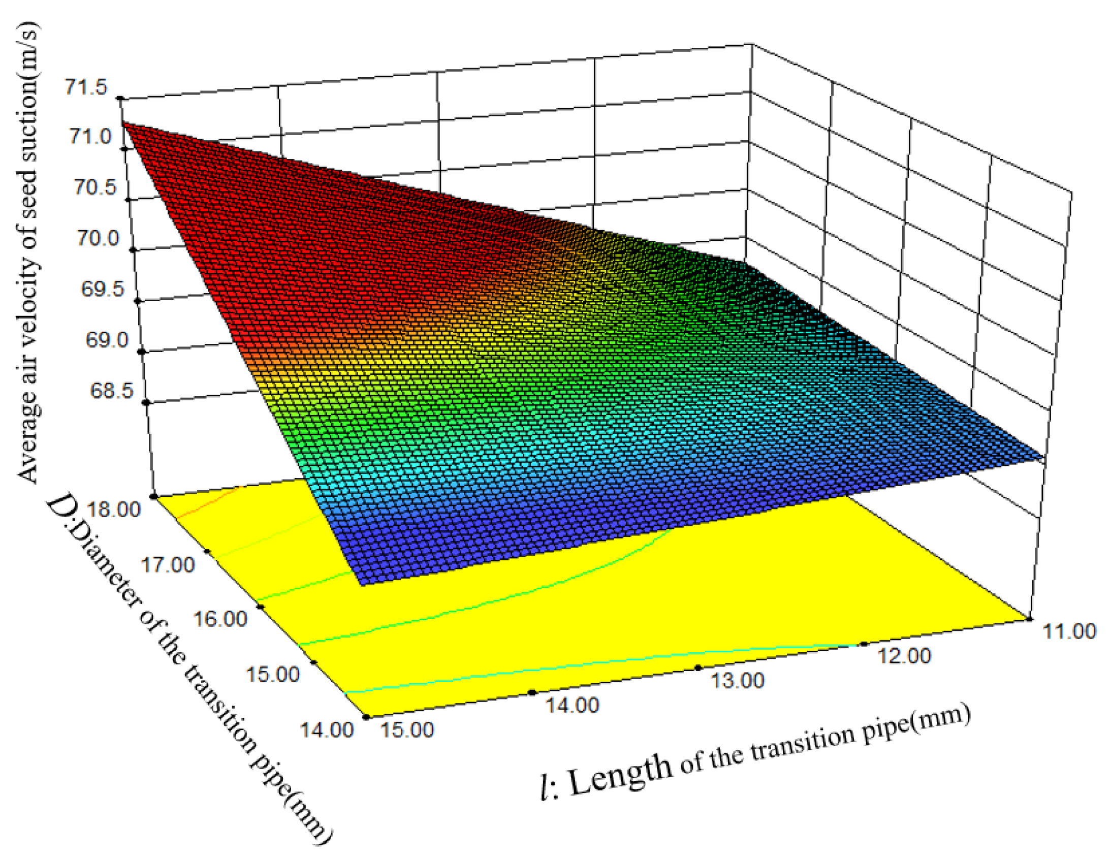
3.2. Simulation Analysis of the Air Chamber
3.2.1. Selection of the Simulation Analysis Parameters
3.2.2. The Simulation Results
3.2.3. Analysis of the Simulation Data
3.3. Benchtop Experiment Verification of the Seed Drill
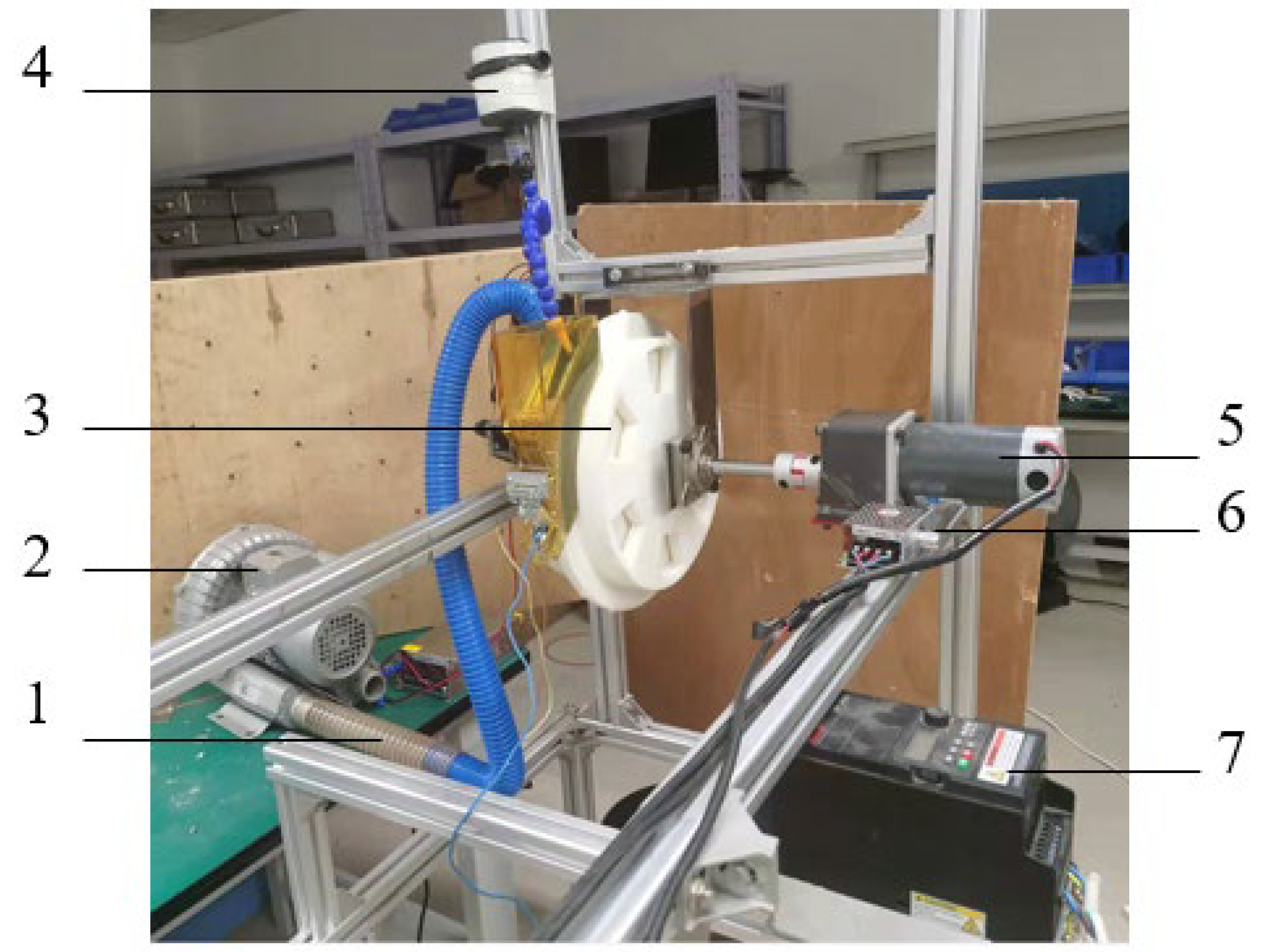
3.3.1. Experiment Conditions
3.3.2. Experiment Methods and Results
4. Conclusions
Author Contributions
Funding
Institutional Review Board Statement
Data Availability Statement
Conflicts of Interest
References
- Zhao, G.; Chang, X.; Wang, D.; Yang, Y.; Feng, J. Research Report on Development of China’s Wheat Production Potential. Crops 2012, 16, 1–5. [Google Scholar] [CrossRef]
- Sown Area of Main Crops. National Bureau of Statistics. Available online: https://data.stats.gov.cn/easyquery.htm?cn=C01 (accessed on 20 March 2022).
- Yao, W. Research and Design of Key Technology andt7 Components pf Wheat for Breeding Pots Harvester. Master’s Thesis, Shandong Agricultural University, Tai’an, China, 2017. Available online: https://kns.cnki.net/KCMS/detail/detail.aspx?dbname=CMFD201801&filename=1017062959.nhC01 (accessed on 20 March 2022).
- Lian, Z.; Wang, J.; Yang, Z.; Shang, S. Development of plot-drilling mechanization in China. Trans. Chin. Soc. Agric. Eng. 2012, 28, 140–145. [Google Scholar] [CrossRef]
- Liu, S.; Li, Y. Research on Plot Mini Precision Seeder. J. Agric. Mech. Res. 2013, 35, 81–84+88. [Google Scholar] [CrossRef]
- Parish, R.L.; Bracy, R.P. An Attempt to Improve Uniformity of a Gaspardo Precision Seeder. Hort Technol. 2003, 13, 100–103. Available online: https://xueshu.baidu.com/usercenter/paper/show?paperid=a1692c4e4dd073822918576f00a2ee2e&site=xueshu_senhC01 (accessed on 21 March 2022). [CrossRef] [Green Version]
- Shang, S.; Wu, X.; Yang, R. Research Status and Prospect of Plot-sowing Equipment and Technology. Trans. Chin. Soc. Agric. Mach. 2021, 52, 2. [Google Scholar] [CrossRef]
- Guo, P.; Shang, S.; Wang, Y. Popularize and Improve the Level of Mechanization Field Breeding Equipment. Trans. Chin. Soc. Agric. Eng. 2003, z1. Available online: https://d.wanfangdata.com.cn/conference/5800422 (accessed on 21 March 2022).
- Liu, J.X. Research on Technology and Device for Pneumatic Pinhole-Wheel Precise Point-Seeding on Wheat Plot [D]; China Agricultural University: Beijing, China, 2020. [Google Scholar]
- Yang, W.; Wang, F.; He, Z.; Li, J.; Yang, C. Development Present Situation and Prospect of Plot Breeding Machinery. Agric. Eng. 2014, 4, 7–9+56. Available online: https://www.doc88.com/p-4911544946322.html (accessed on 21 March 2022).
- Yang, B.; Wang, W.; Li, T.; Ma, X.; Yan, S. Design of Precision Seeder for Cotton Plot in Xinjiang. J. Agric. Mech. Res. 2019, 5, 65–70. Available online: http://www.cqvip.com/QK/97903X/20195/7001292377.html (accessed on 23 March 2022).
- Engel, R.E.; Fischer, T.; Miller, J.; Jackson, G. A Small-Plot Seeder and Fertilizer Applicator. Agron. J. 2003, 95, 1337–1341. Available online: https://www.zhangqiaokeyan.com/academic-journal-foreign_other_thesis/020413456469.html (accessed on 23 March 2022). [CrossRef]
- Cong, J.; Liao, Q.; Cao, X.; Liao, Y.; Yu, J.; Wang, L. Seed Filling Performance of Dual-purpose Seed Plate in Metering Device for Both Rapeseed & Wheat Seed. Trans. Chin. Soc. Agric. Eng. 2014, 30, 30–39. [Google Scholar] [CrossRef]
- Benjamin, E.; Krishnan, D.A.; Kavitha, R. Optimization of Parameters for the Development of Precision Metering Mechanism for Application of Granular Urea. Trends Biosci. 2015, 8, 6849–6853. Available online: https://www.researchgate.net/publication/326697824 (accessed on 23 March 2022).
- Yang, L.; Yang, B.; Zhang, D.; Zhang, T.; Wang, Y.; Cui, T. Research Progress on Precision Planting Technology of Maize. Trans. Chin. Soc. Agric. Mach. 2016, 47, 11. [Google Scholar] [CrossRef]
- Yang, H. Improvement of Ploy Seeder based on Cone Canvas Seed Metering Device and Design of Electric Control System. Master’s Thesis, Chengdu University, Chengdu, China, 2020. Available online: https://kns.cnki.net/KCMS/detail/detail.aspx?dbname=CMFD202002&filename=1020975124.nh (accessed on 23 March 2022).
- Liu, S.; Shang, S.; Yang, R.; Zheng, Y.; Zhao, J. Analysis of Plot Seeder Development. J. Agric. Mech. Res. 2011, 33, 237–241. [Google Scholar] [CrossRef]
- Song, J.; Zhang, S. Current Situation and Developmental Orientation of Plot Seeder. J. Agric. Mech. Res. 2004, 4, 14–16. Available online: https://kns.cnki.net/kcms/detail/detail.aspx?FileName=NJYJ200404007&DbName=CJFQ2004 (accessed on 23 March 2022).
- Lu, B.; Lu, Z.; Zhang, Z. Research Progress on Mechanization of Crop Breeding Experimental Area. Chin. Agric. Mech. 2006, 6, 44–47. Available online: https://kns.cnki.net/kcms/detail/detail.aspx?FileName=GLJH200606015&DbName=CJFQ2006 (accessed on 24 March 2022).
- Wintersteiger. Wintersteiger AG History. 2010-04-02. Available online: http://www.wintersteiger.com (accessed on 24 March 2022).
- Huo, W.; Lv, Z. Development and Research Status of Pneumatic Precision Seeder. Farm Mach. 2003, 4, 50–51. Available online: https://kns.cnki.net/kcms/detail/detail.aspx?FileName=NYJI200304018&DbName=CJFQ2003 (accessed on 25 March 2022).
- Zhang, H.; Han, Z.; Wang, L. Present Researching Status and Development of Pot Seed Harvesting Machinery. Hunan Agric. Sci. 2008, 6, 102–104+139. [Google Scholar] [CrossRef]
- Wintersteiger, A.G. Plot Seeders[M]; Wintersteiger AG: Ried Innkreis, Austria, 2009; pp. 4–21. [Google Scholar]
- Yang, W.; Li, J.; Fang, X.; Shang, S.; Du, W. Domestic and Foreign Current Situation and Development Trend of Seeding Mechanization in Maize Breeding. Agric. Eng. 2018, 8, 9–15. [Google Scholar] [CrossRef]
- Wang, C. Development of Mechanization of Field Breeding Experiment. World Agric. 2001, 4, 43–44. [Google Scholar] [CrossRef]
- The First Oyjord Plot Seeder. Available online: https://www.oyjord.org/2017/08/29/the-first-oyjord-plot-seeder/ (accessed on 26 March 2022).
- Shang, S.; Yang, R.; Yin, Y.; Guo, P.; Sun, Q. Current Situation and Development Trend of Mechanization of Field Experiments. Trans. Chin. Soc. Agric. Eng. 2010, 26, 5–8. [Google Scholar] [CrossRef]
- Tang, H. Design and Mechanism Analysis of Ripple Surface Pickup Finger Maize Precision Seed Metering Device. Ph.D. Thesis, Northeast Agricultural University, Harbin, China, 2018. Available online: https://kns.cnki.net/KCMS/detail/detail.aspx?dbname=CDFDLAST2019&filename=1019012157.nh (accessed on 26 March 2022).
- Zhang, H.; Zhao, J.; Hu, G.; Bo, L.; Wang, Z.; Qi, C.; Han, B.; Chen, J. Parameter Optimization of Wheat Seeding Device with Nest Round Wheel. J. Agric. Mech. Res. 2020, 42, 139–144. [Google Scholar] [CrossRef]
- Yang, W.; Fang, X.; Li, J.; Li, L. Design and Experiment of Air-suction Precision Seed Meter with Self-clearing Seed Chamber for Corn Plot Test. Trans. Chin. Soc. Agric. Mach. 2019, 50, 64–73. [Google Scholar] [CrossRef]
- Diao, H.; Zhang, Y.; Diao, P.; Zhao, N. Design and Experiment of a No-tillage and Wide Band Wheat Planter with Subsoilers Based on EDEM. J. Agric. Mech. Res. 2017, 39, 58–62. [Google Scholar] [CrossRef]
- Deng, L.; Qiao, T. Design and Experiment of Wheat Precision Metering Device Based on EDEM. J. Agric. Mech. Res. 2021, 43, 158–163. [Google Scholar] [CrossRef]
- GB/T 6973-2005; Experiment Method for Single Grain (Precision) Seeders. Ministry of Industry and Information Technology of the People’s Republic of China: Beijing, China, 2005.
- GB/T 10293-2013; Technical Conditions for Single Grain (Precision) Seeders. Ministry of Industry and Information Technology of the People’s Republic of China: Beijing, China, 2013.


| Parameters | Maximum | Minimum | Standard Deviation | Average Value |
|---|---|---|---|---|
| Length | 7.42 | 5.64 | 0.63 | 6.05 |
| Width | 4.10 | 2.53 | 0.47 | 3.32 |
| Thickness | 3.82 | 2.86 | 0.35 | 3.15 |
| Equivalent diameter | 4.43 | 3.44 | 0.36 | 3.88 |
| Factors | Parameters | Value |
|---|---|---|
| Wheat seed properties | Poisson’s ratio | 0.35 |
| Young’s modulus/MPa | 275 | |
| Density/(g/cm3) | 1.68 | |
| Seed metering wheel attribute | Poisson’s ratio | 0.44 |
| Young’s modulus/MPa | 2590 | |
| Density/(g/cm3) | 1.16 | |
| Seed box properties | Poisson’s ratio | 0.25 |
| Young’s modulus/MPa | 2170 | |
| Density/(g/cm3) | 2.85 | |
| Wheat seeds-wheat seeds | Impact recovery coefficient | 0.168 |
| Static friction coefficient | 0.652 | |
| Dynamic friction coefficient | 0.076 | |
| Wheat seeds– seed metering wheel | Impact recovery coefficient | 0.424 |
| Static friction coefficient | 0.586 | |
| Dynamic friction coefficient | 0.072 | |
| Wheat seeds-seed box | Impact recovery coefficient | 0.710 |
| Static friction coefficient | 0.614 | |
| Dynamic friction coefficient | 0.070 |
| Level Codes | Factors | ||
|---|---|---|---|
| Thickness of Seed Suction Convex Ring/H (mm) | Bulge Height of Seed Suction Mouth/h (mm) | Coefficient/ki | |
| 1 | 12 | 3 | 0.55 |
| 2 | 14 | 4.5 | 0.65 |
| 3 | 16 | 6 | 0.75 |
| Experiment No. | Experiment Factor and Level | Average Velocity of Seed Group (m/s) | ||
|---|---|---|---|---|
| H | h | ki | ||
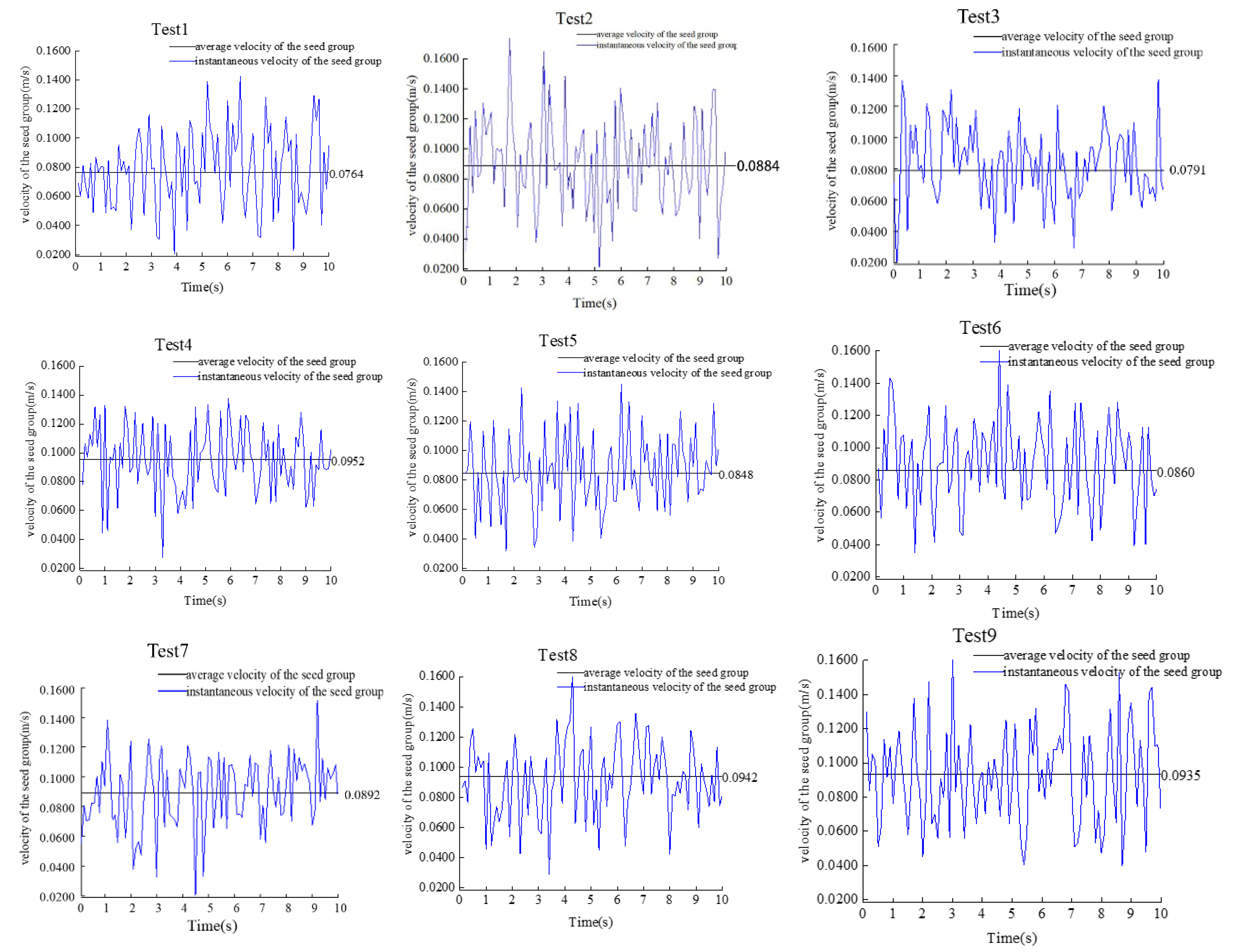
| 1 | 1 | 1 | 1 | 0.0764 |
| 2 | 1 | 2 | 3 | 0.0848 |
| 3 | 1 | 3 | 2 | 0.0791 |
| 4 | 2 | 1 | 3 | 0.0952 |
| 5 | 2 | 2 | 2 | 0.0848 |
| 6 | 2 | 3 | 1 | 0.0860 |
| 7 | 3 | 1 | 2 | 0.0892 |
| 8 | 3 | 2 | 1 | 0.0942 |
| 9 | 3 | 3 | 3 | 0.0935 |
| Analysis Factors | Average Velocity of Seed Group (m/s) | ||
|---|---|---|---|
| H | h | ki | |
| k1 | 0.0801 | 0.0869 | 0.0855 |
| k2 | 0.0887 | 0.0879 | 0.0844 |
| k3 | 0.0923 | 0.0862 | 0.0912 |
| The optimal array | H3h2ki3 | ||
| Level Codes | Factors | ||
|---|---|---|---|
| Thickness of Negative Pressure Chamber/T (mm) | Diameter of Transition Pipe /D (mm) | Length of Transition Pipe /l (mm) | |
| 1 | 22 | 14 | 11 |
| 2 | 24 | 16 | 13 |
| 3 | 26 | 18 | 15 |
| Experiment No. | Experiment Factors and Levels | Average Air Velocity of Seed Suction Hole/Y (m/s) | ||
|---|---|---|---|---|
| T | D | l | ||
| 1 | 3 | 2 | 3 | 71.32 |
| 2 | 2 | 2 | 2 | 70.02 |
| 3 | 3 | 3 | 2 | 70.96 |
| 4 | 1 | 1 | 2 | 67.94 |
| 5 | 1 | 2 | 3 | 68.75 |
| 6 | 3 | 1 | 2 | 69.84 |
| 7 | 2 | 2 | 2 | 69.30 |
| 8 | 3 | 2 | 1 | 70.26 |
| 9 | 2 | 3 | 1 | 69.35 |
| 10 | 2 | 2 | 2 | 69.24 |
| 11 | 2 | 2 | 2 | 69.18 |
| 12 | 2 | 3 | 3 | 71.56 |
| 13 | 2 | 1 | 1 | 68.98 |
| 14 | 1 | 3 | 2 | 69.14 |
| 15 | 1 | 2 | 1 | 68.52 |
| 16 | 2 | 2 | 2 | 70.02 |
| 17 | 2 | 1 | 3 | 68.83 |
| Source of Variation | Sum of Squares | Mean Square | F Values | p Values |
|---|---|---|---|---|
| Models | 14.856/14.532 | 1.650/3.632 | 12.412/34.593 | 0.0016 ***/<0.0001 *** |
| T | 8.060/8.060 | 8.060/8.060 | 60.605/76.764 | 0.0001 ***/<0.0001 *** |
| D | 3.672/3.672 | 3.672/3.672 | 27.61034.975 | 0.0012 ***/<0.0001 *** |
| l | 1.402/1.402 | 1.402/1.402 | 10.547/13.362 | 0.0141 **/0.0033 *** |
| TD | 0.001 | 0.001 | 0.012 | 0.9157 ns |
| Tl | 0.172 | 0.172 | 1.294 | 0.2926 ns |
| Dl | 1.392/1.392 | 1.392/1.392 | 10.469/13.264 | 0.0143 **/0.0034 *** |
| T2 | 0.002 | 0.002 | 0.019 | 0.8932 ns |
| D2 | 0.013 | 0.013 | 0.103 | 0.7568 ns |
| l2 | 0.144 | 0.144 | 1.086 | 0.3319 ns |
| Residual | 0.930/1.260 | 0.132/0.113 | ||
| Lack of fit | 0.193/0.524 | 0.064/0.065 | 0.350/0.350 | 0.7924/0.9010 |
| Total sum | 0.737/0.737 | 0.184/0.184 |
| Level Codes | Factors | ||
|---|---|---|---|
| Rotational Speed of Seed Metering Wheel/n (rpm) | Air Suction Negative Pressure/Pn (kPa) | Seed Clearing Positive Pressure/Pz (kPa) | |
| 1 | 15 | 5.0 | 4.0 |
| 2 | 20 | 5.5 | 4.5 |
| 3 | 25 | 6.0 | 5.0 |
| Level Codes | Factors | Experimental Indexes | ||||
|---|---|---|---|---|---|---|
| n | Pn | Pz | Ic (%) | Il (%) | Ih (%) | |
| 1 | 1 | 1 | 1 | 1.62 | 6.34 | 92.04 |
| 2 | 1 | 2 | 3 | 1.58 | 6.51 | 91.91 |
| 3 | 1 | 3 | 2 | 1.51 | 6.53 | 91.96 |
| 4 | 2 | 1 | 3 | 0.82 | 6.67 | 92.41 |
| 5 | 2 | 2 | 2 | 0.91 | 6.65 | 92.34 |
| 6 | 2 | 3 | 1 | 0.94 | 6.49 | 92.47 |
| 7 | 3 | 1 | 2 | 0.79 | 7.32 | 92.09 |
| 8 | 3 | 2 | 1 | 0.88 | 7.09 | 92.03 |
| 9 | 3 | 3 | 3 | 0.85 | 7.25 | 91.90 |
| Analysis Items | Reabsorption Indexes | Leakage Absorption Indexes | Qualification Indexes | ||||||
|---|---|---|---|---|---|---|---|---|---|
| n | Pn | Pz | n | Pn | Pz | n | Pn | Pz | |
| k1 | 1.57 | 1.08 | 1.15 | 6.46 | 6.78 | 6.64 | 91.97 | 92.18 | 92.18 |
| k2 | 0.89 | 1.12 | 1.07 | 6.60 | 6.75 | 6.83 | 92.41 | 92.09 | 92.13 |
| k3 | 0.84 | 1.10 | 1.08 | 7.22 | 6.76 | 6.81 | 92.01 | 92.11 | 92.07 |
| Optimal arrays | n3 Pn1 Pz2 | n1 Pn2 Pz1 | n1 Pn2 Pz1 | ||||||
Publisher’s Note: MDPI stays neutral with regard to jurisdictional claims in published maps and institutional affiliations. |
© 2022 by the authors. Licensee MDPI, Basel, Switzerland. This article is an open access article distributed under the terms and conditions of the Creative Commons Attribution (CC BY) license (https://creativecommons.org/licenses/by/4.0/).
Share and Cite
Ma, X.; Gong, Q.; Wang, Q.; Xu, D.; Zhou, Y.; Chen, G.; Cao, X.; Wang, L. Design of an Air Suction Wheel-Hole Single Seed Drill for a Wheat Plot Dibbler. Agriculture 2022, 12, 1735. https://0-doi-org.brum.beds.ac.uk/10.3390/agriculture12101735
Ma X, Gong Q, Wang Q, Xu D, Zhou Y, Chen G, Cao X, Wang L. Design of an Air Suction Wheel-Hole Single Seed Drill for a Wheat Plot Dibbler. Agriculture. 2022; 12(10):1735. https://0-doi-org.brum.beds.ac.uk/10.3390/agriculture12101735
Chicago/Turabian StyleMa, Xinchun, Qixiang Gong, Qingjie Wang, Dijuan Xu, Yinggang Zhou, Guibin Chen, Xinpeng Cao, and Longbao Wang. 2022. "Design of an Air Suction Wheel-Hole Single Seed Drill for a Wheat Plot Dibbler" Agriculture 12, no. 10: 1735. https://0-doi-org.brum.beds.ac.uk/10.3390/agriculture12101735