


Numerical Study of Pneumatic Conveying of Rapeseed through a Pipe Bend by DEM-CFD

1
College of Mechanical and Electrical, Hunan Agricultural University, Changsha 410128, China
2
Hunan Provincial Engineering Technology Research Center for Modern Agricultural Equipment, Changsha 410128, China
3
Specific Oilseed Crops (Oil-Tea Camellia) Mechanization Research Base, Ministry of Agriculture and Rural Affairs, Changsha 410128, China
*
Author to whom correspondence should be addressed.
Agriculture 2022, 12(11), 1845; https://0-doi-org.brum.beds.ac.uk/10.3390/agriculture12111845
Submission received: 9 September 2022
/
Revised: 30 October 2022
/
Accepted: 31 October 2022
/
Published: 3 November 2022
(This article belongs to the Special Issue Advances in Agricultural Engineering Technologies and Application)
Abstract
:In the wide-width and high-speed operation of the rapeseed air-feeding planter, the air-feeding seed metering system adopts the top-down seed tube of different structural types in the production process, thus leading to significant differences in the discharge consistency and breakage rate of the respective row in the seeding process. Thus, the corrugated, hole-type, and ordinary round-tube seed tubes were taken as the research objects for this study, and virtual walls were introduced to compare and analyze the movement of seeds after collision with the seed tubes that had different wall structures. The effects of three types of seed tubes on the motion characteristics of seed particles were analyzed using DEM-CFD gas-solid coupling, and the simulation results were verified through bench experiments. The results indicated that when the inlet velocity was 16 m/s, and there was no material; the average error between the simulated value and the examined value of the airflow velocity at the same point of the vertical conveying pipe of the ordinary round-tube seed tube was 6.71%, thus verifying the feasibility of the simulation model built establishment of this study; when the inlet airflow velocity was 16 m/s and the seed particles were generated at the same per second, both the corrugated and hole-type seed tubes had a surge in airflow speed in the elbow part, and the highest airflow of the corrugated and hole-type pipes the velocities were 32.48 and 26.20 m/s, respectively. The corrugated and hole-type structure significantly affected the airflow field characteristics in the seed tube; the corrugated and hole-type seed tubes significantly improved the stable delivery of seeds, and the speed and force of the seeds were similar “sinusoidal fluctuation”, and the stagnation time of the seeds in the ordinary round-tube, corrugated, and hole-type seed tubes were 0.3, 0.38, and 0.48 s, respectively, and the seed velocities at the outlet were 5.18, 1.73, and 3.76 m/s, respectively. This study provides a reference for the optimization of the structure of the seed tube of the air-feeding seed metering system.
1. Introduction
Seeding has been confirmed as a vital link in rape planting, and the uniformity of seeding directly affects the yield of rape [1,2]. The air-feeding seed metering system can meet the requirements of the wide-width and high-speed seeding operation of the planter through quantitative seed supply [3,4], air distribution into rows [5,6], and high-speed air-feeding, and significantly improve the seeding efficiency [7]. When the planter is operating at high speeds, the air-feeding seed metering system employs different structural types of seed tubes during seeding due to the difference in the conveying airflow field and the migration trajectory of rapeseed particles, thus affecting the particle distribution characteristics in the distributor. Furthermore, the secondary flow in the seed tube separates the seeds from the airflow under the action of centrifugal force, causing collisions, which even causes the blockage of the seed tube, reduces the consistency and stability of the seeding amount in the respective row, and affects the uniformity of seeding.
To enhance the uniformity of seeding, Lei Xiaolong et al. [8] developed an inclined cone-hole wheel seed feeding device, built the mechanical model of the population in the filling and feeding processes through theoretical analysis, and obtained the major structure of the seed feeding device, as well as operating parameters. Chang Lijin et al. [9,10,11] designed a precession shaft-moving external sheave seed supply device to meet the demand for large and variable seed supply of the air-supplied seed metering system. In order to realize the function of precise and small seeding, Liu Lijing et al. designed a star-shaped feeder [12,13]. Zhai Gaixia et al. [14] designed a kind of star feeder to realize the matching operation of the seed supply device and the air-feeding seed metering device, and to achieve good adaptability to the seed size. The central external sheave seed feeding device and the sheave parameters corresponding to different seeding rates were produced. Li Yanjun et al. [15,16,17] used the bionic design method to solve the problem of uniform seed flow distribution during the operation of the air-feeding seed metering system. For crucian carp streamline distributor, the EDEM-Fluent coupling simulation method was used to analyze the internal flow field and the movement trajectory of seeds in the distributor. Senturov [6] designed a horizontal distributor with built-in inclined staggered balls, and studied the seeds in the process of horizontal transportation. Yatskul et al. [18,19] compared and analyzed the effects of operating parameters and structural parameters such as airflow velocity, seeding amount, pipe elbows, etc. on the seeding uniformity of the distributor, and used high-speed photography technology to analyze the movement state of seeds in the seeding process. Dai Yizheng et al. [20,21,22] used CFD to simulate the velocity flow field distribution in the rice sorter to explore the seeding mechanism of the pneumatic cluster-type rice sorter under the requirement of large seeding quantity and high-speed operation. In summary, at present, in-depth research has been carried out on the structural optimization and performance improvement of mechanical seed feeding devices and distributors (e.g., hole-type seed metering devices, groove wheel type seed metering devices, horizontal distributors, vertical distributors). There has been little research on the effect of the structure of the seed tube on the seeding performance of the air-feeding seed metering system. The adaptability of the seed tube to a larger seeding amount during high-speed and wide-width operation with the elastic collision of the seed particles with the seed tube and the kinematics and dynamics analysis of seed breakage rate and distribution uniformity are less studied, which affects the development and application of air-assisted seed metering systems.
In view of the wide width and high-speed seeding operation of rapeseed air-feeding, the air-feeding seed metering system adopts bottom-up vertical seeding pipes of different structures, and the consistency of the respective row and the breakage rate during seeding are obviously different. In actual production, taking corrugated, hole-type, and ordinary round-tube seed tubes as the research objects, DEM-CFD gas-solid coupling simulation was used to analyze the effects of three types of seed tubes on the movement characteristics of rapeseeds. The bench test was used to test the airflow velocity at the vertical conveying pipe of the ordinary round-tube seed tube without material, and compared with the simulation results to verify the feasibility of the simulation test.
2. Materials and Methods
2.1. Model Description
2.1.1. Pneumatic Seed Metering System
The air-feeding seed metering system is mainly composed of a seed box, a centralized seed supply device, a seed-air flow mixing chamber, a fan, a distribution device, a seed tube, and a seed metering pipe. The seed tube primarily comprises a horizontal conveying pipe and a vertical conveying pipe and elbow. Figure 1 presents the structure of the air-feeding seed metering system and the seed tube. When the air-feeding seed metering system operates, the seed particles enter the centralized seed supply device from the seed box, the high-speed airflow generated by the fan is fully mixed with the seed particles in the gas-solid mixing chamber, and the seed-air flow two-phase flows through the seed tube and enters the distribution device. The air, randomly distributed into rows, ensures the seeds are evenly discharged through the seed tube and fall into the seed ditch, or evenly fall into the terminal precision seed metering device, and the seeds are discharged to the seed ditch by the seed metering device to complete the seeding operation.
The seed tube takes on a great significance in the air-feeding seed metering system, and it serves as the major component connecting the gas-solid mixing chamber and the distribution device. Its main function is to enhance the distribution uniformity of the seeds before entering the distribution device, which is considered the basis of uniformity. The seed-air flow two-phase flow in the gas-solid mixing chamber is accelerated through the horizontal conveying pipe of the seed tube and then enters the elbow. When the two-phase flow changes from horizontal to vertical movement, the density of seed particles decreases, and intermittent conveying occurs. After the flow reaches the vertical conveying pipe, the pressurized structure (e.g., corrugations or holes) on the vertical conveying pipe is capable of inducing continuous self-vibration of the air flow and facilitating the continuous and stable entry of the seed group into the distribution device.
2.1.2. Seed Tube Design
The seed tube can improve the mixing uniformity of seed particles and air flow. The concentration of seed particles in the seed tube is correlated with the structure of the seed tube. The relative concentration of seed particles in the seed tube is [23]:
where denotes the relative concentration of seed particles in the seed tube; represents the seed delivery volume in the seed tube, g/s; D expresses the inner diameter of the seed tube, m; is the conveying airflow density, 1.225 kg/m3; represents the inside of the seed tube airflow velocity, m/s.
From Formula (1), the diameter of the seed tube is expressed as follows:
According to the years of seeding experience in winter rapeseed areas in the Yangtze River Basin Province, the high-speed operation speed of the seeder is 6~12 km/h, the working width is 2.2 m, the seed amount per mu of rapeseed direct seeding is 300~400 g, the calculated seed amount transported by the seed tube is 1.65~4.41 g/s; the gas-solid two-phase flow in the seed tube is a dilute phase flow, and the concentration of rapeseed particles is 0.8. Considering the overall structure of the air-feeding seed tube, the seed metering system, and the pressure loss of the fan, the inner diameter of the seed tube is determined to be 40 mm. The length of the horizontal conveying pipe of the seed tube is 400 mm, the length of the vertical conveying pipe is 600 mm, and the radius of curvature is 100 mm.
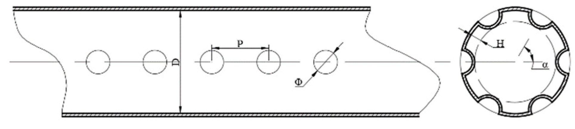
The seed tube is mainly composed of a horizontal conveying pipe, a vertical conveying pipe, and an elbow. According to the wall structure of the vertical conveying pipe, it is divided into corrugated type, hole-type, and ordinary round-tube seed tubes. Figure 2 and Figure 3 are divided into corrugated and hole-type seed tubes, where D is the diameter of the seed tube, H is the depth of the corrugations or holes, P is the spacing of the corrugations or holes, L is the length of the corrugations or holes, φ is the diameter of the holes, and α is the angle between the two holes. The specific parameters of the three pipelines are listed in Table 1.
2.1.3. Particle–Wall Collision Analysis
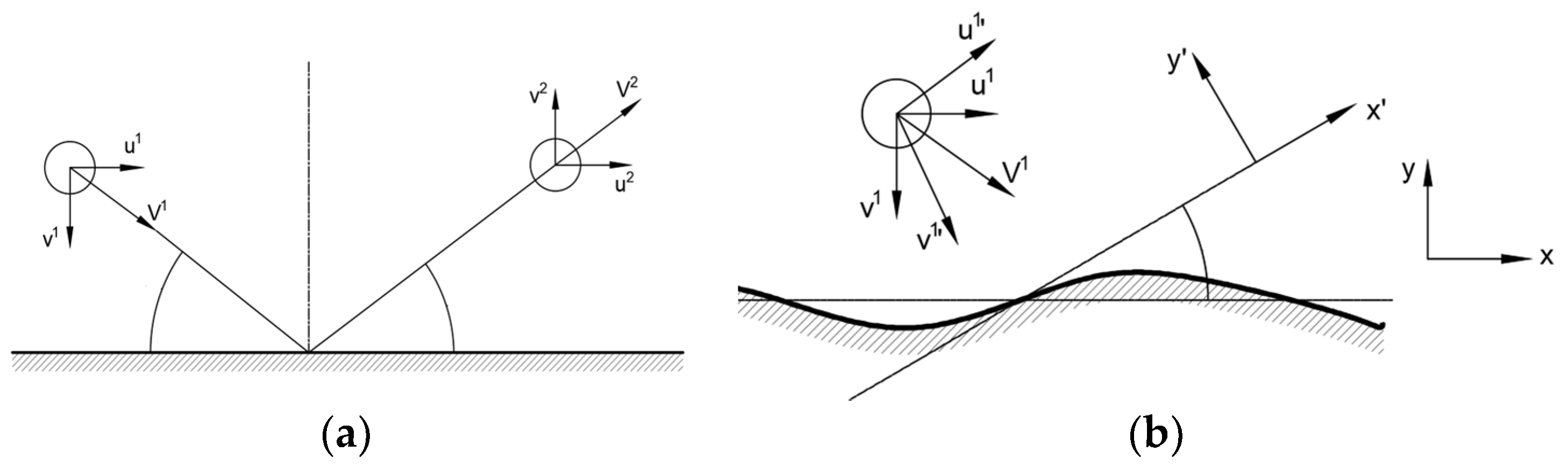
It is inevitable that the particles collide with the wall in the pipeline. The collision between the particles and the wall will affect the momentum of rapeseeds, change the direction of movement of the seeds, and have a direct impact on the stable transportation of seeds [24]. The rapeseeds were replaced by spherical particles, and the contact and collision behavior of the rapeseeds was analyzed according to the characteristics of the tube wall. Figure 4a shows the collision process between rapeseeds and the wall of the smooth seed tube. The collision restitution coefficient and friction coefficient are used to describe the partial velocity of the seeds after the collision, and represent the tangential and normal velocity components of the rapeseed before the collision, respectively, and and respectively represent the tangential velocity of the rapeseed after the collision. The velocity component and the normal velocity component, according to the momentum theorem, the velocity component after the seed collision can be obtained:
The collision process between rapeseeds and the concave-convex surface is shown in Figure 4b. Due to the addition of corrugations and hole structures, the wall surface of the seed tube changes from a smooth surface to a concave-convex surface. The random wall roughness angle is used to indicate when the seeds randomly collide with the wall surface. The inclination angle of the contact surface, , significantly affects the rebound direction and speed of the seeds after the collision. At this time, a virtual wall is introduced, and the coordinates are converted to analyze the speed of the particles after the collision. The tangential velocity component and the normal velocity component after the collision of the eye wall surface, the collision process of rapeseeds based on the virtual wall surface satisfies the following relationship:
Formulas (3) and (4) suggest that the velocity component after the seed collides is correlated with the collision restitution coefficient, friction coefficient, and roughness angle. The actual collision process between the seed and the wall is difficult to accurately describe and analyze due to the randomness of the roughness angle . Therefore, the DEM-CFD gas-solid coupling method was used to predict the movement of particles in the seed tube.
2.2. Numerical Simulation
2.2.1. Model of Particle
The movement of particles in the airflow field follows Newton’s second law, and is affected by gravity, buoyancy, fluid resistance, Saffman lift, and Magnus lift, the contact force between particles and the wall, etc. [25]:
where represents particle mass, represents the fluid drag force, represents the resultant force of gravity and buoyancy, represents the Saffman lift force, represents the Magnus lift force, and represents particle-wall contact force.
The contact force between the particle and the wall is:
where represents equivalent eccentric mass, represents restitution coefficient, represents normal stiffness, tangential stiffness, represents normal component of relative velocity, and represents normal component of relative velocity.
The normal stiffness and tangential stiffness in the above formula are calculated as:
where , and represent Young’s modulus, equivalent shear modulus, and equivalent radius, and represents normal overlap quantity.
2.2.2. Model of Fluid
The standard k-ε model is selected as the turbulence model. When studying the turbulent motion of the draft tube, the disturbance phenomenon caused by the wall structure to the airflow and the airflow pressure drop in the draft tube need to be paid attention to, such that the Darcy friction coefficient is used to describe it. The transport formula corresponding to the standard k-ε model is as follows:
where represents turbulent kinetic energy, ε represents dissipation rate of turbulence energy, represents Turbulent kinetic energy produced by mean velocity gradient, and represent Prandt number corresponding to turbulent kinetic energy and turbulent dissipation rate, and are empirical constant, and represent motion distance in different directions, represents airflow velocity in different directions.
The Darcy friction coefficient [26] is expressed as follows:
where denotes the pressure drop between the two test sections, Pa; represents the relative diameter of the pipe diameter D, m; expresses the distance between the two test sections, m.
2.2.3. DEM-CFD Coupling
The DEM-CFD coupling simulation is to add fluid-particle interaction force on the particles according to Newton’s second law, and the drag force is the main fluid-particle interaction force. When only the force of the fluid on the particles is considered, the Freesteam drag model is usually used for calculation, and its calculation formula is written as follows:
where is the airflow velocity, m/s; is the particle velocity, m/s; A is the particle cross-sectional area, m2; is the single particle drag coefficient; is the Reynolds number; is the sphericity; is the cross-section sphericity.
DEM-CFD coupling can be divided into one-way coupling method and two-way coupling method in accordance with the fluid-particle interaction mode. The difference lies in whether the effect of particles on the fluid is considered. When the particles occupy less than 10% of the airflow volume in the seed tube, the particles slightly affect the flow field distribution, and the force of the particles on the fluid can be ignored, such that the one-way coupling method is adopted. The one-way coupling method can save computing resources and shorten the computing time. Since the effect of particles on the fluid is ignored, the fluid motion can be calculated with the continuity formula and the momentum conservation formula with locally averaged variables. The continuity formula for fluid motion is as follows:
The momentum conservation formula is as follows:
where denotes fluid density; is the fluid velocity; is the pressure of fluid; is the coordinates; is the effective viscosity.
2.2.4. Numerical Setup
In the EDEM-CFD coupled simulation, the commercial CFD software ANSYS Fluent 2020 was used to solve the fluid phase; with air as the medium carrier, the density of which was 1.225 kg/m3, the viscosity was 1.789 × 10⁻⁵ Pa s, and the airflow velocity was 16 m/s. The particle phase was solved using EDEM 2021. In the case of DEM-CFD coupling, the time step of EDEM should be much lower than that of Fluent, therefore, the time steps of EDEM and Fluent are set to 5 × 10⁻⁶ and 1 × 10⁻³ s, respectively. Set the number of Fluent steps to 2000, that is, the total simulation time is 2 s. In the simulation, the seed tube material is aluminum alloy. The material characteristics of seeds and aluminum alloy and their mechanical properties [7,8] and air flow field parameters are shown in Table 2.
The thousand-grain weight of the rapeseeds in the simulation test was 3.8 g. According to the seeding amount of rapeseed per mu and the forward speed of the machine, the inlet of the seed tube was set to generate 560 rapeseeds per second. The time for generating rapeseed particles at the entrance of the seed tube is 2 s, and the total simulation time was 2 s. Three types of air distribution in the seed tube and the movement characteristics of rapeseed particles were carried out. The velocity and force changes of a single rapeseed, the maximum speed and maximum force of the seed at each moment, and the distribution of rapeseeds in the seed tube were derived from EDEM to analyze the movement characteristics of rapeseed particles.
2.2.5. Mesh Dependence Analysis
Before modeling calculation, the mesh independence verification was performed first, and the optimal number of mesh is determined by considering the calculation workload and calculation accuracy. The seed tube model was divided into 161,088, 237,789, and 376,027 grids to verify the grid independence. The axial position Z = 70 mm was selected for comparison of axial velocity. It can be seen from Figure 5 that the number of mesh had a certain impact on the simulation results. When the number of mesh was 237,789 or 376,027, the calculation results tended to be consistent. Considering the accuracy of simu−lation results and the cost of simulation calculation, the number of mesh of seed tube flow field in this paper was 237,789.
3. Results
3.1. Model Validation
To verify the reliability of the simulation results, an ordinary round-tube seed tube was selected in this experiment, and the airflow velocity at the vertical conveying pipe under the condition of no material when the inlet velocity was 16 m/s was examined. In the test, the L-shaped pitot tube (the pitot tube coefficient: 0.99~1.01, the speed measurement range: 2~70 m/s) and the wind speed, pressure, and air volume meter were used to examine the wind speed. The pressure hole was perpendicular to the airflow direction. Four measurement points were evenly arranged along the outlet direction (including A, B, C, D), and the distance between the measurement points was 100 mm, and the distances from the outlet of the seed tube were 100 mm, 250 mm, 400 mm, and 550 mm, respectively. The distribution of the measurement points is shown in Figure 6. When the inlet wind speed was 16 m/s, the wind speed of different measuring points was examined 10 times, and the examined values are listed in Table 3.
As depicted in Table 2, the wind speed measurement test produced a certain measurement error, which may be due to the small-scale vibration of the Pitot tube under the action of the wind, resulting in the full pressure hole of the Pitot tube being not parallel to the airflow direction. After many repetitions of the test, its patency may deteriorate, thus causing biased measurement results.
After using the CFD-POST software to extract the data of each test point in the simulation results, the examined and simulated values of the wind speed at each measurement point at the exit were listed in Table 4. Errors in the table are shown as (|Analog value—Examined value|)/Examined value × 100%. It can be seen from the table that the airflow velocity examined by the simulated value and the examined value basically gradually decreased along the outlet direction, indicating that the approximate trend of the simulated result and the actual examined value was the same, and the simulated value at the measurement points B, C, D and the examined value were larger than that of A. The possible reason is that the last three measuring points were close to the curved part of the flow, and the airflow field is relatively disordered, such that there may be a certain deviation between the simulated value and the examined value. After calculation, the average error of the four positions was 6.71%, which is acceptable in agricultural engineering applications with such complex factors. Therefore, it can be confirmed that the air-feeding seed metering system is used in this paper and the simulation results of the internal flow field in the tube are reliable.
3.2. Effect of Seed Tube Structure on Airflow Field
Figure 7 presents the airflow velocity and pressure at the respective point extracted along the outline of the seed tube for different types of seed tubes to analyze the airflow velocity close to the wall of the seed tube. As depicted in the figure, the addition of the pressurized structure of the seed tube affected the air pressure and speed. In the elbow part of the seed tube, the airflow speed increased, while the pressure decreased rapidly. The supercharging structure significantly affected the airflow speed of the elbow part. When the corrugated supercharging was used, the airflow speed of the elbow part increased dramatically to 32.48 m/s. When the hole was pressurized, the maximum speed of the elbow part was 26.20 m/s. However, the airflow velocity of the ordinary round-tube seed tube without the pressurized structure slightly fluctuated, whereas the pressurized structure slightly affected the airflow velocity at the horizontal conveying pipe and the vertical conveying pipe. The pressurized structure significantly affected the internal pressure of the seed tube. The pressure value of the seed tube with corrugated pressurization is the highest, the hole-type is the second, and the pressure value of the ordinary roundtube seed tube is the lowest. Sharply reduced, after entering the elbow, the airflow pressure recovers, and the minimum pressure values of the three kinds of seed tubes are basically the same. Among the three kinds of seed tubes, the pressure loss of the corrugated tube was the smallest. It can be seen that the corrugated tube has better flow field characteristics, the pressure loss in the seed tube is small, and the airflow velocity is better.
Figure 8 shows the motion characteristics of seeds of three types of seed tubes when the airflow velocity is 16 m/s and the seed supply is 560 seeds/s. The seeds enter the pipe in an orderly manner. When passing through the elbow, the seed group moves along the pipe wall. Due to the collision and rebound between the seed group and the pipe wall, the stable seed flow begins to disperse. The density of the conveyed seed particle group is reduced, and the problem of intermittent conveying. The corrugated and hole-type seed tubes induce continuous fluctuations in the air flow due to their intermittent curved surfaces. The airflow fluctuations affect the running of the seeds, such that the dispersed seed flow is re-aggregated and continuously conveyed to the distributor. The seed tube is conducive to the continuous and stable delivery of the seed flow.
3.3. Effect of Seed Tube Structure on Seed Movement Characteristics
Figure 9a presents the test result of tracking the speed of a single seed particle generated in various seed tubes when 560 seed particles are generated per second. As depicted in the figure, the corrugated tube is the same as the ordinary round-tube seed tube when the seed is in the seed tube for 0~0.3 s. The force of the round tube is basically the same, while in the hole-type tube, there is a surge of force due to the collision between the seeds flowing through the elbow and the wall surface. Due to the different stagnation time of the seeds in the seed tube, there is one force change “wave peak” in the corrugated seed tube, and two force change “wave peaks” in the hole-type seed tube, indicating that the seeds are affected by the wall structure. This indicates that the speed of seeds varies alternately due to the influence of the wall structure, which makes the distribution of seeds more uniform in the pressurized tube. It can be seen from Figure 9b that the maximum resultant force on the seed particles in the corrugated, ordinary round-tube seed tube, and hole-type seed tubes is 0.35, 0.14, and 0.43 N, respectively, and the resultant force on the seed particles in the seed tube fluctuates significantly, indicating that the corrugation and the pocket structure increase the probability of the seeds colliding with the wall, resulting in the particle-wall collision force.
Figure 10a presents the speed test results of tracking the first seed particles generated in various seed tubes when 560 seed particles were generated per second. The maximum speed of seed particles in the tube reached 4.79, 4.35, and 5.18 m/s, respectively, and the stagnation time of seeds in the seed tube was 0.38, 0.48, and 0.30 s, respectively, thus suggesting that the ordinary round-tube seed tube exhibits high transportation efficiency but high speed. The force and speed of the seed particles increase when the seed particles collide with the main body of the distribution device, thus leading to an increase in the seed breaking rate. After the seeds in the ordinary round-tube seed tube pass through the elbow part, the seed speed increases linearly, while the corrugated and nested seeds increase linearly. The speed of the seeds in the eye-type seed tube shows a fluctuating trend, and the speed variation range of the corrugated tube is small, which is conducive to the stable transportation of the seeds. The speed of the seeds at the outlet are 5.18, 1.73, and 3.76 m/s. According to the elastic collision analysis between the fertilizer particles and the distribution device in the literature [27], it can be seen that the crushing rate of the material is correlated with the speed of the material particles and the distributor approaching each other. The breakage rate of the type and hole-type seed tubes is lower than that of the ordinary round-tube seed tube. As depicted in Figure 10b, the maximum velocity distribution in the corrugated and hole-type seed tubes shows a trend similar to “sinusoidal fluctuation”, indicating that the airflow velocity fluctuates up and down, which increases the collision between the seeds and the wall of the seed tube, which can promote a more even distribution of rapeseeds before entering the distributor.
4. Conclusions
In this paper, the DEM-CFD coupling method was used to simulate the effect of the structure of different vertical conveying pipes of the air-feeding seed metering system on the seed movement characteristics. It was verified by the bench test that the DEM-CFD coupling simulation can be well described. The movement of the seeds in the seed tube draw the following conclusions:
- The main structural parameters of the corrugated, ordinary round-tube, and hole-type seed tubes were determined. Based on the Herz contact model, the collision contact between rapeseeds and the wall surface was analyzed when the wall of the seed tube was smooth and uneven. During the process, the virtual wall was used to study the collision of seeds on the concave-convex tube wall, so as to obtain the motion formula after the rapeseeds collided with the tube wall.
- In this paper, the effect of the vertical conveying pipe structure of the seed guiding pipe on the uniformity of the seed flow was determined. The gas-solid coupling method of DEM-CFD was used to analyze the distribution of the air flow field of the seeds in the corrugated, hole-type, and ordinary round-tube seed tubes, and the movement characteristics of rapeseeds in different seed tubes were analyzed. The results show that the vertical conveying tube of the seed tube plus the corrugated or hole-type shape significantly affected the airflow field in the seed tube. The maximum airflow velocity was 32.48 and 26.20 m/s, respectively; the vertical conveying pipe of the seed tube plus corrugated and hole-shaped structures are beneficial in improving the damage to the uniform seed flow caused by the near-wall movement of the seed through the elbow part. The speed and force of the seeds in the corrugated and hole-shaped seed tubes were similar to the “sinusoidal fluctuation” trend, thus facilitating the uniform distribution of the seeds. However, the maximum force of the seeds in the hole-type seed tube fluctuated significantly, meaning they were more prone to the phenomenon of a surge in force. For the corrugated type, it will negatively affect the breakage of the seeds.
- The bench test verifies the feasibility of the DEM-CFD coupled simulation. The airflow velocity at the vertical conveying pipe was examined when the airflow velocity at the entrance of the ordinary round-tube seed tube was 16 m/s and there was no material. Compared with the airflow velocity obtained by simulation, it was found that the average error between the simulated value and the measured value was 6.71%, which is acceptable in the application of such engineering problems with complex factors in agricultural engineering. The reliability of the results of the simulation of the internal flow field in the seed tube of the air-feeding seed metering system.
Using the DEM-CFD coupling method, the movement mechanism of rapeseeds in the airflow field in the seed tube can be better described, and different pressurized structures can be compared. The DEM-CFD coupled simulation method has been extensively used in two-phase flow and gas flow transport to visualize particle motion and investigate the source of differences. Numerical simulation of the movement of seeds in different seed tubes based on the DEM-CFD coupling method can provide a reference for the optimization of the air-feeding seed metering.
Author Contributions
Conceptualization, Y.X. and M.W.; methodology, Y.X.; software, H.L.; validation, Z.M., H.L. and Y.X.; formal analysis, M.W.; investigation, Z.M.; resources, M.W.; data curation, Y.X.; writing—original draft preparation, Y.X.; writing—review and editing, Y.X.; visualization, Y.X.; supervision, M.W.; project administration, H.L.; funding acquisition, H.L. All authors have read and agreed to the published version of the manuscript.
Funding
This research was funded by Postgraduate Scientific Research Innovation Project of Hunan Province. grant number “CX20210660”.
Institutional Review Board Statement
Not applicable.
Informed Consent Statement
Not applicable.
Data Availability Statement
All data are presented in this article in the form of figures and tables.
Conflicts of Interest
The authors declare no conflict of interest.
References
- Yazgi, A.; Degirmencioglu, A. Measurement of seed spacing uniformity performance of a precision metering unit as function of the number of holes on vacuum plate. Measurement 2014, 56, 128–135. [Google Scholar] [CrossRef]
- Lei, X.; Liao, Y.; Wang, L. Simulation of gas-solid two-phase flow and parameter optimization of pressurized tube of air-assisted centralized metering device for rapeseed and wheat. Trans. Chin. Soc. Agric. Eng. 2017, 33, 67–75. [Google Scholar]
- Downs, H.; Taylor, R. Evaluation of Pneumatic Granular Herbicide Applicators for Seeding Small Grains in Oklahoma. Appl. Eng. Agric. 1986, 2, 58–63. [Google Scholar] [CrossRef]
- Guler, I. Effects of flute diameter, fluted roll length, and speed on alfalfa seed flow. Appl. Eng. Agric. 2005, 21, 5–7. [Google Scholar] [CrossRef]
- Shirsath, S.; Padding, T.; Clercx, H. Cross-validation of 3D particle tracking velocimetry for the study of granular flows down rotating chutes. Chem. Eng. Sci. 2015, 134, 312–323. [Google Scholar] [CrossRef]
- Senturov, S. Process Study and Parametres Reasoning of a Centralized Air Eeding. Ph.D. Thesis, Ural State University, Gorki, Russia, 1979. [Google Scholar]
- Liao, Q.; Lei, X.; Liao, Y. Research progress of precision seeding for rapeseed. Trans. Chin. Soc. Agric. Mach. 2017, 48, 1–16. [Google Scholar]
- Lei, X.; Liao, Y.; Li, Z. Design and experiment of seed feeding device in air-assisted centralized metering device for rapeseed and wheat. Trans. Chin. Soc. Agric. Eng. 2015, 31, 10–18. [Google Scholar]
- Chang, L.; Zhang, X. Design and test of one-step centralized type pneumatic seeding system. Trans. Chin. Soc. Agric. Eng. 2011, 11, 136–141. [Google Scholar]
- Chang, L. Research and Experimental Analysis of Centralized Pneumatic Seeding System. Master’s Thesis, Shandong Agricultural University, Shandong, China, 2007. [Google Scholar]
- Chang, L.; Zhang, X.; Chen, Y. Design of the quantitative force feed in the air-stream central-type drill system. J. Agric. Mech. Research. 2007, 6, 66–67, +89. [Google Scholar]
- Liu, L.; Liu, Z.; Yang, X. Design and test on pneumatic No-till wheat planter. Trans. Chin. Soc. Agric. Mach. 2011, 42, 54–57. [Google Scholar]
- Liu, L.; Yang, X.; Li, C. Design of 2BMG-24 No-till wheat planter. Trans. Chin. Soc. Agric. Mach. 2009, 40, 39–43, +48. [Google Scholar]
- Zhai, G.; Bao, D.; Wang, Z. Design for metering device key parts of pneumatic grass seeder. Trans. Chin. Soc. Agric. Mach. 2014, 45, 47–51. [Google Scholar]
- Li, Y.; Liu, Y.; Liu, L. Distribution mechanism of aitflow in seed tube of different lengths in pneumatic seeder. Trans. Chin. Soc. Agric. Mach. 2020, 51, 55–64. [Google Scholar]
- Li, Y.; Liu, R.; Liu, C. Simulation and test of seed velocity coupling in seed tube of pneumatic seed metering device. Trans. Chin. Soc. Agric. Mach. 2021, 52, 54–61, +133. [Google Scholar]
- Li, Y.; Zhao, J.; Zhao, J. Biomimetic design and experiment of the distributor of pneumatic seeding system based on the crucian curve. Trans. Chin. Soc. Agric. Mach. 2022, 52, 80–87. [Google Scholar]
- Yatskul, A.; Lemiere, J.; Cointault, F. Influence of the divider head functioning conditions and geometry on the seed’s distribution accuracy of the air seeder. Biosyst. Eng. 2017, 161, 120–134. [Google Scholar] [CrossRef]
- Yatskul, A.; Lemiere, J.; Cointault, F. Establishing the conveying parameters required for the air seeder. Biosyst. Eng. 2018, 166, 1–12. [Google Scholar] [CrossRef]
- Dai, Y.; Luo, X.; Wang, Z. Design and xeperiment of rice pneumatic centralized seed distributor. Trans. Chin. Soc. Agric. Eng. 2016, 32, 36–42. [Google Scholar]
- Dai, Y.; Luo, X.; Zhang, M. Design and experiments of the key components for centralized pneumatic rice dry direct seeding machine. Trans. Chin. Soc. Agric. Eng. 2020, 36, 1–8. [Google Scholar]
- Dai, Y. Design and Experiment of Centralized Pneumatic Racedrilling Machine for Dry Land. Ph.D. Thesis, South China Agricultural University, Guangdong, China, 2018. [Google Scholar]
- Yang, L. Pneumatic Conveying Engineering; China Machine Press: Beijing, China, 2006. [Google Scholar]
- Chen, Q.; Liu, L. Numerical simulation of sphere motion in infinite-length pipe flow. In Proceedings of the 16th National Congress on Hydrodynamics, Jiangsu, China, 30 October 2021. [Google Scholar]
- Akhshik, S.; Behzad, M.; Rajabi, M. CFD-DEM approach to investigate the effect of drill pipe rotation on cuttings transport behavior. J. Pet. Sci. Eng. 2015, 127, 229–244. [Google Scholar] [CrossRef]
- Li, M.; Tariq, S.; Ebrahim, A. Geometric optimization for thermal–hydraulic performance of dimpled enhanced tubes for single phase flow. Appl. Therm. Eng. 2016, 103, 639–650. [Google Scholar] [CrossRef]
- Wang, L.; Liao, Q.; Liao, Y. Effects of distributor types on fertilizing performance in an air-assisted applicator. Trans. Chin. Soc. Agric. Eng. 2021, 37, 24–34+315. [Google Scholar]
Figure 1.
The schematic diagram of the pneumatic seeding system. 1. seed box; 2. centralized seed supply device; 3. seed-air flow mixing chamber; 4. fan; 5. distribution device; 6. seed tube; 7. seed metering pipe.
Figure 1.
The schematic diagram of the pneumatic seeding system. 1. seed box; 2. centralized seed supply device; 3. seed-air flow mixing chamber; 4. fan; 5. distribution device; 6. seed tube; 7. seed metering pipe.

Figure 2.
Diagram of corrugated pipe.

Figure 3.
Diagram of hole-type pipe.

Figure 4.
Collision process between rapeseeds and wall surface. (a) Collision with smooth wall; (b) collision with convex wall.
Figure 4.
Collision process between rapeseeds and wall surface. (a) Collision with smooth wall; (b) collision with convex wall.

Figure 5.
Mesh dependence analysis.

Figure 6.
Measuring point position map. (a) Location distribution of measuring points; (b) test device diagram.
Figure 6.
Measuring point position map. (a) Location distribution of measuring points; (b) test device diagram.

Figure 7.
Effect of pressurization type on airflow velocity and pressure in seed tube. (a) Variation curves of airflow velocity in different seed tube; (b) Variation curves of pressure in different seed tube.3.3. Effect of Seed Tube Structure on Seed Distribution.
Figure 7.
Effect of pressurization type on airflow velocity and pressure in seed tube. (a) Variation curves of airflow velocity in different seed tube; (b) Variation curves of pressure in different seed tube.3.3. Effect of Seed Tube Structure on Seed Distribution.

Figure 8.
Distribution of rapeseeds in different seed tubes.

Figure 9.
Force variation of single particle and maximum force diagram of particle in seed tube. (a) Effect of seed tube on stress of single seed; (b) Influence of seed tube on maximum force of seed.
Figure 9.
Force variation of single particle and maximum force diagram of particle in seed tube. (a) Effect of seed tube on stress of single seed; (b) Influence of seed tube on maximum force of seed.

Figure 10.
Plot of single particle velocity variation and maximum particle velocity in seed tube. (a) Effect of seed tube on stress of single seed; (b) Influence of seed tube on maximum force of seed.
Figure 10.
Plot of single particle velocity variation and maximum particle velocity in seed tube. (a) Effect of seed tube on stress of single seed; (b) Influence of seed tube on maximum force of seed.


Table 1.
Dimensional configurations of the tubes.
| Parameters | Corrugated Type | Holes-Type | Ordinary Tube Seed Tube |
|---|---|---|---|
| Inside diameter of tube, D (mm) | 40 | 40 | 40 |
| The depth of the corrugations or holes, H (mm) | 5 | 7 | |
| The spacing of the corrugations or holes, P (mm) | 20 | 20 | |
| The length of the corrugations or holes, L (mm) | 167 | 165 | |
| The diameter of the holes, φ (mm) | 6 | ||
| The angle between the two holes, α (mm) | 72 |
Table 2.
Simulation parameters.
| Case | Parameters | Values |
|---|---|---|
| EDEM software | time step/s | 5 × 10⁻⁶ |
| save interval/s | 0.01 | |
| acceleration of gravity/(m/s2) | 9.81 | |
| Fluent software | time step/s | 2 × 10⁻³ |
| save interval/s | 0.05 | |
| current density/(kg/m3) | 1.225 | |
| air viscosity coefficient/(Pa·s) | 1.789 × 10⁻⁵ | |
| Rapeseed | poisson ratio | 0.25 |
| shear modulus /Pa | 1.1 × 10⁷ | |
| density/(kg/m3) | 1060 | |
| Seed tube | poisson ratio | 0.3 |
| shear modulus /Pa | 2.7 | |
| density/(kg/m3) | 2700 × 1010 | |
| Rapeseed–rapeseed contact parameters | coefficient of restitution | 0.6 |
| coefficient of static friction | 0.5 | |
| dynamic friction factor | 0.01 | |
| Rapeseed–seed tube contact parameters | coefficient of restitution | 0.6 |
| coefficient of static friction | 0.3 | |
| dynamic friction factor | 0.01 |
Table 3.
Export speed 10 measurements and their average.
| Velocity/(m.s−1) | Position/(mm) | |||
|---|---|---|---|---|
| A | B | C | D | |
| 1 | 14.11 | 13.09 | 15.40 | 15.43 |
| 2 | 13.70 | 13.97 | 14.05 | 15.60 |
| 3 | 14.74 | 14.65 | 15.54 | 15.86 |
| 4 | 14.62 | 13.03 | 14.23 | 16.10 |
| 5 | 12.90 | 14.11 | 15.91 | 15.80 |
| 6 | 14.09 | 14.56 | 15.82 | 15.59 |
| 7 | 13.95 | 14.64 | 15.68 | 15.66 |
| 8 | 14.25 | 13.86 | 16.05 | 15.49 |
| 9 | 14.30 | 14.29 | 15.22 | 16.08 |
| 10 | 13.56 | 15.33 | 15.93 | 15.76 |
| average | 14.02 | 14.15 | 15.38 | 15.74 |
| standard deviation | 0.51 | 0.68 | 0.67 | 0.22 |
Table 4.
Comparison of simulated value and examined value of outlet velocity.
| Position/(mm) | Gas Velocity/( m.s−1) | Errors | |
|---|---|---|---|
| Simulation Value | Examined Value | ||
| A | 14.35 | 14.02 | 2.35 |
| B | 15.48 | 14.15 | 9.40 |
| C | 16.52 | 15.38 | 7.41 |
| D | 16.95 | 15.74 | 7.69 |
Publisher’s Note: MDPI stays neutral with regard to jurisdictional claims in published maps and institutional affiliations. |
© 2022 by the authors. Licensee MDPI, Basel, Switzerland. This article is an open access article distributed under the terms and conditions of the Creative Commons Attribution (CC BY) license (https://creativecommons.org/licenses/by/4.0/).
Share and Cite
MDPI and ACS Style
Xiao, Y.; Ma, Z.; Wu, M.; Luo, H. Numerical Study of Pneumatic Conveying of Rapeseed through a Pipe Bend by DEM-CFD. Agriculture 2022, 12, 1845. https://0-doi-org.brum.beds.ac.uk/10.3390/agriculture12111845
AMA Style
Xiao Y, Ma Z, Wu M, Luo H. Numerical Study of Pneumatic Conveying of Rapeseed through a Pipe Bend by DEM-CFD. Agriculture. 2022; 12(11):1845. https://0-doi-org.brum.beds.ac.uk/10.3390/agriculture12111845
Chicago/Turabian StyleXiao, Yao, Zitao Ma, Mingliang Wu, and Haifeng Luo. 2022. "Numerical Study of Pneumatic Conveying of Rapeseed through a Pipe Bend by DEM-CFD" Agriculture 12, no. 11: 1845. https://0-doi-org.brum.beds.ac.uk/10.3390/agriculture12111845
Note that from the first issue of 2016, this journal uses article numbers instead of page numbers. See further details here.