
Design and Experimental Study of Single Plant Harvester for Potato Breeding Experiments
 , ,
, ,
Abstract
:1. Introduction
2. Materials and Methods
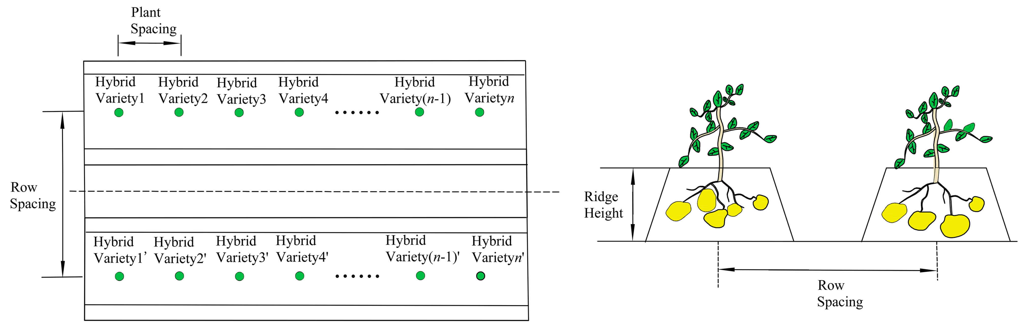
2.1. Agronomy in Breeding Trial
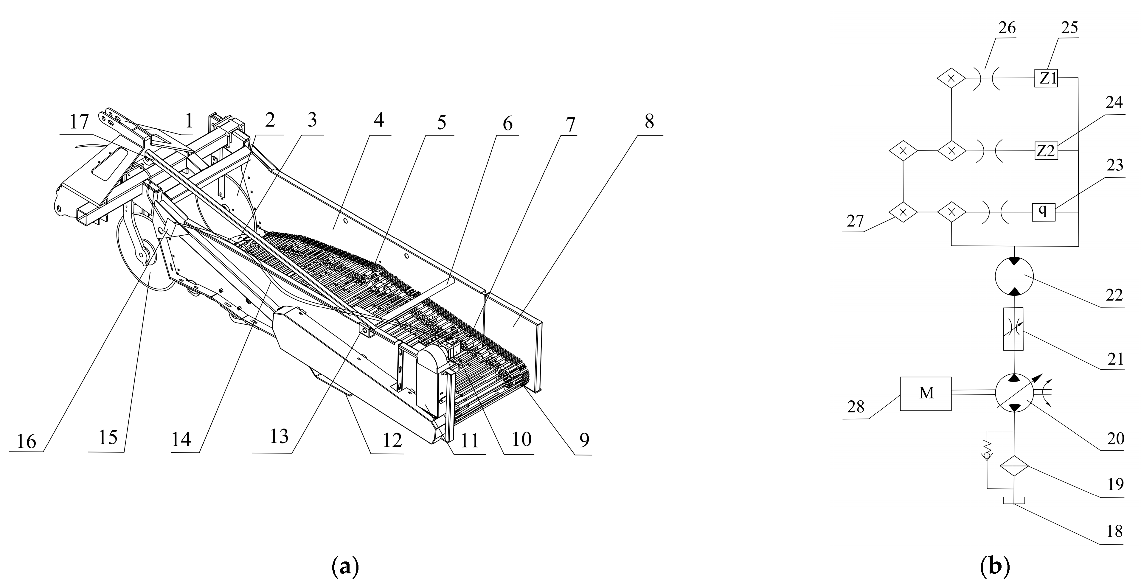
2.2. Overall Structural Design and Operating Principle
2.3. Excavation Device Design
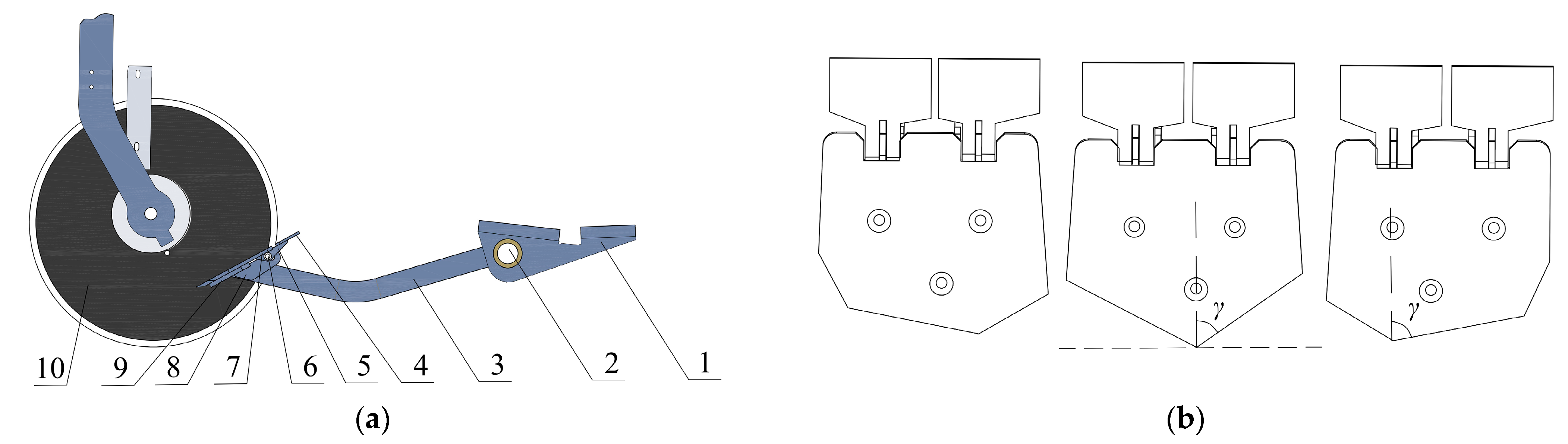
2.3.1. Excavation Device Structure
2.3.2. Excavation Device Geometric Parameters Selection
- The shovel blade bevel angle γ
- 2.
- The shovel face inclination angle α
- 3.
- The shovel body length L1
2.4. Conveying and Separating Device Design
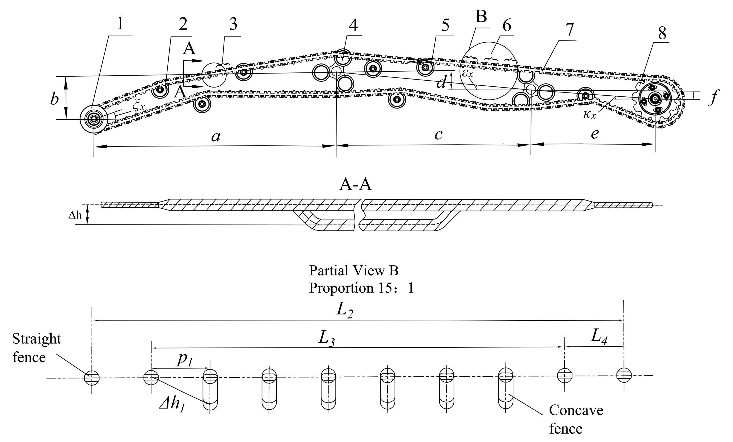
2.4.1. Conveying and Separating Device Structure
2.4.2. Fence Parameters Selection
2.4.3. Vibration Frequency Selection
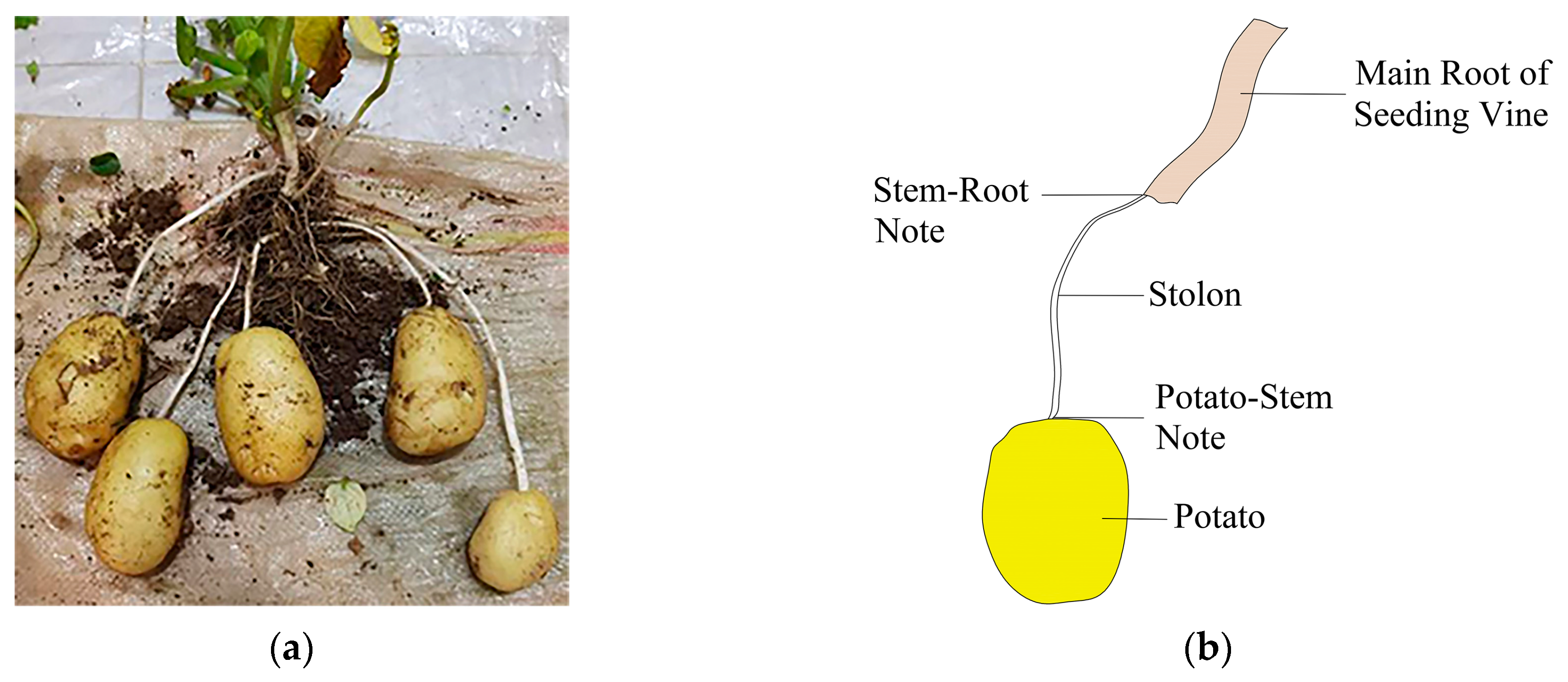
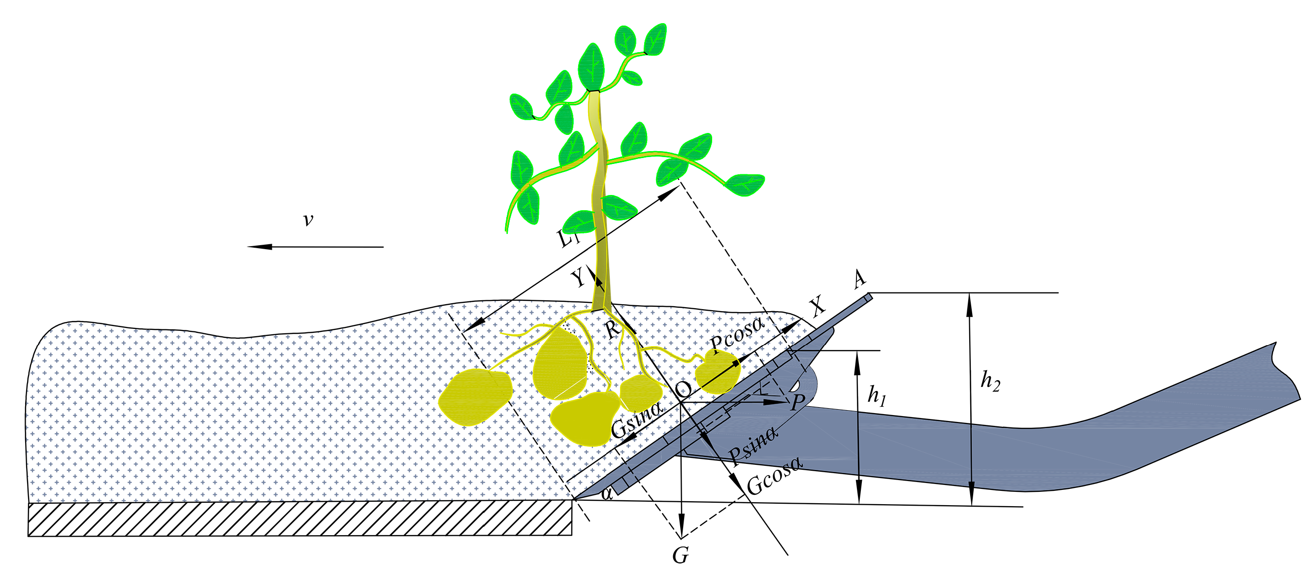
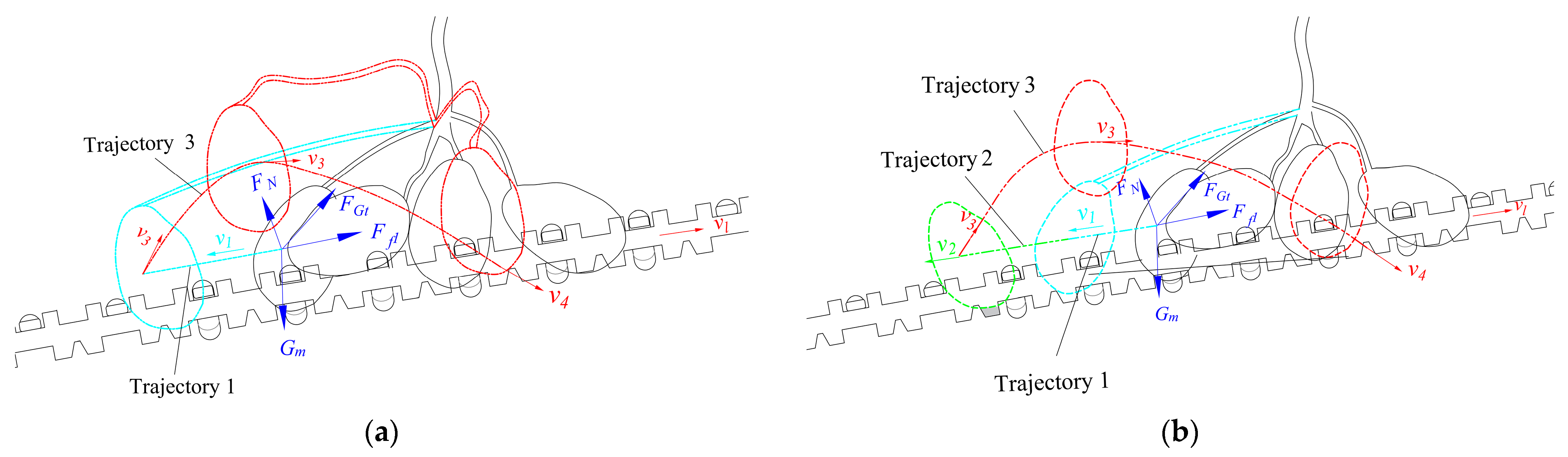
2.5. Potato Single Plant Movement Analysis
2.5.1. Potato Single Plant Digging Transition State Movement Analysis
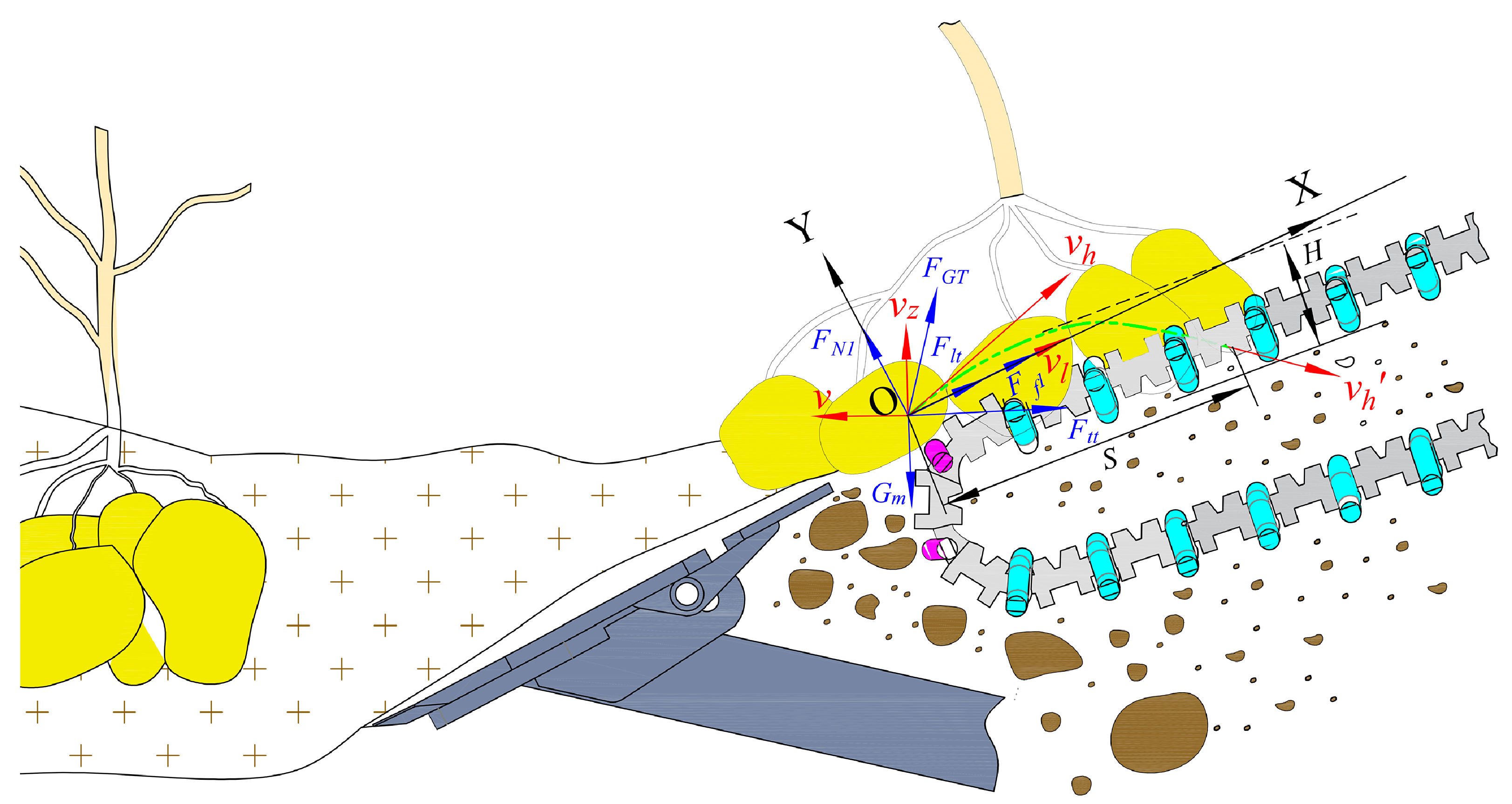
2.5.2. Potato Single Plant Transport State Movement Analysis
2.6. Key Performance Parameters of Potato Breeding Harvester
2.6.1. Single Plant Integrity Rate
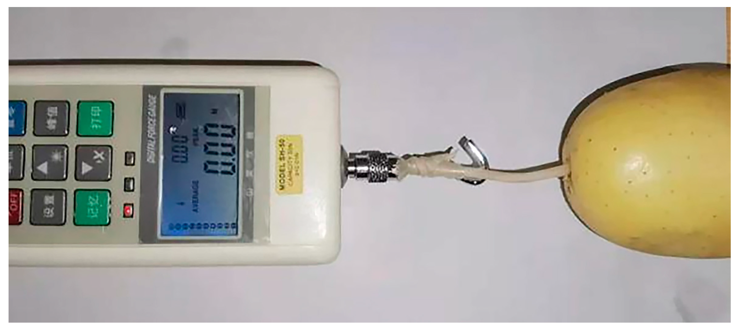
2.6.2. Potato Injury Rate
2.7. Key Experimental Factors of Potato Breeding Harvester
2.7.1. Conveying Speed to Forward Speed Ratio
2.7.2. Forward Speed
2.7.3. Rotational Speed of Rear-Vibration Device
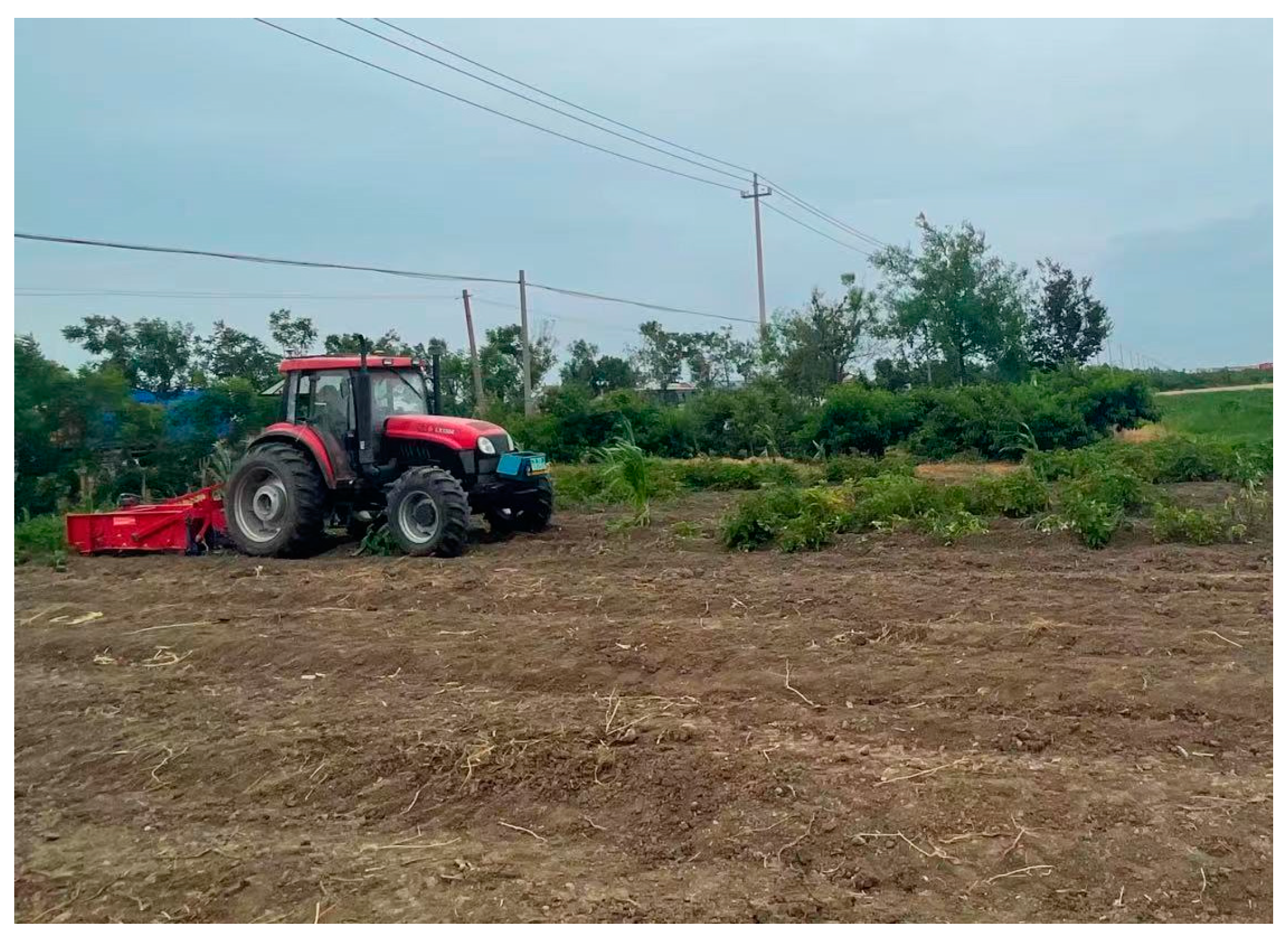
2.8. Experimental Environment and Materials
2.9. Field Experimental Programme
3. Results and Discussion
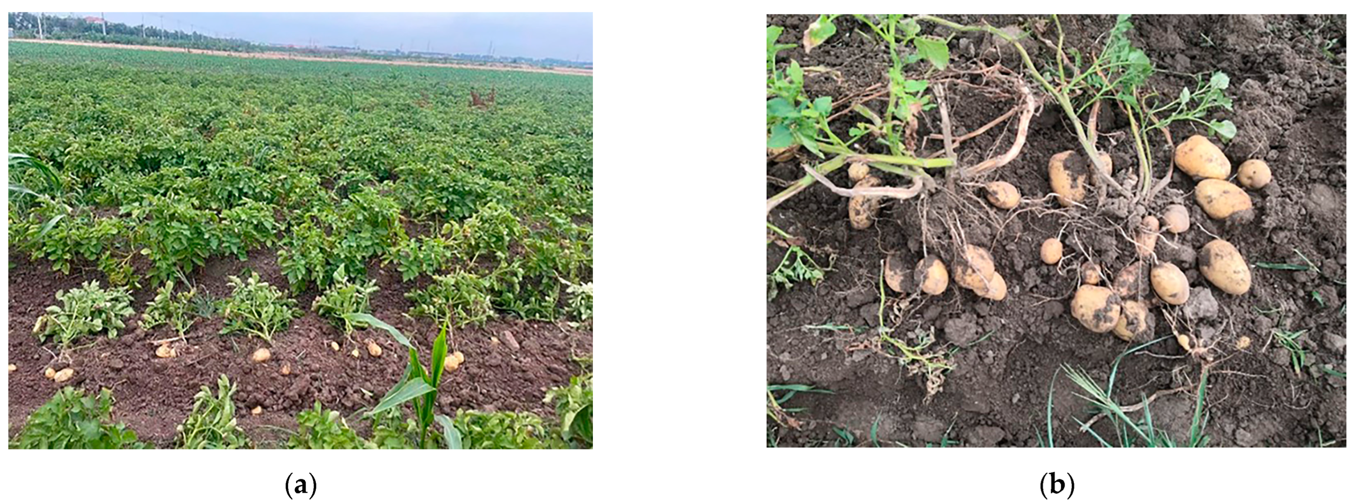
3.1. Field Experiment Results
3.2. Regression Analysis of Field Experiment
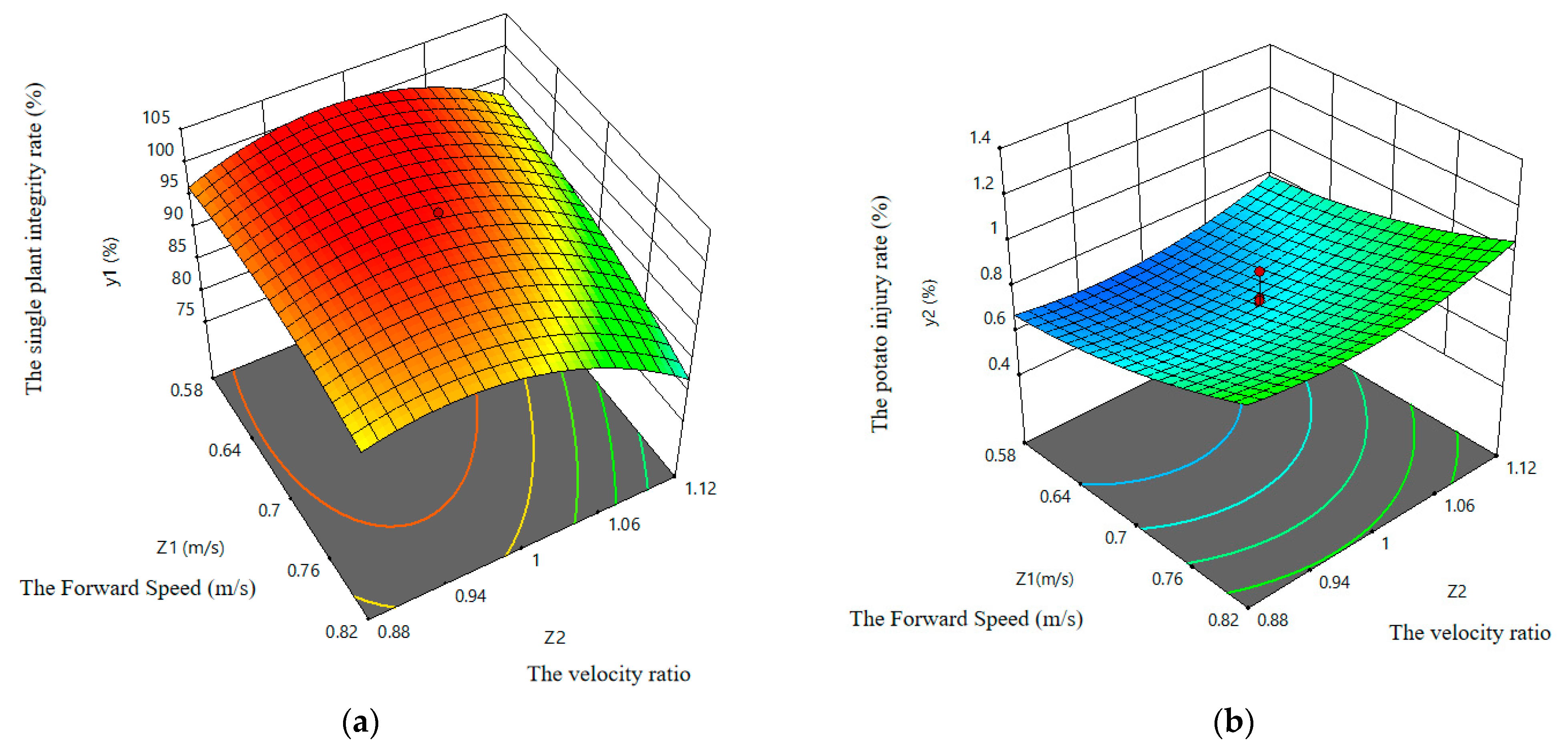
3.2.1. Single Plant Integrity Rate
3.2.2. Injured Potatoes Rate
3.3. Interaction Analysis of Field Experiment
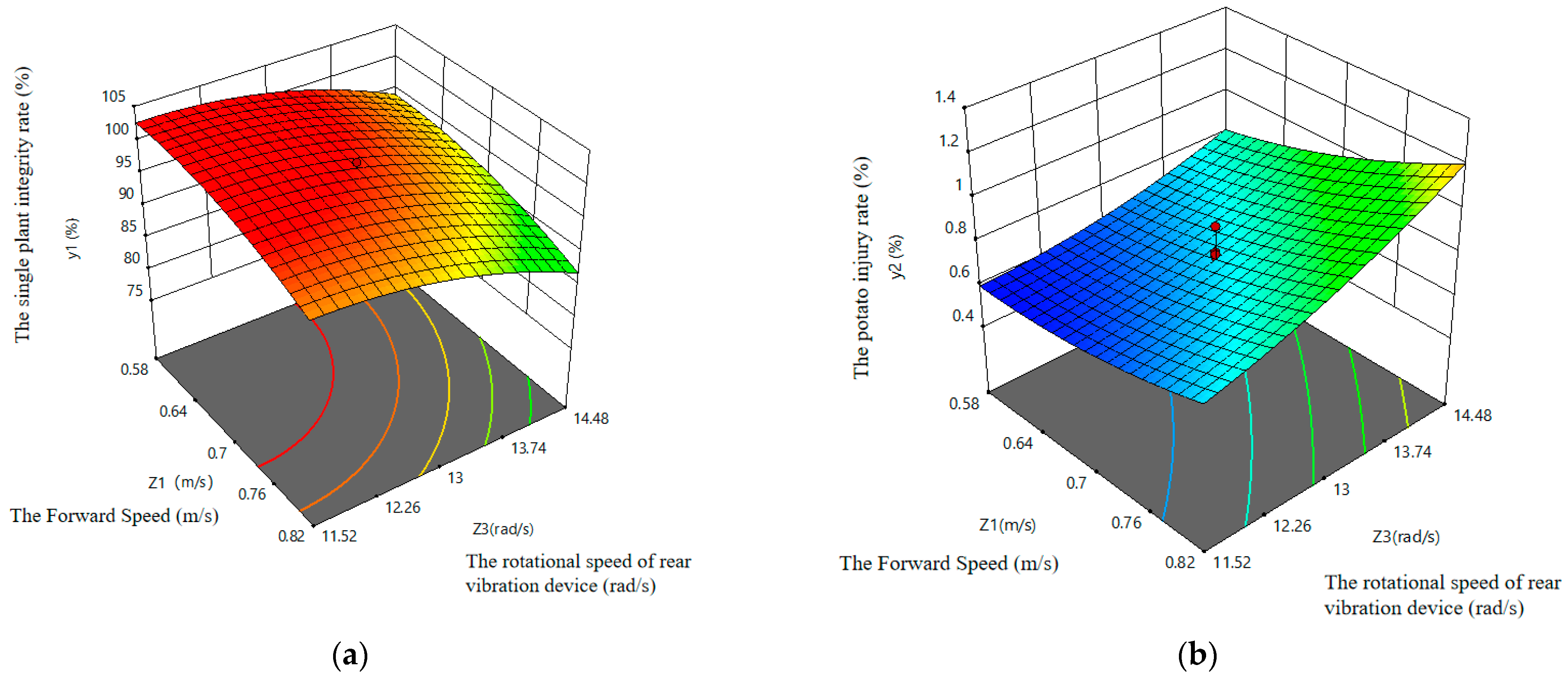
3.3.1. Interaction Analysis between Forward Speed and Conveying Speed to Forward Speed Ratio
3.3.2. Interaction Analysis between Forward Speed and Rotational Speed of Rear-Vibration Device
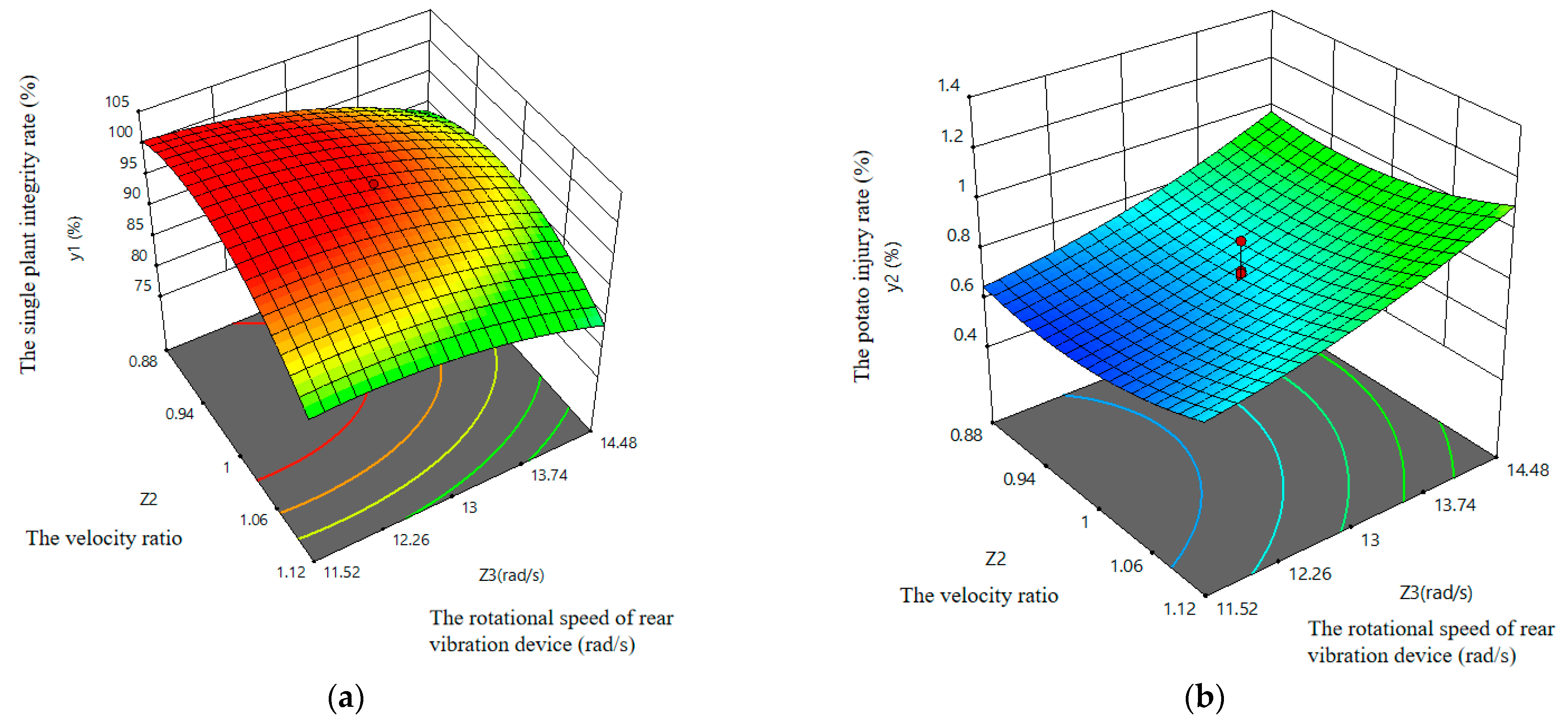
3.3.3. Interaction Analysis between Conveying Speed and Conveying Speed to Forward Speed Ratio
3.4. Performance Optimization of Field Experiment
4. Conclusions
Author Contributions
Funding
Institutional Review Board Statement
Informed Consent Statement
Data Availability Statement
Acknowledgments
Conflicts of Interest
References
- Mushinsky, A.A.; Vorontsova, E.S.; Aminova, E.V.; Saudabaeva, A.Z. Assessment of breeding hybrid potatoes in irrigated conditions of the steppe zone of the Southern Urals. IOP Conf. Ser. Earth Environ. Sci. 2021, 659, 012099. [Google Scholar] [CrossRef]
- Jiang, W.; Diao, P.S.; Zhang, H. Current situation of potato production and mechanized harvest in China. Agric. Equip. Veh. Eng. 2021, 59, 18–22. [Google Scholar]
- Stemerding, D.; Beumer, K.; Edelenbosch, R.; Swart, J.A.; de Vries, M.E.; Ter Steeg, E.; Almekinders, C.J.; Lindhout, P.; van Dijk, L.C.; Struik, P.C. Responsible innovation in plant breeding: The case of hybrid potato breeding. Plants 2023, 12, 1751. [Google Scholar] [CrossRef] [PubMed]
- Wang, D.; Zhang, C.Z.; Lin, T.R.; Yin, Y.H.; Han, F.; Han, S.E.; Han, W.J.; Tan, G.L. Exploration of Potato Breeding Program. Agric. Dev. Equip. 2021, 147–148. [Google Scholar]
- Zhou, B.D.; Li, Y.X.; Zhang, C.; Cao, L.W.; Li, C.S.; Xie, S.Y.; Niu, Q. Potato planter and planting technology: A review of recent developments. Agriculture 2022, 12, 1600. [Google Scholar] [CrossRef]
- Bhawna, D.; Salej, S.; Rasna, D.; Vinay, B.; Vikas, M.; Ajay, T.K.; Vinod, K.; Pandey, N.K.; Abhishek, R.; Singh, A.K. Digitalization of potato breeding program: Improving data collection and management. Heliyon 2023, 9, e12974. [Google Scholar] [CrossRef]
- Buitenwerfeth, H. Assessment of the behavior of potatoes in a cup-belt planter. Biosyst. Eng. 2006, 95, 35–41. [Google Scholar] [CrossRef]
- Ding, S.Y.; Lin, S.Y.; Zhou, X.Q.; Fu, M.; Liu, C.B.; Qi, X.Y. Research status of potato harvester and current situation and countermeasures of potato harvesting mechanization in guizhou. China South. Agric. Mach. 2022, 53, 54–57. [Google Scholar]
- Gierz, Ł.; Marciniak, A.; Przybyl, K.; Koszela, K.; Duda, A.; Szychta, M. Analysis of the strength of an innovative design of an organic farming potato harvester. J. Phys. Conf. Ser. 2022, 2212, 012028. [Google Scholar] [CrossRef]
- Anna, G. The method for potato root system measurements. Acta Agrobot. 2013, 54, 161–170. [Google Scholar] [CrossRef]
- Yu, L. A Potato Tuber Harvesting Device with Harvesting Function. CN113906892A, 11 January 2022. [Google Scholar]
- Tian, Y. Study on Structural Characteristics of Potato Tuber-Root Model and Design of Reconstruction Algorithms; Shenyang Agricultural University: Shenyang, China, 2019. [Google Scholar] [CrossRef]
- Fan, Y. Research on Potato Digging Mechanism Based on Based on Discrete Element Method and Design of Bionic Shovel; Shenyang Agricultural University: Shenyang, China, 2020. [Google Scholar] [CrossRef]
- Alexey, D.; PAndrey; Vitaly, Z.; Sergei, P.; Alexander, A.; Alexey, S.; Nikolay, S.; Maria, G. The results of laboratory studies of the device for evaluation of suitability of potato tubers for mechanized harvesting. Appl. Sci. 2022, 12, 2171. [Google Scholar] [CrossRef]
- Farmon, M.; Bakhadir, M.; Akmal, K.; Tura, R.; Shavkat, A.; Golib, S. Potato digger with a digging workpart of the “Paraplaw” type. E3S Web Conf. 2023, 365, 04021. [Google Scholar] [CrossRef]
- Yang, R.B.; Yang, H.G.; Shang, S.Q.; Xu, P.X.; Cui, G.P.; Liu, L.H. Design and test of poking roller shoving type potato harvester. Trans. Chin. Soc. Agric. Mach. 2016, 47, 119–126. [Google Scholar]
- Lyu, J.Q.; Yang, X.H.; Lyu, Y.N.; Li, Z.C.; Du, C.L. Analysis and experiment of potato damage in process of lifting and separating potato excavator. Trans. Chin. Soc. Agric. Mach. 2020, 51, 103–113. [Google Scholar]
- Schneider, C. Project Aims to Develop New Potato Varities; Southwest Farm Press: Atlanta, GA, USA, 2020; Volume 37, pp. 175–184. [Google Scholar]
- Wang, H.Y. Mountain Self Propelled Potato Combine Harvester Design and Experiment; Kunming University of Technology: Kunming, China, 2021. [Google Scholar] [CrossRef]
- Lyu, B.; Lyu, Z.Q. Design on vibrating type peanut harvester. J. Agric. Mech. Res. 2012, 34, 111–114. [Google Scholar] [CrossRef]
- Zhang, C.C.; Ma, Z.; Wang, J.F.; Qiu, X.W.; Liu, J.C. Research on wear characteristics of plough shovel based on discrete element method. Mod. Agric. Equip. 2021, 42, 25–29. [Google Scholar]
- Iwata, H.; Yu, S.; Mizushima, S.; Yamamura, S. Design of a discrete element method parameter identification system for the efficient excavation of mining shovels based on excavation resistance analysis. Int. J. Mech. Eng. Robot. Res. 2022, 11, 304–310. [Google Scholar] [CrossRef]
- Wu, B.; Huang, T.C.; Qiu, X.X.; Zuo, T.L.; Wang, X.S.; Xie, F.P. Design and experimental study of potato-soil separation device for sticky soils condition. Appl. Sci. 2021, 11, 10959. [Google Scholar] [CrossRef]
- Wei, Z.C.; Li, H.W.; Su, G.L.; Sun, C.Z.; Liu, W.Z.; Li, X.Q. Design and experiment of potato harvester using double cushions for low laying separation technology. Trans. Chin. Soc. Agric. Mach. 2019, 50, 140–152. [Google Scholar]
- NY/T648-2015; Technical Specification for Quality Evaluation of Potato Harvesters. China Standards Press: Beijing, China, 2015.
- Xin, L.L.; Liang, J.H. Design of conveyor separation device for potato harvester and analysis of its vibration characteristics. J. Comput. Methods Sci. Eng. 2022, 22, 1385–1392. [Google Scholar] [CrossRef]
- Kang, W.S.; Wen, X.Z. Developing a small commercial vibrating potato digger (I)—Assessment of kinematic design parameters. Appl. Eng. Agric. 2005, 21, 807–811. [Google Scholar] [CrossRef]
- Wei, Z.C.; Wang, X.H.; Li, X.Q.; Wang, F.M.; Li, Z.H.; Jin, C.Q. Design and experiment of crawler self-propelled sorting type potato harvester. Trans. Chin. Soc. Agric. Mach. 2023, 54, 95–106. [Google Scholar]
- Amer, N.N.K.; Ahmad, D.; Akhir, M.D.; Ishak, A.; Sulaiman, S. Design and development of an integrated slasher (pulverizer) for sweet potato harvester: A Review. IOP Conf. Ser. Mater. Sci. Eng. 2012, 36, 012007. [Google Scholar] [CrossRef]
- Liu, G.Y. Experimental Study on Potato Motion Characteristics during Potato Soil Separation Process; Inner Mongolia Agricultural University: Hohhot, China, 2022. [Google Scholar] [CrossRef]
- Yong, Y.S.; Hua, L.Y.; Jing, X.J. Parametric modeling and moving simulation of vibrating screen and tubers on potato harvester. Appl. Mech. Mater. 2012, 1935, 627–632. [Google Scholar] [CrossRef]


| Program | Parameters of “Holland 15” | Parameters of “Kexin 1” |
|---|---|---|
| Average growth width D/(mm) | 221 to 307 | 220 to 300 |
| Average potato mass m/(g) | 231.49 | 288.13 |
| Average potato length L/(mm) | 96.47 | 110.0 |
| Average potato width W/(mm) | 67.51 | 90.21 |
| Average potato thickness T/(mm) | 42.16 | 65.62 |
| Average growth height h/(mm) | 150 to 270 | 150 to 270 |
| State | ξx | εx | κx |
|---|---|---|---|
| State1 | |||
| State2 | |||
| State3 |
| Program | Parameter |
|---|---|
| Overall dimension (length × width × height) (mm) | 3680 × 1550 × 1200 |
| Auxiliary power (kW) | 29.42 to 44.13 |
| Operating width (mm) | 800 |
| Operating speed (km/h) | 1.5 to 6.82 |
| Operating hour productivity (hm2) | 0.2 to 0.3 |
| Excavation depth (mm) | 0 to 260 |
| Harvesting plant spacing (mm) | 250 to 350 |
| Code (xj) | Forward Speed Z1 (m∙s−1) | The Ratio of Speed Z2 (m∙s−1) | The Rotational Speed of Rear-Vibration Device Z3 (rad∙s−1) |
|---|---|---|---|
| 1.682 | 0.9 | 1.2 | 15.5 |
| 1 | 0.82 | 1.12 | 14.48 |
| 0 | 0.7 | 1.0 | 13 |
| −1 | 0.58 | 0.88 | 11.52 |
| −1.682 | 0.5 | 0.8 | 10.5 |
| Serial Number | z1 | z2 | z3 | y1 | y2 |
|---|---|---|---|---|---|
| 1 | 0.82 | 1.12 | 14.48 | 78.55% | 1.32% |
| 2 | 0.82 | 1.12 | 11.52 | 82.14% | 0.83% |
| 3 | 0.82 | 0.88 | 14.48 | 85.3% | 1.21% |
| 4 | 0.82 | 0.88 | 11.52 | 100% | 0.82% |
| 5 | 0.58 | 1.12 | 14.48 | 86.2% | 0.92% |
| 6 | 0.58 | 1.12 | 11.52 | 94.32% | 0.74% |
| 7 | 0.58 | 0.88 | 14.48 | 90.48% | 0.87% |
| 8 | 0.58 | 0.88 | 11.52 | 98.6% | 0.63% |
| 9 | 0.5 | 1.0 | 13.0 | 100% | 0.64% |
| 10 | 0.9 | 1.0 | 13.0 | 86.7% | 1.13% |
| 11 | 0.7 | 0.8 | 13.0 | 87.4% | 0.83% |
| 12 | 0.7 | 1.2 | 13.0 | 75.93% | 1.1% |
| 13 | 0.7 | 1.0 | 10.5 | 100% | 0.58% |
| 14 | 0.7 | 1.0 | 15.5 | 84.37% | 1.18% |
| 15 | 0.7 | 1.0 | 13.0 | 100% | 0.69% |
| 16 | 0.7 | 1.0 | 13.0 | 100% | 0.71% |
| 17 | 0.7 | 1.0 | 13.0 | 100% | 0.77% |
| 18 | 0.7 | 1.0 | 13.0 | 100% | 0.69% |
| 19 | 0.7 | 1.0 | 13.0 | 100% | 0.71% |
| 20 | 0.7 | 1.0 | 13.0 | 95.4% | 0.78% |
| 21 | 0.7 | 1.0 | 13.0 | 97.64% | 0.76% |
| 22 | 0.7 | 1.0 | 13.0 | 100% | 0.74% |
| 23 | 0.7 | 1.0 | 13.0 | 100% | 0.9% |
| Source | Sum of Squares | Degree of Freedom | Mean Square | F | p |
|---|---|---|---|---|---|
| Mode | 1379.77 | 9 | 153.31 | 43.85 | <0.0001 |
| x1 | 154.79 | 1 | 154.79 | 44.27 | <0.0001 ** |
| x2 | 201.52 | 1 | 201.52 | 57.64 | <0.0001 ** |
| x3 | 270.83 | 1 | 270.83 | 77.46 | <0.0001 ** |
| x1x2 | 32.20 | 1 | 32.20 | 9.21 | 0.0096 ** |
| x1x3 | 0.5253 | 1 | 0.5253 | 0.1502 | 0.7046 |
| x2x3 | 15.43 | 1 | 15.43 | 4.41 | 0.0557 |
| x12 | 55.60 | 1 | 55.60 | 15.90 | 0.0015 ** |
| x22 | 572.39 | 1 | 572.39 | 163.71 | <0.0001 ** |
| x32 | 82.79 | 1 | 82.79 | 23.68 | 0.0003 ** |
| Residual | 45.45 | 13 | 3.50 | / | / |
| Lack of fit | 24.11 | 5 | 4.82 | 1.81 | 0.2178 |
| Pure error | 21.35 | 8 | 2.67 | / | / |
| Sum | 1425.22 | 22 | / | / | / |
| Source | Sum of Squares | Degree of Freedom | Mean Square | F | p |
|---|---|---|---|---|---|
| Mode | 0.8629 | 9 | 0.0959 | 26.90 | <0.0001 |
| x1 | 0.2490 | 1 | 0.2490 | 69.86 | <0.0001 ** |
| x2 | 0.0395 | 1 | 0.0395 | 11.07 | 0.0055 ** |
| x3 | 0.3904 | 1 | 0.3904 | 109.53 | <0.0001 ** |
| x1x2 | 0.0002 | 1 | 0.0002 | 0.0561 | 0.8164 |
| x1x3 | 0.0265 | 1 | 0.0265 | 7.42 | 0.0174 * |
| x2x3 | 0.0002 | 1 | 0.0002 | 0.0561 | 0.8164 |
| x12 | 0.0355 | 1 | 0.0355 | 9.96 | 0.0076 ** |
| x22 | 0.0907 | 1 | 0.0907 | 25.45 | 0.0002 ** |
| x32 | 0.0329 | 1 | 0.0329 | 9.23 | 0.0095 ** |
| Residual | 0.0463 | 13 | 0.0036 | / | / |
| Lack of fit | 0.0119 | 5 | 0.0024 | 0.5552 | 0.7321 |
| Pure error | 0.0344 | 8 | 0.0043 | / | / |
| Sum | 0.9092 | 22 | / | / | / |
| Inspection Items | y1 | y2 |
|---|---|---|
| R | 0.9839 | 0.9742 |
| R2 | 0.9681 | 0.9490 |
| Adj R2 | 0.9460 | 0.9138 |
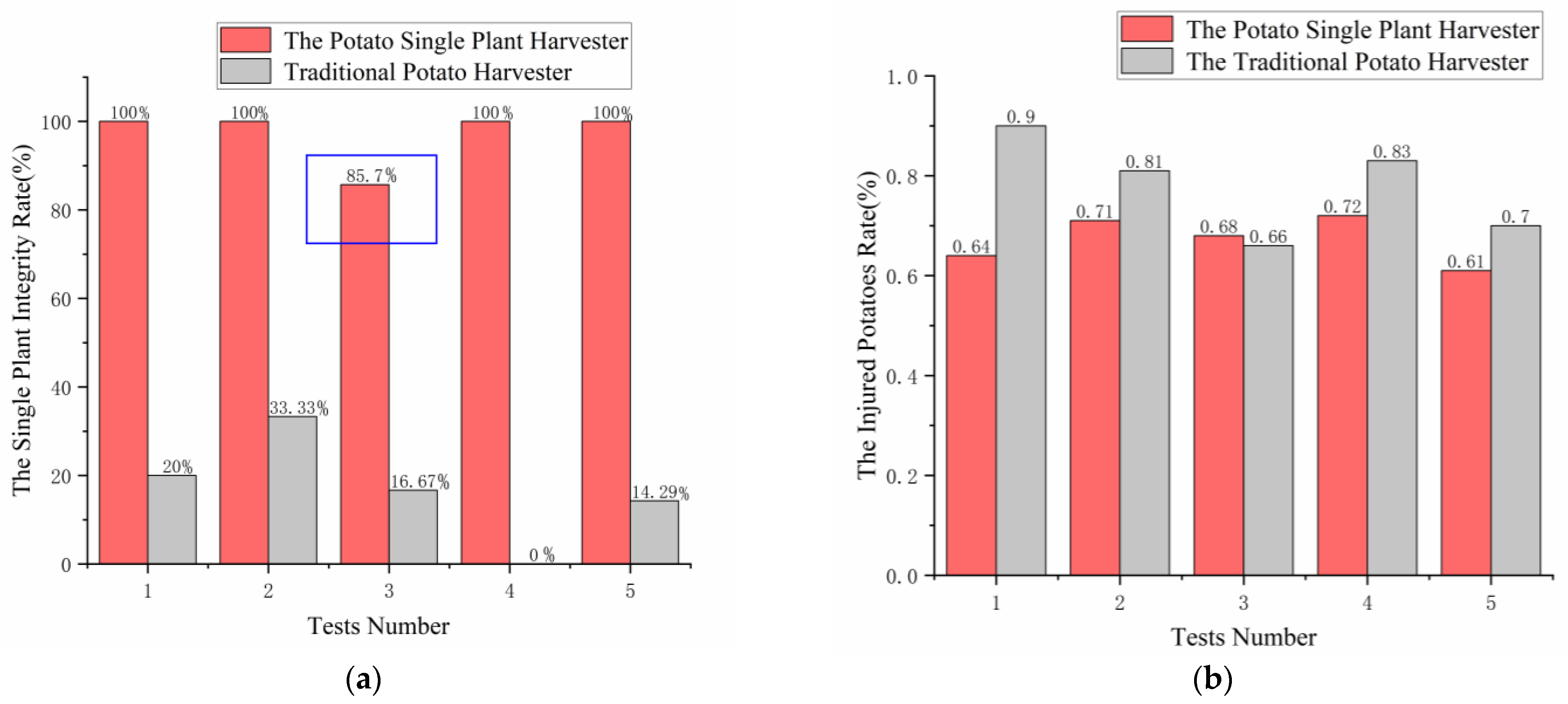
| Number of Experiments | Traditional Potato Harvester | Potato Breeding Harvester | ||
|---|---|---|---|---|
| y1 (mm) | y2 (mm) | y1′ (mm) | y2′ (mm) | |
| 1 | 20.00% | 0.90% | 100% | 0.64% |
| 2 | 33.33% | 0.81% | 100% | 0.71% |
| 3 | 16.67% | 0.66% | 85.7% | 0.68% |
| 4 | 0.00%% | 0.83% | 100% | 0.72% |
| 5 | 14.29% | 0.7% | 100% | 0.61% |
| Average value | 16.86% | 0.78% | 97.14% | 0.67% |
Disclaimer/Publisher’s Note: The statements, opinions and data contained in all publications are solely those of the individual author(s) and contributor(s) and not of MDPI and/or the editor(s). MDPI and/or the editor(s) disclaim responsibility for any injury to people or property resulting from any ideas, methods, instructions or products referred to in the content. |
© 2023 by the authors. Licensee MDPI, Basel, Switzerland. This article is an open access article distributed under the terms and conditions of the Creative Commons Attribution (CC BY) license (https://creativecommons.org/licenses/by/4.0/).
Share and Cite
Wang, W.; Yang, R.; Pan, Z.; Qing, Y.; Zhang, J.; Chen, D.; Guo, X.; Lyu, S. Design and Experimental Study of Single Plant Harvester for Potato Breeding Experiments. Agriculture 2024, 14, 71. https://0-doi-org.brum.beds.ac.uk/10.3390/agriculture14010071
Wang W, Yang R, Pan Z, Qing Y, Zhang J, Chen D, Guo X, Lyu S. Design and Experimental Study of Single Plant Harvester for Potato Breeding Experiments. Agriculture. 2024; 14(1):71. https://0-doi-org.brum.beds.ac.uk/10.3390/agriculture14010071
Chicago/Turabian StyleWang, Weijing, Ranbing Yang, Zhiguo Pan, Yiren Qing, Jian Zhang, Dongquan Chen, Xinyu Guo, and Shiting Lyu. 2024. "Design and Experimental Study of Single Plant Harvester for Potato Breeding Experiments" Agriculture 14, no. 1: 71. https://0-doi-org.brum.beds.ac.uk/10.3390/agriculture14010071