Article

Two-Dimensional Jamming Recognition Algorithm Based on the Sevcik Fractal Dimension and Energy Concentration Property for UAV Frequency Hopping Systems

1
College of Information and Communication Engineering, Harbin Engineering University, Harbin 150001, China
2
China Research Institute of Radiowave Propagation, Xinxiang 453000, China
*
Author to whom correspondence should be addressed.
Submission received: 27 September 2020 / Revised: 27 October 2020 / Accepted: 4 November 2020 / Published: 6 November 2020

Abstract

:
Unmanned aircraft vehicle frequency hopping (UAV-FH) systems face multiple types of jamming, and one anti-jamming method cannot cope with all types of jamming. Therefore, the jamming signals of the environment where the UAV-FH system is located must be identified and classified; moreover, anti-jamming measures must be selected in accordance with different jamming types. First, the algorithm extracts the Sevcik fractal dimension from the frequency domain (SFDF) and the degree of energy concentration from the fractional Fourier domain of various types of jamming. Then, these parameters are combined into a two-dimensional feature vector and used as a feature parameter for classification and recognition. Lastly, a binary tree-based support vector machine (BT-SVM) multi-classifier is used to classify the jamming signal. Simulation results show that the feature parameters extracted by the proposed method have good separation and strong stability. Compared with the existing box-dimensional recognition algorithm, the new algorithm not only can quickly and accurately identify the type of jamming signal but also has more advantages when the jamming-to-noise ratio (JNR) is low.

1. Introduction

Opportunities for combat are fleeting in modern warfare, and each combat unit of war is connected by the data link as a whole; thus, the real-time tactical intelligence can be shared among each combat unit. Therefore, the reliability of information transmission is important to obtain a victorious war in the unmanned aircraft vehicle (UAV) data link; thus, the anti-jamming performance of the UAV data link must be improved to ensure the reliability of data transmission [1]. The jamming faced by the UAV-frequency hopping (FH) system is mostly suppressed jamming, which includes broadband noise jamming (BNJ), narrowband noise jamming (NNJ), single-tone jamming (STJ), multi-tone jamming (MTJ), pulse jamming (PJ), and linear frequency modulation jamming (LFM) [2,3].
Each type of anti-jamming technology can only counter one type of jamming pattern, and no one anti-jamming technology can counter all types of jamming. At present, the development direction of anti-jamming technology for UAV systems is based on the intelligent anti-jamming technology of cognitive radio (CR) [4,5]. Cognitive frequency hopping (CFH) combines the dynamic spectrum access technology of CR with FH anti-jamming technology, and it generates anti-jamming strategies by sensing, learning and evaluating the communication environment [6,7].
A block diagram of the UAV-FH system is shown in Figure 1. First of all, the communication receiver monitors the surrounding spectrum environment through the jamming cognitive module while receiving information. It detects whether there is jamming in the selected frequency band, and detects the types of jamming in various spaces such as time domain, frequency domain, and time-frequency domain. Then, the results of the jamming cognitive module are transmitted to the cognitive decision module. The cognitive decision module analyzes the cognitive results through computing and intelligent learning and selects the best communication strategy [8]. The spectrum dynamic allocation module dynamically adjusts the frequency set and communication strategy of the FH system according to the result of the cognitive decision module. Finally, this parameter is sent to the receiver and transmitter through a reliable channel. In order to better improve the anti-jamming performance of the CFH system, this paper studies the jamming recognition algorithm.
Reference [9] identified jamming patterns on the basis of tree-like classifier. This methods are mainly based on binary classification, which is complicated for multiclass problem processing. In [10,11,12], the direct spread spectrum, transform domain, and FH systems were taken as carriers and used time domain and frequency domain characteristics to classify various types of jamming. Then, a decision tree was used for classification; the decision threshold in this method is the empirical value obtained by simulation. However, considering the overall recognition performance, the threshold value of the decision tree is slightly large, thus affecting the performance of other jamming. For this problem, Fang et al. adopted the rapid identification method of the classic ID3 decision tree algorithm in [13]. However, this algorithm has a low recognition rate when the jamming-to-noise ratio (JNR) is lower than −5 dB.
Liang extracted five feature parameters from the time domain, frequency domain, and transform domain, realized the recognition of six interference patterns, and compared the two classifiers of decision tree and support vector machine (SVM) [14]. Although the algorithm reduces the complexity of extracting feature parameters, it still uses the method of manually setting the decision tree threshold, and the established SVM multi-classifier has a slow operation speed when the number of samples is large. Reference [15] proposed an SVM jamming classification algorithm based on signal feature space. The literature shows that this algorithm requires a large amount of calculation and requires a high JNR to improve the recognition effect.
Wang et al. extracted the extreme value orders and the peak orders of the received signal in the Fractional Fourier Transform (FrFT) domain and used them as the classification recognition feature. Lastly, the fuzzy decision method was used to obtain classification and recognition results on the basis of different feature parameters [16]. Although the algorithm improves the credibility of classification and recognition, the complexity of the algorithm is relatively high. Huang et al. proposed a new idea in [17], extracting the fractal box dimension and two wavelet packet energy characteristic parameters as the jamming signal characteristic parameters. Lastly, a binary tree-based support vector machine (BT-SVM) multi-classifier was used to implement jamming classification. Although the recognition effect of this algorithm is generally better than the decision tree method, there are fewer types of recognition, and its STJ recognition rate is lower than the decision tree method under the same conditions. Reference [18] calculated the mean center and variance of the fractal dimension and L-Z complexity of each jamming pattern and used the exponential distance function to calculate the distance of recognizing sample. Lastly, the jamming pattern of samples is recognized by the minimum distance principle. The algorithm has low computational complexity, but the recognition performance is not good in the case of low JNR.
Cheng et al. adopted L-Z complexity and fractal box dimension as the characteristic parameters of interference recognition and used SVM to classify the jamming [19]. This algorithm reduces computational complexity; however, the recognition performance is poor under low JNR. To solve this problem, the present study proposes a jamming recognition method based on the Sevcik fractal dimension from the frequency domain (SFDF) and fractional Fourier domain energy concentration R f r of various jamming signals. They constitute a two-dimensional feature parameter vector T = [ D , R fr ] , which is used as a basis for jamming recognition. Then, in accordance with the characteristics of the characteristic parameters, a BT-SVM multi-classifier is designed to recognize jamming types.
The rest of the paper is organized as follows: Section 2 introduces the six jamming models that are often faced in UAV data link systems. The construction of two-dimensional feature vectors of interfering signals is studied in Section 3. Section 4 designs the BT-SVM classifier and establishes an interference recognition algorithm on the basis of two-dimensional feature vectors. In Section 5, the proposed algorithm is simulated and compared with other algorithms. Lastly, the study is concluded in Section 6.

2. Jamming Signal Model

2.1. BNJ

BNJ is noise jamming imposed on the entire spectrum of the enemy signal receiver; it is also known as full-band suppression jamming. To generate BNJ, the Gaussian white noise of the entire frequency band needs to be generated as follows:
x ( t ) ~ N ( 0 , P J 2 W s ) ,
where P J is the jamming power, and W s is the system bandwidth. Then, the following formula is used to filter the Gaussian white noise:
J ( t ) = + x ( τ ) h ( t τ ) d τ ,
where the filter function H ( j 2 π f ) is the Fourier transform of h ( t ) . The filter function H ( j 2 π f ) is designed in accordance with the bandwidth of the jamming signal; the expression is as follows:
H ( j 2 π f ) = { 1 , | f | W s 0 , e l s e .
Finally, an amplifier is used to convert it to BNJ, suppressing the entire frequency band of the enemy signal receiver.

2.2. NNJ

NNJ is noise jamming applied to a specific frequency spectrum of an enemy’s signal receiver. The only difference between it and BNJ modeling is the use of a narrowband filter to filter out Gaussian white noise. The mathematical expression of the generated Gaussian white noise is as follows:
x ( t ) ~ N ( 0 , P J 2 W J ) ,
where P J is the jamming power, and W J is the system bandwidth being interfered. Then, the following formula is used to filter the Gaussian white noise:
J ( t ) = + x ( τ ) h ( t τ ) d τ ,
where the filter function H ( j 2 π f ) is the Fourier transform of h ( t ) . The filter function H ( j 2 π f ) is designed in accordance with the bandwidth of the jamming signal; the expression is as follows:
H ( j 2 π f ) = { 1 , | f ± f J | W J 2 0 ,   e l s e ,
where f J is the center frequency of jamming, and W J is the bandwidth of the jamming signal.

2.3. STJ

STJ is a continuous wave of fixed frequency. The time domain expression of this interference type is as follows:
J ( t ) = 2 P J cos ( 2 π f J t + φ ) ,
where P J is the jamming power; f J is the frequency of the jamming signal; and φ is the initial phase of the jamming signal, which is uniformly distributed within [ 0 , 2 π ) .

2.4. MTJ

MTJ is a combination of multiple STJ signals. The frequency of MTJ is often randomly distributed on the frequency band of the enemy signal receiver, making up for the shortcomings of the extremely small STJ range. The time domain expression of this interference type is as follows:
J ( t ) = 2 P J / N cos ( 2 π f J , i t + φ i ) ,
where { f J , i } is the ith frequency component of MTJ; N is the number of tones; P J is the jamming signal power; and φ i is the phase corresponding to the frequency component { f J , i } , which is uniformly distributed in [ 0 , 2 π ) .

2.5. PJ

PJ has periodicity, and its jamming signal is often concentrated in a certain period in the cycle; thus, PJ is also called partial time jamming. The duty cycle ρ is the main parameter of PJ. Assuming that the average power of the interfering transmitter is P J , the effective jamming power is P PJ = P J / ρ . The time domain expression of this jamming type is as follows:
J ( t ) = E e j 2 π f c t m = 1 M rect [ t ( m 1 ) T pluse T pluse ] ,
where M is the number of high levels in the signal period, T pluse is the pulse period, and rect ( t ) is the gate function.

2.6. LFM

The expression of the complex baseband of the chirp signal is as follows:
J ( t ) = A exp [ j ( 2 π f 0 t + π k t 2 + φ ) ] 0 t T ,
where A is the amplitude, f 0 is the initial frequency, k is the frequency modulation coefficient, φ is the initial phase, and T is the signal duration.

3. Feature Extraction

The key step of jamming recognition is the parameter extraction of jamming features. The single-dimensional feature parameters can no longer meet the increasingly high requirements of the CFH system. At this time, changing from one dimension to two dimensions is necessary, and the time and frequency domains must expand to the fractal domain to improve the accuracy and effectiveness of the recognition algorithm.

3.1. Sevcik Fractal Dimension in Frequency

Fractal is a general term for figures and structures with a certain self-similarity but without feature length. The Sevcik fractal dimension (SFD) is an algorithm proposed by Carlos Sevcik to calculate the dimension of a waveform quickly [20]. It can quickly estimate the Sevcik dimension of the waveform and measure the complexity and randomness of the waveform. Compared with the box dimension calculation method, it has the characteristics of simple and fast calculation.
Carlos Sevcik derived a method for calculating the approximate fractal dimension from a set of N values y ( n ) sampled from a waveform between time zero and t max with sampling interval δ . The waveform was subjected to a double linear transformation that maps it into a unit square [20]. The normalized abscissa of the square is x i * and the normalized ordinate is y i * , both of them defined as follows:
x i * = x i x max ,
y i * = y i y min y max y min ,
where x max is the maximum value of x i , and x min represents the minimum value of x i . y max and y min , respectively, denote the maximum and minimum value of y i . The total length of the curve is calculated as
L = i = 0 N 2 ( y i + 1 * y i * ) 2 + ( x i + 1 * x i * ) 2 .
The communication signal sequence is a continuous positive integer, and x = 0 , 1 , , N 1 ; thus, x max = N 1 , x min = 0 , and x i + 1 * x i * = 1 / ( N 1 ) . Equations (11) and (13) are equivalent to
x i * = i N 1 ,
L = i = 0 M 2 ( y i + 1 * y i * ) 2 + ( 1 N 1 ) 2 ;
the SFD of the signal is
D = 1 + ln ( L ) ln ( 2 × ( N 1 ) ) .
Discrete Fourier Transform (DFT) is performed on the received signal to obtain Y ( n ) , and then the normalized spectrum of the received signal is calculated. Since Y ( n ) is the DFT of y ( n ) , min [ Y ( n ) ] can be set to 0.
Y u ( n ) = Y ( n ) min [ Y ( n ) ] max [ Y ( n ) ] min [ Y ( n ) ] = Y ( n ) max [ Y ( n ) ] , n = 0 , 1 , , N 1
Then, Equations (15) and (16) are used to calculate the SFDF.
Figure 2 simulates the change of different jamming signals with the increase in JNR, where J N R ( d B ) = 10 lg ( P J / P N ) . As shown in Figure 1, the SFDF of BNJ with the growth of JNR is always around 1.8. The SFDF of other types of jamming decreases with the increase in JNR. When JNR = −8 dB, the SFDF of LFM is close to BNJ, and these two types of jamming cannot be accurately identified at this time.

3.2. Degree of Energy Concentration in Fractional Fourier Transform Domain

Compared with the characteristics of the time domain and frequency domain, the energy concentration in the fractional Fourier transform domain can often reflect the energy aggregation difference of the jamming signal more intuitively [21,22]. In the fractional Fourier transform domain, BNJ has a flat spectrum, whereas LFM has a relatively high degree of energy concentration [23]. Therefore, this parameter can be used to distinguish between BNJ and LFM.
First, the received signal is transformed by discrete fractional Fourier transform (DFRFT).
X ( u k , p ) = F p [ s ( n ) ] ,
where p is the order of FRFT, p [ 0 , 2 ] , and u k is the discrete value in the fractional Fourier transform domain. Then, a ratio in the p -order fractional Fourier transform domain is calculated, that is, the maximum and average of the amplitude. Finally, R fr ( p ) is obtained.
R fr ( p ) = max | X ( u k , p ) | X ( u k , p ) ¯ = max | X ( u k , p ) | 1 N 1 ( u k = 0 N 1 | X ( u k , p ) | max | X ( u k , p ) | )
This ratio reflects the degree of energy concentration of the jamming signal in the p -order fractional Fourier transform domain. In the fractional Fourier transform domain, R fr ( p ) reflects the degree of energy concentration of different jamming signals. Finally, the maximum value is defined as the degree of energy concentration in the fractional Fourier domain.
R fr = max [ R fr ( p ) ]
Figure 3 shows the R fr changes of BNJ and LFM as JNR increases. Figure 3 shows that, as JNR increases, the R fr of BNJ is always around 4.6. R fr of LFM gradually increases with the increase in JNR. Therefore, this characteristic parameter can realize the accurate classification of these two types of jamming signals.
Based on the above discussion of signal eigenvalues, this study constructs a two-dimensional feature parameter vector T = [ D , R fr ] as the feature vector input of the SVM classifier. Figure 4 is the characteristic distribution diagram of six types of jamming signals when JNR = 2 dB. As shown in the Figure 4, the two-dimensional characteristic boundaries of various jamming signals are evident and can be used as the characteristic parameters of jamming signal identification.

4. Jamming Recognition Algorithm Based on Two-Dimensional Features

In the CFH system, the running time of day (TOD) is divided into data transmission and jamming recognition. No communication signal is present when interfering with cognition. In other words, the signal received at this time only contains jamming and noise.
y ( n ) = w ( n ) + j ( n )
where w ( n ) is Gaussian white noise, and j ( n ) is an unknown jamming signal.
The block diagram of the jamming recognition algorithm is shown in Figure 5. First, the SFDF and R fr of the received signal are calculated to obtain the two-dimensional characteristic parameters of the jamming signal. Then, BT-SVM is used for classification.

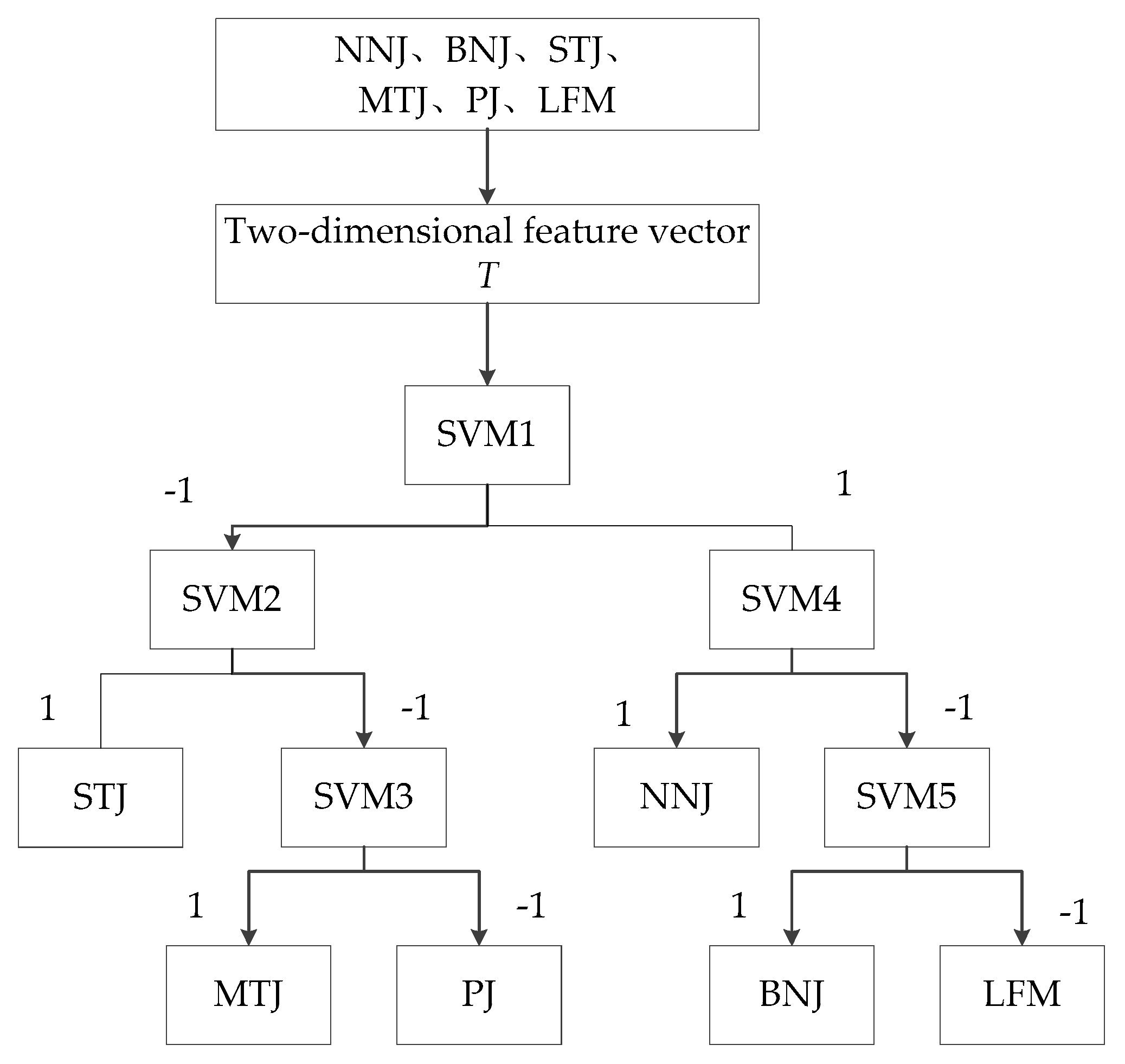
4.1. SVM Classifier Design

SVM has many advantages in solving small samples and nonlinear problems. For example, when learning, it can converge to the global best and can avoid the local minimum problem. Moreover, SVM is based on a complete statistical learning theory and the principle of minimum structural risk, which can obtain improved promotion ability. The SVM algorithm was originally designed for two classification problems. When dealing with multi-classification problems, an appropriate multiclass classifier must be constructed. At present, the methods of constructing SVM multiclass classifiers can be roughly divided into two categories:
(1)
Direct method: This method is directly modified on the objective function, and the parameter solution of multiple classification surfaces is merged into an optimization problem. Then, the optimization problem is solved “one-time” to achieve multi-class classification. This method seems simple, but its computational complexity is relatively high, and it is difficult to implement. Thus, it is only suitable for small problems.
(2)
Indirect method: This method is used to realize the construction of multiple classifiers by combining multiple two classifiers. The more common methods now include the one-to-one method, the one-to-many method, and BT-SVM.
For the K classification problem, the one-to-one method needs to construct a sub-classifier between any two types of samples in the K class. Therefore, a total of K sub-classifiers need to be constructed, and the type of samples to be classified is determined by voting in the recognition stage; the one-to-many method constructs sub-classifiers between any one of the K classes and the remaining ( K 1 ) class samples, and thus a total of C K 1 = K sub-classifiers need to be constructed; the binary tree method is used to construct a sub-classifier for each node in accordance with the structure of the binary tree, and hence only ( K 1 ) sub-classifiers can be constructed to classify the K -type samples. Finally, the classification process only needs to follow one path in the binary tree structure to complete the classification. The analysis shows that the number of sub-classifiers to be constructed by the BT-SVM method is the smallest among the above methods, and its classifier training speed and recognition speed are faster. Therefore, the BT-SVM method is selected to design multiple classifiers.

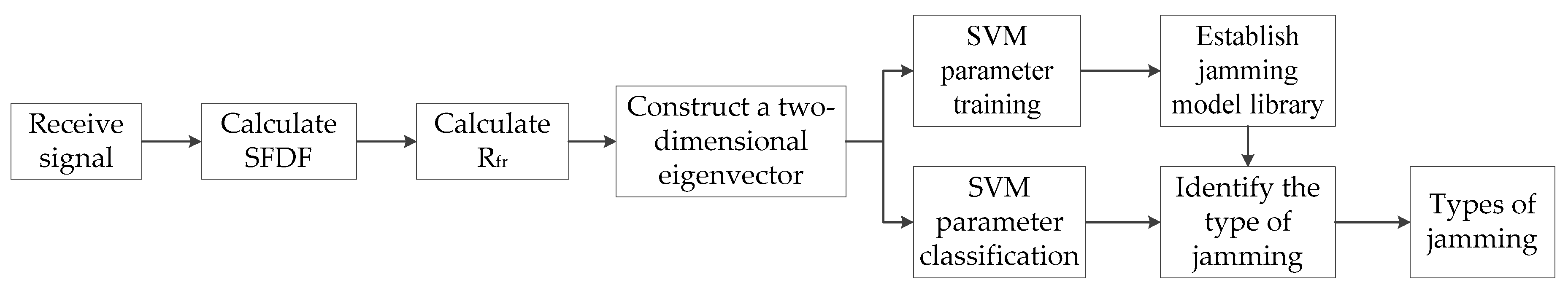
4.2. Jamming Recognition Process

The steps of the jamming recognition algorithm are as follows:
  • The received signal y ( n ) takes the DFT and calculates its normalized spectrum. Equations (13), (16), and (17) are used to obtain the SFDF, which is used as a characteristic parameter of different jamming patterns.
  • Equations (19) and (20) are used to calculate R fr , which is used as another characteristic parameter of different jamming patterns.
  • Two-dimensional feature vectors T = [ D , R fr ] are constructed with different jamming patterns.
  • The two-dimensional feature vector T with different jamming patterns is used as a sample to establish the SVM classifier, and then the BT-SVM classifier is used for classification.
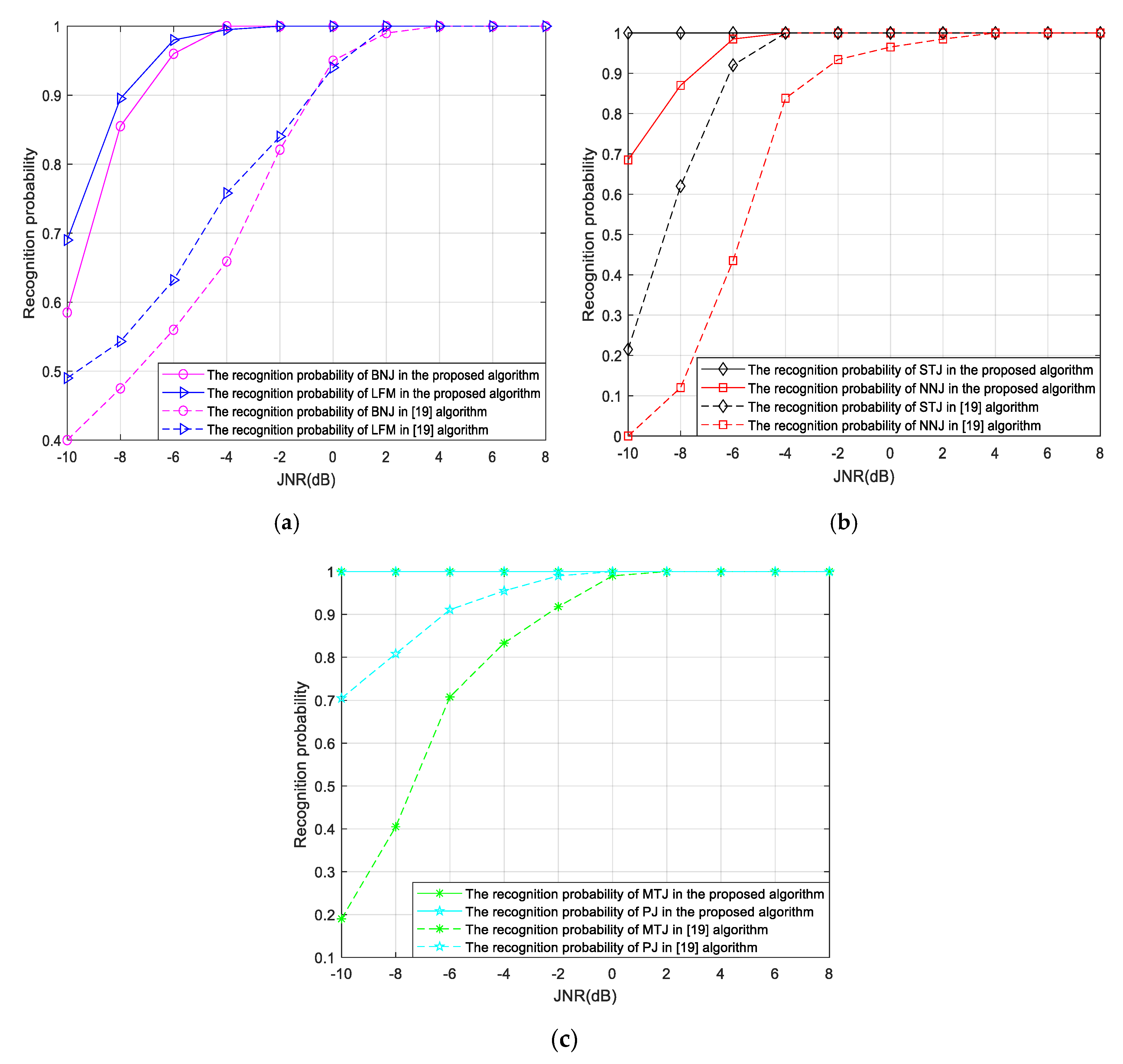
It can be seen from Figure 4 that the boundaries between the six jamming patterns are evident, and the BT-SVM classifier can be used for classification. The jamming identification process is shown in Figure 6. In the training process of the BT-SVM classifier, the feature vectors T = [ D , R fr ] of six types of jamming patterns are first extracted. SVM1 uses the feature vector T of all jamming patterns as the training set, and uses the SFDF as the main classification basis. It divides six types of jamming into two sets, STJ, MTJ, and PJ are in one set, marked as −1; the remaining NNJ, BNJ and LFM are contained in another set, marked as 1. Then, the feature vector T of STJ, MTJ, and PJ is used as the training set to construct the classifier SVM2. It uses the SFDF of the jamming signal as the main classification basis, and divides MTJ and PJ into a set marked as −1, and separates STJ into a set to complete the identification of STJ. For the two jamming patterns of MTJ and PJ, constructing the classifier SVM3 can distinguish between them. SVM4 uses the feature vector T of NNJ, BNJ, and LFM as the training set, and uses the two-dimensional features of the three jamming patterns as the classification basis. It divides the three types into two sets, one contains BNJ and LFM, represented by label 1, and the other contains only one NNJ, represented by label −1, and, at this point, NNJ can be identified. Finally, SVM5 uses R fr as the main classification basis to distinguish BNJ from LFM; thus, the recognition of BNJ and LFM is realized.
In the recognition process, according to the recognition process of the BT-SVM multi-classifier, the feature vector T of the jamming signal only needs to follow one path in the BT-SVM structure to complete the classification.

5. Simulation

In the simulations, each jamming pattern randomly generates 400 samples, of which 200 samples are used as the training set of BT-SVM, and the remaining 200 samples are used as the test set. The sampling frequency is f s   =   20   MHz , and the parameters of various types of jamming are shown in Table 1.
This study compares the new algorithm with the algorithm proposed in [19]. The algorithm in [19] extracts the box dimension and L-Z complexity feature C of various features to form a two-dimensional feature vector and then uses BT-SVM for classification. Figure 7 shows the comparison of the recognition rates of the two algorithms under the same simulation conditions. When JNR = −10 dB, the worst recognition effect of the new algorithm for the six kinds of interference is BNJ, and its recognition rate is approximately 58%. However, at this time, the recognition algorithm in [19] has a recognition rate of 40% for BNJ. Under the same JNR, the recognition rate of the recognition algorithm in [19] for NNJ is approximately 0%, whereas the recognition rate of the new algorithm is approximately 69%. When JNR = −6 dB, the recognition rates of NNJ, BNJ, and LFM in the algorithm proposed in this study all reach more than 95%, whereas the recognition rate of the algorithm in [19] is less than 65%. Under the same JNR, the recognition rate of new algorithms for STJ, MTJ, and PJ is 100%. However, the recognition rate of the algorithms STJ and PJ of [19] is approximately 92%, and the recognition rate of MTJ is only 73%. The algorithm proposed in this study has a recognition rate of 80% for the six types of interference when JNR = −8 dB, whereas the algorithm in [19] can achieve this recognition rate when JNR = −2 dB. Therefore, the algorithm proposed in this study has a gain of 6 dB compared with the algorithm in [19], which greatly improves the recognition rate under low JNR conditions.
Under the same circumstances, 20 Monte Carlo simulations are performed on the two algorithms. Table 2 shows the configuration parameters of the simulated device. The time-consuming comparison of the two algorithms is shown in Table 2. Both algorithms use the BT-SVM classifier, and only the extracted features are different; thus, only the time used to extract the simulation experiment parameters is compared. Table 3 shows that compared with the algorithm in [19], the proposed algorithm shortens the time for feature parameter extraction; thus, the proposed algorithm has better real-time performance.

6. Conclusions

Aiming at the six kinds of jamming recognition problems often faced in UAV data link FH systems, this study proposes a jamming recognition algorithm based on SFD and energy concentration property. The SFDF and R fr of the jamming signal are first extracted to form a two-dimensional feature parameter vector. Then, in accordance with the characteristics of the extracted feature parameters, the BT-SVM classifier is designed to complete the classification and recognition of the jamming signal. Finally, the recognition performance of the proposed method is verified by simulation and compared with the jamming recognition algorithm based on fractal box dimension and L-Z complexity in [19]. The simulation results show that the recognition performance and recognition speed of the proposed method are better than the method in [19], and the advantage is more evident when the JNR is low.

Author Contributions

R.X. conceived and designed the experiments. J.L. performed the experiments, analyzed the data and wrote the paper. H.T. contributed to the revisions and the discussion of the results. All authors have read and agreed to the published version of the manuscript.

Funding

This paper was supported in part by the Technology Development Project of the China Research Institute of Radiowave Propagation (No. JW2019-114), the National Natural Science Foundation of China (No. 61873070), Heilongjiang Provincial Natural Science Foundation of China (No. LH2020F018), and the Heilongjiang Province Key Laboratory of High Accuracy Satellite Navigation and Marine Application Laboratory (No. HKL-2020-Y03).

Conflicts of Interest

The authors declare no conflict of interest.

References

  1. Pazmiño, W.M.; Olmedo, A.J.; Redrován, D.V. Analysis and determination of minimum requirements for a data link communication system for unmanned aerial vehicles-UAV’s. In Proceedings of the 2016 IEEE Ecuador Technical Chapters Meeting (ETCM), Guayaquil, Ecuador, 12–14 October 2016; pp. 1–6. [Google Scholar]
  2. Li, Y.C.; Wang, G.H.; Sun, D.X.; Guan, C. Technique against self-protection repeating track false-target deceptive jamming for radar. J. Syst. Eng. Electron. 2015, 37, 1242–1248. [Google Scholar] [CrossRef]
  3. Jung, H.; Van Nguyen, B.; Song, I.; Kim, K. Design of Anti-Jamming Waveforms for Time-Hopping Spread Spectrum Systems in Tone Jamming Environments. IEEE Trans. Veh. Technol. 2020, 69, 728–737. [Google Scholar] [CrossRef]
  4. Zhou, B.; Kong, D.; Geng, H.; Dai, H.; Wang, J. A Design of Cognitive Anti-jamming System in Complex Environment. In Proceedings of the 2019 Cross Strait Quad-Regional Radio Science and Wireless Technology Conference (CSQRWC), Taiyuan, China, 18–19 July 2019; Institute of Electrical and Electronics Engineers (IEEE): New York, NY, USA, 2019; pp. 1–3. [Google Scholar]
  5. Mitola, J.; Maguire, G. Cognitive radio: Making software radios more personal. IEEE Wirel. Commun. 1999, 6, 13–18. [Google Scholar] [CrossRef] [Green Version]
  6. Geirhofer, S.; Sun, J.Z.; Tong, L.; Sadler, B.M. Cognitive frequency hopping based on interference prediction. Mob. Comput. Commun. Rev. 2009, 13, 49–61. [Google Scholar] [CrossRef]
  7. Han, G.; Xiao, L.; Poor, H.V. Two-dimensional anti-jamming communication based on deep reinforcement learning. In Proceedings of the 2017 IEEE International Conference on Acoustics, Speech and Signal Processing (ICASSP), New Orleans, LA, USA, 5–9 March 2017; Institute of Electrical and Electronics Engineers (IEEE): New York, NY, USA, 2017; pp. 2087–2091. [Google Scholar]
  8. Hasan, S.; Yu, D.Y. Algorithm and experimentation of frequency hopping, band hopping, and transmission band selection using a cognitive radio test bed. In Proceedings of the 2014 23rd Wireless and Optical Communication Conference (WOCC), Newark, NJ, USA, 9–10 May 2014; pp. 1–5. [Google Scholar]
  9. Fan, G.W.; Yu, B.G.; Chao, L.; Deng, Z. Design of interference recognition and classification filter of satellite navigation electromagnetic environment. Syst. Eng. Electron. 2014, 36, 234–238. [Google Scholar] [CrossRef]
  10. Yang, X.M.; Tao, R. Automatic Identification of Interferences in Direct Sequence Spread Spectrum Communication System. Acta Armamentarii 2008, 29, 1078–1082. [Google Scholar] [CrossRef]
  11. Zhou, Z.D.; Chen, Z.L.; Gao, X.J.; Yao, A. Automatic Recognition of Interference Type in UAV Data-link. Comput. Meas. Control 2015, 23, 3780–3782. [Google Scholar] [CrossRef]
  12. Meng, X.-Y.; Tao, R.; Jia, L.-N. An Intelligent Anti-jamming Frequency Hopping System. In Proceedings of the 2010 First International Conference on Pervasive Computing, Signal Processing and Applications, Harbin, China, 17–19 September 2010; Institute of Electrical and Electronics Engineers (IEEE): New York, NY, USA, 2010; pp. 1053–1056. [Google Scholar]
  13. Fang, F.; Li, Y.G.; Niu, Y.T.; Wang, Y.T. Interference signal recognition based on decision tree algorithm. Commun. Technol. 2019, 2617–2623. [Google Scholar] [CrossRef]
  14. Liang, J.D.; Cheng, Y.F.; Du, Y.; Wang, P. The Research of Interference Recognition Technology Based on the Joint Multi-dimensional Features. J. Signal Process. 2017, 33, 1609–1615. [Google Scholar] [CrossRef]
  15. Wang, G.S.; Ren, Q.H.; Jiang, Z.G.; Liu, Y.; Xu, B. Jamming classification and recognition in transform domain communication system based on signal feature space. Syst. Eng. Electron. 2017, 39, 1950–1958. [Google Scholar] [CrossRef]
  16. Wang, G.H.; Bai, J.; Zhang, X.Y.; Sun, D. Detection and classification algorithm of suppression interference based on characteristic differences of FRFT domain. J. Beijing Univ. Aeronaut. Astronaut. 2018, 44, 1124–1132. [Google Scholar] [CrossRef]
  17. Huang, H.; Wu, L.M.; Bao, L.L.; Liu, W. Jamming recognition scheme based on fractal box dimension and Wavelet packet energy. J. Air Force Early Warn. Acad. 2014, 28, 422–426. [Google Scholar] [CrossRef]
  18. Zhang, X.Z. An Interference Pattern Recognition Method Based on Complexity Measure. J. Heze Univ. 2013, 35, 30–36. [Google Scholar] [CrossRef]
  19. Niu, Y.; Cheng, Y.; Chen, J. Jamming pattern recognition based on complexity measure. In Proceedings of the 2010 3rd International Congress on Image and Signal Processing, Yantai, China, 16–18 October 2010; Volume 8, pp. 3596–3600. [Google Scholar] [CrossRef]
  20. Sevcik, C. On fractal dimension of waveforms. Chaossolitons Fractals 2006, 28, 579–580. [Google Scholar] [CrossRef]
  21. Tao, R.; Deng, B.; Zhang, W.-Q.; Wang, Y. Sampling and Sampling Rate Conversion of Band Limited Signals in the Fractional Fourier Transform Domain. IEEE Trans. Signal Process. 2007, 56, 158–171. [Google Scholar] [CrossRef]
  22. Chen, X.L.; Guan, J.; Liu, N.B.; He, Y. Adaptive filtering algorithm for LFM signal and performance analysis based on FRFT. Mod. Radar 2010, 32, 48–53. [Google Scholar] [CrossRef]
  23. Shen, P. Research on Interference Recognition Technology in Frequency Hopping Communication System; Xidian University: Xi’an, China, 2018. [Google Scholar]
Figure 1. Block diagram of the unmanned aircraft vehicle frequency hopping (UAV FH) system.
Information 11 00520 g001
Figure 2. Sevcik fractal dimension from the frequency domain (SFDF) of six kinds of interference changes with the increase in jamming-to-noise ratio (JNR).
Information 11 00520 g002
Figure 3. Changes of broadband noise jamming (BNJ) and linear frequency modulation jamming (LFM) as JNR increases.
Information 11 00520 g003
Figure 4. Characteristic distribution diagram of six types of jamming.
Information 11 00520 g004
Figure 5. Block diagram of interference recognition based on two-dimensional features.
Information 11 00520 g005
Figure 6. Jamming recognition process based on two-dimensional features.
Information 11 00520 g006
Figure 7. Recognition rate of the algorithm proposed in this study and the algorithm in [19]. (a) Recognition rate of broadband noise jamming (BNJ) and linear frequency modulation jamming (LFM); (b) Recognition rate of narrowband noise jamming (NNJ) and single-tone jamming (STJ); (c) Recognition rate of multi-tone jamming (MTJ) and pulse jamming (PJ).
Information 11 00520 g007
Table 1. Jamming signal parameters.
Jamming TypesJamming Parameters
NNJCenter frequency2.5 MHz
Bandwidth10% (FH bandwidth)
BNJBandwidth100% (FH bandwidth)
STJJamming frequency5 MHz
MTJJamming frequency{3, 4, 5, 6, 7, 8, 9, 10} MHz
PJDuty cycle10%
LFMFrequency sweep range2–8 MHz
Table 2. Simulation device configuration parameters.
Windows VersionSystem
Windows10ProcessorInstalled memory (RAM)System type
Intel Core i5-1035G1 CPU16.0 (GB)64-bit operating system
Table 3. Time-consuming comparison of feature extraction.
AlgorithmFeature Extraction Time
Proposed algorithm73.538922 s
Algorithm in [19]107.171106 s
Publisher’s Note: MDPI stays neutral with regard to jurisdictional claims in published maps and institutional affiliations.

