Telecommunication Systems for Small Satellites Operating at High Frequencies: A Review

Jet Propulsion Laboratory, California Institute of Technology, Pasadena, CA 91109, USA
Information 2020, 11(5), 258; https://0-doi-org.brum.beds.ac.uk/10.3390/info11050258
Submission received: 21 February 2020
/
Revised: 28 April 2020
/
Accepted: 30 April 2020
/
Published: 8 May 2020
(This article belongs to the Special Issue Satellite Communication at Ka and Q/V Frequency Bands)
Abstract
:Small Satellites and in particular CubeSats are becoming extremely popular platforms with which to perform space research. They allow for rapid prototyping with considerable cost savings with respect to traditional missions. However, as small satellite missions become more ambitious in terms of destinations to reach (from Low Earth Orbit to interplanetary) and in terms of the amount of data to transmit, new technologies need to be developed to provide adequate telecommunication support. This paper aims to review the telecommunication systems that have been developed at the Jet Propulsion Laboratory for some of the most recent CubeSat missions operating at different frequency bands: ASTERIA (S-Band), MarCO (X-Band and UHF) and ISARA (Ka-Band and UHF). For each of these missions: the telecommunication challenges and requirements are listed; the final system design is presented; the characteristics of the different hardware components are shown; and the lessons learned through operations are discussed.
1. Introduction
Small satellites and CubeSats are currently being developed by space agencies, universities and private companies. They allow for rapid prototyping and testing with limited cost with respect to larger spacecraft. Over the course of this last decade, many advances have occurred in the technologies for small satellites. CubeSats are now more power capable than in the past; they can be equipped with propulsion systems to perform maneuvers, and they can achieve fine pointing.
In the field of telecommunications, many developments have occurred to allow CubeSats and small satellites to relay higher volumes of data, to communicate from farther points in the solar system such as Mars, and to enable radiometric data collection for navigational functionalities. Specifically, the Jet Propulsion Laboratory (JPL) has been involved in the design, implementation and operation of many CubeSat missions either as the prime organization or in partnership with others.
In this paper, we are reviewing three of these missions (ASTERIA, MarCO and ISARA) focusing on the telecommunication system. The paper is organized as follows: Section 2 is dedicated to ASTERIA, Section 3 to MarCO and Section 4 to ISARA. Section 5 presents a summary. For each of these missions: the telecommunication challenges and requirements are listed; the final system design is presented; the characteristics of the different hardware components are shown; the lessons learned through operations are discussed.
2. ASTERIA
ASTERIA [1] (Arcsecond Space Telescope Enabling Research in Astrophysics) is a 6U CubeSat designed, integrated, and operated by JPL to demonstrate high-precision pointing control and thermal control, and to conduct photometric measurements of bright, nearby stars to seek transiting exoplanets. The project started in 2014 and ASTERIA was launched in August 2017 as pressurized cargo on a Commercial Resupply Services mission to the International Space Station (ISS). ASTERIA deployed into low-Earth orbit in November 2017 and in February 2018 completed the technology demonstration objectives planned for the 90-day prime mission. Since then, ASTERIA has been performing an extended mission to search for exoplanets and obtain additional operational spacecraft data. As of this writing, ASTERIA has been operating in space for over 2 years, until December 2019 when it lost contact.
2.1. Telecommunication Requirements and Design
ASTERIA was required to use the S-Band frequency as it was initially planned to use the Near Earth Network (NEN) stations as the ground station for this project. However, as the design progressed the team moved from the decision of using the NEN stations to use the 21 m antenna at Morehead State University (MSU) which is now part of the Deep Space Network (DSN) and also operating at S-Band.
Additionally, the telecommunication system was required to be CCSDS (Consultative Committee for Space Data Systems) compatible and to deliver a data volume of approximately 1 Gb per day. This translated into a data rate requirement of approximately 1 Mbps considering the availability of the ground station and the average duration of the contacts (approximately 8 min, and 2 contacts per day). In terms of sizing, all the components needed to be compatible in mass and power with the typical CubeSat form factor.
Given all the requirements and constraints, the system was designed as a full duplex S-band system (Figure 1) including one S-band transceiver assembly and two low gain antennas (LGA). The transceiver assembly includes a switch to select among two possible antennas, a diplexer to separate uplink and downlink paths, a solid state power amplifier (SSPA) for the downlink, and a low noise amplifier (LNA) for the uplink. The two antennas are identical S-band patch antennas which operate at both transmitting and receiving frequencies and are placed on opposite sides of the spacecraft to maximize coverage.
The data rates used are 10 kbps and 1 Mbps in downlink, and 4 kbps and 32 kbps in uplink. The low data rates are designed for acquisition and safe modes, while the high data rates are for normal operations.
2.2. Hardware Characteristics
The hardware components used for the ASTERIA telecommunication systems have been procured through Vulcan Wireless Inc.
The patch antennas (Figure 2, Table 1) are functional in full duplex mode over the entire Near Earth Frequency range (2.0–2.11 GHz in uplink and 2.2–2.3 GHz in downlink). They have a peak gain of 7 dBi in downlink and 6 dBi in uplink and a half power beamwidth of approximately 70 degrees. They are right-hand circularly polarized, and present an impedance of 50 Ohm. The antennas are compatible with the CubeSat Form factor in size (82 mm × 82 mm × 12 mm) and mass (76 g). Pattern and additional characteristics are shown in [1].
The transceiver (Figure 3) is a full duplex radio that receives a direct carrier BPSK-modulated signal at either 4 kbps or 32 kbps while transmitting a direct carrier OQPSK-modulated signal at either 10 kbps or 1 Mbps. The transceiver assembly has a single interface with the command and data handling (C&DH) for radio telemetry and an interface for a 28 Volt line connected directly to the ASTERIA power system. In terms of frequencies, it is designed as a Software Defined Radio to operate in the entire Near Earth Frequency band. Hence, it can be reprogrammed to transmit at any frequency in the 2.2–2.3 GHz and to receive at any frequency in the 2.0–2.11 GHz range. This feature has been critical for the design of the ASTERIA telecommunication system. Due to the tight schedule, the engineers had to design the system while simultaneously filing for a telecommunication license. As a result, it was important to select a radio that was robust with respect to changes in frequency within the band. The transceiver features different coding options from Reed Solomon to convolutional, has a sensitivity threshold of −126 dBm, and it is compatible with the CubeSat form factor in size is (82 × 82 × 38 mm), mass (400 g), and power consumption (3.5 W in receive mode and 8.5 W in full duplex for 1 W of radiated power). Additional information and performance metrics for the transceiver can be found in [1].
2.3. Operations
Spacecraft deployment from the ISS occurred nominally at 12:25:01 UTC on 20 November 2017. Because ASTERIA was deployed by itself, the identification by the JSpOC (Joint Special Operations Command) was relatively quick, and a TLE (Two Line Element) set was available within 12 h of deployment.
The acquisition for ASTERIA was particularly challenging due to the following aspects [1]:
- ASTERIA was relying on only one ground station.
- The MSU station has a very small beamwidth, as a result of having such a large dish (21 m).
- The ASTERIA antennas are regulated by a switch, so there is no omnidirectional coverage of the spacecraft.
- The radio does not support a beacon mode, and it needs to receive an uplink signal before it can activate the downlink.
- The radio was on a duty cycle for which it was on for 30 min and off for 10 min, due to power consumption constraints.
As a result of all these challenges, acquisition was deemed a difficult task and the operations team was planning to dedicate several passes just to acquire the signal. Luckily, the system worked even better than expected and the signal from ASTERIA was acquired at the very first available opportunity, which was the second time that the spacecraft was in visibility with the ground station from the moment of deployment. The team later realized from telemetry post-processing that the duty cycle had the radio off during the first visibility opportunity.
Following first acquisition, the operations team performed radio checkout operations which entails ensuring the health of the telecom subsystem by monitoring the key telemetry parameters and the spectrum, and performed a switch to high data rates to verify functionality in every configuration.
The key telecommunication telemetry parameters provided in the ASTERIA real-time telemetry (with values updated every 28 s) are the following: antenna selection (1 or 2 depending on which particular antenna the spacecraft is using to communicate), radio temperature of the Memory Signal Processor (flight allowable temperature range is −25 to 60 deg C), radio lock (1 if the radio is locked, zero otherwise), radio oscillator temperature (the flight allowable range for this sensor is −25 to 60 deg C), and radio voltage of the power amplifier (normal range is between 3 and 5 V). Examples of the values can be found in [1]. For the first few passes, telemetry was nominal, so that the operation activity lead allowed us to command the spacecraft to transition into high data rate modes. It took a couple of passes to perform this operation, as the rotation of the spacecraft was affecting the antenna gain and the link performance. Finally, at the second trial, the change of data rates was successful. Operations in the following days were focused on troubleshooting some issues identified during these early operations. Specifically:
- The spectrum was shifting in frequency faster than expected due to both Doppler and spacecraft rotation.
- Downlink Eb/N0 was lower than expected due to
- (a)
- The high level of uplink power was saturating the ASTERIA receiver.
- (b)
- The rotation of the spacecraft was affecting the antenna pointing.
- (c)
- Though not known at the beginning of the operations, the LNA at the ground station was failing. This failure was discovered during the extended mission phase. Replacing the LNA resulted in a 3 dB increase in the received Eb/N0).
The fixes implemented were the following:
- The downlink receiver bandwidth was increased by a factor of 10 to reduce the loss of lock.
- The uplink signal from the ground station was reduced by approximately 9 dB in order to avoid receiver saturation.
- The spacecraft pointing system was commanded to point the antenna at the ground station to limit the loss of contact due to spacecraft rotation.
Results showed that all three fixes improved the length and quality of the telecommunication passes. Specifically, passes duration moved from 2–3 min to 8 min and the Eb/N0 at high data rates moved from an initial value of 10 dB to 18 dB at high data rates (21 dB after the ground station LNA replacement in August 2018).
3. MarCO
The MarCO (Mars CubeSat One) mission [2] is composed of two twin CubeSat designed to perform a Mars flyby and to relay data during the Entry, Descent and Landing (EDL) phase for the InSight (Interior Exploration using Seismic Investigations, Geodesy and Heat Transport) mission. The two CubeSats were, like ASTERIA, designed, assembled, and operated by JPL. The mission was launched on 5 May 2018, together with the JPL mission InSight. Immediately after launch, MarCO-A and MarCO-B separated from the Atlas V launch vehicle and traveled along their own trajectories to Mars. Once there, they supported the InSight mission by receiving the UHF signal from the lander, by decoding it and re-encoding it into an X-Band signal that was then forwarded directly to the Deep Space Network (DSN) antennas during the EDL phase (26 November 2018). After the EDL phase, both MarCO spacecraft completed a flyby of Mars and remained active until some time in January 2019, when it was reported that they both lost contact [3].
3.1. Telecommunication Requirements and Design
In order to perform its primary mission, the MarCO spacecraft needed to be compatible with the Deep Space Network antennas and with the signal transmitted from the Insight spacecraft. Hence, it was required to use X-Band frequency for the Direct to Earth (DTE) link, and UHF frequency for the relay link from InSight. In terms of data rate, given that InSight was transmitting UHF data at 8 kbps, the relay system on the MarCO spacecraft was also required to function at the same data rate on the DTE link. The data rate requirement significantly drove the design of the hardware, especially for the high gain antenna. Additionally, the spacecraft were both supposed to navigate to Mars with their own trajectory, which implied that the radio had to be equipped with navigation functionalities to allow for ranging and Doppler estimation.
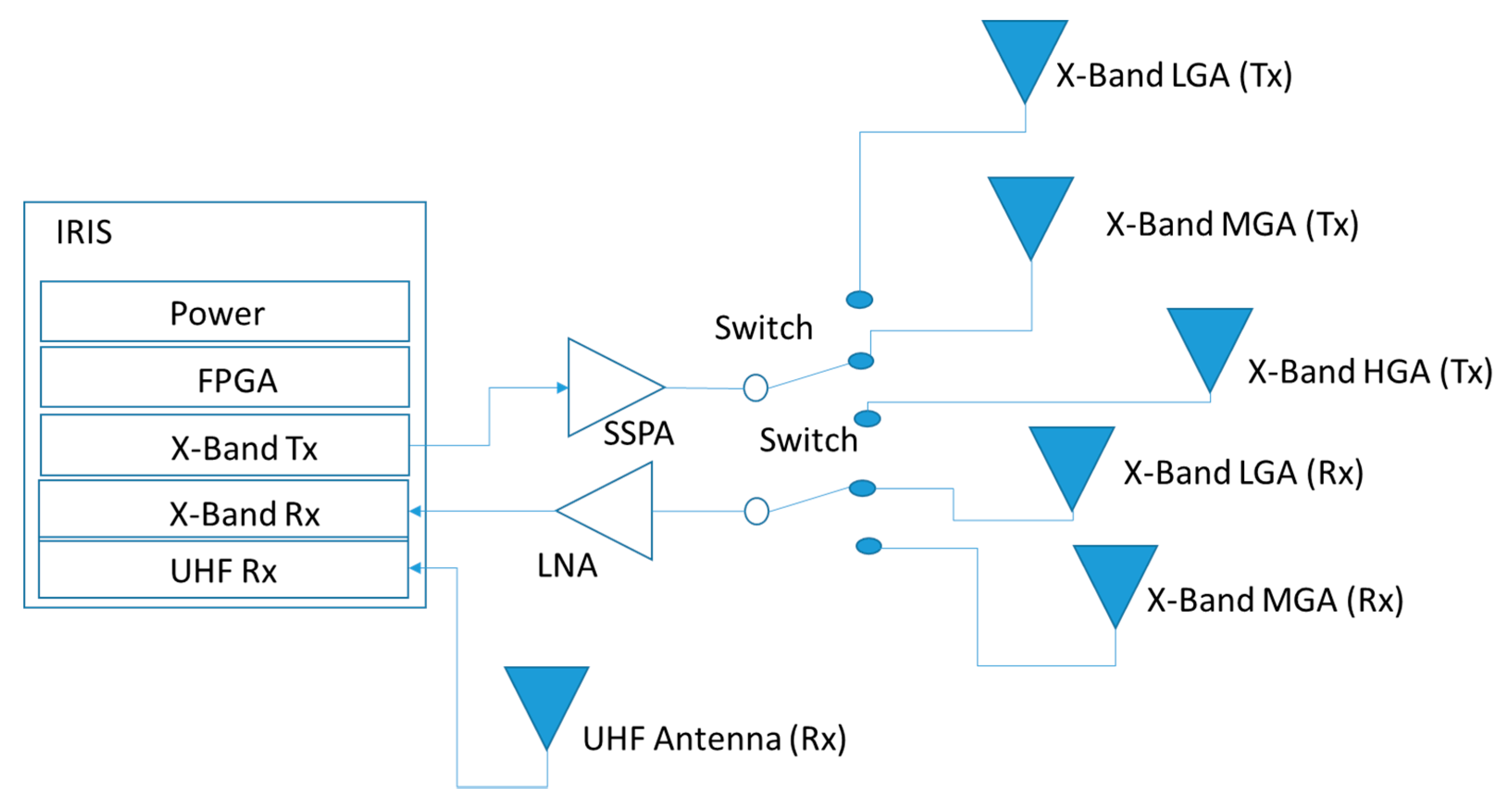
Given these requirements, the system was designed with a unique radio, the Iris transponder that included a UHF receiver, all the X-Band functionalities, and the navigation features. The Iris radio is connected on the X-Band receiving path to a low noise amplifier (LNA) which is connected to one low gain patch antenna and one medium gain patch antenna array for X-Band uplink functions to the DSN. On the transmitting side, the Iris radio is connected to the solid state power amplifier (SSPA) which has three antenna ports and it is connected to a low gain patch antenna, a medium gain patch antenna array and an high gain antenna reflectarray, respectively. For the UHF, a loop antenna is connected to the Iris UHF receiver. A blog diagram is shown in Figure 4. Both the reflectarray and the loop antenna are deployable antennas.
The X-Band data rates mode used are 62.5 bps and 1000 bps for uplink, while for downlink the mission used a variety of data rates from 62.5 bps up to 8000 bps. At UHF, the data rate used was 8000 bps and the system was functioning in receiving mode only without any transmitting capabilities.
3.2. Hardware Characteristics
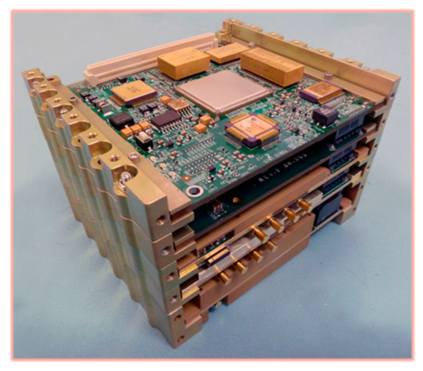
The main component of the telecommunication system for the MarCO mission is the Iris radio. Originally designed at JPL for the NSPIRE (Interplanetary NanoSpacecraft Pathfinder In Relevant Environment) mission [4], the Iris radio aims to be a CubeSat compatible radio to support not only telecommunication but also navigation functionalities for interplanetary CubeSat and small satellite missions. Iris has a modular design with interchangeable boards to allow interoperability at different frequencies. For the MarCO mission, the Iris radio (Figure 5) was composed of five slices: a power slice, an FPGA slice for the major digital signal processing functions, a transmitting slice at the X-Band, a receiving slice at X-Band and a receiving slice at UHF. Iris radio is a software defined radio which allows flexibility in the selection of the central frequency which is again important due to the fact that in many of the CubeSat missions the development schedule is such that the frequency license application is filed concurrently with the development of the telecommunication system. The Iris radio at X-band is compatible with both the Near Earth and Deep Space frequency ranges (8400–8500 MHz for downlink, 7145–7235 MHz for uplink), and it performs multiple navigation functions: ranging, Doppler, and Delta-Differential One-way Ranging (DDOR). It can operate in both non-coherent and coherent modes with a turn-around ratio of 880/749. The noise factor of the receiver is variable depending on the environmental conditions but it does not exceed 5 dB. In downlink, it allows for either subcarrier or direct carrier BPSK modulation with multiple encoding options: Reed Solomon (255,223), convolutional (K = 7, r = 1/2), Turbo ½, Turbo 1/3 and Turbo 1/6. Downlink data rates range from a minimum of 62.5 bps to a maximum of 256 kbps. The uplink signal from DSN is uncoded PCM/PSK/PM and it ranges from a minimum of 62.5 bps to 2 kbps. The radio weighs approximately 1200 g [4] and consumes up to 30 W of power in full duplex mode (including the SSPA power). The UHF slice allows receiving functionalities in the 390–405 MHz band.
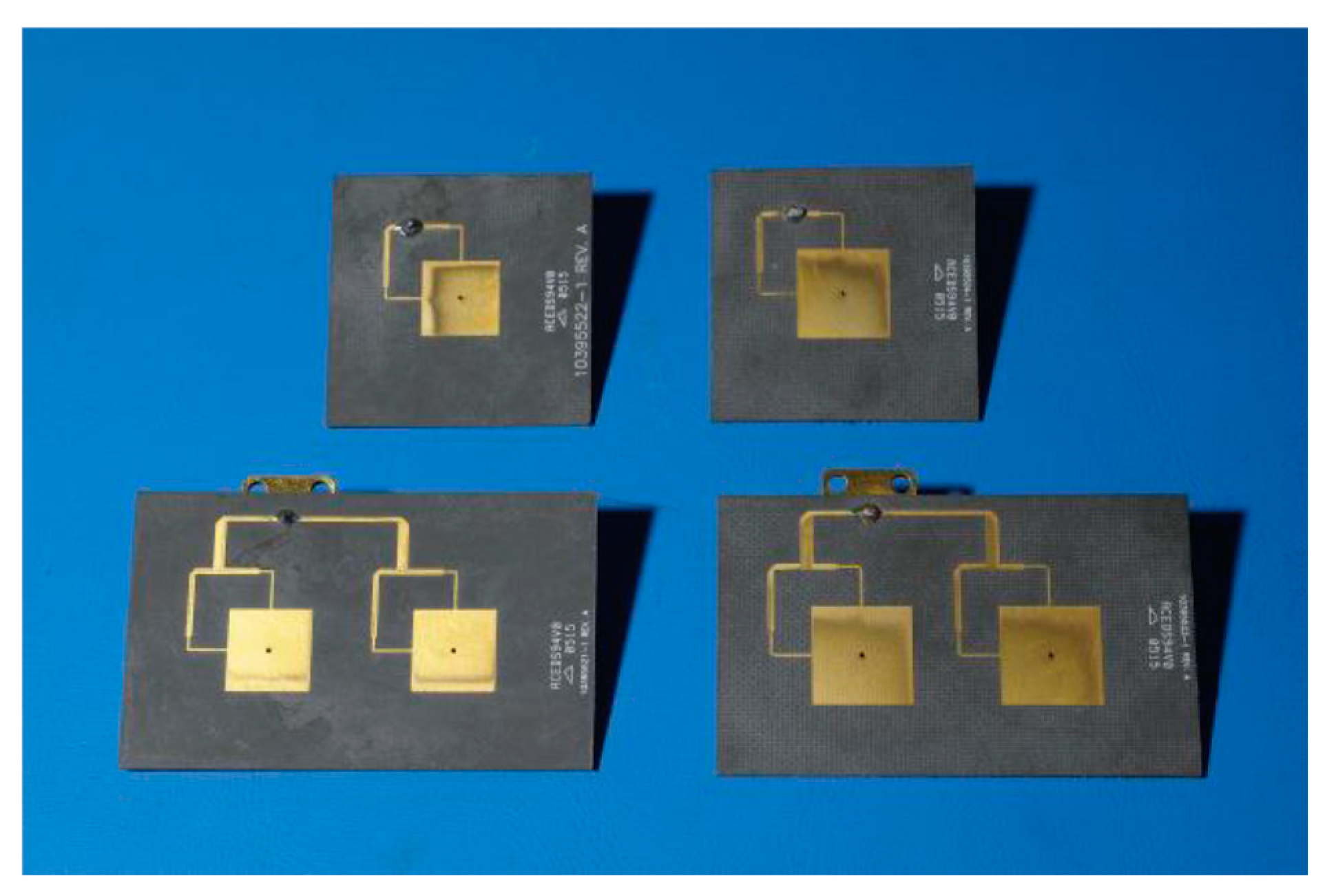
The X-Band antennas (Figure 6 and Figure 7, Table 2) used for the MarCO mission are: low gain patch antennas, medium gain patch antenna arrays, and a high gain antenna. The LGA (both transmit and receive) consist of dual-edge-fed circularly polarized patch antennas. The two RHCP patch antennas are printed on RT Duroid 5880 [6]. In terms of performance, the antennas are designed to operate in the entire Near Earth and Deep Space frequency ranges, with a peak gain of 6 dBi and a 3 dB beamwidth of approximately 60°. The MGA antennas consist of 2 × 1 patch arrays and they are used to slightly increase the gain (especially for operations around) while still maintaining the beamwidth wide enough to minimize the need for fine pointing. Furthermore, these antennas are designed for the entire X-Band range and they provide a peak gain of approximately 9 dBi with a 3 dB beamwidth of 20°. The mass of the LGA and MGA is approximately 15 g each.
The high gain antenna (Figure 7) [7] is designed based on the reflectarray technology which uses, instead of a more traditional deployable parabola, a flat, reflecting surface that rely on a simple mechanical deployment with spring-loaded hinges. The fully deployed antennas surface for the MarCO HGA is 59.7 × 33.5 cm. At launch, the three reflectarray panels are folded down against the spacecraft body and against each other to form a single 19.9 × 33.5 × 1.25 cm3 panel stack. A 4 × 2 element microstrip patch antenna is used as a feed for the reflectarray antenna. The feed is placed on a thin aluminum plate that has a simple spring-loaded hinge and a small rotary joint. The feed folds underneath the reflectarray. During deployment, the panel assembly rotates away from the bus on the root hinge axis and the feed automatically flips out from the bus and lock into the desired position. The measured gain of the MarCO antenna is 29.2 dBi at 8.425 GHz, and the total mass is approximately 1 Kg.
The UHF antenna (Figure 8) [8] is a deployable loop fed at two locations, with each generating orthogonal linear polarization 90° out of phase with the equal amplitude, thus giving rise to circular polarization. The antenna provides a gain better than 2.5 dB over the ±30° angle in the elevation and azimuthal planes which was sufficient to receive the InSight signal during the EDL phase. All the MarCO antennas (X-Band and UHF) are designed to operate without damage between −55 deg C and +125 deg C.
3.3. Operations
MarCO was launched on May 2018 [5] from the Vandenberg Air Force Base near Lompoc, California. MarCO was deployed after InSight and DSN received the first telemetry from MarCO A at approximately 5.55 am, while data from MarCO-B were received shortly after at 6:05 am [5]. During the first pass, commands were issued to deploy both the X-Band high gain antenna and the UHF loop antenna.
During cruise, uplink functionalities were used to load new command sequences from the ground when desired. In downlink, both spacecraft transmitted mostly health and status data and occasionally pictured taken with the cameras. Navigation was performed using both ranging and Delta-DOR modes. Still during cruise, three main additional activities were performed:
- The gain of the HGA reflectarray antennas were characterized on both spacecraft by pointing the antenna to different attitudes and measuring the received power on the ground
- The bent-pipe EDL mode was tested using the UHF Stanford ground station that simulated the InSight spacecraft and sent signals to both MarCo spacecraft. Both MarCO spacecraft successfully retransmitted the signal to the Deep Space Network
- Both MarCo spacecraft were also received by the Morehead State University ground station, the same as ASTERIA that for the occasion was upgraded with X-Band receiving capabilities.
Once arrived at Mars, both spacecraft successfully supported the EDL of the InSight mission by recording and retransmitting over 600 KB of data (MarCO-A transmitted 694 KB and MarCO-B transmitted 712 KB). This data volume is significant and it is higher than what is conventionally done using Mars relay orbiter assets such as MRO for the same EDL phase [5].
After the EDL phase, both spacecraft completed the flyby of Mars and continued their journey in the solar system transmitting pictures back to Earth until contact was lost (with MarCO-B on 29 December 2018 and with MarCO-A on 4 January 2019) [5].
4. ISARA
ISARA is a CubeSat mission designed to test Ka-Band communication technologies for CubeSat. The spacecraft is a 3U CubeSat carrying a Ka-Band low power transmitter and a Ka-Band reflectarray antenna integrated on the back of the deployable solar panels. Additionally, the spacecraft carries a standard gain antenna and a switch. The standard gain antenna is used to provide a reference gain during operation to allow for the characterization of the performance of the reflectarray [9]. ISARA was launched on 12 November 2017 on the Cygnus Resupply Mission (OA-8) from the Mid-Atlantic Regional Spaceport, Wallops Flight Facility, in Virginia [10]. The spacecraft was deployed from the International Space Station few weeks later and the antenna was successfully deployed right after. Operations occurred over few months during which the pattern of the high gain antenna was characterized [11]. ISARA operated in space for a total of 5 months [12].
4.1. Telecommunication Requirements and Design
The ISARA spacecraft includes two telecommunication systems: a more traditional UHF system developed by Aerospace Corporation to transmit health telemetry and to receive spacecraft commands and the Ka-band telecommunication payload developed by JPL. This article focuses on the Ka-band system only. The requirement for the Ka-band system was to develop a transmit only technology to achieve 100 Mbps in Low Earth Orbit from a 3U CubeSat. The challenge was to develop a technology that would allow to achieve this data rate at the Ka-band and that it was compatible with the form factor of a CubeSat. In terms of compatibility, the Ka-band ground receiver for ISARA was specifically designed for this mission at JPL, so there was no particular need to be compatible with a specific ground network or protocol [12].
Given these requirements, the Ka-Band system (Figure 9) is a very simple design including a low power transmitter connected to a switch that is connected to the reference antenna and the high gain antenna.
4.2. Hardware Characteristics
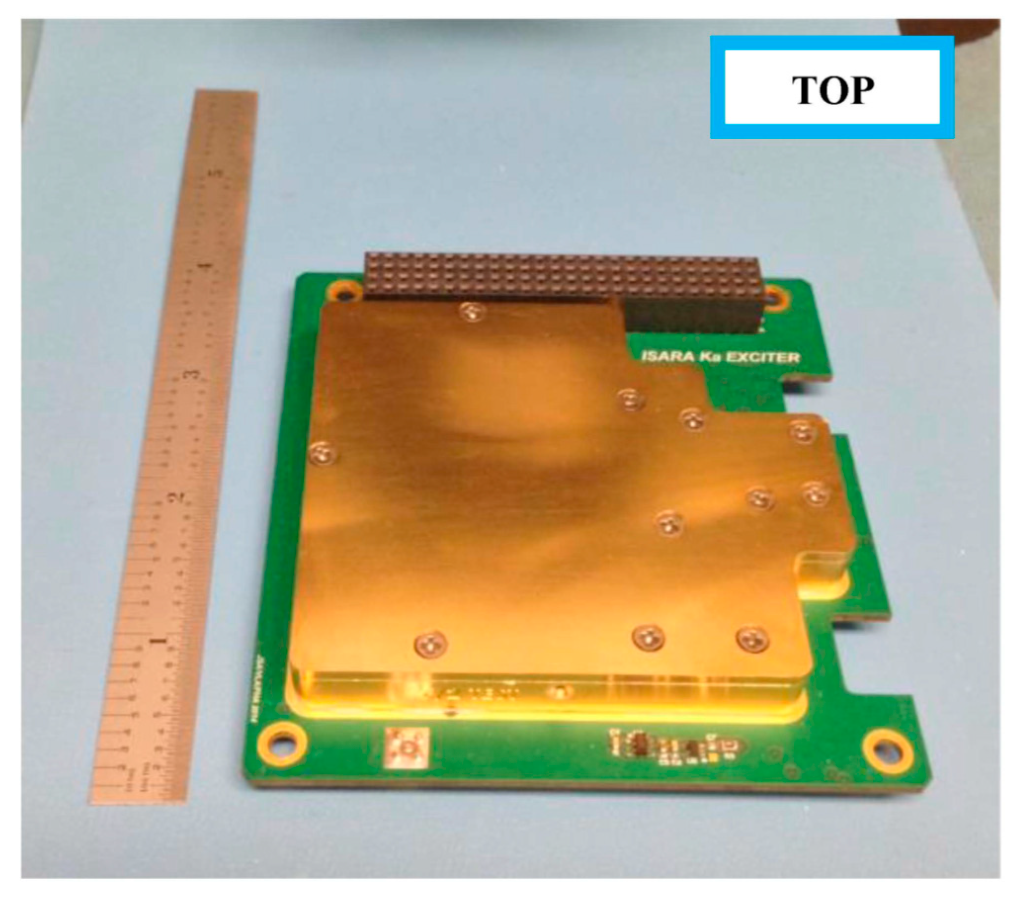
The ISARA transmitter (Figure 10) is at 26 GHz. The tone generator includes a phase locked loop (PLL) frequency multiplier to get to 26 GHz from an on board temperature compensated crystal oscillator (TCXO). The output of the PLL connects to a state power amplifier (SSPA) for a total output power of 27 dBm [13]. The output of the SSPA feeds into a bandpass filter which is connected to an (MMIC) switch which toggles between the high gain and the reference gain antenna as part of the ISARA experiment. Prior to reaching the antenna, a coupler diverts part of the RF power and feeds it into a Schottky detector circuit that provides a telemetry voltage to the spacecraft computer through a buffer. A gold plated aluminum chassis was designed to house the hybrid RF electronics. The transmitter weighs no more than 200 g and consumes no more than 10 W of power [13].
The ISARA reference gain antenna or standard gain antenna (SGA) is a 4 × 4 element microstrip patch array that produces 18.9 dB gain and has a broad antenna beam pattern. The SGA was designed to be insensitive to thermal environment so that it provides a stable and reliable signal comparison to the high gain antenna [12].
The high gain antenna (Figure 11, Table 3) is a reflectarray including three 33.9 × 8.26 cm panels. The ISARA antenna incorporates an array of 24 solar cells (designed and fabricated by Pumpkin Inc, [12]) on the opposite side of the reflectarray, and provides about 24 W of spacecraft power. The feed is mounted on the bus in an offset configuration with a focal length of 27.6 cm and a feed offset of 14.67 cm [14]. The feed design uses a 4 × 4 element microstrip patch array printed on εr = 2.0 substrate and fed by a separate stripline layer. Each patch generates the required circular polarization [14]. The reflectarray performance was characterized at JPL prior to flight by testing in the anechoic chamber. The test showed a very good agreement between predicted and measured performance and the peak gain was measured at 33.5 dBi. Elevation beamwidth was measured at 2.39 degree and azimuth beamwidth at 2.47 degree. The total antenna mass (feed and reflector) is less than 500 g [14].
4.3. Operations
After deployment of the CubeSat from the International Space Station, a five-month mission was used to test the Ka-band antenna. As mentioned before, the spacecraft was also equipped with a UHF telecommunication system which was used to communicate with the UHF ground station owned and operated by Aerospace Corporation [12].
The Ka-band operations were instead performed through a customized Ka-band receiver station developed and operated by the Jet Propulsion Laboratory. The Ka-band station was very simple and designed with mostly off-the-shelf components. It included a 70 cm parabolic dish, low noise amplifier, filter, downconverter to intermediate frequency, filter, amplifier and then an open-loop recorder [12]. The JPL recorder was used to acquire and then measure the Signal-to-Noise-Ratio (SNR) and the gain of the antenna. The HGA gain was measured by rapid switching (~1 Hz) between the HGA and the SGA in a way that was not influenced by atmospheric attenuation, space loss, receiver stability [12]. The CubeSat was also slewed in orbit to allow for measuring of the antenna pattern. The pointing system on board was designed to achieve 0.2 deg precision. The pointing accuracy on the ground was achieved by retrofitting the Ka-Band station with a positioner previously used for the Deep Space Network (total measured was uncertainty 0.8 dB, [12]).
During each measurement session (telecommunication pass), the ground receiver recorded data including HGA and SGA signal level as well as a record of ground station pointing. The UHF telemetry data, transmitted through the UHF channel provided information on the spacecraft antenna pointing which was then used to reconstruct the antenna pattern. These measurements confirmed the antenna gain results obtained by ground testing through a series of conical scans that were used to search for the main beam [12].
5. Comparison
The three missions are very different in terms of goals, mission trajectories, mission lifetime, and environment. Hence, it is hard to compare telecommunication systems developed to satisfy different needs and requirements. However, as a summary, a comparison (Table 4) lists the different telecommunication characteristics for these three missions:
In terms of reliability, it is worth noticing that these systems are not fully redundant as is generally the case for large space missions and commercial satellites. This is the result of the “CubeSat design philosophy”, which is agile in terms of cost and development schedule. That does not mean reliability is not considered, since measures are still taken to minimize failures and to reduce risks. For example:
- The systems are not fully redundant but they have some redundancy in terms of antennas or frequencies used. ASTERIA has a single radio but two antennas which can be used alternatively. MarCO has two receivers (UHF and X-Band), three X-Band transmitting antennas (LGA, MGA, HGA), and three receiving antennas (one at UHF, and two at X-Band). ISARA has an uplink/downlink system at UHF and a Ka-Band downlink.
- Each component was carefully tested at the vendor and at JPL (at the system level for the spacecraft integrated at JPL: MarCO and ASTERIA).
Finally, the value of technical communication cannot be stressed enough. In each of these projects, communication with the vendors and within the different subsystems allowed us to identify issues and components’ idiosyncrasies early on. This allowed the development of procedures to work around and minimize problems, and to maximize the functionality for each of the components during operation.
6. Conclusions
In this paper, a review of the telecommunication systems for three different CubeSat missions is presented. For each of the missions, the main telecommunication requirements and constraints are listed, and the impact on the telecommunication design is discussed. The main telecommunication components are described and lessons learned from performing operations are shown.
The development of telecommunication systems for these three missions and their operational success show that it is possible to use CubeSats to perform certain science investigations in Low Earth Orbit and in Deep Space, and that it is possible to relay sufficient data even with these small platforms. Future telecommunication developments in the CubeSat and small satellite arena focus on increasing bandwidth capabilities by using higher frequencies, optical telecommunication and by using multiple platforms or swarms.
Funding
This research received no external funding.
Acknowledgments
Part of this work was performed at the Jet Propulsion Laboratory, California Institute of Technology, under a contract with the National Aeronautics and Space Administration. Reference herein to any specific commercial product, process, or service by trade name, trademark, manufacturer, or otherwise does not constitute or imply its endorsement by the United States Government or the Jet Propulsion Laboratory, California Institute of Technology.
Conflicts of Interest
The funders had no role in the design of the study; in the collection, analyses, or interpretation of data; in the writing of the manuscript, or in the decision to publish the results.
References
- Babuscia, A.; di Pasquale, P.; Smith, M.W.; Taylor, J. Arcsecond Space Telescope Enabling Research in Astrophysics (ASTERIA) Telecommunications. In JPL Descanso Performance Summary Series 2019. Available online: https://descanso.jpl.nasa.gov/NEDSummary/NED-PSS_ASTERIA_FINAL.pdf (accessed on 8 May 2020).
- NASA. Mars Cubesat One (MarCO). Jet Propulsion Laboratory. Available online: https://www.jpl.nasa.gov/cubesat/missions/marco.php (accessed on 7 May 2020).
- NASA. Beyond Mars, the Mini MarCO Spacecraft Fall Silent. 5 February 2019. Available online: https://www.jpl.nasa.gov/news/news.php?feature=7327 (accessed on 7 May 2020).
- Shihabi, M.; Duncan, C.; Kobayashi, M.M.; Holmes, S. The Evolution of the Jet Propulsion Laboratory/NASA Iris Deep-Space Transponder. In Proceedings of the 8th TTC 2019, Darmstadt, Germany, 24–29 September 2019. [Google Scholar]
- Holmes, S.; Kobayashi, M.; Shihabi, M. Iris at Mars: First Flight Use of Iris Deep Space Transponder on MarCO. In Proceedings of the Inetrplanetary Small Satellite Conference, San Luis Obispo, CA, USA, 29–30 April 2019. [Google Scholar]
- Chahat, N.; Decrossas, E.; Gonzalez-Ovejero, D.; Yurduseven, O.; Radway, M.J.; Hodges, R.E.; Estabrook, P.; Baker, J.D.; Bell, D.J.; Cwik, T.A.; et al. Advanced CubeSat Antennas for Deep Space Science Mission: A Review. IEEE Antennas Propag. Mag. 2019, 61, 37–46. [Google Scholar] [CrossRef] [Green Version]
- Hodges, R.; Chahat, N.; Hoppe, D.; Vacchione, J. A Deployable High Gain Antenna Bound for Mars. IEEE Antennas Propa Gation Mag. 2017, 59, 39–49. [Google Scholar] [CrossRef]
- Decrossas, E.; Chahat, N.; Walkemeyer, P.E.; Velasco, S.B. Deployable Circularly Polarized UHF Printed Loop Antenna for Mars Cube One (MarCO) CubeSat. In Proceedings of the 2019 IEEE International Symposium on Antennas and Propagation and USNC-URSI Radio Science Meeting, Atlanta, GA, USA, 7–12 July 2019. [Google Scholar]
- NASA. Integrated Solar Array & Reflectarray Antenna (ISARA). Available online: https://www.jpl.nasa.gov/cubesat/missions/isara.php (accessed on 7 May 2020).
- NASA. 25 July 2018. Available online: https://www.nasa.gov/sites/default/files/atoms/files/factsheet_isara_25july2018-508.pdf (accessed on 7 May 2020).
- Aerospace. Available online: https://aerospace.org/article/mission-success-cumulos-and-isara-cubesat (accessed on 7 May 2020).
- Hodges, R.E.; Lewis, D.K.; Radway, M.J.; Toorian, A.S.; Aguirre, F.H.; Hoppe, D.J.; Shah, B.N.; Gray, A.A. The ISARA Mission–Flight Demonstration of a High Gain Ka-Band Antenna. In Proceedings of the 32nd Annual AIAA/USU Conference on Small Satellites, San Diego, CA, USA, 19–23 August 2018. [Google Scholar]
- Aguirre, F.; Custodero, B.; Shah, B. Ka-Band Tone Generator for the ISARA Cubesat. In Proceedings of the IEEE Aerospace Conference, Big Sky, MT, USA, 7–14 March 2015. [Google Scholar]
- Hodges, R.E.; Radway, M.J.; Toorian, A.; Hoppe, D.J.; Shah, B.; Kalman, A.E. ISARA—Integrated Solar Array and Reflectarray CubeSat Deployable Ka-band Antenna. In Proceedings of the 2015 IEEE International Symposium on Antennas and Propagation Joint CNC/USNC-URSI Meeting, Vancouver, BC, Canada, 19–25 July 2015. [Google Scholar]
Figure 1.
ASTERIA block diagram.

Figure 2.
ASTERIA antenna, courtesy of Vulcan Wireless Inc.

Figure 3.
ASTERIA radio, courtesy of Vulcan Wireless Inc.

Figure 4.
MarCO block diagram.

Figure 5.
IRIS radio [5].
Figure 5.
IRIS radio [5].

Figure 6.
MarCO LGAs and MGAs (Courtesy of N. Chahat).

Figure 7.
MarCO HGA mounted on spacecraft [7].
Figure 7.
MarCO HGA mounted on spacecraft [7].

Figure 8.
UHF loop antenna [8].
Figure 8.
UHF loop antenna [8].

Figure 9.
ISARA Block diagram.

Figure 10.
ISARA transmitter module [13].
Figure 10.
ISARA transmitter module [13].

Figure 11.
ISARA antenna [14]. The antenna is mounted on a mock-up structure of the CubeSat, in the deployed configuration.
Figure 11.
ISARA antenna [14]. The antenna is mounted on a mock-up structure of the CubeSat, in the deployed configuration.


Table 1.
ASTERIA antenna’s characteristics.
| Parameter | ASTERIA Antenna |
|---|---|
| Frequency | 2.0–2.11 GHz (receive) 2.2–2.3 GHz (transmit) |
| Peak gain | 7 dBi |
| Half-power beamwidth | 70 deg |
| Power handling | 10 W |
| Impedance | 50 Ohm |
| Polarization | RHCP |
| Temperature Range | −40 deg C to +85 deg C |
Table 2.
MarCO’s antennas characteristics.
| Parameter | X-Band HGA | X-Band MGA | X-Band LGA | UHF |
|---|---|---|---|---|
| Frequency | 7.14–7.23 GHz (receive) 8.4–8.5 GHz (transmit) | 7.14–7.23 GHz (receive) 8.4–8.5 GHz (transmit) | 7.14–7.23 GHz (receive) 8.4–8.5 GHz (transmit) | 401 MHz (receive) |
| Peak gain | 29.2 dBi | 9 dBi | 6 dBi | 2.5 dBi |
| Half-power beamwidth | 5.5 deg | 20 deg | 60 deg | 60 deg |
| Power handling | 10 W | 10 W | 10 W | 10 W |
| Impedance | 50 Ohm | 50 Ohm | 50 Ohm | 50 Ohm |
| Polarization | RHCP | RHCP | RHCP | RHCP |
| Temperature Range | −55 °C to +125 °C | −55 °C to +125 °C | −55 °C to +125 °C | −55 °C to +125 °C |
Table 3.
ISARA’s antenna characteristics.
| Parameter | ISARA Antenna |
|---|---|
| Frequency | 26 GHz (transmit) |
| Peak gain | 33.5 dBi |
| Half-power beamwidth | 2.5 deg |
| Power handling | 10 W |
| Impedance | 50 Ohm |
| Polarization | RHCP |
| Temperature Range | −40 deg C to +85 deg C |
Table 4.
Comparison of telecommunication parameters across the three missions.
| ASTERIA | MarCO | ISARA | |
|---|---|---|---|
| Transmitting band | S | X | Ka and UHF |
| Receiving band | S | X and UHF | UHF |
| Ground station | Morehead State University (MSU) | Deep Space Network (DSN) | Aerospace Corporation Stations (UHF) Jet Propulsion Laboratory (Ka-band) |
| Downlink data rates | 10 kbps and 1 Mbps | Variable from 62.5 bps up to 8 kbps | N/A at Ka-Band (only tones) |
| Uplink data rates | 4 kbps and 32 kbps | 62.5 bps and 1 kbps | N/A (at Ka-band) |
| Transmit power | 1 W | 4 W | 0.5 W |
| Antenna gain | 7 dBi | 6 dBi (LGA) 9 dBi (MGA) 29.2 dBi (HGA) 2.5 dBi (UHF) | 18.9 (SGA) 33.5 dBi (HGA) |
| Modulation and encoding type downlink | OQPSK with Reed Solomon (255,223) | Subcarrier or direct carrier BPSK with Reed Solomon (255,223), convolutional (K = 7, r = 1/2), Turbo ½, Turbo 1/3 and Turbo 1/6 | N/A at Ka-Band |
| Modulation and encoding type uplink | BPSK (uncoded) | PCM/PSK/PM (uncoded) | N/A at Ka-Band |
| Receiver NF | 4 dB | 5 dB | N/A at Ka-Band |
| BER | 10−5 | 10−5 | N/A at Ka-Band (carrier only) |
© 2020 by the author. Licensee MDPI, Basel, Switzerland. This article is an open access article distributed under the terms and conditions of the Creative Commons Attribution (CC BY) license (http://creativecommons.org/licenses/by/4.0/).
Share and Cite
MDPI and ACS Style
Babuscia, A. Telecommunication Systems for Small Satellites Operating at High Frequencies: A Review. Information 2020, 11, 258. https://0-doi-org.brum.beds.ac.uk/10.3390/info11050258
AMA Style
Babuscia A. Telecommunication Systems for Small Satellites Operating at High Frequencies: A Review. Information. 2020; 11(5):258. https://0-doi-org.brum.beds.ac.uk/10.3390/info11050258
Chicago/Turabian StyleBabuscia, Alessandra. 2020. "Telecommunication Systems for Small Satellites Operating at High Frequencies: A Review" Information 11, no. 5: 258. https://0-doi-org.brum.beds.ac.uk/10.3390/info11050258
Note that from the first issue of 2016, this journal uses article numbers instead of page numbers. See further details here.