
Industrial Networks Driven by SDN Technology for Dynamic Fast Resilience

1
Departement of Computer Science and Technology, Industrial IoT International S&T Cooperative Base, Chongqing University of Posts and Telecommunications, Chongqing 400065, China
2
Departement of Automation, Industrial IoT International S&T Cooperative Base, Chongqing University of Posts and Telecommunications, Chongqing 400065, China
*
Author to whom correspondence should be addressed.
Information 2021, 12(10), 420; https://0-doi-org.brum.beds.ac.uk/10.3390/info12100420
Submission received: 19 August 2021
/
Revised: 20 September 2021
/
Accepted: 8 October 2021
/
Published: 15 October 2021
(This article belongs to the Section Artificial Intelligence)
Abstract
:Software-Defined Networking (SDN) provides the prospect of logically centralized management in industrial networks and simplified programming among devices. It also facilitates the reconfiguration of connectivity when there is a network element failure. This paper presents a new Industrial SDN (ISDN) resilience that addresses the gap between two types of resilience: the first is restoration while the second is protection. Using a restoration approach increases the recovery time proportionally to the number of affected flows contrarily to the protection approach which attains the fast recovery. Nevertheless, the protection approach utilizes more flow rules (flow entries) in the switch which in return increments the lookup time taken to discover an appropriate flow entry in the flow table. This can have a negative effect on the end-to-end delay before a failure occurs (in the normal situation). In order to balance both approaches, we propose a Mixed Fast Resilience (MFR) approach to ensure the fast recovery of the primary path without any impact on the end-to-end delay in the normal situation. In the MFR, the SDN controller establishes a new path after failure detection and this is based on flow rules stored in its memory through the dynamic hash table structure as the internal flow table. At that time, it transmits the flow rules to all switches across the appropriate secondary path simultaneously from the failure point to the destination switch. Moreover, these flow rules which correspond to secondary paths are cached in the hash table by considering the current minimum path weight. This strategy leads to reduction in the load at the SDN controller and the calculation time of a new working path. The MFR approach applies the dual primary by considering several metrics such as packet-loss probability, delay, and bandwidth which are the Quality of Service (QoS) requirements for many industrial applications. Thus, we have built a simulation network and conducted an experimental testbed. The results showed that our resilience approach reduces the failure recovery time as opposed to the restoration approaches and is more scalable than a protection approach. In the normal situation, the MFR approach reduces the lookup time and end-to-end delay than a protection approach. Furthermore, the proposed approach improves the performance by minimizing the packet loss even under failing links.
1. Introduction
SDN [1,2] is a new technology that provides network management in the industrial domains for efficient performance [3]. The concept of involving SDN in industry along with the utilization of low-energy transmission technologies was proved to enhance end-to-end information exchange between controlled devices [4]. Additionally, utilizing SDN technology improves the industrial networks with the decoupling of networking hardware and the control plane. This is done in order to facilitate the network configuration/reconfiguration and efficient management of network devices. SDN solution enhances communication to ensure the high reliability. Hence, it designs a resilience structure that can handle network changes in data transmission, such as failure events [5,6].
Industrial applications require monitoring and fast reconfiguration to prevent malfunctions in the connectivity and production process. It is important to design communication structure that guarantees dynamic operation whereby changes in network element settings involve solutions from the system configuration. The industrial communication management system should identify any network component failure and report the problem [7]. The failure involves device failures, wire cuts, software and human errors, etc. [8]. Some of these failures may result in a loss of packets and introduce additional delays. Packet losses and unwanted additional delay raise the threat to the manufacturing process of the industry, machine-to-machine communication, and on the users of the network [9]. Moreover, the loss of one or many time-critical messages can have an impact on protection functions as described in [10]. Industrial networking and Industrial Internet of Things (IIoT) applications enforce different quality of service (QoS) requirements. Delay-sensitive, loss-sensitive, and guaranteed bandwidth are among those requirements [11,12]. For instance, delay requirements of factory automation can differ from 0.25 ms to 10 ms, while the process automation can tolerate time delay until 100 ms [13]. In traditional networking, a simple change and failure of a link or switch to the network may take long delays for recovery and could generate more packet losses and hence jeopardize the communication services. This frequently happens because the reconfiguration in every network device is required as a matter of inconvenience. Weaknesses of these traditional networking abilities have encouraged the investigation of the potential sustains of the SDN. This permits high-level configuration/reconfiguration through programming languages without being involved in the low-level device configuration.
Previous studies generally categorized two forms of resilient methods for SDN. The first is restoration (Local Restoration and Path Restoration) [14]. The restoration method creates paths on-demand based on the current network status. It means that when there is a case of a link failure, the SDN controller responds by computing the new path and inserts the flow rules to restore the damaged flows caused by the failure. Besides, frequent signaling messages are needed between the SDN controller and switch until the packet arrives at the destination. Consequently, recovery from failure can take a significant amount of time, as well as increases of the end-to-end delay. One of the strengths of this resilience approach is that it enables dynamic performance on failure recovery. The second resilient method is protection (Path Protection) [15,16]. In this method, the flow rules of both primary and secondary paths are pre-configured in the data plane devices before failures can occur in order to reduce recovery time. Thus, the protection approach increases the lookup time taken to find an appropriate flow entry in the flow table of the switch if there is no failure. It is paramount to remember that for a long time, there is no failure in the network topology. In the case of default/failure, this technique of performing many actions inside the switch creates an inconsistent state between the SDN controller and application layer as investigated in [17].
In order to balance the above-mentioned approaches, this work proposes an MFR approach that has the merits of a restoration approach. It calculates the paths according to the current network measures. Likewise, it minimizes the computation time of a new path in the recovery process like a protection approach. In the MFR, the SDN controller determines a new path after failure detection and this is based on flow entries cached in its memory via the hash table structure. At that time, it communicates the flow entries to all switches across the suitable secondary path concurrently from the failure point to the destination switch. In addition, these flow entries which correspond to secondary paths are saved in the hash table by considering the current minimum path cost. From this, we can deduce that if we reduce the computation time of the best alternative path and the number of round-trips between switches and an SDN controller, a fast recovery time can be achieved.
The contribution of this paper is outlined as follows:
- We proposed an MFR approach that guarantees a fast resilience and loss-sensitive requirements in industrial applications composed of both wireless and wired networks;
- The optimum path scheme for traffic-aware routing solutions is demonstrated. This scheme is utilized for the proposed MFR resilience approach;
- We presented different network topology scenarios to show dynamic rerouting traffic among OpenFlow switches. These scenarios help to verify the recoverability of the designed approach through various use cases, such as network expansion and failure state in industrial networks;
- We take advantage of the proposed approach by offering an experimental testbed through the use of physical devices like sensor nodes and Raspberry Pis.
This paper is organized as follows. Section 2 presents related topics. Section 3 displays the architecture of ISDN resilience and the details of the MFR approach. A summary of the results is given in Section 4 to show the robustness of the proposed approach. Lastly, Section 5 concludes the paper and covers topics for future works. This manuscript is the extended version of the paper archived in [20].
2. Related Works
2.1. Link Failure Recovery
Muthumanikandan et al. [21] suggested a Fast Re-routing Technique (FRT) that offers the backup path calculated on demand. Furthermore, FRT prevents congestion by distributing the traffic in equal measures via several available shortest paths. Sharma et al. [22] proposed a queuing approach that in-band control traffic can take the highest priority. Due to this, data traffic does not disturb the control channel. For resiliency against failures, the recovery process meets the delay requirements (<50 ms) through the protection method. Stephens et al. [23] utilized various backup routes to protect against multiple concurrent failures in the data center networks. The literature proposed both a forwarding table compression algorithm and a compression-aware routing method to provide simple compressible forwarding tables. The constraint to compress forwarding table entries is that they are supposed to have the same packet modification action and output which relies on the forwarding method that is applied. Correspondingly, the Plinko forwarding scheme is designed to enhance the compressible forwarding tables.
Lin et al. [24] presented a pre-configured fast failover approach to recover rapidly from a failure without contacting the SDN controller (protection). To alleviate traffic congestion, the SDN controller repeatedly swaps the flows from one port to another if the bandwidth of the alternative path exceeds a specified rate threshold (restoration). However, the fast failover strategy may pose the challenge of recording several backup paths in the limited switch memory as investigated in [25]. Satchou et al. [26] suggested a ReaPro (reactive-proactive) mechanism that reduces the lag time between the SDN controller and the switch. When a switch reboots, the algorithm checks the time remaining until the switch gets new flow rules from the SDN controller. If this time is longer, the switch directly asks the SDN controller for new flow rules of transfer (restoration). At that moment, the SDN controller calculates the backup path and sends the new flow entries to the data plane level to restore the path. When a link failure occurs during data packets transmission, this mechanism provides a backup path without intervention from the SDN controller (protection). Zhang et al. [27] suggested a Local Fast Reroute (LFR) method. In this manner, instead of handling each flow one by one, LFR collects all affected flows inside a new “big” flow that executes all flows damaged with the breakdown which should be rerouted via this new “big” flow. Therefore, a local reroute path is actively provided through the SDN controller which aggregated the affected flows. However, the aggregation and disaggregation only occur after link failures, which may result in packet loss during the recovery process when flows have many different destinations.
In the field of industrial networks/IIoT, different studies focus on the problem of network resilience based on SDNs so as to guarantee network reliability when network elements fail. Al-Rubaye et al. [28] proposed an IIoT-based SDN paradigm to manage the high demand of seamless data forwarding and improve the resilience in smart grids using real-time monitoring methods. Thus, the SDN controller can reconfigure switches or re-compute new routing to maintain the required performance. Zhang et al. [29] analyzed the combination of electric power/data and SDN. Besides, SDN-based dynamic resilience for fault management is proposed to achieve path restoration for the scenarios of network element failure and network expansion through the shortest path in smart grids. Vestin et al. [30] implemented a FastReact where the control logic performs inside the switch can generate local control actions. By performing locally from the switch, the control loop between sensors and actuators can be reduced, as the forwarding decisions are made nearer to the actuators and sensors, thereby preventing the round-trip to the industrial controller and decreasing the communication latency. The control logic is determined via rules composed of Boolean expressions, which are configured by the SDN controller in the switches, as guided by the industrial controller. For resiliency, FastReact applied a protection approach for link recovery in the infrastructure layer if failure is detected. In line with this, Vestin et al. [31] also proposed an architecture which applies SDN in Industrial Control Networks (ICN) so as to design network resiliency. This architecture uses packet duplication managed by an SDN controller to achieve the requirement of low-latency and reduce packet loss in case of failure. However, forwarding duplicate data packets consumes more bandwidth and may raise the issue of network congestion in the intermediate links. For protection against failures, the SDN controller preinstalled primary and several backup paths in the data plane elements by applying the fast failover mechanism presented in [32]. Jhaveri et al. [33] proposed the end-to-end delay estimation technique with SDN which uses default probe packets to decrease the overhead in communication. Besides, the literature designed a contract-based fault-resilient method to reroute the flows through the restoration approach and react to the changes in the network condition. Babiceanu and Seker [34] considered resilience as the protection of a requisite network state of security. The work firstly concentrated on planning a model to achieve cybersecurity and equilibrium resilience for the SDN-based manufacturing system. Additionally, it presents the resilience techniques which comprises a mixed cybersecurity-resilience ontology to maintain the security condition required by the manufacturing networks. However, the literature does not consider the simulation or implementation of the proposed method.
Several works used Virtual Local Area Network (VLAN) tags to achieve timely resilience and reduce the flow rules (entries) [27,35,36]. In this way, affected flows can be aggregated into one flow entry to prevent the creation of each flow independently. When there is a link failure, the flows can be redirected to the same port by matching the VLAN field in the flow table. As a result, the failure recovery time can be decreased by aggregating the flows. Nevertheless, the aggregation of many affected flows to a single flow that passes through the same port and the same link may cause network congestion. In that case, the backup path distribution is required to resolve this issue of congestion, as illustrated in [36]. For dynamic restoration, this method also increases the recovery time if there are a large number of affected flows in the failed link as displayed in [27]. To this end, the correlation of previous studies is reported in Table 1, in which they are arranged by the sort of resilience approach, the key metrics utilized, and the approval technique applied (e.g., testbed, prototype, and simulation).
2.2. Resilience Approaches
Figure 1, Figure 2 and Figure 3 show the resilience approaches extracted from related works. The Figures show the primary path and the secondary path from source to destination. To recover the primary path (), a resilience approach can calculate or activate the suitable secondary path to prevent unavailability in case of a link of a primary path failure. In the examples bellow, we assume that the affected intermediate link can be intermediate link which is across the primary path.
Before a link failure for the side LR approach (see Figure 1a), flow rules can be configured reactively and installed on demand. Packets can reach a switch () where there is no matching entry configured in the flow table, and thus, the switch cannot send the packets by itself and informs the SDN controller by sending OFPT_PACKET_IN message to request forwarding entries. Subsequently, the SDN controller calculates the working path for the packets, and pushes the corresponding entries using the OFPT_FLOW_MOD message to the switch. Actions are accordingly repeated in all switches across the working path as the primary path () until the packages reach their destination.
Figure 1b shows the re-routing traffic when a link across the primary path failure. Then, the SDN controller receives status information from the failure point () and calculates the secondary path from the to the next switch. At that moment, the incoming packets will be sent through the secondary path () as the new working path. We can see that after a link failure, the switch-controller-communication is needed from the to the destination switch which in return increases the recovery time and end-to-end delay. In this approach, the controller calculates a secondary path from zero which also increases the recovery time.
The PP performance consists of installing in advance the flow rules corresponding to the primary path and flow rules corresponding to the secondary paths as predefined instructions to the switches immediately after finding them. When a switch () receives the packets from the gateway to the destination, these packets are transmitted through the primary path (), as illustrated in Figure 2a. If a link fails, the failure point () directly activates the secondary path by using the fast failover group table [37], and then, the packets are transmitted through the new path (). In the recovery process of this approach, there is no need for communication between switch and SDN controller (see Figure 2b) as the recovery process is performed locally inside the switch only. This scheme reduces the recovery time when a link between two switches fails. However, the PP approach uses additional flow rules in the switch which in return increases the lookup time taken to find a suitable flow rule inside the flow table of the switch. This can increase the end-to-end delay in the normal situation. In addition, the SDN controller does not have information on the new flow installation process in the connectivity which makes this approach less flexible compared to the other approaches (LR, LFR, and MFR).
For LFR, flow rules of only the primary path () require being pre-installed in the switches before an intermediate link failure, like with the MFR approach. At that moment, the data packets are transmitted to the destination without the intervention of the SDN controller (see Figure 3a). However, the MFR uses dual primary paths from the source to the destination in order to increase network availability and to guarantee loss-sensitive requirements, which is different from the LFR approach. When a link failure for the side of the LFR approach, the SDN controller receives an OFPT_PACKET_IN as the notification command from the . Therefore, a secondary path as per topology is calculated from zero by the SDN controller which also aggregates all the affected flows into one “big” flow. The aggregation flow reverts to the original flows when it reaches the destination switch () (see Figure 3b). This approach reduces the recovery time compared to the LR approach. However, the issue with this application is that the SDN controller does not have information of the secondary path before a link failure occurs which in return remarkably increases the calculation time of a new working path.
Contrarily to the existing approaches, we propose an MFR mechanism by suitably merging the two approaches (restoration and protection) to enhance the reliability and data transmission even in the normal condition. In the MFR approach, the hash table is in charge of saving the flow rules partaking to the secondary paths (one from gateway A and the other from gateway B). These flow rules are saved in order to the extent they can restore the primary paths faster. In our architecture, the hash table is deployed in the SDN controller memory and performs as the cache internal flow table. Flow rules will be selected by the SDN controller and installed in the switches participating on the suitable secondary path when a failure occurs on the primary path. Thus, the SDN controller installs the flow rules from the link-failed switch to the destination and removes the link affected by the failure. In case the network statistics change or there are other modifications in the topology, the hash table immediately gets the new flow rules to replace the existing ones. The main advantage of applying the hash table is fast lookup which notably decreases the time to find a secondary path. The proposed approach aims at improving the recovery time without affecting the end-to-end delay before a link failure, while simultaneously considering the dynamic performance according to the current measures. To this end, this paper is the extended version of the manuscript stored in [20]. Compared to the first one, we have added and illustrated the big difference between the related works and our proposed model. This new manuscript computes the routing paths based on both delay-sensitive and loss-sensitive. However, the first one computes the paths based on delay-sensitive only. It is insightful that consideration of several metrics for routing solution renders a perfect framework of the network, and therefore, enhances the performance compared to a single-metric as presented in [12,38]. Furthermore, the presented results are remarkably improved with a robustness analysis and the testbed based on the real devices (JY901 sensor nodes and Raspberry Pis 3 Model B+) in order to build an industrial network managed by the SDN platform is added with its results. We have added more references to make the proposed framework more clear.
3. System Model of ISDN
3.1. ISDN Resilience Architecture
The proposed architecture of ISDN resilience based on the three layers of the SDN model is shown in Figure 4. The ISDN infrastructure layer at the bottom of the architecture is composed of industrial devices, field devices, gateways, data plane elements (OpenFlow switches), and the industrial server. The ISDN control layer in the middle of the architecture will generally manage and control the ISDN infrastructure layer through a southbound interface. Finally, an ISDN application layer at the head of the architecture allows the design of industrial applications. So as to save energy consumption, we consider sending the packets through the computed optimum paths in lieu of splitting the packets over different paths. Thus, the data plane devices can communicate quickly among them.
3.1.1. ISDN Infrastructure Layer
The ISDN infrastructure layer facilitates communication and data forwarding among devices. The data plane elements deployed in the industrial backhaul network forward packets from field devices to the industrial server. In general, the infrastructure layer is composed of devices and applications to exchange data in the industrial system. The data of these devices can be forwarded from one point to the next point while being delay-sensitive and loss-sensitive.
Gateways
The gateway nodes are installed at the infrastructure layer to connect field devices to the switches through different protocols such as CoAP, MQTT, and IPv4/IPv6. The gateways encapsulate/decapsulate the data from the sensors/actuators into packets with a format that is understandable by the data plane elements. Accordingly, the encapsulation allows the option of recognizing a specified sensor/actuator stream of packets and process every sensor/actuator flow differently in terms of resilience demanded. This permits an effective performance of diverse sensor/actuator duos having diverse requirements in terms of deadlines and packet loss.
Field Devices
Field device mechanisms have made Ethernet even more attractive. It is composed of sensors and actuators that forward gathered information to the switches with gateways as an intermediate. These wireless network devices can be connected through an open standard protocol for the industry such as 6TiSCH; 6TiSCH decreases power consumption through merger tools by manipulating the scale of an industrial system while preserving ultra-high reliability. Additionally, integrated SDN with 6TiSCH boosts industrial networks to build the best traffic based on deterministic networks and schedule all the wireless transmissions with a centralized entity to offer global optimizations of different devices [39]. Also, 6TiSCH is able to assure better service for IIoT applications through effective distribution of radio resources and nodes across the connectivity, as well as permitting the network scalability through fine-scheduled and offers dynamic installation of the TSCH slot frame [40]. To this end, this technique of using the 6TiSCH in the field devices with the application which guarantees both loss-sensitive and delay-sensitive QoS requirements permits our proposed system to contribute to the future technologies and enhances wireless communication.
Industrial Backhaul Network
The industrial backhaul network handles the transmission problems introduced in case the industrial field network accesses the IPv4/IPv6 wide area network or Internet to optimize the speed of cross-network. This provides the deterministic end-to-end delay for data frames transmitted in the industrial area. With the SDN-based industrial backhaul network, the industrial networks are scheduled and managed in a centralized way. When a service establishment request is acquired, the service can be deployed directly by the controller without the need for other tools. In order to pliably adjust the bandwidth distribution strategy in the industrial backhaul network, the network administrator can assign more bandwidth to decrease delay and ensure the real-time requirements of critical flows. For non-real-time communication, the network administrator can allocate less bandwidth to reserve bandwidth for real-time communication. More details are exposed in our patent presented in [41].
3.1.2. ISDN Control Layer
The ISDN control layer needs a high interface for coordination to support the exchange of information among layers. In architecture, this layer is made of two main SDN controllers. One of them is the SDN controller B utilized to manage data plane devices and routing policies according to changes. SDN controller B is also in charge of network fault management. The other one is SDN controller A which manages the wireless network devices. SDN controller A has an east-west API interface to SDN controller B to fix the network performance. Specifically, SDN controller A determines the number of gateways in order to prevent packet loss for critical services. For instance, a service that requires high reliability will activate additional gateways than a service that requires less reliability. SDN controller A is also able to measure the energy consumed by the sensor/actuator nodes in the different modes of send, receive, sleep, and wake. By this way, the SDN controller A should analyze a schedule that fits well with the energy constraints of the sensors/actuators and allow a perfect time within the constrained resources.
3.1.3. ISDN Application Layer
The ISDN application layer consists of resilience and other industrial applications which expressly, precisely, and programmatically transmits their different requirements and desired network performance to the ISDN control layer through a REST API. Besides, this layer provides appropriate guidelines for the ISDN control layer based on received statistics.
This section proposes the architecture of ISDN resilience and explains related essential technologies. In the next section, we focus on resilience when a link failure occurs. Therefore, the question is how to ensure fast recovery with minimum packet loss without affecting end-to-end delay in the normal conditions. Industrial systems must be programmed so that the process and communication can continue to function when there is a device or link failure, and, still be resilient to failures with planned fast maintenance during difficult condition.
3.2. MFR Approach
3.2.1. Link Failure Detection
In this paper, the MFR approach applied the BFD per-link [32] to quickly identify a link failure in the network topology. The BFD executes a control method and an echo message to check the performance of links in the connectivity with precise short latencies. After detection of a link failure, the SDN controller establishes suitable decisions to maintain the performance accordingly. Thus, the SDN controller obtains complete information to determine a new path in order to accomplish the appropriate recovery from failure. Furthermore, it is practical to utilize BFD protocol specifically on Open vSwitch [42] which is used in our approach.
3.2.2. Computation of Primary and Secondary Paths
In this subsection, we display the model of ISDN considered in this paper. The notations utilized in this paper are summarized in Table 2.
The industrial network connectivity must contain the capability to find various disjoint paths. If the connectivity is extremely limited, disjoint paths could not be established and network augmentation is required. In this work, we believe that the network connectivity for the applied topologies is adequate.
The Integer Linear Programming (ILP) formulated in this subsection is based on the Min-Sum Link Disjoint Paths algorithm [43] to compute the optimum primary paths and optimum secondary paths in order to enhance the overall network performance. We define the problem by utilizing A Mathematical Programming Language (AMPL) [44]. As a formulation step, we adopt some basic ILP formulation found in [45]. We suggest to utilize Gurobi Optimizer [46] to solve the ILP problem. The scheme is defined to calculate the optimum paths in order to reduce the packet loss and delay as numerous industrial applications require delay-sensitive and loss-sensitive in communication and data-processing functions. SDN controller properly examines the network state, calculates the optimum primary and secondary paths from each gateway, and configures the instructions inside the flow tables. The analyzed mathematical scheme is applicable to be used in wireless and wired networks. Thus, the scheme allows us to calculate the paths for each demand in accordance with the application requirements.
We investigated a framework with a connectivity of nodes where every link has the measures such as the available bandwidth and weight that is calculated as the sum of the delay and packet-loss probability. The optimization goal is to forward each flow through the lowest weight of the link. Specifically, the weight is determined by the following formula:
since and are the scale factors and allow us to set the weight associated with each link in the connectivity for a particular demand.
Let denote the portion of traffic that traverse from node to node through , where gets a binary value, only 0 or 1, and . If path k is transmitted via , . Otherwise, . We compute a set of K link-disjoint paths from source to destination, as specified in the following ILP problem:
is the decision variable. Equation (2) is the objective function of this algorithm that minimizes the sum weights of K paths. Equations (3)–(9) are the constraints. Equations (3) and (4) indicate the requirements of flow conservation. Equation (3) keeps the flows at the source node . The difference between the ingress traffic capacity and the egress traffic capacity, , is 1. Here, the egress traffic capacity at node is 1. Equation (4) keeps flows at intermediate node i, where . The egress traffic capacity at node i, , is equal to the ingress traffic capacity at node i, . Equation (5) specifies that different paths in the network topology must not share common links. The maximum acceptable number for the packet loss is specified in Equation (6). Also, the maximum acceptable number for the delay is specified in Equation (7). The parameters and impose a bound on the delay and loss for every path k. The link capacity constraint is considered in Equation (8). It dictates a limit on the available bandwidth for each link contributing in the path k. Equation (9) shows the range of .
When there are various best paths for a demand (various paths have the same weight), and when we are basing on a path which refers to one of these optimum paths. We consider the dual of the optimum path to discover the primary path as the working path.
Note that in formulation (10) and (11), different demands do not interact. Thus, every one of them can be decomposed to a number of sub-problems. Now for the optimum path problem, the duality relationship can be explained in the following procedure. Let symbolize the optimum flow solution of the primal problem. If obtain values of only 0 and 1, a unique optimum path is defined for each demand. Let symbolize the optimum flow solution of the dual problem. The value of can be noted as the range from the to switch i on the basis of the optimum paths for demand k resolved in the primal problem. Precisely, is the total weight of the optimum path from to . By utilizing the duality relationship to the primal and dual problems, we have:
Lemma 1
(complementary slackness). If , then . If is the data path resolved by , then for every link , , which signifies that .
Theorem 1.
Let be a data path from to . If for every link , , then is a primary path from to (with respect to the link weights ).
Proof.
Let where are all the switches on the path in order with and , we have
for . If we calculate the total, we get
Clarify that is the weight of . Let be any other path between and , we have
for . Correspondingly determine the total of the equations, we get
which indicates that . That is, the weight of path is less than the weight of . Hence, is the optimum primary path. □
It is clear that consideration of several metrics for application routing provides a perfect network scheme compared to a single metric. Bandwidth is a concave metric, while the delay is an additive metric. However, the composition rule for loss probability is complex. Therefore, we consider the scheme of success-probability (multiplicative composition rule). Regarding the size of the problem, we recognize that the measure of variables is and the measure of constraints is . This problem is NP-complete, as illustrated in [38]. The challenge is to compute a path that fulfills several constraints. The author in [47] investigated this specific challenge of traffic routing for calculating a path that satisfies different constraints. Hence, he designed a model that solves the problem in polynomial-time. Therefore, we adopt the polynomial-time model to solve the NP-complete problem produced by taking into account both delay and loss probability metrics. Furthermore, we utilize the dynamic run-time installation facilities of SDN technology, to run several metrics-based polynomial-time traffic algorithms. This technique leads to reduce the complexity generated by the combination of several metrics (packet-loss probability and delay).
3.2.3. MFR Performance-Based with Different ISDN Topology
Let and denote the optimum primary path and the optimum secondary path from GW A to the destination, respectively. and are the shortest pair of link-disjoint paths returned by the algorithm, do not share common links with , since will recover network connectivity for any link failure in the . Likewise, we utilize the aforementioned strategy to calculate the and from GW B to the destination. In a normal situation, it implies that there is no failure in the connectivity, working_path_A = and working_path_B = . As we understand, is the primary path from GW A that has a minimum weight toward the . The switch whereby the link of has been failed is named the failure point . For this purpose, the secondary path is started from the to the .
The MFR approach is in charge of installing the primary and secondary paths through the network. Algorithm 1 demonstrates the configuration of primary and secondary paths, where it is assumed that the graph is known and a set of nodes and links is given. The input and output of the algorithm are presented. Between lines 3 and 7, the primary paths are configured in the connectivity. Hence, the switches send the incoming packets by using the primary paths, and then the flow rules participating to the secondary paths are saved in the hash table (line 8). Lines from 9–11 depict the failure detection on the through the BFD per-link. Afterwards, the SDN controller picks the appropriate flow rules in its hash table to reduce the recovery time (line 12). Line 13 depicts that the switches across the receive the flow rules from the SDN controller, and then the failed link are deleted from the flow tables via the OFPFC_DELETE commands (lines 14–17). Lines from 18–20 show the configuration of the new path as the working path to replace the previous one. Afterwards, the switches forward the incoming packets from GW A by using the new path. In brief, we can see that lines from 9–21 clarify the recovery process if a failure takes place on the . Similarly, lines from 22–34 show the recovery process when a failure takes place on the . Line 35 mention the dynamic update of primary paths and flow rules participating to the secondary paths in case the network condition changes. Lastly, the approach ends on line 36.
Our proposed architecture, which is shown in Figure 5 and Figure 6, targets optimization of the resilience in ISDN through multiple functions. This objective is achieved by continuously monitoring the network topology status, updating the paths to ensure that newly arrived packets forward through the computed ones. Therefore, we focus on minimizing the calculation delay of a new path to achieve a resilience solution, while a connectivity process completes under minimum path weights in order to deliver the traffic correctly and to use the bandwidth efficiently. The MFR architecture contains of the following logical modules (see Figure 5 and Figure 6):
The Network Topology Statistics Collector module is applied frequently to collect statistics concerning the delay in the network connectivity. We used active probing to discover the link delay; the SDN controller injects probe packets at the source switch, and once receiving them, the destination switch returns them to the SDN controller. The SDN controller analyses the latency from the difference in entry and outlet times of the probe packet, as wells as taking into consideration the delay generated by the communication between the SDN controller and the switches.
The Path Calculator module is in charge for calculating the optimum primary and secondary paths. This model calculates the min-sum link disjoint paths based on real-time network state information from the Network Topology Statistics Collector.
The Path Inserter module is responsible for inserting new flow rules into the switches across the secondary path in case a link of the primary path fails. The Path Inserter module is also used to install other updates in the data plane devices.
The Network Topology Manager module is utilized to maintain a consistent global view of the network among the devices and analyzes the network statistics collected by the Network Topology Statistics Collector module to decide on the time if it is essential to update the network topology. When the network changes, the hash table immediately receives new instructions matching to the secondary paths according to the current status.
In this MFR approach, the hash function keeps the destination IP address to an individual bucket and flow rules are saved at that bucket in the hash table. It is preferable when the largest number of flow rules is determined in advance so that the maximum number of array indexes can be defined once with proper size and modified only if it is essential. Consequently, we fix the maximum number of array indexes to improve performance. We created a hash table range from 0 to 1200 columns for the industrial network topology and from 0 to 1000 columns for sprint topology [48] due to the well-known limited number of switches and hops involved in these topologies. The maximum number of array indexes for the side of industrial network topology is larger than the maximum number of the array for the side of sprint topology. This is because the industrial network topology has more hops comparatively to the sprint network topology. A consistent hash function [49] was utilized as it provides similar output for input when the function is executed and facilitated to identify a particular flow rule of a specific switch. The flow rules are registered in buckets in a connected list inside the logical data structure which comprises the following main components: source address (s_a), destination address (d_a), actions (act), switch identification (sw_id), and timeouts (t). In line with the connection to the destination IP address (see Figure 5 and Figure 6), other elements of the hash table are arranged at their specific places. We suppose that flow rules are determined based on the destination IP address. The great advantage of the hash table structure is the rapid constancy for lookup which in turn decreases the delay to pick out a secondary path. Besides, this mechanism supports the SDN controller to rapidly update the flow rules stored in its hash table based on the changes in network conditions. It is very conducive on the side of the hash table when the maximum number of flow rules is predetermined before running the system. On the other hand, the hash table is not unlimited to the controller memory to save the flow rules. Thus, enough memory is required to cache the flow rules in the SDN controller. Besides of that, an adaptive distributed controller [50,51] is proved to address the issues of scalability in order to store a large number of flow rules in the internal flow table to further ensure high availability.
| Algorithm 1: MFR route/reroute performance. |
 |
In Figure 5, the primary path ( server) is in violet color and the appropriate secondary path ( server) after a link failure is in red color from GW A to the destination; both are illustrated. Similarly, the primary path from GW B in green color is illustrated ( server). After failure detection, the packets must be redirected using the secondary path as the new primary path before a repair of the first primary path may happen. When links of both primary paths ( and ) from GW A and GW B fail simultaneously, this type of network topology is capable of restoring both paths without interrupting the connectivity because the network is not completely loaded and has no effect on the congestion produced by the links failure. This is due to the number of sensors frames is less compared to the wired link capacity. The hash table shows that based on the destination IP addresses for and . Likewise, other different flow rules are also positioned at their particular positions.
Communication availability is essential for network optimization. The unavailability ( , for A as availability) of subsystems can be related to the packet loss [52,53]. In the experiment, dual primary paths with dual GWs reduce the packet loss compared to one GW with one primary path if a link fails. Correspondingly, the number of packets forwarded from source and received by a destination through dual GWs A, B, where A and B mention different paths while AB is the set of them, the packet was more effectively delivered than one GW.
The network topology connects the number of nodes where the packets has to cross over in order to reach the destination. Hence, the delay increments with the number of nodes in series. Then, real-time services and time latency depend on the number of nodes and hops per path. Particularly, given topology, the shortest path length average is:
in this formula, V is the set of nodes, is the shortest path from to , and m is the number of nodes in the topology. As the approach is implemented in the SDN platform, link parameters accessible at the SDN controller can be incorporated into the topology. More specifically, once the link is added into the connectivity through the Open vSwitch (see Figure 6), the resilience application receives datapath-join event. After that, the Path Calculator will recalculate the paths and send the update flow rules in the hash table based on the current measures.
Two steps were used to approve the proposed approach. The first step is to check that the secondary paths are designed correctly, and also check that they are updated based on the current measures. The second step is to check that the path computation time is reduced to ensure faster path recovery. Figure 6 shows the network expansion as an upgrading scenario whereby the secondary path after a link failure is generated based on the current network status. In this way, the Network Topology Statistics Collector module regularly monitors it. The new secondary path with the highest priority is turned to , not passing through . Since the path G has the minimum weight compared to the path and the hops/switches of the new secondary path are equal to the primary path. The positive result of this modification is to reduce end-to-end delay after link failure for the side of the upgrading scenario. Thus, our proposed approach can monitor, identify network changes, and choose a different secondary path.
3.2.4. Analysis of the MFR Approach for the Recovery Process
In this part, we analyzed the performance of the MFR approach as shown in Figure 7. Initially, we used an analytical model to compute the recovery time. After detection of a link failure (), the informs the SDN controller about the link failure through the notification message (). At that time, the SDN controller selects the appropriate secondary path from the to the (). Afterwards, the Path Inserter module inserts the new flow rules to reroute the traffic () and the flow table is updated for the side of the switch (). We affirm that is reduced because the SDN controller has known the existing flow rules of each endpoint participating to the secondary path. After a link failure in the , each switch across the gets and installs the flow rules from the SDN controller. So, there is only one , one , , and are equal to the total number of switches across the . So the recovery time () of the approach is shown in Equation (9).
This method will significantly reduce the recovery time as the SDN controller will communicate the flow rules to the switches across the secondary path simultaneously. To this end, the MFR strategy can be adapted to connect all endpoints in industrial networks without degrading system performance.
4. Evaluation Performances
4.1. Simulation Setup
We tested the performance of the proposed SDN resilience approach through a real emulation environment by utilizing Mininet version 2.0.0 emulator platform [19] with Ubuntu 18.04 OS on VMware Workstation to simulate the topologies by which it is practical to develop “networks virtualization on a single computer”. Furthermore, the OpenNet simulation [18] connects Mininet to ns-3 to exploit both Mininet’s ability of creating the topology and ns-3’s potential in the connection of wireless network devices such as gateway nodes and sensor nodes. The OpenDaylight (ODL) [54] has been utilized as the SDN controller. It provides the complete functionality of the controller responsible for different duties, such as management and control of network topology and the route/reroute computation. Similarly, the multipath ODL fork is particularly utilized to determine several link-disjoint paths and allows multipath switching. Open vSwitch (OVS) [42] application switch has been utilized to provide the performance of OpenFlow version 1.3 networking mechanism. The capacity of every link is set to 1 Gbps between data plane devices. The experiments were conducted on the computer (Intel Core i5-3470 quad-core processor with a clock of 3.20-GHz and 16 GB of DDR3 RAM) using the above simulation tools. The other computer (Intel Core i5-7500 processor with a clock of 3.40-GHz and 8 GB of DDR3 RAM) as an SDN controller has an ODL platform.
In the experiments, we placed emphasis on the wired network of the data plane. We introduced an industrial network topology in Figure 8a through which the primary and secondary paths are clearly illustrated for the MFR approach (see Figure 5 and Figure 6). Additionally, we use real network topology to evaluate the scalability. To do so, all the analyzed resilience approaches are tested through the sprint topology (see Figure 8b). The accurate data were extracted from Internet Topology Zoo [55]. The industrial backhaul network is used only for the proposed industrial network topology because it works well in a reasonably small/medium network such as the network of industrial plant size. The sensor nodes forward UDP packets to the one or dual GWs nodes by a sequence of data packets from every individual sensor. The GW nodes transmit these packets to the switches, and the destination switch also sends them to a server. For the data file transfer flow on the computer server, we utilized a simple FTP server [56]. We keep a precise number of sensor identifications in the GWs memories in order to reduce the latency. So, the GWs know the number of sensor identifications that are linked.
4.2. Evaluation Results
4.2.1. End-to-End Delay before Failure Occurs
For end-to-end delay before a link failure, more than 200 samples were evaluated in the experiments and the average was computed for PP, LR, LFR, and MFR as displayed in Figure 9. Where the horizontal axis denotes the number of packets forwarded per second, and the vertical axis denotes the end-to-end delay before a failure occurs.
The PP installed the flow rules of the primary and alternative paths in the switches. Thus, the PP used a higher number of flow rules per switch (than the other three methods) which in return consumes more memory or buffer of the switch and increases the lookup time taken to discover a suitable flow rule inside the switch (see Figure 10). Altogether this increases the end-to-end delay for the side of the PP. The flow processing time contains several types of end-to-end delays of which the lookup time is one of the significant elements. This means that, if the lookup time increases, the end-to-end delay also increases. For this reason, storing additional flow rules in the switch memory increases the end-to-end delay in the network. For MFR and LFR, flow rules of only the primary path need to be pre-installed in the switches before a link failure; hence the two approaches use the same flow rules. We can see that the end-to-end delay before a link failure of MFR and LFR is minimal. Thus, the MFR and LFR provide the slightest delay in the normal situation than the PP. It becomes apparent that the end-to-end delay of the LR is higher than other approaches due to a high number of round-trips between a controller and switches. The results of end-to-end delay before a breakdown occurs are essential for the resilience approach as most of the time, there is no breakdown in the connectivity.
4.2.2. Lookup Time Based on the Number of Flow Rules before Failure Occurs
After more than 200 samples of experiments, lookup time based on the number of flow rules utilized by MFR and PP were compared, and then the average was computed for both methods. Every experiment was installed as eight flows per intermediate link between two switches.
Figure 10 shows the results of lookup time based on the number of flow rules. It is clear that the number of flow rules for the side of MFR is minimal compared to PP, which means that MFR attains the smallest network cost in terms of consumed memory. PP and MFR utilize additional flow rules because the alternative paths are installed in advance and the alternative paths prevent the unavailability of the network in case a link failure happens in the primary path. For PP, all flow rules are installed in the data plane devices, and for every flow, an alternative path must be configured. Besides, each switch in the network topology can independently perform after configuring the flow rules through the fast-failover groups comprising the backup paths. As a result, this strategy requires extra flow rules. However, MFR stores the flow rules in the flow tables of the data plane devices along the primary path and stores the flow rules of the secondary path in the hash table deployed in the SDN controller in order to decrease the recovery time. The secondary path is installed to protect the links along the primary path of each flow. This mechanism of saving the secondary path in the hash table of the SDN controller cannot have an impact on the lookup time and end-to-end delay before a link failure. In the experiments, the MFR and PP approaches are also analyzed with consider to the lookup time taken to select appropriate flow entry participate to the primary path which is used to transmit the packets to the destination. As the MFR approach utilizes minimum flow rules in the switch than PP, the lookup time to discover suitable flow rule in the flow table is minimal compared to the PP approach.
4.2.3. Failure Recovery Time
We compute the failure recovery time based on the Number of Affected Flows (NAFs) for the industrial network topology (see Figure 8a) and the sprint network topology (see Figure 8b). At each approach, we uniformly choose a link from the links participating in the primary path and break it. For each topology, more than 200 samples were evaluated in the experiments for MFR, PP, LR, and LFR approaches. Then the average was computed for each approach.
Figure 11 displays the failure recovery time where the horizontal axis represents the NAFs and the vertical axis represents the recovery time in ms for each resilience approach. The SDN controller interface is required to recover from a failure for the side of LR, LFR, and MFR approaches. However, it is different from the situation of PP as the flow rules for both primary and alternative paths are pre-configured into the switches. At that moment, the alternative path replaces the primary path if a link failure occurs without informing the SDN controller. Consequently, the failure recovery time becomes slight. However, PP is more inflexible compared to other resilience approaches. LR and LFR need extra time to restore the path than the MFR due to the computation of a new path from zero required to recover the primary path on the part of LR and LFR. Nonetheless, LFR reduces the recovery time compared to LR as it combines all flows affected by the link breakdown into one “big” flow instead of processing each flow individually. The SDN controller computes a new path and inserts only one aggregation flow on the intermediate switches and disaggregated to be the original flows when it reaches the switch destination. For LR and LFR, the time to recover from failure increases with the increase of NAFs. On the other hand, MFR reduces the recovery time since it has already stored the flow rules corresponding to the secondary paths in the hash table. Thus, the MFR meaningfully reduces the computation time of a new path as this time increments the recovery time than the signaling message to the SDN controller. Furthermore, MFR reduces the number of round-trips between the switches and the SDN controller after a network failure. To do that, after detection of a failure, the SDN controller chooses the appropriate secondary path and directly forwards the instructions as feedback to each switch along this secondary path (see in Figure 5 and Figure 6). Particularly, only one switch triggers the round-trip with the SDN controller.
4.2.4. Packet Loss Rate (PLR)
Transmitting the continuous data packets would allow one to discover the PLR when network components fail. In the tests, we compare the PLR based on the NAFs among three topologies, the topology of Dual Primary paths with Dual GWs (DPDG) presented in Figure 5, topology Upgrading also with Dual Primary paths and Dual GWs (UDPDG) presented in Figure 6, and finally the topology of One Primary path with One GW (OPOG). The experiments were repeated more than 200 times for each topology and the results were averaged. Flows that are affected by the failed link before the secondary path works will cause some packet loss. In this work, PLR under the industrial network topology is calculated by the following equation:
Figure 12a,b show the PLR comparison results for the UDPDG, DPDG, and OPOG topologies. We can see that the PLR of OPOG increases gradually with the increase in the NAFs, while the UDPDG and DPDG show a minimum PLR. The packet loss for the side of the OPOG varies from 1.5% to 3.8% PLR. However, the UDPDG and DPDG experienced minimum PLR variations from 0.12% to 0.29%.
Based on the demonstrations’ results, it is clear that using dual primary paths with dual GWs remarkably decreases the PLR. We can nearly accomplish a zero packet loss possibility when there is a failure in a link of a primary path. This indicates that the MFR approach is exceptionally tolerant in offering approximately error-free transmission of data. On the other hand, if the NAFs increment, the PLR also increments. The reason is that after a network link failure, it costs additional time for the detection of a link failure and the SDN controller selects the appropriate flow entries and inserts them in the switches, and then it removes the failed link from the connectivity table. All this together causes packets to be discarded. However, if dual primary paths with dual GWs are utilized, there is a greater possibility that many packets will utilize the computed optimum paths which reduce the delay, thereby decreasing the PLR.
4.3. Experimental Testbed Setup and Results Analysis
As shown in Figure 13, we designed a decoupled intelligent testbed to prove and test the proposed framework. The testbed environment is also composed of the main computer containing simulation applications and network topology. Besides, sensors devices, two GWs (Raspberry Pis), and a computer containing ODL controller departed from the simulation network topology as physical devices were used. The GWs are connected to the main computer with Ethernet adapters’ connection (High-Speed HDMI™ Cable with Ethernet). Whereas the ODL controller is connected to an Ethernet adapter (RJ45), and these adapters are attached to the main computer with the USB ports. Nine switches inside Mininet software have private addresses, to create the interface with the public network possible, it is mandatory to realize a Network Address Translation (NAT) in the switches , and . It is also necessary to use a set of IPTable rules to forward the data packets from the public to the private network.
Raspberry Pis acting as gateways are in charge of receiving the packets from field devices (sensor nodes) and connecting the public to the private network. The experiments are conducted on field devices by installing an MQTT for Sensor Networks (MQTT-SN) [57] plugin which utilizes UDP as a transport protocol to render assistance in field devices for forwarding packets. The utilization of UDP is also applicable for delay-sensitive applications as it reduces latency due to re-transmission and connection setup. USB ports and serial connection are used to connect the sensor nodes to the Raspberry Pis. At that point, pyserial library was applied to develop the script for the serial interface connection and python-wifi 0.6.1 library for those sensor nodes. The experiments under the proposed industrial network topology were repeated more than 250 times and 5 numbers returned many times were selected as the results while the average was calculated.
Figure 14a shows the measured results of the packet delivery rates before and after link failure in the network topology configured on the main computer. We concluded that the MFR approach can achieve the requirements in reliability and has high stability in dynamic changes of the network as the average packet delivery rate is greater than 97.5% after a link failure and greater than 99.5% before a link failure. Figure 14b shows the average end-to-end delay before and after link failure is 3.70 ms and 12.63 ms, respectively.
5. Conclusions
In this paper, we presented an approach called MFR to improve the resilience mechanism through the ODL application implemented under JAVA interfaces. The MFR approach considers the differing metrics (delay, packet-loss probability, and bandwidth) for QoS routing to meet the various requirements of industrial applications. In the recovery process, the SDN controller selects the suitable flow rules in the dynamic hash table installed in its memory as an internal flow table. Afterwards, these flow rules are injected inside the switches along the secondary path from the link-failed switch to the destination switch. The MFR approach is evaluated with five paramount metrics: end-to-end delay/average end-to-end delay, recovery time, lookup time, PLR, and packet delivery rate. The MFR approach considerably decreases the failure recovery time as opposed to restoration approaches and is more scalable than a protection approach. Additionally, the MFR approach decreases the lookup time and end-to-end delay than a protection approach in the normal situation (before a failure occurs). According to the different scenarios, the MFR approach demonstrates the ability of SDN to provide resilience in industrial networks with nearly zero packet loss even when a link failure takes place. Some essential topics for future work that need to be analyzed are listed below:
It is important to design in further specific detail the paradigm with sophisticated resilience in the field devices, and use the low-power industrial wireless protocols such as 6TiSCH or WirelessHART while studying the performance of the proposed approach in terms of energy efficiency. Likewise, in the testbed setup, Mininet is used to construct the virtual OpenFlow switches. In the future we may think of the use of Zodiac Fx SDN switches to minimize the risk of bottlenecks.
In order to improve the dynamicity on the side of field devices and extend the proposed approach, it is essential to consider mobile sensors and mobile gateways (e.g., drones) as well as to think about the specific sensor (sink device) that can be applied as an intermediate between standard sensors and gateways. This potential direction is defined as future work.
According to the demonstrations’ results, it is visible that applying double primary paths with double gateways makes the MFR more fault-tolerant application and guarantees loss-sensitive requirements. However, the MFR approach considers the recovery of a link failure across the primary path(s). Therefore, we plan to study the design of multiple backup paths in case multiple failures occur, such as when the breakdown of primary and secondary paths happen at the same time.
Achievement tests through simulation and testbed techniques have provided network reliability where the resilience approach meets various requirements. For instance, reduce the failure recovery time, packet loss, and end-to-end delay, without requiring a large percentage of resources. Thus, a software application tested in emulated networks has proven adequate to confirm the advantages of this new method. Hence, this work serves as a preliminary stage to create a hardware implementation in the real industry, which is an interesting goal for future work.
Author Contributions
Conceptualization, N.N.J., W.P. and M.W.; methodology, N.N.J., W.P. and M.W.; formal analysis, W.P., M.W. and N.N.J.; investigation, N.N.J., W.P. and M.W.; writing—original draft preparation, N.N.J., W.P. and M.W.; writing—review and editing, W.P., M.W., N.N.J. and Y.L.; software and hardware, N.N.J. and M.W. All authors have read and agreed to the published version of this manuscript.
Funding
This work was supported by The National Key Research and Development Program of China (2020YFB1708800), China.
Institutional Review Board Statement
Not applicable.
Informed Consent Statement
Not applicable.
Data Availability Statement
Data available on request due to restrictions–privacy. The data presented in this study are available on request from the corresponding author.
Conflicts of Interest
The authors declare that there is no conflict of interests regarding the publication of this paper. The funder had no role in the study’s design; in the analyses, collection, or interpretation of data; in the writing of this manuscript, or in the decision to publish the results.
References
- Latif, Z.; Sharif, K.; Li, F.; Karim, M.M.; Biswas, S.; Wang, Y. A comprehensive survey of interface protocols for software defined networks. J. Netw. Comput. Appl. 2020, 156, 102563. [Google Scholar] [CrossRef] [Green Version]
- Bera, S.; Misra, S.; Vasilakos, A.V. Software-defined networking for internet of things: A survey. IEEE Intern. Things J. 2017, 4, 1994–2008. [Google Scholar] [CrossRef]
- Josbert, N.N.; Ping, W.; Wei, M.; Muthanna, M.S.A.; Rafiq, A. A Framework for Managing Dynamic Routing in Industrial Networks Driven by Software-Defined Networking Technology. IEEE Access 2021, 9, 74343–74359. [Google Scholar] [CrossRef]
- Li, D.; Zhou, M.T.; Zeng, P.; Yang, M.; Zhang, Y.; Yu, H. Green and reliable software-defined industrial networks. IEEE Commun. Mag. 2016, 54, 30–37. [Google Scholar] [CrossRef]
- Fonseca, P.C.; Mota, E.S. A survey on fault management in software-defined networks. IEEE Commun. Surv. Tutor. 2017, 19, 2284–2321. [Google Scholar] [CrossRef]
- Ali, J.; Lee, G.M.; Roh, B.H.; Ryu, D.K.; Park, G. Software-defined networking approaches for link failure recovery: A survey. Sustainability 2020, 12, 4255. [Google Scholar] [CrossRef]
- Zurawski, R. Switched Ethernet in Automation. In Industrial Communication Technology Handbook, 2nd ed.; CRC Press: Boca Raton, FL, USA, 2014; pp. 1–1756. [Google Scholar]
- Guimaraes, A.P.; Oliveira, H.M.N.; Barros, R.; Maciel, P.R. Availability analysis of redundant computer networks: A strategy based on reliability importance. In Proceedings of the 2011 IEEE 3rd International Conference on Communication Software and Networks, Xi’an, China, 27–29 May 2011; pp. 328–332. [Google Scholar]
- Åkerberg, J.; Gidlund, M.; Björkman, M. Future research challenges in wireless sensor and actuator networks targeting industrial automation. In Proceedings of the 2011 9th IEEE International Conference on Industrial Informatics, Lisbon, Portugal, 26–29 July 2011; pp. 410–415. [Google Scholar]
- Ali, I.; Hussain, S.S. Control and management of distribution system with integrated DERs via IEC 61850 based communication. Eng. Sci. Technol. Int. J. 2017, 20, 956–964. [Google Scholar] [CrossRef]
- Mahmoodi, T.; Kulkarni, V.; Kellerer, W.; Mangan, P.; Zeiger, F.; Spirou, S.; Askoxylakis, I.; Vilajosana, X.; Einsiedler, H.J.; Quittek, J. VirtuWind: Virtual and programmable industrial network prototype deployed in operational wind park. Trans. Emerg. Telecommun. Technol. 2016, 27, 1281–1288. [Google Scholar] [CrossRef] [Green Version]
- Saha, N.; Bera, S.; Misra, S. Sway: Traffic-aware QoS routing in software-defined IoT. IEEE Trans. Emerg. Top. Comput. 2018, 9, 390–401. [Google Scholar] [CrossRef] [Green Version]
- Schulz, P.; Matthe, M.; Klessig, H.; Simsek, M.; Fettweis, G.; Ansari, J.; Ashraf, S.A.; Almeroth, B.; Voigt, J.; Riedel, I.; et al. Latency critical IoT applications in 5G: Perspective on the design of radio interface and network architecture. IEEE Commun. Mag. 2017, 55, 70–80. [Google Scholar] [CrossRef]
- Sharma, S.; Staessens, D.; Colle, D.; Pickavet, M.; Demeester, P. Enabling fast failure recovery in openflow networks. In Proceedings of the 2011 8th International Workshop on the Design of Reliable Communication Networks (DRCN), Krakow, Poland, 10–12 October 2011; pp. 164–171. [Google Scholar]
- Sharma, S.; Staessens, D.; Colle, D.; Pickavet, M.; Demeester, P. Openflow: Meeting carrier-grade recovery requirements. Comput. Commun. 2013, 36, 656–665. [Google Scholar] [CrossRef]
- Sgambelluri, A.; Giorgetti, A.; Cugini, F.; Paolucci, F.; Castoldi, P. OpenFlow-based segment protection in Ethernet networks. J. Opt. Commun. Netw. 2013, 5, 1066–1075. [Google Scholar] [CrossRef]
- Silva, W.J.A. Avoiding Inconsistency in OpenFlow Stateful Applications Caused by Multiple Flow Requests. In Proceedings of the International Conference on Computing, Networking and Communications (ICNC), Maui, HI, USA, 5–8 March 2018; pp. 543–548. [Google Scholar]
- Chan, M.C.; Chen, C.; Huang, J.X.; Kuo, T.; Yen, L.H.; Tseng, C.C. OpenNet: A Simulator for Software-Defined Wireless Local Area Network. In Proceedings of the 2014 IEEE Wireless Communications and Networking Conference (WCNC), Istanbul, Turkey, 6–9 April 2014; pp. 3332–3336. [Google Scholar]
- De Oliveira, R.L.S.; Schweitzer, C.M.; Shinoda, A.A.; Prete, L.R. Using mininet for emulation and prototyping software-defined networks. In Proceedings of the 2014 IEEE Colombian Conference on Communications and Computing (COLCOM), Bogota, Colombia, 4–6 June 2014; pp. 1–6. [Google Scholar]
- Josbert, N.N.; Ping, W.; Wei, M.; Rafiq, A. Solution for Industrial Networks: Resilience-based SDN Technology. In Proceedings of the 2021 IEEE 2nd International Conference on Big Data, Artificial Intelligence and Internet of Things Engineering (ICBAIE), Nanchang, China, 26–28 March 2021; pp. 392–400. [Google Scholar]
- Muthumanikandan, V.; Valliyammai, C. Link Failure Recovery Using Shortest Path Fast Rerouting Technique in SDN. Wirel. Person. Commun. 2017, 97, 2475–2495. [Google Scholar] [CrossRef]
- Sharma, S.; Staessens, D.; Colle, D.; Pickavet, M.; Demeester, P. In-band control, queuing, and failure recovery functionalities for OpenFlow. IEEE Netw. 2016, 30, 106–112. [Google Scholar] [CrossRef] [Green Version]
- Stephens, B.; Cox, A.L.; Rixner, S. Scalable multi-failure fast failover via forwarding table compression. In Proceedings of the Symposium on SDN Research, Santa Clara, CA, USA, 14–15 March 2016; pp. 1–12. [Google Scholar]
- Lin, Y.D.; Teng, H.Y.; Hsu, C.R.; Liao, C.C.; Lai, Y.C. Fast failover and switchover for link failures and congestion in software defined networks. In Proceedings of the 2016 IEEE International Conference on Communications, ICC 2016, Kuala Lumpur, Malaysia, 22–27 May 2016; pp. 1–6. [Google Scholar]
- Li, Q.; Liu, Y.; Zhu, Z.; Li, H.; Jiang, Y. BOND: Flexible failure recovery in software defined networks. Comput. Netw. 2019, 149, 1–12. [Google Scholar] [CrossRef]
- Satchou, G.A.K.; Anoh, N.G.; N’Takpé, T.; Oumtanaga, S. Optimization of the latency in networks SDN. Int. J. Comput. Commun. Control. 2018, 13, 824–836. [Google Scholar] [CrossRef]
- Zhang, X.; Cheng, Z.; Lin, R.; He, L.; Yu, S.; Luo, H. Local fast reroute with flow aggregation in software defined networks. IEEE Commun. Lett. 2016, 21, 785–788. [Google Scholar] [CrossRef]
- Al-Rubaye, S.; Kadhum, E.; Ni, Q.; Anpalagan, A. Industrial Internet of Things Driven by SDN Platform for Smart Grid Resiliency. IEEE Internet Things J. 2017, 6, 267–277. [Google Scholar] [CrossRef] [Green Version]
- Zhang, X.; Wei, K.; Guo, L.; Hou, W.; Wu, J. SDN-based Resilience Solutions for Smart Grids. In Proceedings of the 2016 International Conference on Software Networking (ICSN), Jeju, Korea, 23–26 May 2016; pp. 1–5. [Google Scholar]
- Vestin, J.; Kassler, A.; Åkerberg, J. FastReact: In-Network Control and Caching for Industrial Control Networks using Programmable Data Planes. In Proceedings of the 2018 IEEE 23rd International Conference on Emerging Technologies and Factory Automation (ETFA), Turin, Italy, 4–7 September 2018; pp. 219–226. [Google Scholar]
- Vestin, J.; Kassler, A.; Åkerberg, J. Resilient software defined networking for industrial control networks. In Proceedings of the 2015 10th International Conference on Information, Communications and Signal Processing (ICICS), Singapore, 2–4 December 2015; pp. 1–5. [Google Scholar]
- Adrichem, N.L.V.; Asten, B.J.V.; Kuipers, F.A. Fast Recovery in Software-Defined Networks. In Proceedings of the 2014 3rd European Workshop on Software Defined Networks, London, UK, 1–3 September 2014; pp. 61–66. [Google Scholar]
- Jhaveri, R.H.; Tan, R.; Easwaran, A.; Ramani, S.V. Managing industrial communication delays with software-defined networking. In Proceedings of the 2019 IEEE 25th International Conference on Embedded and Real-Time Computing Systems and Applications (RTCSA), Hangzhou, China, 18–21 May 2019; pp. 1–11. [Google Scholar]
- Babiceanu, R.F.; Seker, R. Cyber resilience protection for industrial internet of things: A software-defined networking approach. Comput. Ind. 2019, 104, 47–58. [Google Scholar] [CrossRef]
- Thorat, P.; Challa, R.; Raza, S.M.; Kim, D.S.; Choo, H. Proactive failure recovery scheme for data traffic in software defined networks. In Proceedings of the 2016 IEEE NetSoft Conference and Workshops (NetSoft), Seoul, Korea, 6–10 June 2016; pp. 219–225. [Google Scholar]
- Wang, L.; Yao, L.; Xu, Z.; Wu, G.; Obaidat, M.S. CFR: A cooperative link failure recovery scheme in software-defined networks. Int. J. Commun. Syst. 2018, 31, e3560. [Google Scholar] [CrossRef]
- Pfaff, B.; Lantz, B.; Heller, B.; Barker, C.; Cohn, D.; Talayco, D.; Erickson, D.; Crabbe, E.; Gibb, G.; Appenzeller, G.; et al. OpenFlow 1.1 Specification; Open Networking Foundation: Menlo Park, CA, USA, 2011; pp. 1–56. [Google Scholar]
- Wang, Z.; Crowcroft, J. Quality-of-service routing for supporting multimedia applications. IEEE J. Sel. Areas Commun. 1996, 14, 1228–1234. [Google Scholar] [CrossRef] [Green Version]
- Thubert, P.; Palattella, M.R.; Engel, T. 6TiSCH Centralized Scheduling: When SDN meet IoT. In Proceedings of the 2015 IEEE Conference on Standards for Communications and Networking (CSCN), Tokyo, Japan, 28–30 October 2015; pp. 42–47. [Google Scholar]
- Dujovne, D.; Watteyne, T.; Vilajosana, X.; Thubert, P. 6TiSCH: Deterministic IP-enabled industrial internet (of things). IEEE Commun. Mag. 2014, 52, 36–41. [Google Scholar] [CrossRef]
- Wang, P.; Wang, H.; Zhang, C. SDN-Based WIA-PA Field Network/ipv6 Backhaul Network Joint Scheduling Method. U.S. Patent 10,306,706, 28 May 2019. [Google Scholar]
- Pfaff, B.; Pettit, J.; Koponen, T.; Jackson, E.; Zhou, A.; Rajahalme, J.; Gross, J.; Wang, A.; Stringer, J.; Shelar, P.; et al. The design and implementation of open vswitch. In Proceedings of the 12th USENIX Symposium on Networked Systems Design and Implementation, NSDI 15, Oakland, CA, USA, 4–6 May 2015; USENIX Association: Berkeley, CA, USA, 2015; pp. 117–130. [Google Scholar]
- Beshir, A.A.; Kuipers, F.A. Variants of the min-sum link-disjoint paths problem. In Proceedings of the 16th Annual IEEE Symposium on Communications and Vehicular Technology (IEEE SCVT’09), IEEE/SCVT, Louvain-la-Neuve, Belgium, 19 November 2009; pp. 1–6. [Google Scholar]
- AMPL. A Mathematical Programming Language. Available online: http://www.ampl.com/ (accessed on 11 September 2021).
- Oki, E. Disjoint path routing. In Linear Programming and Algorithms for Communication Networks: A Practical Guide to Network Design, Control, and Management, 1st ed.; CRC Press: Boca Raton, FL, USA, 2012; pp. 1–192. [Google Scholar]
- Gurobi, I. Optimization, Gurobi Optimizer Reference Manual. 2016. Available online: https://www.gurobi.com (accessed on 13 August 2021).
- Jaffe, J.M. Algorithms for finding paths with multiple constraints. Networks 1980, 14, 95–116. [Google Scholar] [CrossRef]
- Al-Jawad, A.; Shah, P.; Gemikonakli, O.; Trestian, R. Policy-based QoS management framework for software-defined networks. In Proceedings of the 2018 International Symposium on Networks, Computers and Communications (ISNCC), Rome, Italy, 19–21 June 2018; pp. 1–6. [Google Scholar]
- Karger, D.; Lehman, E.; Leighton, T.; Panigrahy, R.; Levine, M.; Lewin, D. Consistent hashing and random trees: Distributed caching protocols for relieving hot spots on the world wide web. In Proceedings of the Twenty-Ninth Annual ACM Symposium on Theory of Computing, El Paso, TX, USA, 4–6 May 1997; pp. 654–663. [Google Scholar]
- Dixit, A.; Hao, F.; Mukherjee, S.; Lakshman, T.V.; Kompella, R. Towards an elastic distributed SDN controller. ACM SIGCOMM Comput. Commun. Rev. 2013, 43, 7–12. [Google Scholar] [CrossRef]
- Oktian, Y.E.; Lee, S.; Lee, H.; Lam, J. Distributed SDN controller system: A survey on design choice. Comput. Netw. 2017, 121, 100–111. [Google Scholar] [CrossRef]
- Cholda, P.; Jajszczyk, A. Recovery and Its Quality in Multilayer Networks. J. Lightw. Technol. 2009, 28, 372–389. [Google Scholar] [CrossRef]
- Iqbal, F.; Kuipers, F.A. Disjoint paths in networks. Wiley Encycl. Electr. Electron. Eng. 2015, 4, 1–14. [Google Scholar]
- OpenDaylight. Available online: https://www.opendaylight.org/ (accessed on 15 August 2021).
- Knight, S.; Nguyen, H.X.; Falkner, N.; Bowden, R.; Roughan, M. The internet topology zoo. IEEE J. Sel. Areas Commun. 2011, 29, 1765–1775. [Google Scholar] [CrossRef]
- Apache FtpServer. Available online: http://mina.apache.org/ftpserver-project/ (accessed on 17 August 2021).
- Stanford-Clark, A.; Truong, H.L. MQTT For Sensor Networks (MQTT-SN); Protocol Specification Version 1.2.; IBM: Armonk, NY, USA, 2013. [Google Scholar]
Figure 1.
Example of Local Restoration (LR) application for the SDN platform. (a) Before an intermediate link failure. (b) After an intermediate link failure.
Figure 1.
Example of Local Restoration (LR) application for the SDN platform. (a) Before an intermediate link failure. (b) After an intermediate link failure.

Figure 2.
Example of Path Protection (PP) application for the SDN platform. (a) Before an intermediate link failure. (b) After an intermediate link failure.
Figure 2.
Example of Path Protection (PP) application for the SDN platform. (a) Before an intermediate link failure. (b) After an intermediate link failure.

Figure 3.
Example of Local Fast Reroute (LFR) application for the SDN platform (a) Before an intermediate link failure. (b) After an intermediate link failure.
Figure 3.
Example of Local Fast Reroute (LFR) application for the SDN platform (a) Before an intermediate link failure. (b) After an intermediate link failure.

Figure 4.
ISDN resilience architecture.

Figure 5.
Network topology with a link failure scenario.

Figure 6.
Network topology upgrading scenario with a link failure.

Figure 7.
Analytic model for the MFR recovery process.

Figure 8.
Network topologies adopted in this paper. (a) The depiction of the industrial network topology. (b) The depiction of the sprint topology.
Figure 8.
Network topologies adopted in this paper. (a) The depiction of the industrial network topology. (b) The depiction of the sprint topology.

Figure 9.
End-to-end delay before a link failure. (a) To the industrial network topology. (b) To the sprint topology.
Figure 9.
End-to-end delay before a link failure. (a) To the industrial network topology. (b) To the sprint topology.

Figure 10.
Lookup time based on the number of flow rules.

Figure 11.
Failure recovery time based on the NAFs. (a) For the industrial network topology. (b) For the sprint topology.
Figure 11.
Failure recovery time based on the NAFs. (a) For the industrial network topology. (b) For the sprint topology.

Figure 12.
Results for PLR based on the NAFs. (a) Capture of results for displaying the PLR; (b) Average PLR.
Figure 12.
Results for PLR based on the NAFs. (a) Capture of results for displaying the PLR; (b) Average PLR.


Figure 13.
Testbed experiment.

Figure 14.
Testbed experimental measurement results. (a) Results of the packet delivery rate. (b) Results of average end-to-end delay.
Figure 14.
Testbed experimental measurement results. (a) Results of the packet delivery rate. (b) Results of average end-to-end delay.


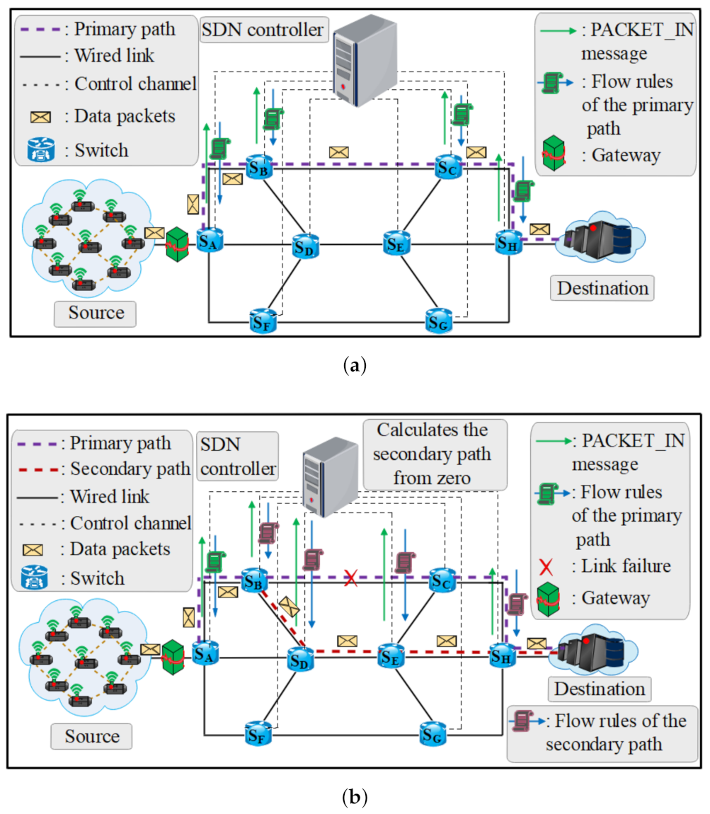
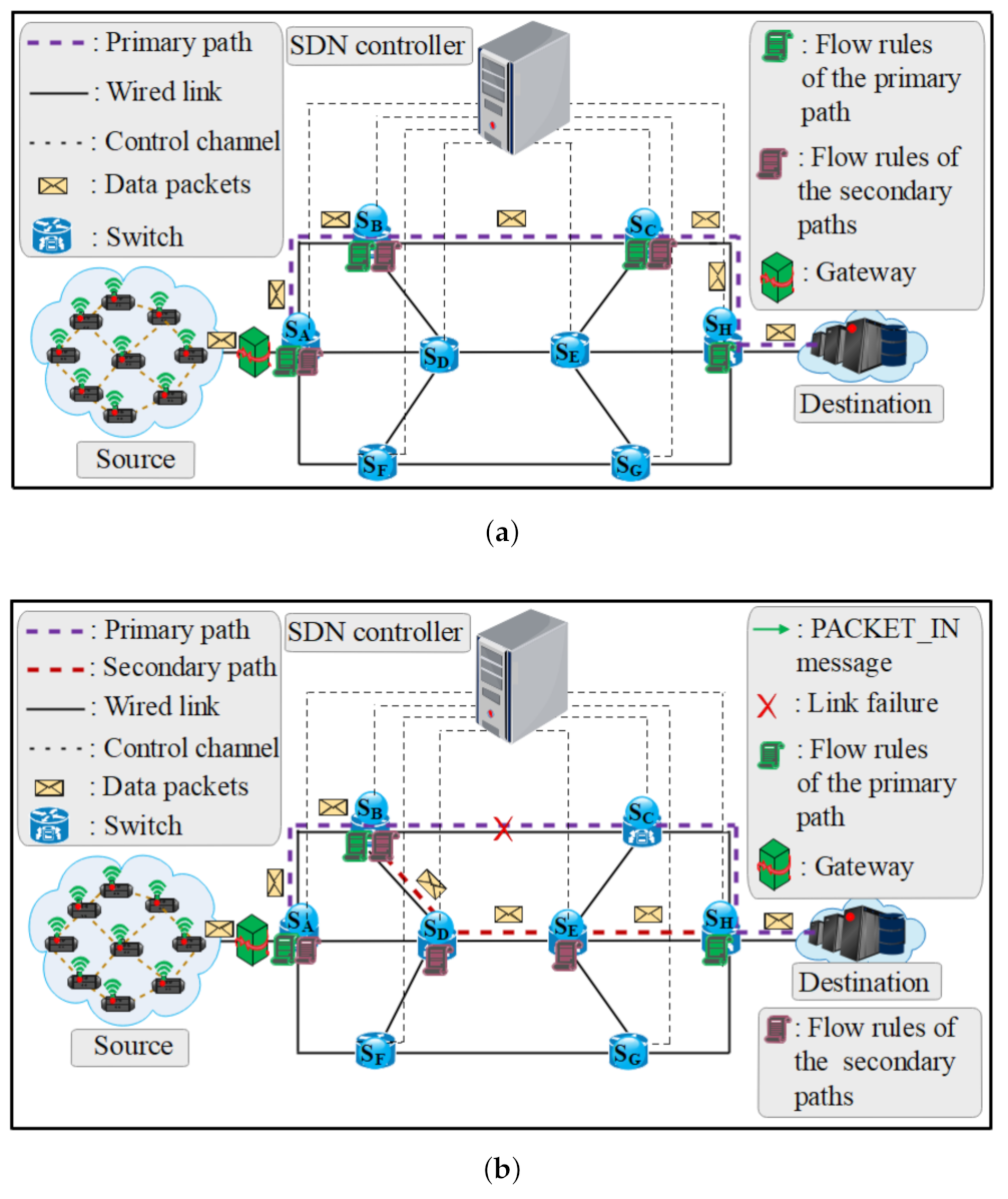
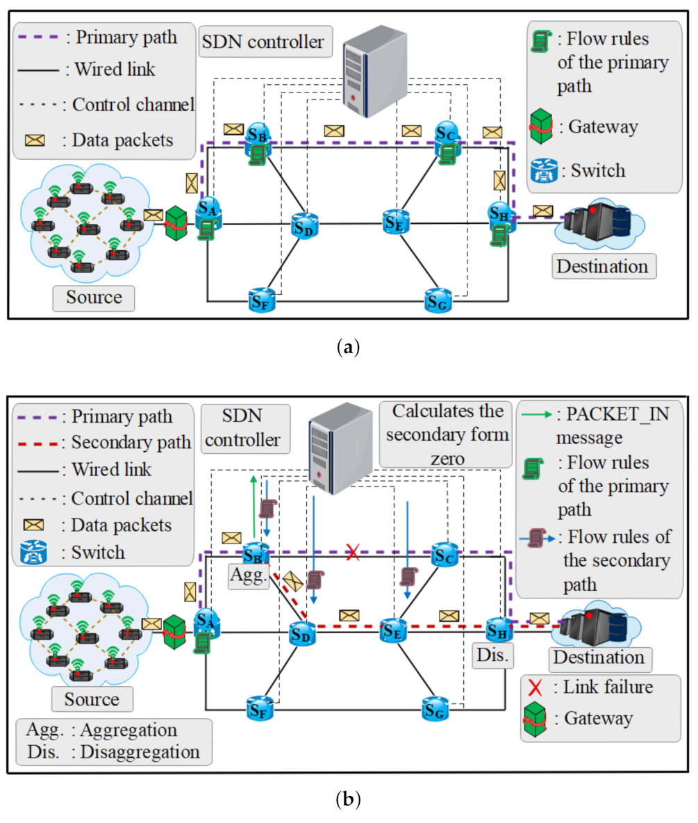
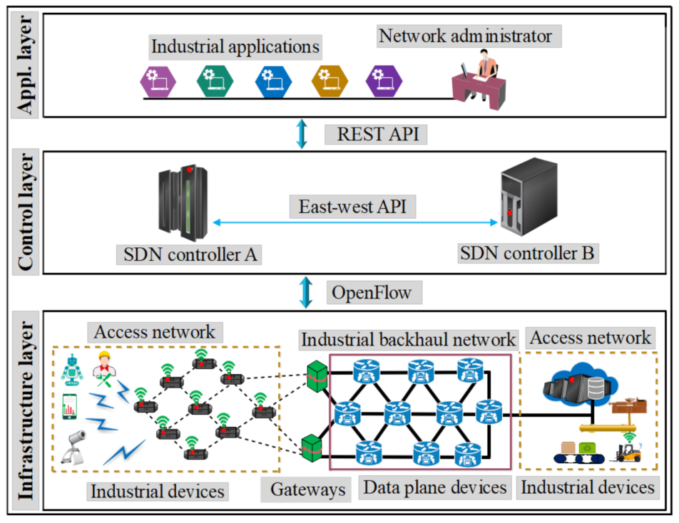
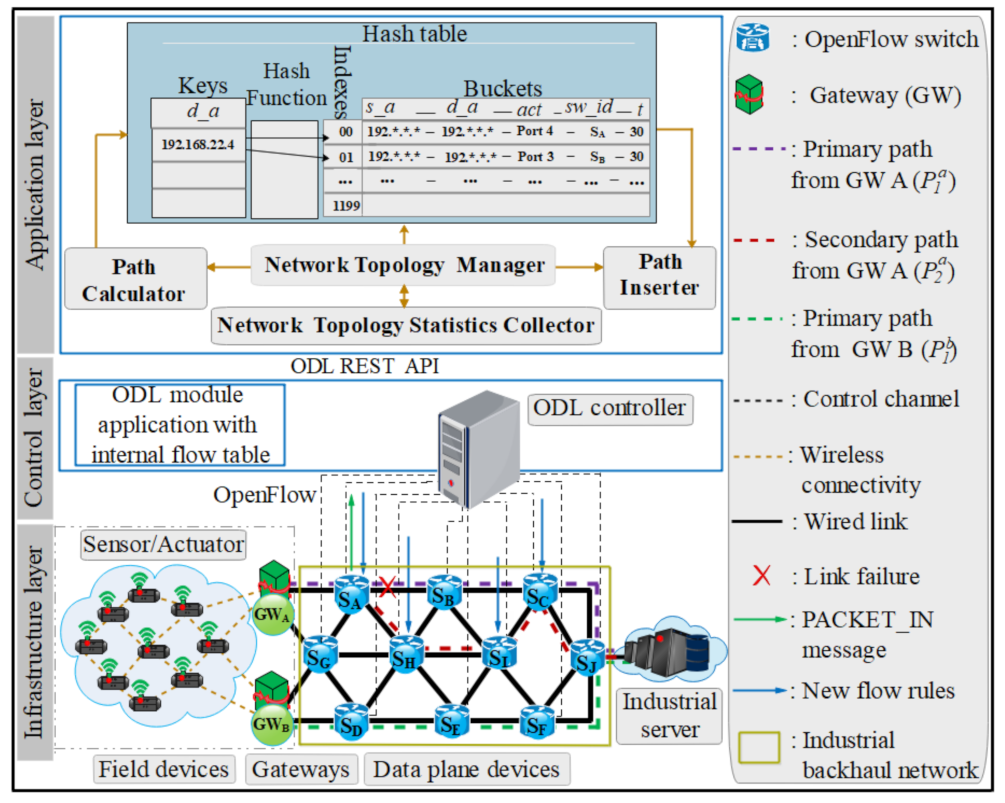
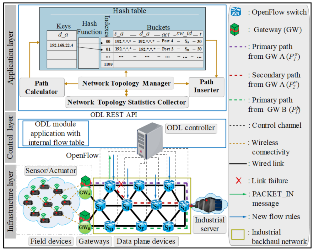
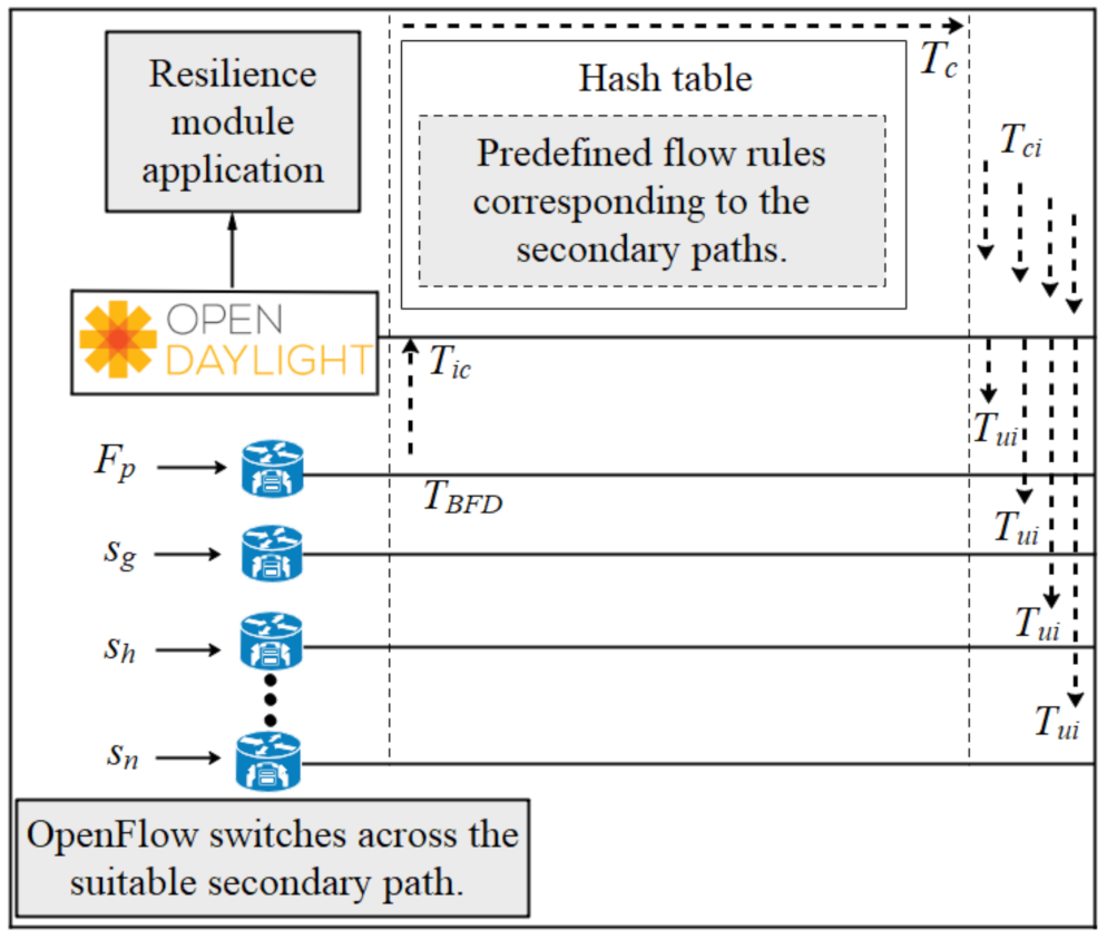
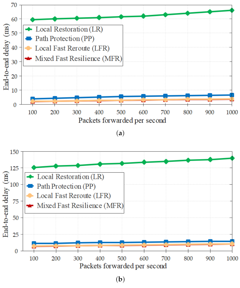
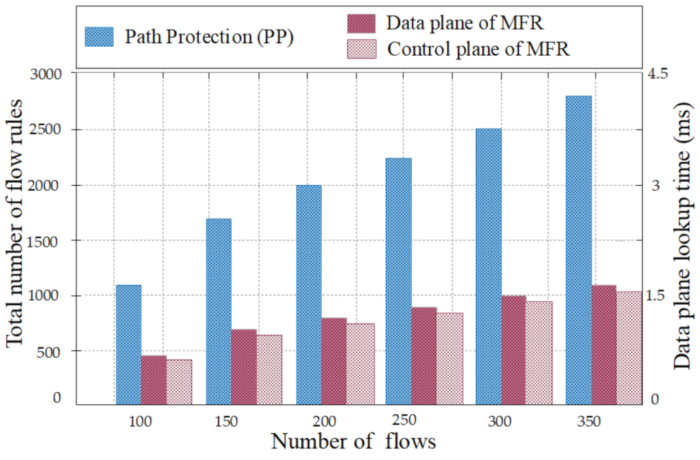
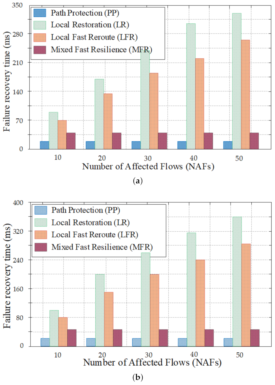
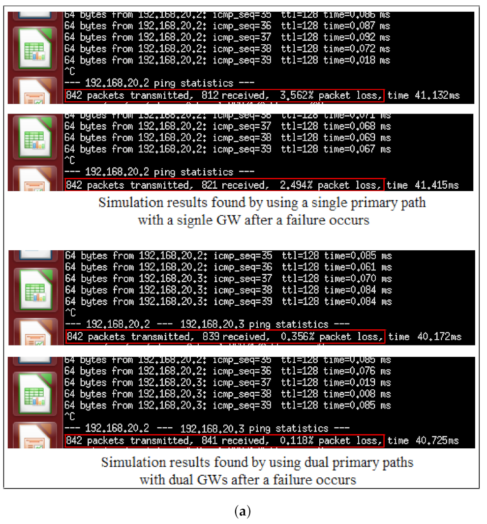
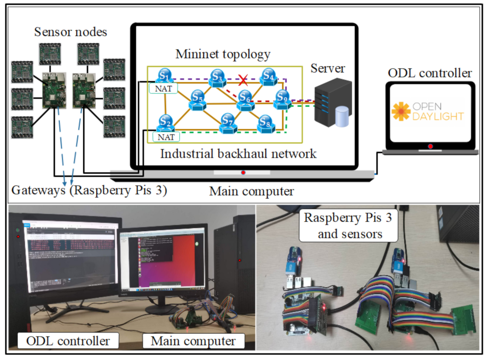
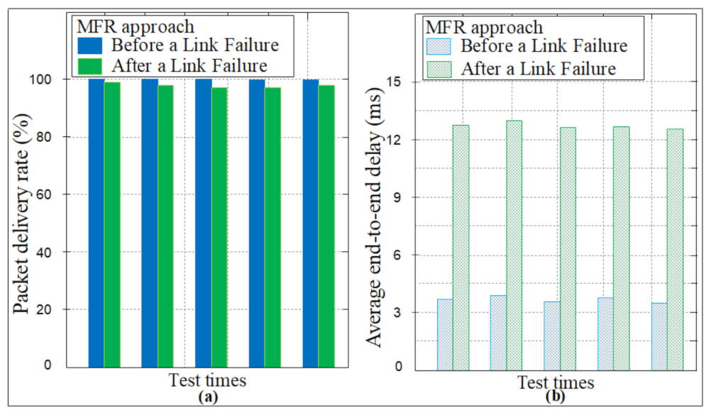
Table 1.
A comparison of related studies with regards to the sort of resilience (protection, restoration or both), key metric, and approval methodology.
Table 1.
A comparison of related studies with regards to the sort of resilience (protection, restoration or both), key metric, and approval methodology.
| Literature | Sort | Key Metrics | Approval |
|---|---|---|---|
| Al-Rubaye et al. [28] | Restoration | End-to-end latency and data traffic flow | Simulation |
| Zhang et al. [29] | Restoration | CPU utilization of SDN controller (NOX) and its average, end-to-end delay and its average | Simulation |
| Vestin et al. [30] | Protection | Delay, network load, message reception interval, and request-response time | Prototype |
| Jhaveri et al. [33] | Restoration | Estimated end-to-end delay, average throughput, path restoration delay, and success rate | Simulation |
| Muthumanikandan et al. [21] | Restoration | Recovery time, response time, throughput, and latency | Simulation |
| Satchou et al. [26] | Restoration and protection | Latency when there is a failure | Simulation |
| Li et al. [24] | Restoration and protection | Average recovery time, controller processing time, flow entries, PLR, and link congestion | Simulation |
| Adrichem et al. [32] | Protection | Recovery time | Prototype |
| Zhang et al. [27] | Restoration | Failure recover time and number of flow entries | Simulation |
| MFR | Mixed of protection and restoration based on the dynamic hash table | Failure recovery time, end-to-end delay, PLR, lookup time, and packet delivery rate | Simulation and testbed |
Table 2.
Summary of key notations.
| Notation | Description |
|---|---|
| G is an undirected graph, where V is | |
| the set of nodes (switches | |
| and gateways) and E is the set of links. | |
| the link from node i to node j. | |
| the scale factor for the delay (d). | |
| the scale factor for the loss (l). | |
| the source node of the path k. | |
| the destination node of the path k. | |
| the delay of the link . | |
| the packet-loss probability on the link . | |
| the weight of the link , computed as . | |
| The number of the flow corresponding to | |
| the path sent on the link . | |
| the maximum tolerable delay. | |
| the maximum tolerable loss. | |
| the bandwidth available on the link . | |
| the bandwidth required by the path k. | |
| the primary path from gateway (GW) A. | |
| the primary path from GW B. | |
| the secondary path from GW A. | |
| the secondary path from GW B. | |
| the switches across the . | |
| the flow rules corresponding to the . | |
| the switches across the appropriate . | |
| the flow rules corresponding to the . | |
| the switches across the . | |
| the switches across the appropriate . | |
| f | the failed link in the network topology. |
| the flow rules corresponding to the . | |
| the flow rules corresponding to the . | |
| the number of intermediate switches on the . | |
| the number of intermediate switches on the . | |
| the number of intermediate switches on the . | |
| the number of intermediate switches on the . | |
| working_path_A | the optimum path used for sending the |
| packets from GW A to the destination. | |
| working_path_B | the optimum path used for sending the |
| packets from GW B to the destination. | |
| HT | the hash table. |
Publisher’s Note: MDPI stays neutral with regard to jurisdictional claims in published maps and institutional affiliations. |
© 2021 by the authors. Licensee MDPI, Basel, Switzerland. This article is an open access article distributed under the terms and conditions of the Creative Commons Attribution (CC BY) license (https://creativecommons.org/licenses/by/4.0/).
Share and Cite
MDPI and ACS Style
Josbert, N.N.; Ping, W.; Wei, M.; Li, Y. Industrial Networks Driven by SDN Technology for Dynamic Fast Resilience. Information 2021, 12, 420. https://0-doi-org.brum.beds.ac.uk/10.3390/info12100420
AMA Style
Josbert NN, Ping W, Wei M, Li Y. Industrial Networks Driven by SDN Technology for Dynamic Fast Resilience. Information. 2021; 12(10):420. https://0-doi-org.brum.beds.ac.uk/10.3390/info12100420
Chicago/Turabian StyleJosbert, Nteziriza Nkerabahizi, Wang Ping, Min Wei, and Yong Li. 2021. "Industrial Networks Driven by SDN Technology for Dynamic Fast Resilience" Information 12, no. 10: 420. https://0-doi-org.brum.beds.ac.uk/10.3390/info12100420
Note that from the first issue of 2016, this journal uses article numbers instead of page numbers. See further details here.