Article

THREATGET: Towards Automated Attack Tree Analysis for Automotive Cybersecurity

by
Sebastian Chlup
*,
Korbinian Christl
,
Christoph Schmittner
,
Abdelkader Magdy Shaaban
,
Stefan Schauer
and
Martin Latzenhofer
Austrian Institute of Technology GmbH, Giefinggasse 4, 1210 Vienna, Austria
*
Author to whom correspondence should be addressed.
Submission received: 30 September 2022 / Revised: 20 December 2022 / Accepted: 21 December 2022 / Published: 27 December 2022
(This article belongs to the Special Issue Automotive System Security: Recent Advances and Challenges)

Abstract

:
The automotive domain is moving away from simple isolated vehicles to interconnected networks of heterogeneous systems forming a complex transportation infrastructure. The additional means of communication result in increased attack surfaces which can be exploited by physical as well as remote attackers if not secured thoroughly. Thus, the automotive sector is exposed to new cyber risk factors. Consequently, joint approaches targeting securing vehicles and infrastructure by identifying and mitigating potential threats for the automotive domain have been developed in several research projects. This paper builds on developments originating from these projects and correlated standards and regulations. Moreover, the extension of an existing threat modeling tool—THREATGET—with a novel automated approach toward attack propagation will be introduced. Therefore, we will conduct an analysis of a real-world example from the automotive domain. Furthermore, we will identify and analyze potential threats and discuss their accumulation to automatically generate an attack tree.

1. Introduction

The road vehicle domain is undergoing a transformation, from singular and isolated vehicles to an interconnected transportation network. This so-called CCAM (cooperative, connected, and automated mobility) or C-ITS (cooperative intelligent transport system) refers to a transportation system where the cooperation between two or more systems (personal device, vehicle, roadside, and central) enables and provides a transportation system that offers better quality and an enhanced service level. Cooperation and communication enable an enlarged awareness, increased efficiency, and novel safety features compared to isolated vehicle systems. Considering that standard vehicles already possess up to 150 electric control units (ECU), this will increase the overall complexity and introduce a new level of interdependency between vehicles and infrastructure.
While in the current implementations the cooperative aspect is mainly on the level of an additional information source for the driver to interpret and react to, there is a parallel transformation on the level of the vehicle, from a manually controlled system to an automated system. With the convergence of both transformations, vehicles will communicate and cooperate within themselves and with the larger transportation infrastructure to autonomously react to the received and exchanged information.
While this has the potential to increase the efficiency and safety of transportation, it also introduces more significant risks in regard to cybersecurity attacks. The increased exposure of vehicles due to increased connectivity opens up new vulnerabilities. Within three years, from 2018 to 2021, the number of cyberattacks on cars increased by 225% [1,2]. In the past, attacks were carried out physically or in the proximity of the vehicle. However, this trend is changing, as in 2021 85% of attacks originated from remote sources [1,2]. Attackers can send manipulated information to automated vehicles and cause malfunctions or remotely control an automated vehicle. These additional safety risks extend the already existing dangers for cybersecurity to cause and facilitate vehicle thefts, manipulate and steal personal data or restrict the operation and availability of the vehicle. As far as recent statistics for attack categories are concerned, almost 40% of attacks result in a data or privacy breach, while nearly 28% target car-theft or break-ins, and around 20% are aimed at manipulating control systems [2,3]. When it comes to electric mobility, the number of cybersecurity risks increases, especially when considering software-driven charging infrastructure which could potentially be hacked.
This increased risk and potential to cause not only disturbances on the level of singular vehicles but on the overall road transportation level led to the introduction of novel automotive security standards [4] and automotive security regulations [5]. Both are based on the concepts of risk and security management.

2. Materials and Methods

In order to avoid incidents as depicted in Section 1 as best as possible, OEMs (original equipment manufacturers), as well as infrastructure manufacturers and operators must ensure that their systems are secure against cyber attacks. It is a well-known fact that almost every hardware or software component has inherent security vulnerabilities. While some weaknesses are known and can be treated, others may go undetected and be exploited for more extended periods. However, it is not only about the components themselves, the configuration also plays an important role. Authentication, authorization, encryption, or DDoS (distributed denial of service) mitigation measures can already filter out multiple threats so that potentially vulnerable components cannot be reached. This is represented by the so-called defense-in-depth approach, where multiple layers of security and defense are staggered to ensure that if one layer fails, additional layers will restrict further steps.
Moreover, in order to decide on the placement of functions (e.g., where in the layered defense system a function or data are stored) it is necessary to evaluate potential risks and decide on suitable treatments. As such, cybersecurity management starts with the beginning of the system lifecycle and influences the complete system engineering. However, cybersecurity management is not an approach that is conducted only once. As mitigation measures evolve, so do potential threats. Cybersecurity should be considered throughout all system lifecycle phases, whether design, development, or maintenance. There is a need to be able to react to new kinds of threats. Throughout the years, multiple strategies to counter threats and reinforce technological systems against threats have been developed. The following sections elaborate on the history of methods developed.

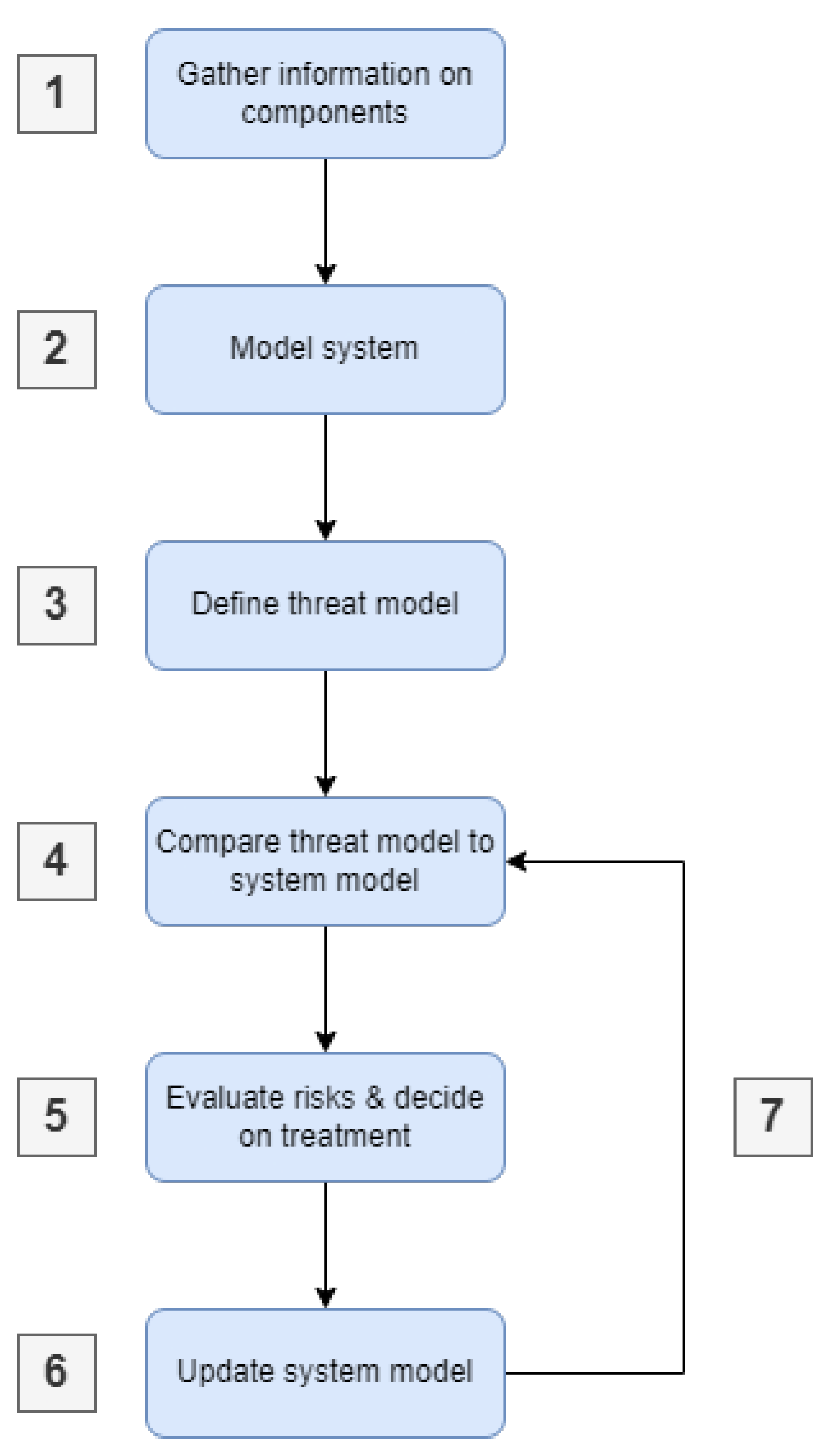
2.1. Generic Cybersecurity Management

Cybersecurity management relies on the knowledge of potential risks in order to manage them. A widespread approach for this is threat modeling. Threat modeling represents an iterative approach to identifying potential threats to a technological system. It consists mainly of two parts: Firstly, a system model that holds all information of the system under consideration (SuC) throughout its lifecycle phases (design, development, maintenance). In most iterations of threat modeling, it is represented by a data-flow diagram (DFD) depicting components, connections, and security properties. Secondly, a threat model that is based on known weaknesses and vulnerabilities. By comparing both, the system model and the threat model, potential threats within the system can be identified. Figure 1 shows a procedural illustration of the threat modeling process.
The iterative process of threat modeling is described by the following six steps (based on [6]):
1.
Gather information on components that should be used during the design/development phase, or for productive systems, information on existing components.
2.
Model the system with all communication channels and security assumptions as precisely as possible.
3.
Define a threat model with information from experts, and known threats and derive them from available sources (e.g., threat intelligence).
4.
Compare the threat model to the system model to identify potential threats and system weaknesses.
5.
Evaluate the risks of identified threats and decide on the risk treatment options based on impact and likelihood.
6.
Update the system model with mitigation strategies and security countermeasures.
7.
Go back to step 4 to identify newly introduced threats or threats that remained untreated.
Throughout the years, various threat modeling techniques have been developed (STRIDE, PASTA, LINDDUN, etc.) [7]. The threat modeling approach presented in this work is based on the STRIDE methodology developed by Microsoft. STRIDE extends the CIA (confidentiality, integrity, availability) model and allows it to relate threats with security attributes [8], thus allowing a view of threats from the perspective of an attacker. The STRIDE method is not only targeted at the automotive sector; it is a generic method that can be applied in any sector. STRIDE is an acronym for Spoofing, Tampering, Repudiation, Information disclosure, Denial of service and Elevation of privileges. It started as a brainstorming methodology to identify what can potentially go wrong in the system under consideration and was later extended to include a formal and automatically applicable description of weaknesses of elements and interactions [9,10]. STRIDE intends to ease the identification of potential threats. The purpose of STRIDE is to find and enumerate potential flaws within a system. Mitigation measures or attack patterns are not its focus. Furthermore, STRIDE helps to analyze vulnerabilities that could be exploited by an attacker; however, it has no standardized methodology of how it should be applied [11].
Simply identifying a potential threat is only one side of the medal. Another aspect that needs to be considered in threat modeling is the derivation of a risk rating for the identified threats. Consequently, a risk assessment model called DREAD has been developed by Microsoft. DREAD stands for Damage potential, Reproducibility, Exploitability, Affected users and Discoverability. Besides DREAD there are also other rating schemes in usage.
A list of common threat modeling methods as well as rating schemes is shown in Table 1.

2.2. Automotive Cybersecurity Management

As vehicles become increasingly complicated and interconnected [15,16] they can be classified as cyber–physical systems (CPS) [17,18].
This means that they are a potential target for remote attacks. This new security threat and the interconnected world require new approaches to cybersecurity. Therefore, all stages in the automotive lifecycle need to incorporate cybersecurity management [16,19].

2.2.1. Research Projects

Multiple European Union research projects such as EVITA, OVERSEE, and HEAVENS investigated multiple directions for securing the automotive sector. They focused on analysis, engineering, testing, and developing technology related to the security of vehicles and mobility services. They also paved the way for implementing state-of-the-art security solutions by introducing new concepts, integrating security components from different domains, and creating expertise-sharing platforms.
E-safety vehicle intrusion protected applications, also known as the EVITA project (https://www.evita-project.org/index.html (accessed on: 24 August 2022)), was initiated in 2008 to design, verify, and prototype security building blocks for onboard automotive networks. A novel method for conducting onboard automotive risk assessments was developed during the research. As discussed in [20], EVITA was responsible for defining the onboard vehicle security requirements. In accordance with these criteria, the organization built a secure architecture and protocols of communication for the automotive onboard network [16].
The Open VEhiculaR SEcurE platform (OVERSEE) project was launched in 2010 to provide internal and external vehicle interactions for automotive applications. OVERSEE created a software and communication infrastructure that is open and standardized. The idea is to be able to execute external apps without negatively affecting one another or any of the internal vehicle parts and components. The security frameworks that were observed in the OVERSEE platform had the goal of managing inferences that could have been caused by applications, human mistakes, or malicious activities [16,21]. The fact that external applications often consume the same resources as internal applications is one of the most important challenges. As a result, it is of the utmost importance to ensure that applications downloaded from the internet do not compromise the assets of the car or have a negative impact on the safety of the vehicle [16].
The HEAling Vulnerabilities to ENhance Software Security and Safety (HEAVENS) project was initiated in 2013 with the objective of building new techniques for assessing security and locating security vulnerabilities in the automotive sector. The fundamental objective of the project is to create a collection of security procedures that the system developer must follow in order to provide a protective measure for the car’s critical assets. This reduces the risk that is associated with these security gaps, which are susceptible to being exploited by attacks. HEAVENS presented primary concepts about trustworthiness and security, including security characteristics and goals [22]. As an extension of the CIA triad (i.e., confidentiality, integrity, availability), the project utilized eight security attributes, including confidentiality, integrity, availability, authenticity, authorization, non-repudiation, privacy, and freshness. In addition, the HEAVENS system incorporated several security goals to counteract the detected risks to conform to the security procedures, and assumptions [8,16] and developed a security analysis methodology.

2.2.2. ISO/SAE 21434

Based on the publication of SAE J3061 “Cybersecurity Guidebook for Cyber-Physical Vehicle Systems” [23] and multiple identified potential weaknesses and vulnerabilities in existing automotive systems, the automotive domain decided to develop best-practice guidance in the form of an international standard for the topic of automotive cybersecurity engineering. ISO/SAE 21434 [24] took the experience from the research and industrial approaches towards cybersecurity and developed a risk-management-based approach to automotive cybersecurity.
The standard focuses on the engineering of automotive systems, from concept to development, implementation, production, and operation. In addition, a set of supporting or continuous processes on organizational and project levels are defined that support the achievement of cybersecurity. During development, UN WP29 started the development of automotive cybersecurity regulation, and here the topic of compliance was also treated.
Risk management according to ISO/SAE 21434 is based on a set of approaches that can be combined to define a suitable TARA process. Summarized, the TARA starts during the definition of the item, e.g., the definition of the function on the vehicle level for which a system or combination of systems is developed and results in the definition of risk treatment decisions for the item. Steps include [24]:
  • asset identification: identifies assets, including their relevant cybersecurity property (CIA), which leads to one or more damage scenarios if the cybersecurity property is violated.
  • threat scenario identification: describe a potential threat that could cause the violation of a cybersecurity property of an asset.
  • impact rating: rates the impact on different categories (safety, financial, operational, privacy) of a damage scenario. In the automotive domain, safety is normally rated in four levels adapted from ASIL. A detailed definition of the terms can be found in the ISO/SAE 21434.
  • attack path analysis: identifies a potential attack path or if multiple attack paths are possible an attack tree that could enable an attacker to execute an identified threat scenario.
  • attack feasibility rating: rates the feasibility, e.g., the likelihood of an attack path based on a rating scheme and subfactors.
  • risk value determination: uses a risk matrix to combine impact rating and attack feasibility rating to derive the risk for each combination of impact and attack feasibility.
  • risk treatment decision: decides on the suggested course of action, e.g., if a risk is accepted or additional measures are needed.
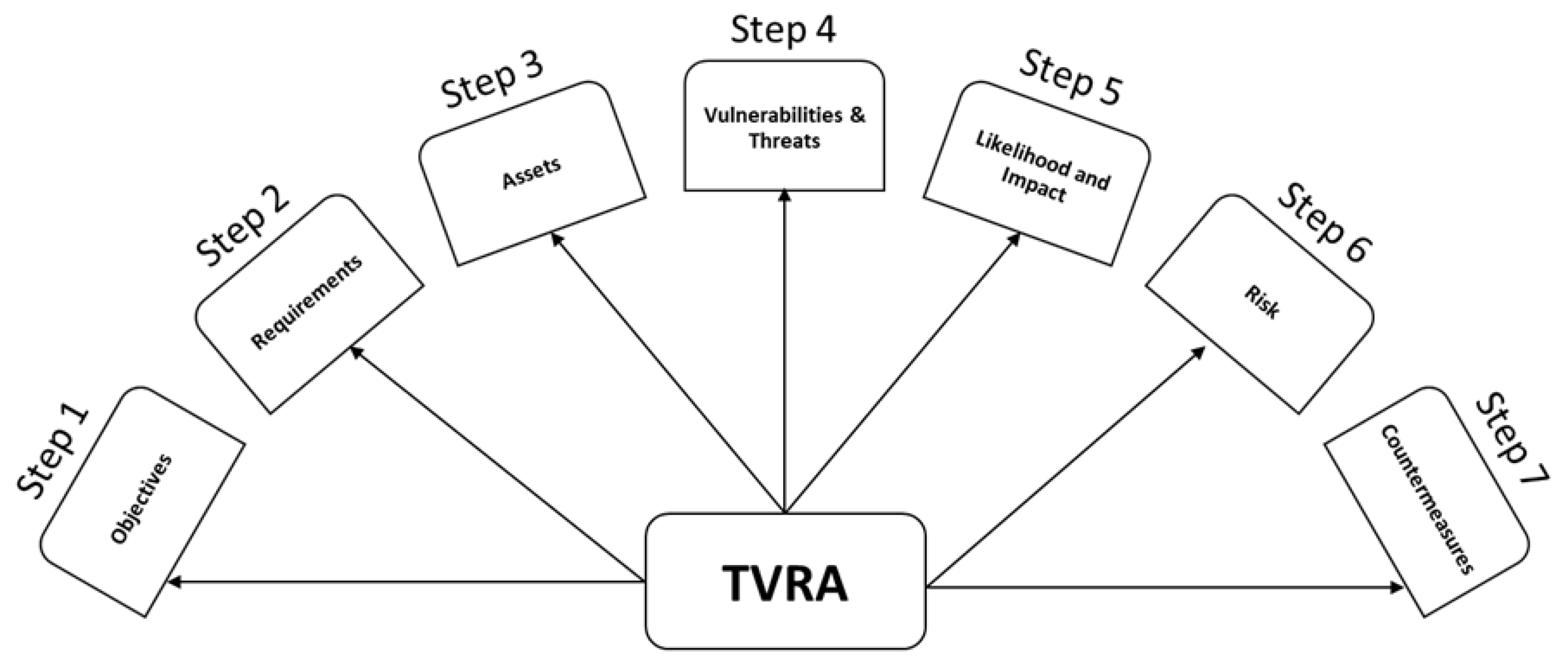
While there are some dependencies between the steps, the order of activities is not defined.

2.2.3. ETSI TVRA

The European Telecommunications Standards Institute (ETSI) worked on the development of automotive-related standards as part of their task to develop standards for C-ITS. In one of these activities, the ETSI TVRA (ETSI threat, vulnerability, and risk assessment) system was introduced as a systematic method for prioritizing and assessing risks to a system [25]. Figure 2 illustrates the steps of the TVRA method.
The diagram represents seven steps of the TVRA method as follows [25]:
1.
Establish the objectives that need to be met in terms of security goals.
2.
Establish what level of security requirements are required.
3.
Create a checklist of all the system’s assets.
4.
Identify the system vulnerabilities and potential cyber threats.
5.
Determine how likely an attack is and the extent of its impact.
6.
Determine the risk’s scope by combining the likelihood and impact calculation results.
7.
Provide detailed guidance on the proper precautions against existing security issues.

2.2.4. UNECE WP29

The UNECE (United Nations Economic Commission for Europe) regulation (UN R155) [26] on the cybersecurity-related requirements for the type approval of vehicles describes a set of requirements concerning the cybersecurity management at the complete lifecycle and risk management for a vehicle type [26]. In order to approve a vehicle type, compliance with the cybersecurity management system (CSMS) and the risk-based approach to the vehicle type have to be demonstrated. For risk-based engineering, an example list of current threats is given. Risks must be identified and evaluated and if they are considered as not acceptable, a risk treatment has to be designed, implemented, and tested. For vehicle type approval, these decisions have to be demonstrated, e.g., the complete traceability from analysis to tested risk treatment. UN R155 is in force since July 2022 for all new vehicle types and will be required from July 2024 for all new vehicles.

3. THREATGET—Cybersecurity by Design

Current vehicles with up to 150 ECUs, a high number of interfaces, and external connections, and multiple vehicle networks challenge the manual conduction of risk analysis, work product generation, and traceability. While existing risk management and risk analysis tools are only partially usable, in recent years and with the increased focus on automotive cybersecurity, domain-specific tools have started to get more usage. We present here THREATGET as a tool built for the automotive domain.

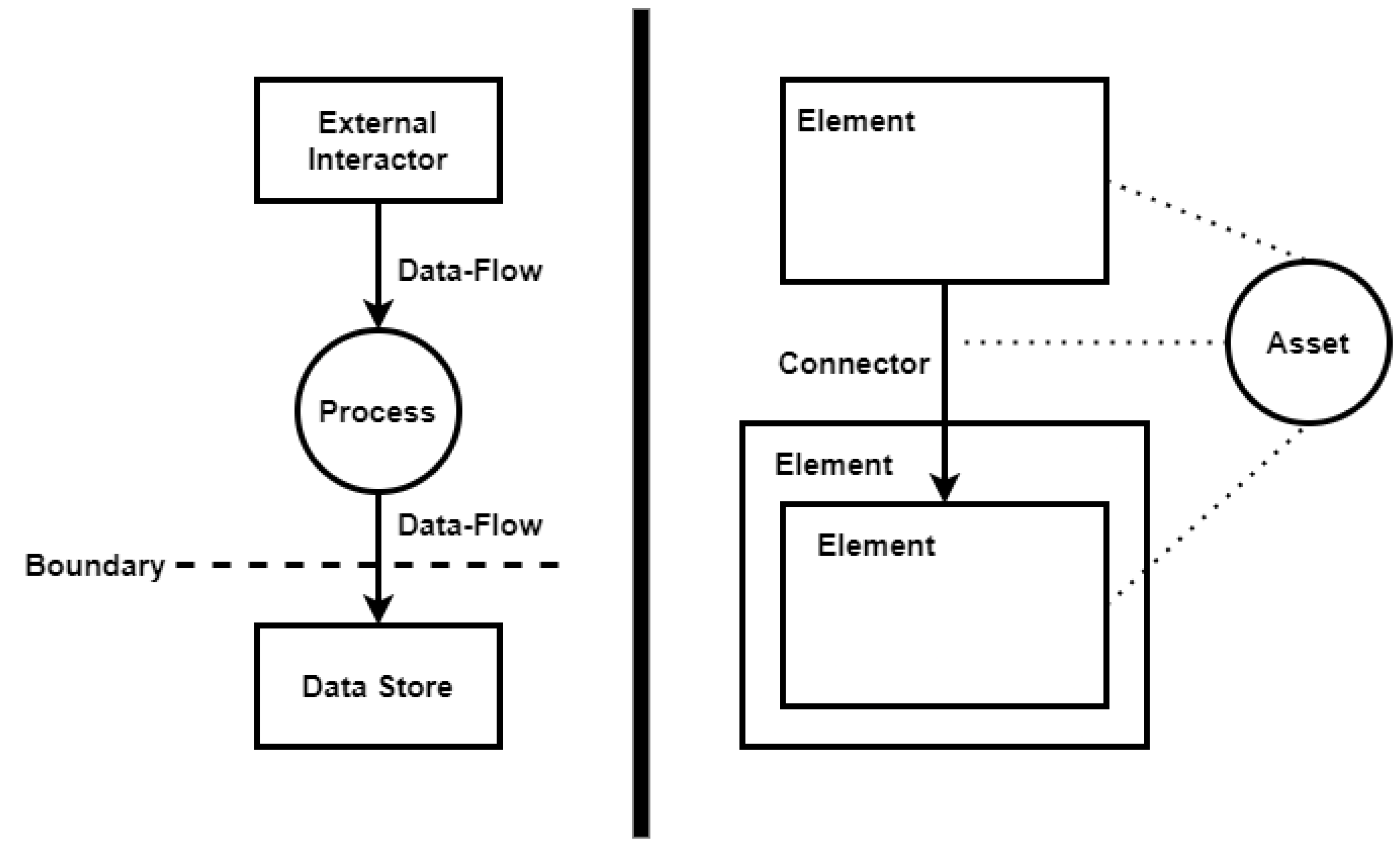
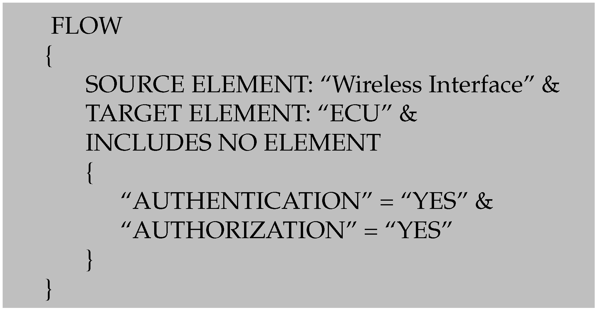
3.1. THREATGET’s Approach towards Threat Modeling

THREATGET is a threat modeling tool that incorporates developments from previous research projects, standards, and regulations. As described in Section 2.1, threat modeling is based on two main components: the system model and the threat model. In THREATGET, the system model is a digital twin of the system under consideration. This digital twin is represented by a model of software and hardware components, assets, security attributes, and communication channels. It can be created at the start of the concept phase. The threat model represents the knowledge about known vulnerabilities and threats [9]. These two components form the basis of THREATGET. In contrast to the Microsoft Threat Modeling Tool, which relies on a data-flow diagram without hierarchies [9], we decided to adapt the basic modeling to better fit the automotive domain, developing an extended data-flow diagram (EDFD) to model an automotive system. We classify individual system components as “elements”, “connectors”, and “assets”. Elements describe both physical and logical components, such as an ECU, server, or software running on a device. Connectors depict data flows between components. Assets are used to show where valuable data, information, or functions are located. Moreover, the EDFD allows hierarchical modeling and, therefore, a deeper analysis of a real-world system. Figure 3 displays the differences between a regular DFD and our EDFD.
For further distinguishing between components, they can be assigned a type (e.g., ECU, server, sensor, actuator). Furthermore, all these types can be assigned safety and security properties. This type-based concept facilitates reusable component types.
One of the core features of THREATGET is the automatic threat identification and analysis of the modeled system. To extract all relevant semantic information from the system model and evaluate it in the context of a threat analysis, we have created a domain-specific language (DSL). This DSL allows us to define threat and vulnerability information in a format that is readable by both humans, and machines and enables the formulation of threats in a uniform format. The result is, what we call, an “anti-pattern”—a pattern that describes a configuration that cyber-resilient systems should not include (i.e., a vulnerability). In case an anti-pattern matches the system model, a potential threat is detected and added to a resulting threat catalog. The example in Figure 4 describes such a threat in the form of an anti-pattern.
An element with the assigned type “Server” that has neither an “Authentication” nor “Authorization” mechanism would make the described server component vulnerable, as an attacker may gain access to this server if it is accessible. For demonstration purposes, a simple example of a threat rule was chosen above. AIT’s knowledge database contains a large number of more sophisticated anti-patterns which form the threat model based on configurations of elements connections.
THREATGET’s automatic analysis exceeds the potential of approaches by previously existing analysis tools such as the Microsoft Threat Modeling Tool [27,28,29] and the OWASP Threat Dragon [30,31]. In these tools, the analysis results can vary greatly if the overall same system is modeled only slightly differently. Consider including a gateway between two connected components. Although there is another component in between, most of the detected threats should remain the same as the gateway is simply propagating the communication flow further in case no mitigation measures are defined. However, this is not possible in other tools, as they depend on a rather static approach, where an analysis result is only generated if the described patterns are exactly represented in the diagram. As a consequence, certain threats will not be triggered, as the patterns do not exactly match the system model. This means that threats will not be detected in case the components are not directly connected. For this reason, THREATGET offers a “flow-based” analysis that allows wildcards when defining an anti-pattern. This means that if a connection between elements of the system is to be examined, they allow for multiple different approaches to modeling, and elements do not necessarily have to be directly connected to fit the pattern [32]. In case a gateway is introduced between two connected components THREATGET will still consider these components as connected. An example is illustrated in Figure 5.
Figure 5 displays an excerpt of elements involved in V2X communication. The telematics module is used as means to communicate via wireless (Bluetooth and cellular) interfaces with an update server, a telematics server as well as the phone of the car owner. The Telematics module then communicates with the brake control ECU via a gateway and wired interfaces located within the car.
Current methods only evaluate an element by itself as shown in the anti-pattern from before. Another approach is the evaluation of the connection between two elements. These approaches are called STRIDE per element and STRIDE per interaction. However, this does not include potential attack paths throughout a system. It depends only on the configuration of single elements or the connection of two specific elements. This is also possible in THREATGET. However, our approach is more dynamic and thus more powerful when it comes to the analysis of a system model. Consider the following anti-pattern displayed in Figure 6 describing a potential attack on remote wireless interfaces.
The anti-pattern describes a flow from a wireless interface to an ECU. When taking a closer look at the model represented in Figure 5, we can see that the threat defined by the anti-patterns will trigger multiple times as the telematics module provides three wireless interfaces. One of these results is shown in Figure 7.
To this point, we cover the functionality on the same level as the Microsoft Threat Modeling Tool and the OWASP Threat Dragon. However, a flow is more than simply checking for the direct interaction between two elements. As mentioned before, it allows wildcarding elements. Therefore, it does not matter which elements are in between two components for an anti-pattern to trigger as long as there is a connection. However, it is possible to define additional constraints such as “INCLUDES NO ELEMENT” which check whether any element path has certain security properties such as authentication and authorization in the example. Additionally, other constraints are feasible such as “INCLUDES ONLY” which would be the opposite of the previous example, or “CROSSES BOUNDARY” which enables the detection of a flow crossing a trust boundary. Figure 8 displays one of the attack paths resulting from the flow anti-pattern.
As can be seen, the flow not only detects the interaction between the cellular interface and the telematics module, it detects complete attack paths that a remote attacker might take, in this case, to compromise the brake control.
As far as the analysis process is concerned, the system model is passed to THREATGET’s threat analysis engine, where the diagram is transferred into a data model. Then the predefined anti-patterns located in the database are compared with the system model. For a better understanding of the detected threat, the relation between the involved components is visualized.
A definition of the language, its semantic evaluation, and a description of the relationship between the system model and the threat model can be found in [33].
THREATGET is able to provide a more in-depth analysis of the system model than other existing tools by using the extended data flow diagram and the integration of attack paths. However, these are only the first steps toward automatically generating attack trees. The following section will explain the concept of attack graphs and emphasize the algorithm behind automatically building an attack graph and deriving attack trees.

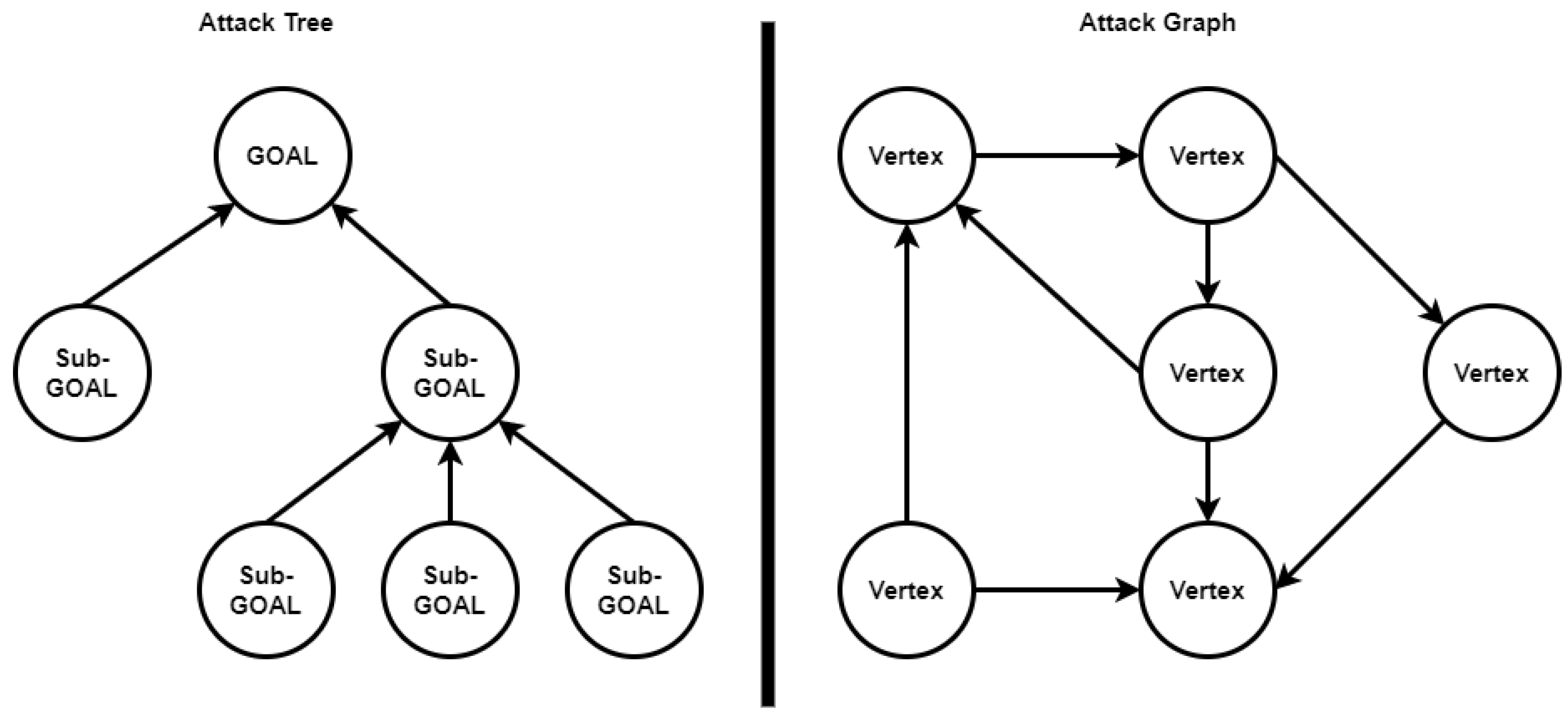
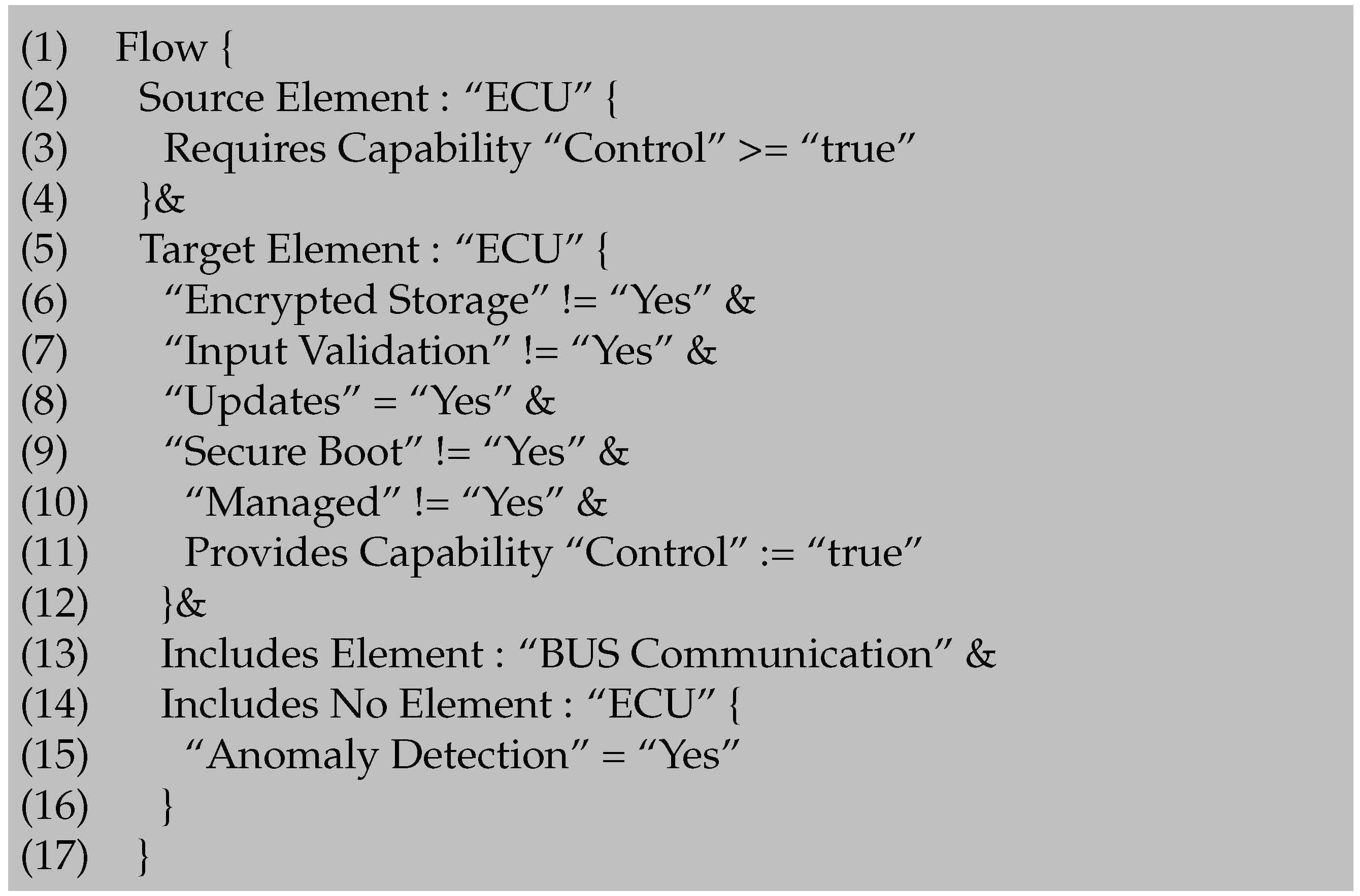
3.2. Automated Attack Tree Analysis

So far, developments and extensions to the existing threat modeling method have been discussed. This section will show how we have extended our previous approach to not only examine individual threats but also to include relationships and interdependencies between threats in the analysis result. The motivation behind this extension is to better understand, predict, and prevent complex attacks including multiple steps. With the increasing complexity and size of systems, the security measures that protect the system also need to improve. One example is here the defense-in-depth strategy, which increases the number of hurdles an attacker must overcome to successfully infiltrate a system. However, this increasing complexity and additional communication channels also increase the attack surface of our systems.
Through our work in several IT domains and in various research projects, we have come to realize that an attack usually consists of several complex interrelated steps and not just a single vulnerability that can be exploited. In most cases, the target component cannot be directly accessed [34,35]. Therefore, existing approaches that have already been used for similar problems were investigated. We found that the approach of fault trees and fault graphs had already been used in the field of vehicle safety to determine the effect of an individual failing system and how this might affect the remaining components of the vehicle [36] and was even adapted in security as attack trees. Moreover, the concept of prerequisites and postconditions is very well suited to describe the dependencies between threats in a system. On the one hand, a prerequisite describes one or more conditions that must be fulfilled for an event to occur. On the other hand, a postcondition describes one or possibly several states that are gained after the occurrence of an event [37].
Figure 9 shows a simplified attack tree with three different paths how to infiltrate an ECU. The example within the tree is intended to illustrate that security-related aspects can also be mapped with this concept. Each of the paths stands for itself and leads to the desired target and is, therefore, connected with a logical OR. The orange path shows how, in the concept of attack trees, several actions have to be connected with each other in order to reach a goal and thus represent a logical AND. The purple path shows how several individual steps are necessary one after the other to achieve a goal. Attack trees support properties in addition to individual steps, such as the likelihood or attack feasibility. In the given example, it is easier to infiltrate the ECU through the green path, i.e., via direct physical access, but it is less likely because physical access is often not available [38].
Attack trees describe attack steps an attacker might undertake to achieve an attack goal. They summarize multiple attack paths. This means that one must first identify the goal and then figure out what steps would lead to this goal. Current approaches rely on the manual generation of attack trees, which has two major drawbacks:
1.
Manual generation, like all manual threat analyses, depends on expertise and experience. Analysis conducted by an expert in hardware security will look different from an analysis done by an expert in cryptography. Consequently, completeness is difficult to argue, and paths might be overlooked.
2.
If an attacker can choose between different goals, or if multiple potential attackers need to be considered, generation, maintenance, and evaluation of the resulting trees are time-consuming. They need to be updated, depending on new vulnerability information or changes in the system architecture and larger system models result in an increased number of attack trees, which makes them grow in size.
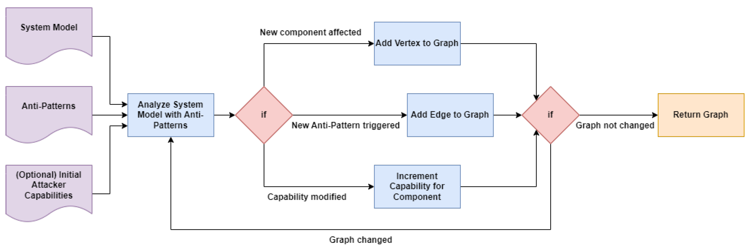
To address these challenges, we rely on automated generation, based on a threat database resulting from inputs covering multiple security sub-disciplines and the concept of attack graphs. With this, we combine threat modeling and attack tree analysis and automate the combined process. Figure 10 illustrates the difference between a tree and a directed attack graph.
A directed graph is very similar to the structure of a modeled system. The only difference is that, while the individual vertices of the graph represent the system components, the edges represent the respective connectors as well as implicit relations provided by the hierarchical structure within the system. Consequently, we concluded that it is possible to convert a system model represented by an EDFD into a directed attack graph without losing any semantic information. To define the prerequisites and postconditions of a threat, THREATGET was extended by the concept of capabilities. A capability describes a state that a component has or can take after a threat has occurred.
The following anti-pattern example refers to the attack tree in Figure 9. An ECU is checked for the “Authentication” and “Authorization” mechanisms. If it does not have either of these security measures, the attacker gains the capability of “Infiltrated” on the server.
Information 14 00014 i001
The above example describes the infiltration of an ECU. In this case, the attacker requires no means of authentication or authorization which allows them to infiltrate the ECU. Therefore, a variety of consequent attack steps become possible. An example going one step further is shown below.
Information 14 00014 i002
The above anti-pattern illustrates an attack step if an attacker has previously infiltrated the ECU. In case there are no measures such as anomaly detection, DoS mitigation, or malware protection in place, they can gain the capability “Control” over this ECU.
We have already described how we can use the concept of anti-patterns to automatically analyze a system model to detect potential threats. What makes THREATGET’s analysis unique is that it extends this concept by using capabilities to define threat dependencies. A defined capability in an anti-pattern can be both a precondition and a postcondition to a threat. Required or gained capabilities are dynamically queried, added, or modified during the analysis process. This means that for every component in the system model, applicable preconditions and security properties are checked. In case the anti-pattern is fulfilled a new postcondition may be achieved, thus forming a new precondition for a subsequent iteration of the analysis. Moreover, an existing capability can be updated to a higher level on the respective or following components, leading to consequent attack steps. Based on these results, an attack graph is progressively built step by step until the final state (when no more changes are made to the graph) is reached. In the following, we will explain the algorithm used to create the attack graph. Figure 11 shows the graph generation in a simplified form.
A total of three inputs are required for the analysis:
1.
The system model to be analyzed;
2.
The set of anti-patterns to be used for the analysis;
3.
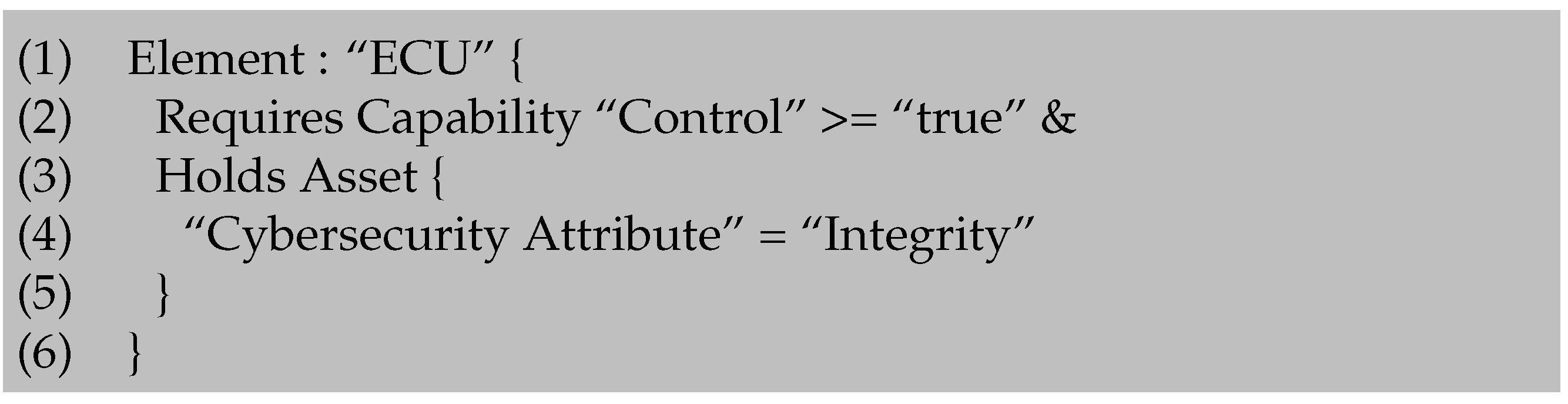
(Optional) A set of initial capabilities defined by the user before the analysis to model assumptions of attacker capabilities.
Initially, the attack graph is empty. If the user has defined a set of initial capabilities, these are transferred to the graph. Whereby, each capability is one initial vertex inside the graph. Subsequently, the algorithm enters the analysis phase. In this phase, the algorithm applies each rule from the given set to the system model. The results are stored temporarily. A result contains the affected system components and the resulting postconditions. After the analysis is completed, the results are compared with the attack graph. If the attack graph has changed after one iteration of the analysis, the analysis is repeated. If not, the graph is returned as the result. A change in the graph is triggered in the following cases:
1.
A new component has been affected and is, therefore, inserted into the graph as a vertex;
2.
A capability has changed because a rule has increased the assigned value;
3.
A new rule is valid, which leads to a new edge inside the graph.
We are aware that the repeated application of all rules leads to an increased workload. However, this is the only way we can ensure that the analysis is complete, as capabilities expand during iterations and the number of affected components can increase steadily. To prevent the algorithm from running into an infinite loop, we have specified that the assigned capability value can never decrease but only increase. Thus, we have an additional termination strategy that the algorithm must terminate at the latest when the attack graph contains all components as vertex and each vertex contains the highest value of each defined capability.
However, the attack graph also has a downside compared to the attack tree. When the system under investigation reaches a certain size and the number of threat data in the threat model increases, the view of the graph becomes complex.
For this reason, we decided to utilize attack graphs as an internal representation and use their provided data to generate attack trees. Each tree ends in a target representing the asset or element that is affected by the threat. This gives a structured view of the individual steps that the attacker could take at each level of the attack path. The attack trees are then derived from the attack graph at runtime. The extraction of the attack trees from the attack graph is done by a recursive query. The user selects a vertex within the attack graph for which the attack tree should be generated. The algorithm then extracts this vertex from the graph and defines it as the root of the tree. Then the algorithm follows all incoming edges to their source vertices and adds them to the attack tree. The algorithm is repeated until all paths in the graph reach an initial vertex. Now that the origin and the relevant aspects of the existing and novel methods have been discussed we present an example of their application within THREATGET.

4. Evaluation Example

4.1. THREATGET and TARA

THREATGET follows an approach similar to the TARA process proposed by the ISO/SAE 21434 standard. Therefore, it supports the definition of potential assets and the identification of damage scenarios. Furthermore, assets contain relevant cybersecurity property, impact type, and impact rating. By bringing threats and assets into relation the impact can be automatically assessed. This becomes possible through the integration of valuable assets into the system architecture and linking them with components and connectors in order to depict the asset’s location(s). Moreover, its threat model works based on a representation of known vulnerabilities and threats. Based on an underlying set of anti-patterns, potential threats and attack scenarios posed to the SuC can be detected. Alongside impact assessment, THREATGET offers automated suggestions for attack feasibility. Risk can then be calculated by applying a risk matrix scheme based on attack feasibility and impact ratings which is fully compatible with the one proposed in ISO/SAE 21434. As far as countermeasures are concerned, the iterative nature of threat modeling serves as means to reduce risks. Consequently, detected threats serve as input for a revised system model. However, as THREATGET may already be applied during the system design phase or integrated later on into the development process, the order of steps as depicted in the ISO/SAE 21434 may vary slightly. The attentive reader might have noticed some similarities with the TVRA shown in Figure 2. The two methods are related, and THREATGET can also follow the TVRA; however, the TARA process by ISO/SAE 21434 is our preferred way of analyzing threats and assessing risk. In the following sections, the results of a TARA process executed with THREATGET based on an automotive use case will be discussed.

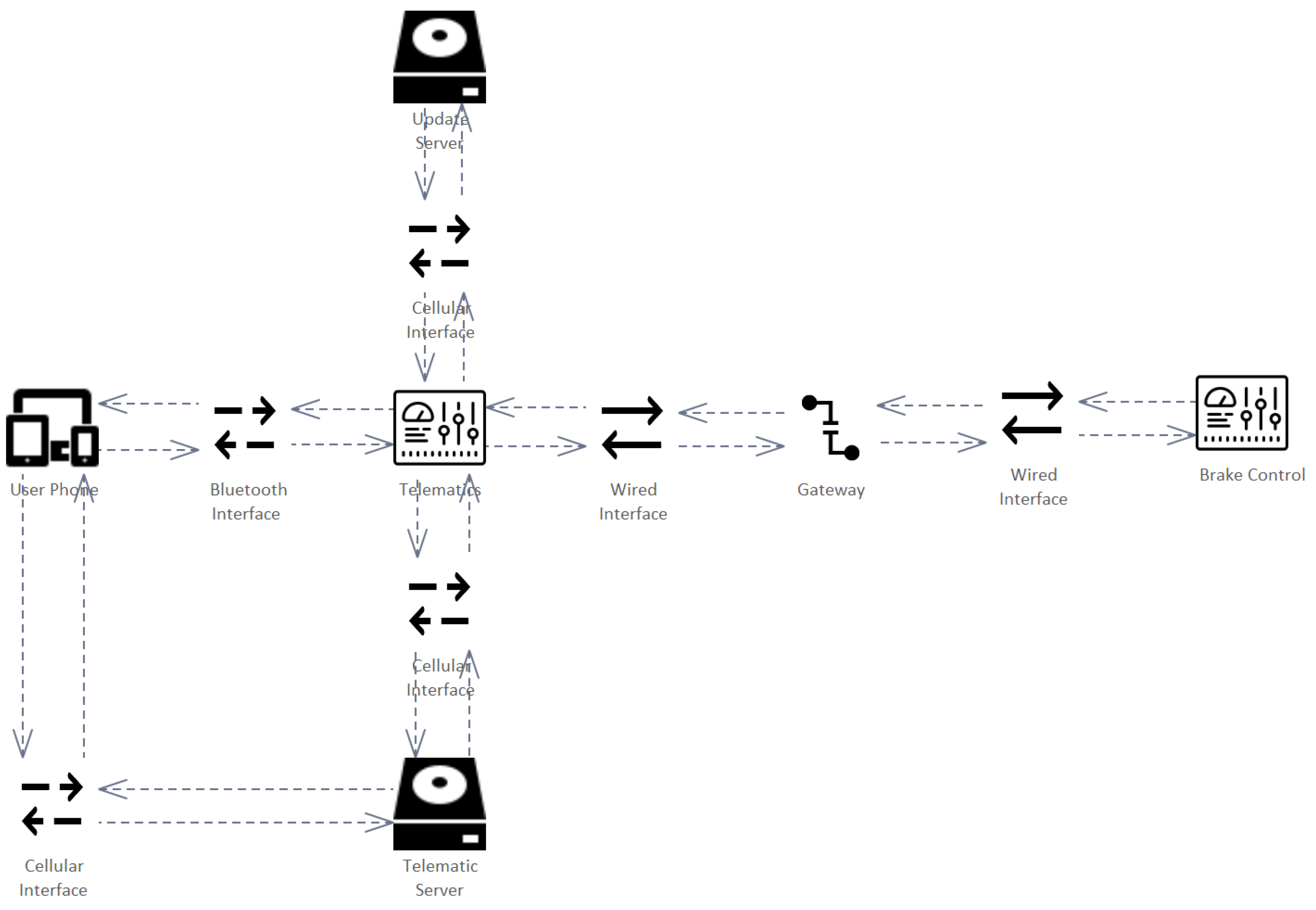
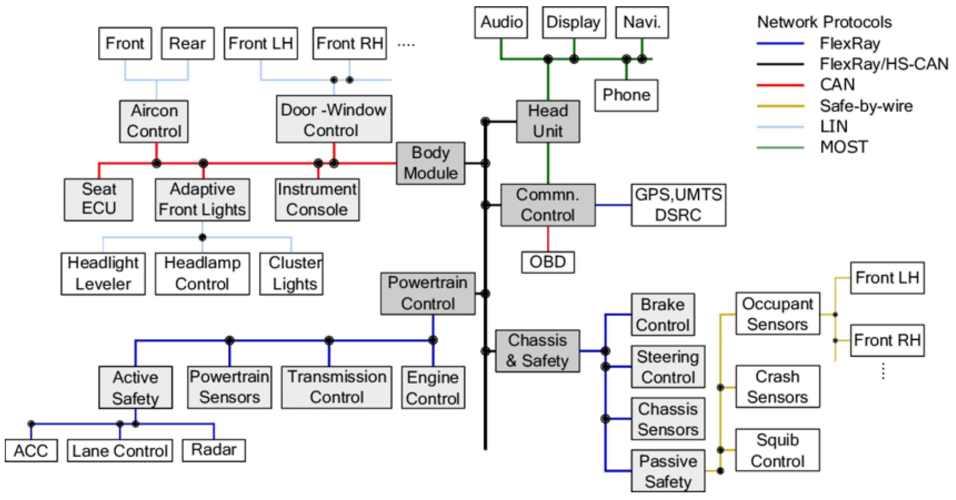
4.1.1. A Typical Automotive Architecture

Before getting into details about the execution of the TARA process, we would like to explain a typical automotive architecture. As mentioned before, a modern vehicle contains up to 150 electronic controls units, various wired and wireless communication interfaces, actuators, and busses. These components are used for communication with the infrastructure, the OEM (e.g., in terms of software updates), the key fob, internal communication and control of the car, and with devices (e.g., phones) carried by the driver. Figure 12 provides an excerpt of a reference architecture for a vehicle network.
Figure 12 describes a complex system of interconnected components controlling the vehicle. The head unit manages the information presented to the user (e.g., navigation) and takes care of the entertainment (e.g., connection to phone and audio). It is also known as the infotainment system. The communication control takes care of the communication interfaces with the outside, such as cellular interfaces, GPS, and wired interfaces for onboard diagnostics. In the meantime, the body module controls the windows as well as the air conditioning in the different sections of the car. Moreover, it controls the headlamp. The powertrain control is relevant for lane keeping and controls the engine based on a set of sensors. Finally, the lower right part of the diagram displays controls related to the chassis, steering, and braking. The diagram shows an architecture connected by multiple bus systems through which data is transferred to other components. As this example represents the general architecture of a real vehicle precisely we based our analysis example on this reference network.

4.1.2. Definition of Assets and Damage Scenarios

In terms of impact rating, THREATGET currently supports four possible values which are derived from ISO/SAE 21434. These are “Negligible”, “Moderate”, Major”, and “Severe”. For demonstration purposes, we defined two types of assets with regard to different aspects.
1.
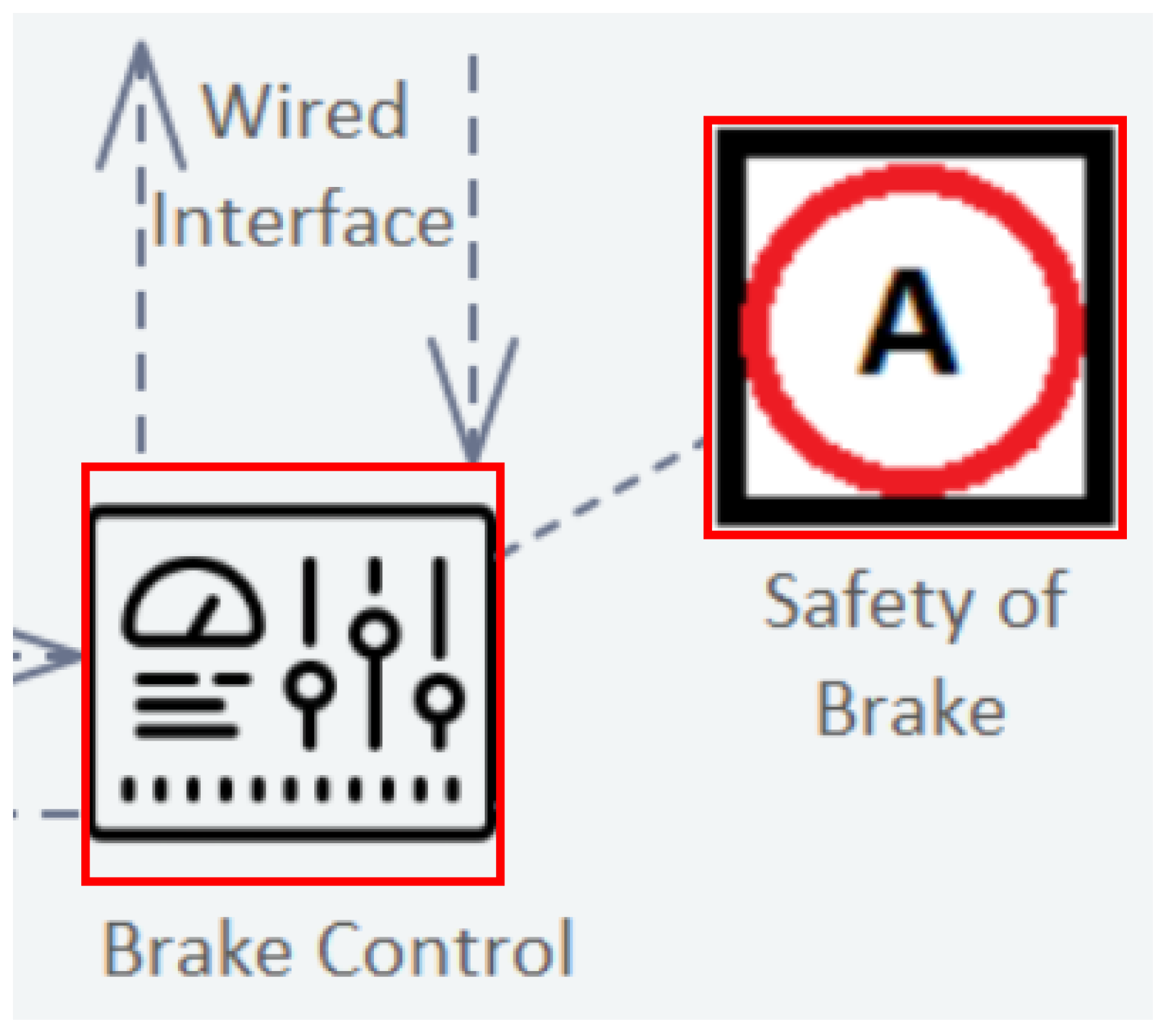
Asset: Availability of the Brake depicts that if an attacker gains control over the component holding the asset, they can disrupt the availability of the brake. It refers to the brake control becoming unavailable. This becomes relevant when the vehicle does a self-check at startup to verify that all vehicle control units are reachable. With regard to the availability of the brake, if e.g., the brake is not reachable the vehicle does not start. This could happen in case a trojan was placed within the vehicle network, thus, flooding the CAN Bus with messages. It is not required to take over a control unit, a simple blocking of the CAN Bus is sufficient. The availability of the brake was rated with an impact value of “Major”.
2.
Asset: Safety of the Brake describes an asset that may be affected by integrity breaches. In case an attacker disrupts the correct functionality of the brake, even for a short time, this might result in an accident. The attacker could wait until the driver intends to do an emergency braking and prohibit the action or they could wait until the car reaches a certain velocity and force an emergency braking. Both ways most likely result in an accident. Therefore, this asset was rated with the maximum impact level “Severe” which represents the maximum impact.
Of course, a TARA of a real-world architecture of a modern vehicle needs to consider more than two assets. However, for demonstration purposes, we limited the number of assets to reduce complexity.

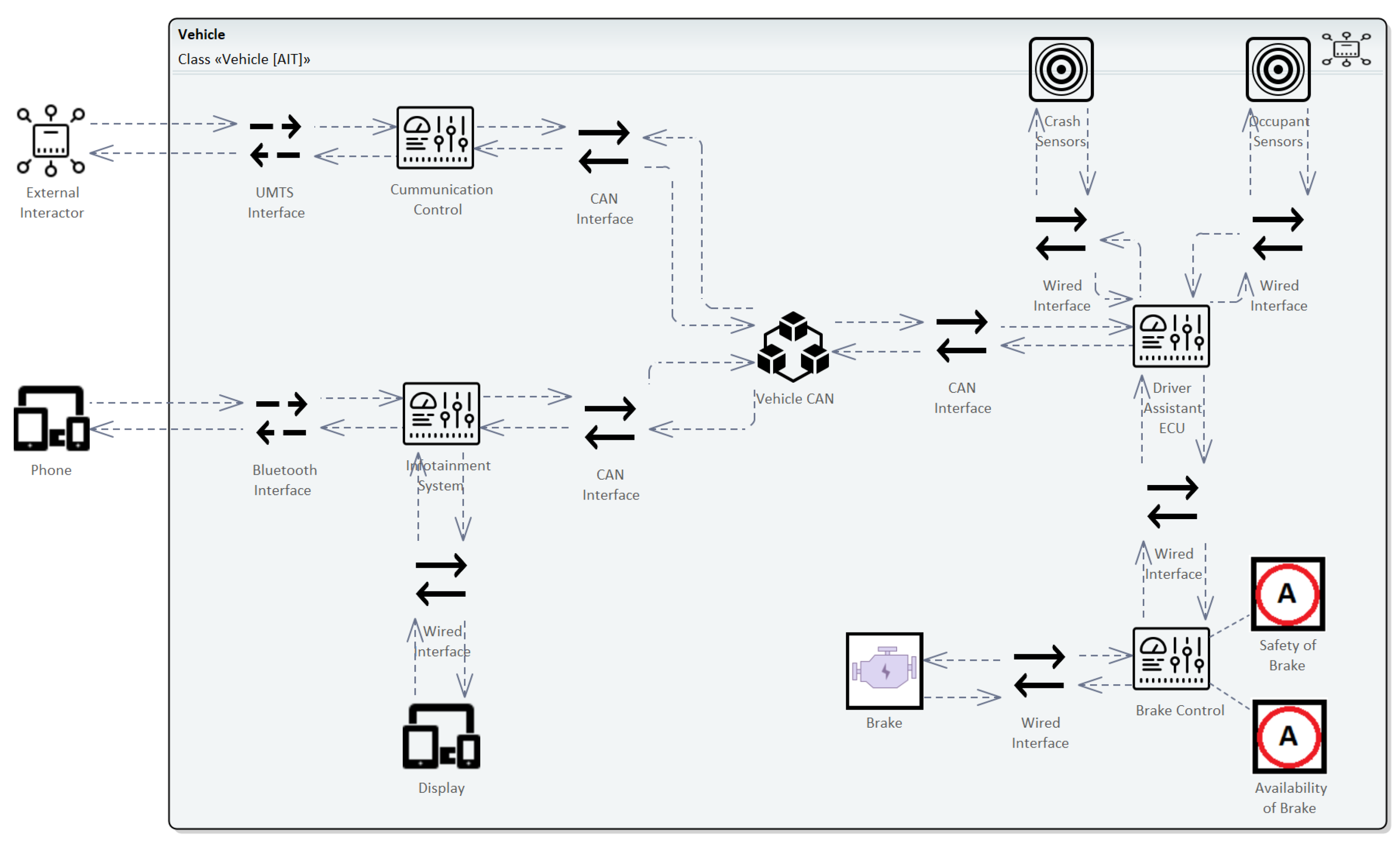
4.1.3. System Architecture

Based on the reference architecture from Figure 12 a system model for the braking control was designed with THREATGET. It contains all relevant components that are potentially involved in a remote attack targeted at the availability and safety of the brake assets as described above. This system model is shown in Figure 13.
The model shows a vehicle system that provides a cellular (UMTS) interface to communicate with other vehicles and the infrastructure as well as a Bluetooth interface to pair with a phone. As the phone, as well as the external interactor, are not part of the vehicle they are modeled as external components. The interfaces are connected to ECUs, the communication control takes care of managing communication with components from the outside, and the infotainment system is connected to a display for presenting information to the driver. Behind the ECUs lies a CAN Bus (Vehicle CAN) which is used for distributing information to various other components inside the vehicle. Please note that the CAN Bus is usually connected to more components than are displayed here. They were left out in order to reduce complexity, as they are not relevant to the excerpt of the analysis presented in this paper. Behind the CAN Bus lies the driver assistant ECU, which processes sensor data, and brings it in relation to data from the CAN Bus informing the brake control. Finally, the brake control which is responsible for the brake actuator represents the component holding the assets that need to be protected. The presented example serves as the basis for the analysis conducted with THREATGET. The following section elaborates on the results of the automated analysis process of THREATGET.

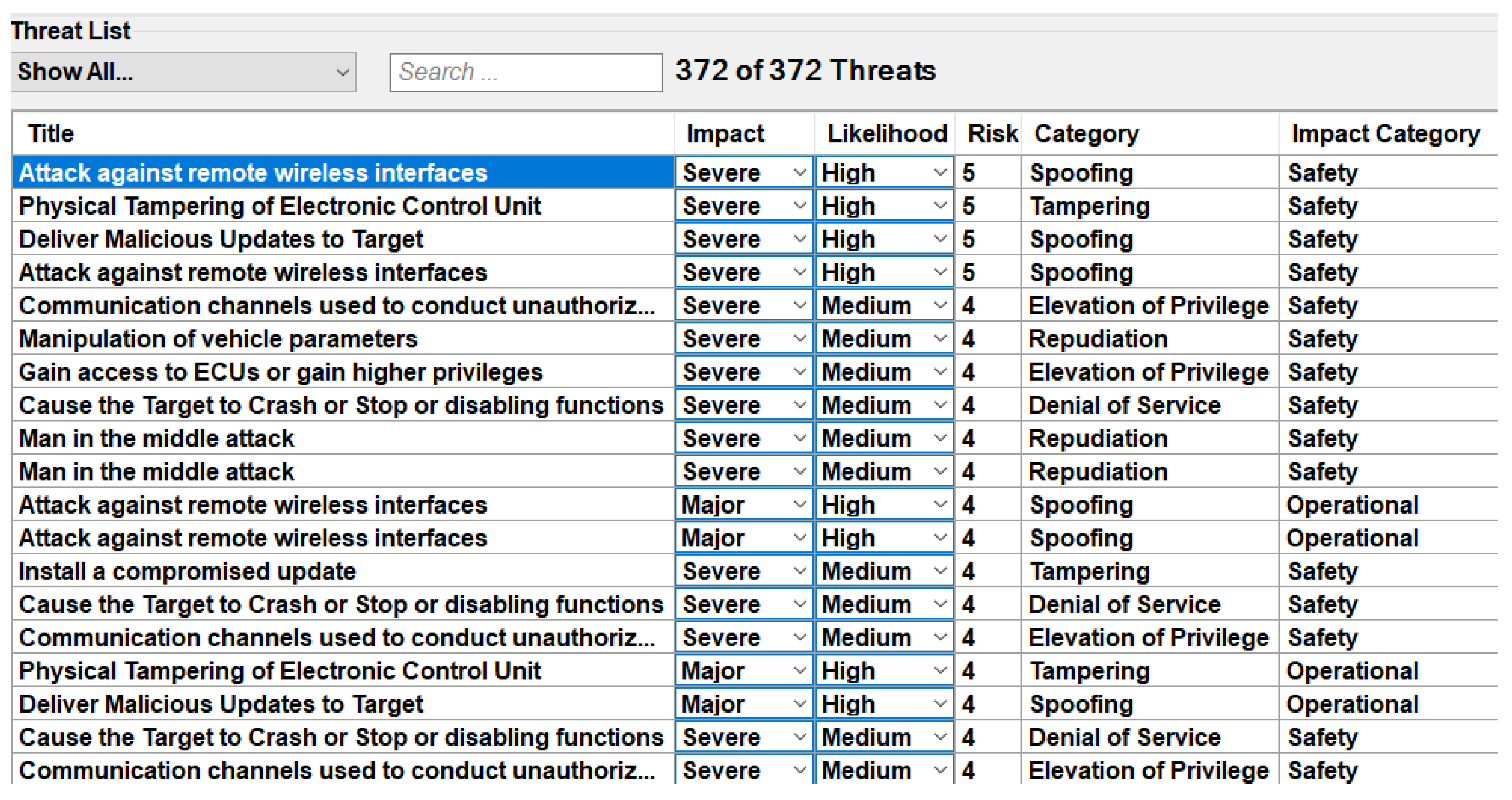
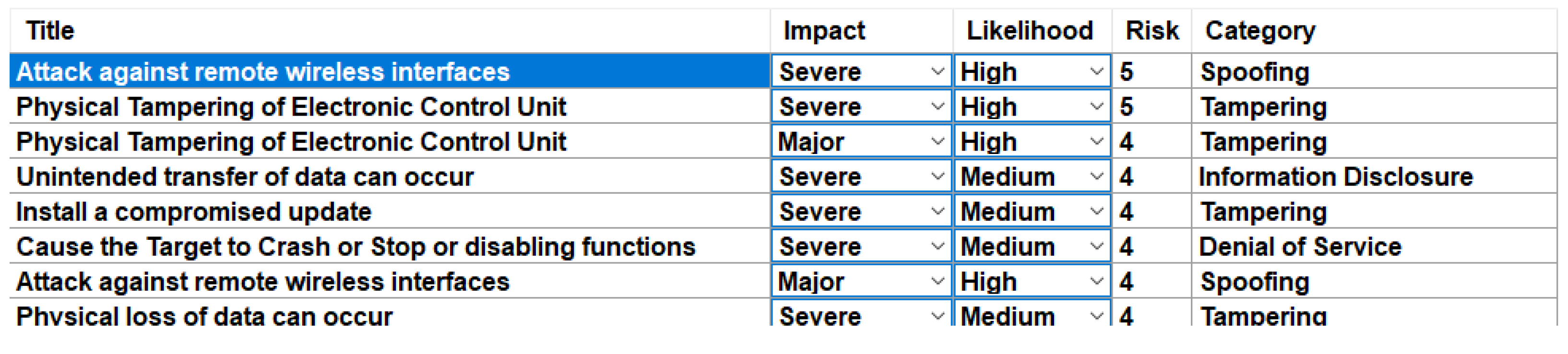
4.1.4. Identification of Threats

As described in Section 3, THREATGET’s analysis process compares the system model as well as the threat model to identify threats posed to the SuC. In case a pattern described in the threat model is found within the system model, a new entry is added to the threat catalog which is the result of the analysis process. The threat model itself is created beforehand. It is based on expert knowledge from the automotive domain as well as inputs from e.g., UNECE WP29, ETSI, and the Automotive Information Sharing Analysis Center (Auto-ISAC) with regard to community available threat information. This basis was also used to analyze the system model described in the previous section. Figure 14 displays an excerpt of the resulting threat catalog.
In total, 372 threats were identified. They range from attacks against wireless interfaces, towards tampering of ECUs, compromised or malicious updates to man-in-the-middle attacks. For demonstration purposes, no dedicated security measures were implemented into the system model. Countermeasures such as authentication, authorization, tamper protection, or input sanitization can be added to the system model, thus reducing the number of threats detected. In case a pattern defined in the threat model is found multiple times within the system model (e.g., multiple ECUs or multiple connections to a CAN Bus) this threat is added multiple times to inform the user about all potential weak spots.
All threats in the threat catalog possess their own automated impact and likelihood suggestions. While the impact is derived from attributes in the asset, the likelihood is currently based on expert knowledge. However, in case the cybersecurity expert considers them more or less critical, they can override these suggestions. The calculated risk is based on the standard matrix from ISO/SAE 21434 and can be deduced from the impact and likelihood levels. Categorization threats have a STRIDE category assigned to them. Finally, threats that involve an asset (i.e., damage scenarios) also have an impact category assigned to them.
Besides listing threats, THREATGET is capable of associating the threats with the system model. Examples are shown in Figure 15 and Figure 16.
The first threat is the wide-area wireless interfaces that enable an attacker to access the vehicle system. It is a threat that is based on the connection between two elements. Wireless interfaces and networks in the vehicle should be protected by strong authentication and authorization mechanisms. This would prevent an attacker from spoofing the identity of external communication partners and chaining a number of vulnerabilities together in order to gain remote access. As this threat is not associated with an asset, its THREATGET considers its impact as negligible. However, a wide area wireless interface is open for communication with the outside and can be easily reached. Therefore, the likelihood is considered high.
The second threat considers malicious updates to the target. It is about spoofing the source in order to send malicious updates. Therefore, updates should be secured and the component should be managed. Moreover, malware protection measures should be taken into account. This threat is associated with an asset and may lead to a damage scenario. The safety of the brake is rather critical. Consequently, an impact level of severe is assigned. Due to the fact that updates are not an uncommon attack vector, the likelihood is considered high. This leads to a maximum risk level and presents a risk that must be treated.
The same threat also applies to another asset mentioned before—the availability of the brake. However, the impact is somewhat lower as it does not necessarily lead to accidents. Therefore, the impact is considered major and the risk remains lower.
In order to reduce the overall risk, countermeasures can be assigned to the components as well as the connectors. Therefore, we applied authentication, authorization, input validation, and input sanitization measures to the wireless interfaces (UMTS and Bluetooth) which already reduces the amount of the highest-rated threats. Moreover, the total amount of threats is reduced by 20. These simple measures already have a potent effect on overall security. A small expert of the resulting threat catalog is displayed in Figure 17.
This section presented a selection of a few threats detected by THREATGET. Knowing about potential threats and being able to mitigate them is only one part of the problem. Chaining threats together is the next step in understanding attack patterns and making our systems more resilient.

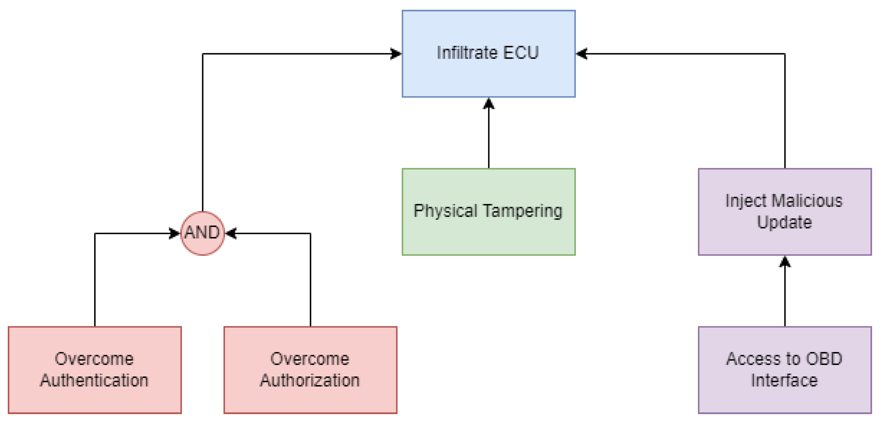
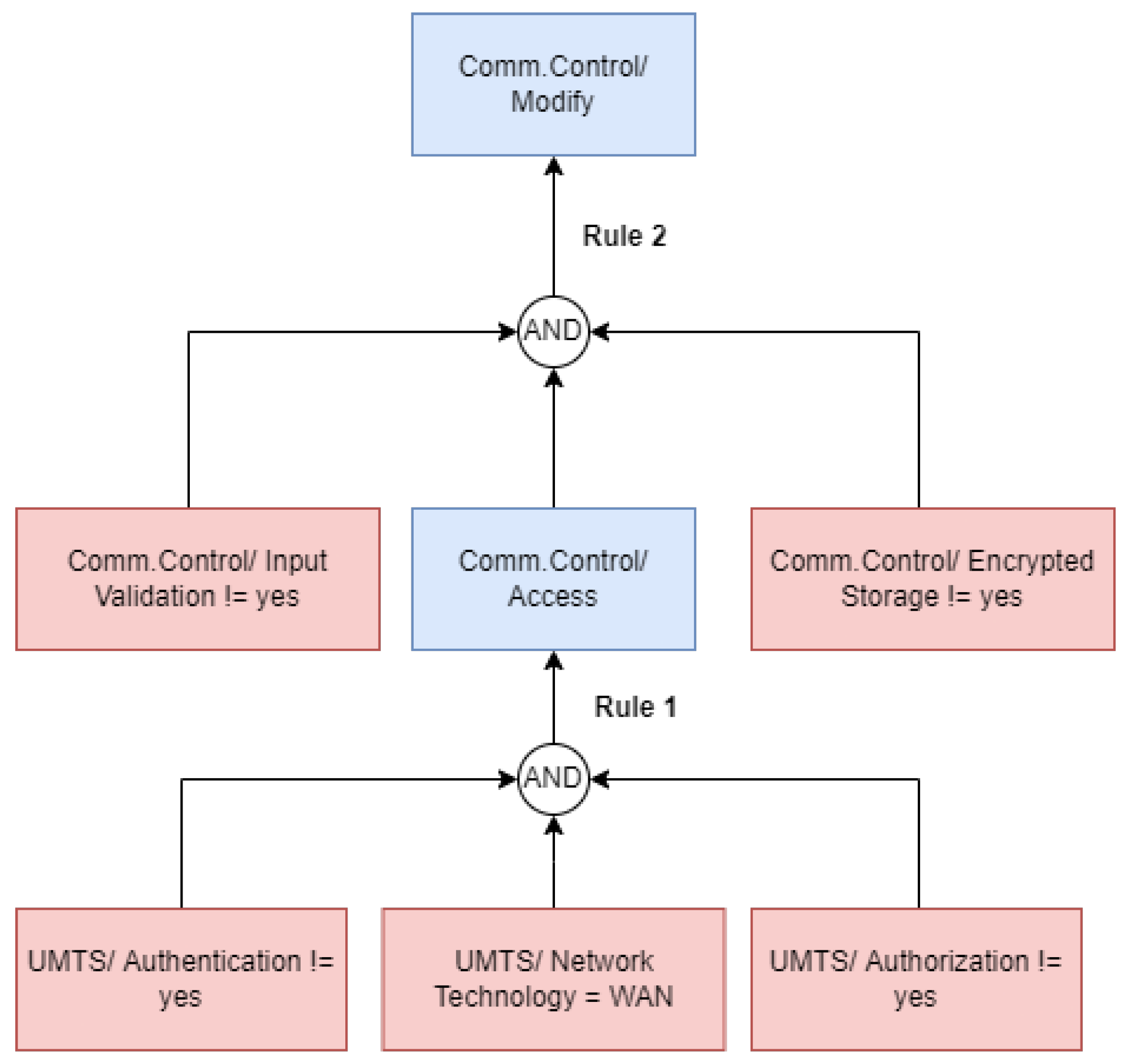
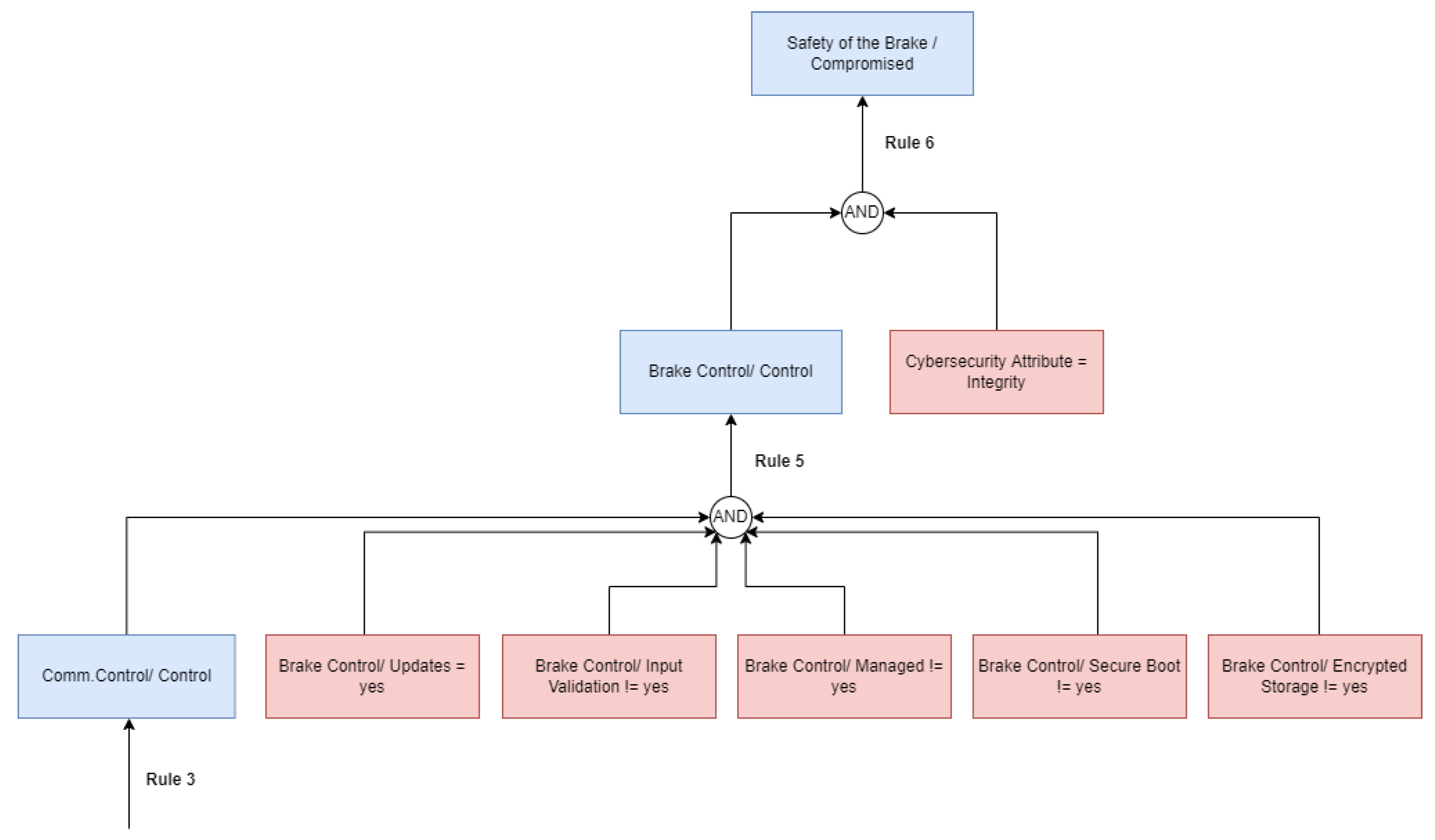
4.1.5. Identification of Attack Scenarios—Attack Trees

As explained in Section 3.2, our approach towards automatically generating attack trees involves the combination of individual attack steps. Therefore, we demonstrate a cyberattack scenario affecting the assets of the brake controls. The attack is based on a remote access scenario that starts from the external interactor with the vehicle via the UMTS Interface. Please note that full-featured attack trees can get very large in size, therefore, this paper focuses on two sub-trees to explain the concept behind generating them. The involved rules (anti-patterns) are defined in Appendix A.1.
The tree shown in Figure 18 describes the initial intrusion into the vehicle. The UMTS interface serves as the entry point as it has neither authentication nor authorization mechanisms applied. Furthermore, the fact that it is a wide area wireless interface makes it a potential target for remote attacks. Consequently, an attacker gains access to the communication control unit which is also the postcondition for this attack step. In the following, the access capability serves as means to intrude further into the system, therefore, it becomes our precondition or prerequisite for the subsequent attack step. As before the conditions for the next anti-patterns are fulfilled as there is no input validation or encrypted storage implemented. Thus, the attacker gains modify capabilities on the communication control. Rule 1 and Rule 2 and the following rule numbers refer to the number of the applied anti-patterns described in Appendix A.1. (Please note that Rule 4 is not described here, as it is not present in the excerpts of the attack trees that we show here. However, its description is contained in Appendix A.1.)
Rule 3 describes even higher capabilities on the communication control that can be gained by the attacker if modify rights have already been achieved. If the element allows updates, is not managed, and does not support secure boot, an attacker may gain full control over this component by uploading software.
Rule 5 describes another possible way to reach an asset and uses the manipulation of ECUs by malicious updates. The driver assistant ECU can be reached via the CAN Bus and the brake control may be reached if no anomaly detection is present. Consequently, a malicious update can be installed as the security properties as depicted in Rule 5 are not satisfied. Therefore, the attacker gains control over the driver assistant ECU.
Finally, Rule 6 ends in the control of the brake control unit, and, therefore, the integrity of the brake and consequently, the safety of the brake is compromised. The sub-tree involved in Rule 5 and Rule 6 is illustrated in Figure 19. Control over the communication unit has been gained via Rule 3.

5. Results

As demonstrated in Section 4, chaining together results from rules alongside the concept of prerequisites and postconditions enables the generation of attack trees. We also demonstrated how we are able to automate an ISO/SAE 21434-compliant TARA process with our methodology. This extends the automation above existing threat modeling tools and methods and represents the first automated generation of attack trees and attack paths based on a conceptual model. Therefore, our approach is applicable during design and concept time and individual attack steps towards reaching the attack target can be thoroughly analyzed. Consequently, informed decisions on risk treatment can be made and countermeasures may be applied to the system. The proper listing of security attributes in relation to the affected components within the tree allows for the identification of vulnerabilities within the system. Thus, THREATGET provides a vital contribution to the risk management process and gives information on which security measures need to be applied in the SuC. Moreover, these security measures can also be configured within the system model which leads to different results for the attack tree, as well as the threat analysis. This way, improved resilience can be achieved. In the automotive domain, with an increasing trend toward security regulation, automated approaches are required to achieve sufficient risk management and repeatable results. We compared the results of the THREATGET application in various real-world projects and while we did not achieve 100% coverage, this was the case in both directions. In six parallel applications on different automotive systems (e.g., experts analyzed the system and THREATGET analyzed the system) each part did detect 4–5% additional weaknesses. In the case of THREATGET, these additional results were used to add or extend rules to ensure coverage in the future. Regarding efficiency and timing, automation did offer a benefit and produced results that were easier to maintain and reuse.

6. Discussion

In this article, we highlighted cybersecurity as a core aspect of interconnected cars and infrastructures. We investigated various threat modeling methods and explored the origin of attack trees and attack graphs which come from research projects such as EVITA, OVERSEE, and HEAVENS. Furthermore, future vehicles need to fulfill cybersecurity standards and regulations (ISO/SAE 21434 and UNECE WP29) which enforce cybersecurity by design approaches. We described how AIT’s THREATGET tool can support the secure development of the various ECUs and their connections within a car by applying security by design principles but also how it can be used to support the threat identification and threat analysis of existing systems in order to fulfill the requirements from standards and regulations. Furthermore, THREATGET provides superior analysis capabilities to common threat modeling tools. By using its flow pattern it can identify complete attack paths within a system model in contrast to current STRIDE per element and STRIDE per interaction approaches which focus on single elements or the direct connection between only two elements. With the application of attack trees and attack graphs, THREATGET has even more advanced capabilities to identify the most likely and most dangerous (in terms of their potential consequences) paths an attacker could take in the system as well as to estimate the potential damage that can be done to the car (and, of course, the people inside it). Past approaches rely on a manual derival of attack trees based on the system architecture. Therefore, we introduced the first approach towards an automated generation of attack graphs on the system level. By incorporating anti-patterns for threat identification alongside the concept of pre- and postconditions to model attacker capabilities, we can describe a chain of attacks and concatenate them into attack paths which are stored within an attack graph. By specifying the target node, all identified attack paths can be extracted from this attack graph and arranged within an attack tree. Finally, we demonstrated this in a real-world use case.
These aspects analyzed by THREATGET can directly be integrated into a full risk assessment and risk management approach such as TVRA or TARA as mentioned in Section 2.2.2 and Section 2.2.3. In this way, THREATGET supports Step 3 to Step 6 of TVRA and all steps of TARA, as we showed in our small example in Section 4. Hence, THREATGET is particularly useful when implementing TARA, since the modeling component on the one hand covers the first three steps of TARA, i.e., the identification of assets together with their impacts, and on the other hand provides the system architecture as a direct output. Furthermore, THREATGET delivers a complete set of potential threats and consequently also attack scenarios due to its automated threat assessment. Moreover, the automated attack tree analysis then paves the way for an attack feasibility estimation by showing the most probable attack paths (and the ones with the highest impact on various assets); this information is then used to calculate the risk, i.e., the final step in the TARA process. As part of our future work, we will focus on a more intuitive procedural integration of the THREATGET tool and also strengthen the relations to TVRA.
Another aspect that we will be looking at in the future is targeted towards a more holistic analysis and is even going beyond attack graphs, rather focusing on potential cascading effects that can occur in the system as a consequence of a specific attack. In this context, the main focus is not the valuable asset that has been defined in the model or the activities taken by the adversary to reach that asset (i.e., the attack graph) but the elements and assets that are connected to—and thus depending on—the attacked asset. We will inspect how a compromise or a malfunction of the attacked asset will affect the other parts of the system. Hence, this analysis does not only take into account the direct impact an attack has on the asset but provides a more holistic overview. In other words, by analyzing all the elements and assets affected by the cascading effects, the impact on the overall system can be evaluated in a more suitable way. This will then further support the risk assessment and risk management approaches such as TVRA and TARA and give the security experts a more detailed overview.

7. Patents

A European patent “VERFAHREN ZUR ERMITTLUNG VON KRITISCHEN SCHWAC HSTELLENKETTEN” on automated attack tree generation was submitted and is currently undergoing evaluation.

Author Contributions

Conceptualization, S.C., C.S. and A.M.S.; methodology, all; software, S.C. and K.C.; validation, S.C., K.C. and C.S.; formal analysis, K.C. and S.S.; investigation, S.C. and C.S.; resources, all.; writing—original draft preparation, S.C., K.C. and A.M.S.; writing—review and editing, C.S., S.S. and M.L.; visualization, S.C.; supervision, C.S. All authors have read and agreed to the published version of the manuscript.

Funding

Part of this work has been performed in the VALU3S project, which has received funding from the ECSEL Joint Undertaking (JU) program under Grant Agreement No. 876852.

Data Availability Statement

Not applicable.

Acknowledgments

The authors would like to thank Thorsten Tarrach, who substantially contributed to the development of attack trees during his time at AIT.

Conflicts of Interest

The authors declare no conflict of interest.

Abbreviations

The following abbreviations are used in this manuscript:
AITAustrian Institute of Technology
CCAMCooperative Connected and Automated Mobility
CANController Area Network
CIAConfidentiality, Integrity, Availability
C-ITSCooperative Intelligent Transport System
CPSCyber–Physical System
CSMSCybersecurity Management System
DDoSDistributed Denial of Service
DFDData-Flow Diagram
DSLDomain Specific Language
DREADDamage Potential, Reproducibility, Exploitability, Affected Users, and Discoverability
ECUElectronic Control Unit
EDFDExtended Data-Flow Diagram
ETSIEuropean Telecommunications Standards Institute
EVITAE-safety vehicle intrusion protected applications
OBDOn-Board Diagnostics
GPSGlobal Positioning System
HEAVENSHEAling Vulnerabilities to ENhance Software Security and Safety
ISOInternational Standardization Organization
OEMOriginal Equipment Manufacturer
OVERSEEOpen VEhiculaR SEcurE platform
SAESociety of Automotive Engineers
SuCSystem Under Consideration
STRIDESpoofing, Tampering, Repudiation, Information Disclosure, Denial of Service, and Elevation of Privilege
TARAThreat Analysis and Risk Assessment
TVRAThreat, Vulnerability, and Risk Assessment
UMTSUniversal Mobile Telecommunications System
UNECEUnited Nations Economic Commission for Europe

Appendix A

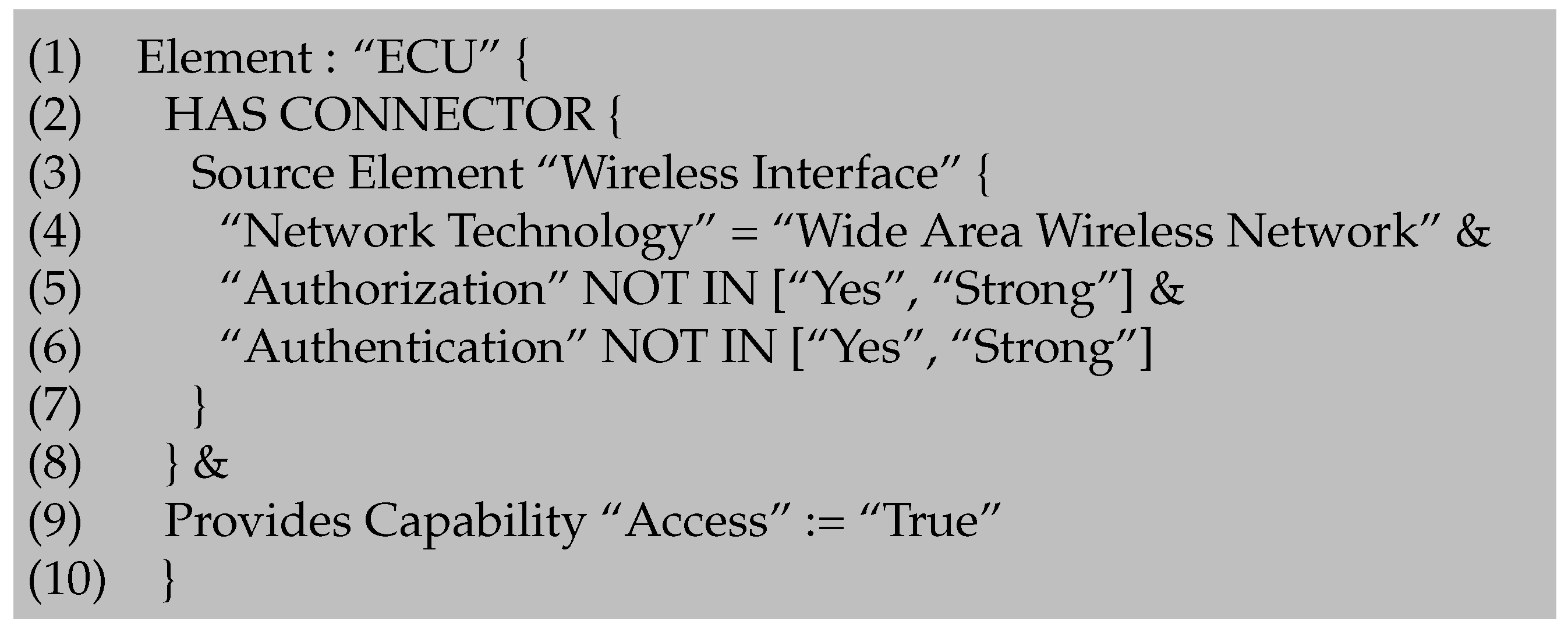
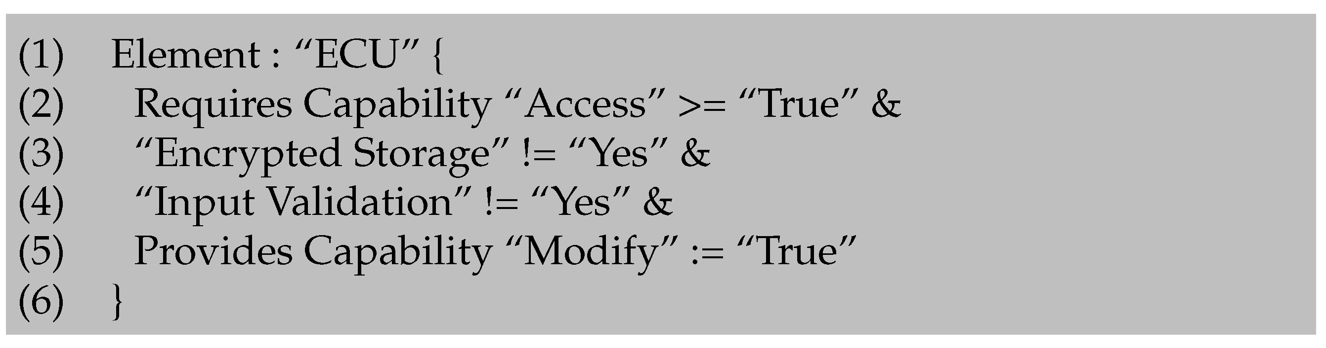
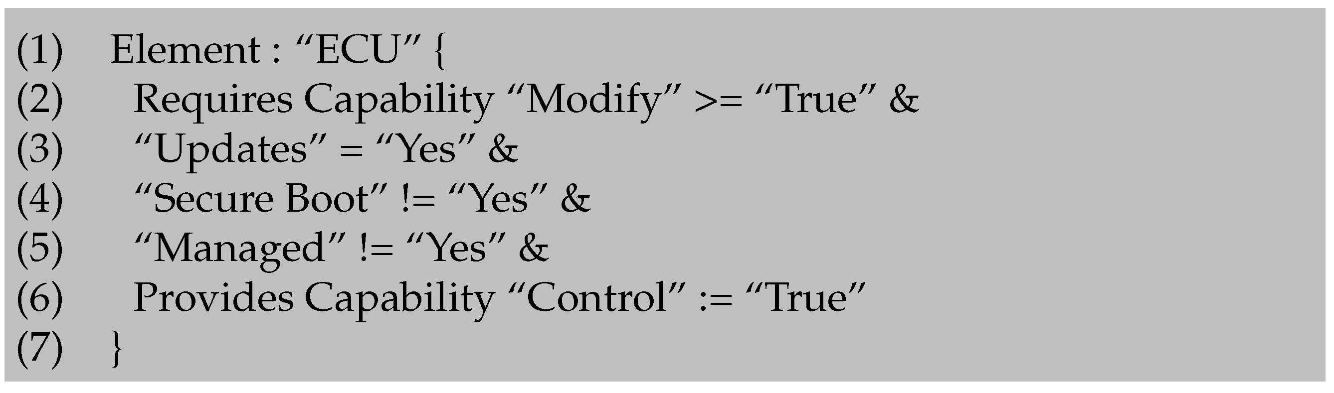
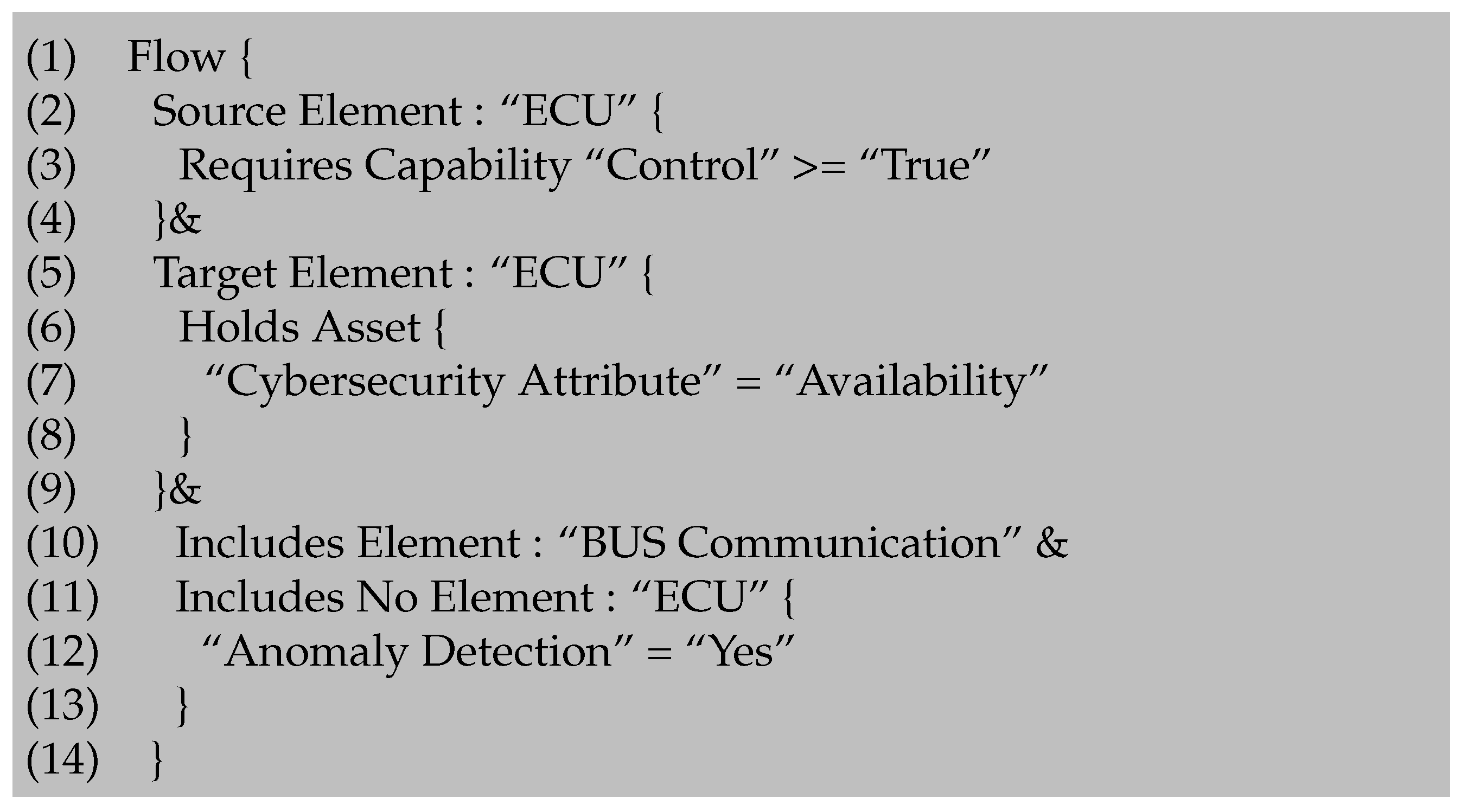
Appendix A.1. Attack Tree Rules

In this section, we present the identified threats for the system described above. We will use the example from the international standard ISO/SAE 21434. The respective threats are briefly described in each case and then we go into detail on how the threats can be represented as anti-patterns in order to be able to use them for the automatic analysis.
Each rule builds on the previous one, as together they describe multiple attack paths to affect the brake actuator, its controlling ECU, and the associated assets. The relationship between the rules is established through the requires capability and provides capability filters, as described earlier.
A capability describes one or more “abilities” of an attacker on a particular component of the system.
For this example, we have identified three capabilities: “Access”, “Modify” and “Control”. Each of these capabilities can take the following three values: “undefined”, “false”, or “true”.
The “Access” capability describes that the attacker has access to a component, i.e., that data can be exchanged with the component.
With the “Modify” capability, we describe that data can not only be exchanged but also that data of the component can be changed within the system.
Finally, the “Control” capability shows that an attacker has achieved full control over a component and can thus influence the system through it.
Since the anti-patterns are more complex and longer than the previous simple examples, the individual lines are numbered. Within the description, we refer to the respective lines of the anti-pattern with numbering. Since some parts of the anti-patterns are repetitive, we refrain from explaining them repeatedly.
The first anti-pattern in Figure A1 checks whether there is an ECU within the system that receives input from a wireless interface, which could give the attacker access to this ECU.
Figure A1. Anti-Pattern for Rule 1.
Information 14 00014 g0a1
Line (1) initiates the anti-pattern with an element pattern that examines all “ECU”s of the system.
In lines (2–8), it is examined whether the “ECU” has a connector (2), which originates from a “Wireless Interface” (3).
In addition, three attributes of this interface are examined (4–6).
It is checked whether the interface has the attribute “Network Technology” with the set value “Wide Area Wireless Network” (4), as this threat targets, for example, the UMTS interface of the vehicle.
Furthermore, this anti-pattern verifies that the interface does not have a simple or strong “Authorization” (5) mechanism or an “Authentication” (6) mechanism.
If these mechanisms are not implemented in any way, it would be possible for an attacker to abuse this interface to send malicious data to the vehicle.
This line (7) concludes the description of the “Wireless Interface” and line (8) the description of the connector between the “ECU” and the interface.
In line (9), we describe the first capability filter. This indicates that the attacker is assigned the capability named “Access” with the value “True” for the “ECU” component if this anti-pattern is completely valid. The last line (10) closes the element pattern.
The second anti-pattern in Figure A2 also focuses on an ECU within the system and builds on the first one. In this case, it checks whether the attacker can make use of the access capability to the ECU to modify the data on the ECU component by exploiting the memory or non-existent/faulty input validation.
Figure A2. Anti-Pattern for Rule 2.
Information 14 00014 g0a2
In the first line (1), the element pattern is again specified with a focus on the “ECU”.
In the second line (2), it is checked whether the attacker already has the “Access” capability on this “ECU”. This line refers to the previous anti-pattern, as this threat requires some kind of connection between the adversary and the “ECU” component.
In lines (3–4), the “Encrypted Storage” (3) and “Input Validation” (4) attributes of the “ECU” are examined. In both cases, it is checked whether the value is not equal to “Yes”.
If this is the case, the attacker obtains the capability “Modify” on this “ECU” as described in line (5) by the provided capability filter. This filter provides the attacker with an additional capability that can be used in the following steps.
This is due to the fact that the attacker can upload data to the “ECU” and the data is not inspected and the data can be stored within the “ECU” as no encryption is necessary.
Line (6) closes this anti-pattern.
In the third anti-pattern in Figure A3, we again focus on the ECU in order to validate that the attacker is able to gain full control over this component. For this, the attacker needs the capability to modify this component. In addition, it must be possible to update the component, and, furthermore, it must be possible for the attacker to exploit this update process in order to install malicious software and thus gain control over the component.
Figure A3. Anti-Pattern for Rule 3.
Information 14 00014 g0a3
Line (2) refers to the previous anti-pattern, as the attacker needs the capability to “Modify” the component to upload malicious data into the “ECU”. In lines (3–5), the anti-pattern focuses on additional properties of this “ECU”.
It is analyzed whether it is possible to “Update” the “ECU” (3), as this allows the attacker to install malicious software.
Secondly, it is checked whether the “ECU” does not have a “Secure Boot” mechanism (4), meaning that modified software cannot be detected during the boot process.
Furthermore, this anti-pattern checks if the attribute “Managed” of the “ECU” is unequal to “Yes”. If this is the case, it is not regularly checked for faulty software or other impairments.
If these preconditions are met, then the attacker gains complete “Control” (6) over the “ECU” and can perform further attack actions through this corrupted “ECU”.
The following fourth threat displayed in Figure A4 now directly threatens the vehicle’s braking system, but can also affect other functionalities of the vehicle. The attacker uses the control over the corrupted ECU to flood the vehicle’s CAN BUS system with malicious forged CAN messages. The direct connection of the ECU to the BUS system allows the attacker to create his own messages and inject them into the system. By sending a large number of these messages, the system can collapse. This attack pattern is similar to a DDoS attack and can thus also paralyze the braking system and thus also affect passenger safety.
Figure A4. Anti-Pattern for Rule 4.
Information 14 00014 g0a4
Line (1) establishes a flow pattern. This pattern examines the system and the connectors between the components. However, it does not only examine direct connections but all connections and searches for a path between the defined source and target element. Not only the shortest path is examined, but every path that exists within the system. In this way, data flows between components can be examined.
Lines (2–4) define the source element of the flow.
This flow starts at an element of type “ECU” (2).
In addition, the attacker must already have gained the ability “Control” on this element (3). Line (4) concludes the specification of the source element. Lines (5–9) describe the target element of the flow. This flow pattern targets all other “ECU”s (5) associated with the source that has an asset or is associated with it (6), where the asset must be concerned about the “Availability” (7) represented by the asset’s “Cybersecurity Property”.
Line (8) completes the asset description and line (9) completes the flow pattern target description.
As described earlier, a flow pattern examines a path between a source and a destination. With an include filter as in line (10), we can check the elements within the observed path. When describing the threat, we found that the “ECU” can be used to send CAN messages, so this path must contain a “BUS Communication” element (10).
However, the flow should not contain an “ECU” type element (11) that is capable of performing “Anomaly Detection” (12). Otherwise, the system could detect that there is a large number of CAN messages that should not be in the system and could then shut down the “ECU” under the “Control” of the attacker.
The fifth anti-pattern in Figure A5 describes another threat that exists through an attacker-controlled ECU for the analyzed system. This threat targets the updated behavior of the overall system. Normally, an update is downloaded from the system via the UMTS interface and then rolled out to the individual ECU components. In this case, the attacker can exploit this behavior by injecting a malicious update into the system and installing it on all ECU components, thereby gaining control of these components. This threat is a synthesis of anti-patterns three and four.
Figure A5. Anti-Pattern for Rule 5.
Information 14 00014 g0a5
Similar to the fourth anti-pattern, a flow pattern (1) is used in Rule 5 to examine data communication starting from an “ECU” (2) under “Control” of the attacker (3) and a target “ECU” (5).
As described in the third threat, the target “ECU” must have the following attributes: (6) it must not have “Encrypted Storage”, (7) it must not implement an “Input Validation” mechanism, it must allow “Updates” (8), it must not implement “Secure Boot” (9) and it must be an “ECU” with the property “Managed” set unequal to “Yes”(10).
If all these properties apply, then the attacker also obtains the “Control” capability over any target “ECU” (11).
The communication must be via the vehicle’s CAN messaging system, so the path must contain an element “BUS communication” (13).
Finally, also in this case, no “ECU” within the path (14) may perform “Anomaly Detection” (15), otherwise, the update could not be carried out.
The sixth and final anti-pattern in Figure A6 we would like to present in this context relates to the assets linked to an ECU under the control of the attacker. If a system component comes under the control of the attacker, the integrity of assets can no longer be guaranteed, as the attacker may influence them. In this example, we want to point out that the attacker controls the brake control ECU and, in the worst case, changes the behavior of the brake.
Figure A6. Anti-Pattern for Rule 6.
Information 14 00014 g0a6
This anti-pattern focuses on any “ECU” within the system (1) that is under the control of the attacker (2).
It also checks whether this “ECU” is related or linked to an “Asset” (3) that focuses on the “Integrity” (4) of this specific “ECU”.

References

  1. Bradley, T. Cyber Attacks on Cars up 225 Percent: How Hackers Could be Targeting Your Vehicle. Section: Cars. 2022. Available online: https://www.express.co.uk/life-style/cars/1632500/hackers-target-drivers-cyber-attacks-cars (accessed on 15 August 2022).
  2. Blum, B. Cyberattacks on Cars Increased 225% in Last Three Years. 2022. Available online: https://www.israel21c.org/cyberattacks-on-cars-increased-225-in-last-three-years/ (accessed on 15 August 2022).
  3. 1 in 3 Automotive Cyber Incidents Result in Car Theft or Break-Ins—Atlas VPN. Available online: https://atlasvpn.com/blog/1-in-3-automotive-cyber-incidents-result-in-car-theft-or-break-ins (accessed on 16 August 2022).
  4. Schmittner, C.; Schrammel, B.; König, S. Asset Driven ISO/SAE 21434 Compliant Automotive Cybersecurity Analysis with ThreatGet. In Proceedings of the European Conference on Software Process Improvement, Krems, Austria, 1–3 September 2021; Springer: Berlin/Heidelberg, Germany, 2021; pp. 548–563. [Google Scholar]
  5. Schmittner, C.; Dobaj, J.; Macher, G.; Brenner, E. A preliminary view on automotive cyber security management systems. In Proceedings of the 2020 Design, Automation & Test in Europe Conference & Exhibition (DATE), Grenoble, France, 9–13 March 2020; IEEE: Piscataway, NJ, USA, 2020; pp. 1634–1639. [Google Scholar]
  6. Schmittner, C.; Tummeltshammer, P.; Hofbauer, D.; Shaaban, A.; Meidlinger, M.; Tauber, M.; Bonitz, A.; Hametner, R.; Brandstetter, M. Threat Modeling in the Railway Domain. In Proceedings of the International Conference on Reliability, Safety, and Security of Railway Systems, Lille, France, 4–6 June 2019; pp. 261–271. [Google Scholar]
  7. Shevchenko, N. Threat Modeling: 12 Available Methods. 2018. Available online: https://insights.sei.cmu.edu/sei_blog/2018/12/threat-modeling-12-available-methods.html (accessed on 14 December 2022).
  8. Lautenbach, A.; Islam, M. The HEAling Vulnerabilities to ENhance Software Security and Safety (HEAVENS) Project—Security Models. 2016. Available online: https://autosec.se/wp-content/uploads/2018/03/HEAVENS_D2_v2.0.pdf (accessed on 11 August 2022).
  9. Shostack, A. Threat Modeling: Designing for Security; Wiley: Indianapolis, IN, USA, 2014; OCLC: 855043351. [Google Scholar]
  10. Hamad, M. A Multilayer Secure Framework for Vehicular Systems; Technische Universität Braunschweig: Braunschweig, Germany, 2020. [Google Scholar]
  11. Khan, R.; McLaughlin, K.; Laverty, D.; Sezer, S. STRIDE-based threat modeling for cyber-physical systems. In Proceedings of the 2017 IEEE PES Innovative Smart Grid Technologies Conference Europe (ISGT-Europe), Torino, Italy, 26–29 September 2017; pp. 1–6. [Google Scholar] [CrossRef] [Green Version]
  12. The Ultimate Beginner’s Guide to Threat Modeling. Available online: https://shostack.org/resources/threat-modeling.html (accessed on 12 August 2022).
  13. Allen-Addy, C. Threat Modeling Methodology: TRIKE. Available online: https://www.iriusrisk.com/resources-blog/trike-threat-modeling-methodologies (accessed on 14 December 2022).
  14. Threatmodeler. Threat Modeling Methodologies: What is VAST? 2018. Available online: https://threatmodeler.com/threat-modeling-methodologies-vast/ (accessed on 14 December 2022).
  15. Smith, C. The Car Hacker’s Handbook: A Guide for the Penetration Tester; No Starch Press: San Francisco, CA, USA, 2016. [Google Scholar]
  16. Shaaban, A. An Ontology-Based Cybersecurity Framework for the Automotive Domain-Design, Implementation, and Evaluation. Ph.D. Thesis, Faculty of Computer Science, University of Vienna, Vienna, Austria, 2021. Available online: https://utheses.univie.ac.at/detail/59948 (accessed on 17 August 2022).
  17. Goswami, D.; Schneider, R.; Masrur, A.; Lukasiewycz, M.; Chakraborty, S.; Voit, H.; Annaswamy, A. Challenges in automotive cyber-physical systems design. In Proceedings of the 2012 International Conference on Embedded Computer Systems (SAMOS), Samos, Greece, 16–18 July 2012; IEEE: Piscataway, NJ, USA, 2012; pp. 346–354. [Google Scholar]
  18. Pauker, F.; Mangler, J.; Rinderle-Ma, S.; Pollak, C. Centurio. work-modular secure manufacturing orchestration. In Proceedings of the 16th International Conference on Business Process Management 2018, Sydney, Australia, 9–14 September 2018. [Google Scholar]
  19. AVL. Automotive Cybersecurity—A Holistic Approach to the Protection of Vehicles. 2020. Available online: https://www.avl.com/web/guest/services1/-/asset_publisher/gYjUpY19vEA8/content/automotive-cyber-security (accessed on 10 October 2020).
  20. EVITA. E-Safety Vehicle Intrusion Protected Application—FINAL DRAFT. 2008. Available online: https://trimis.ec.europa.eu/sites/default/files/project/documents/20130702_175923_78998_EVITA_ProjectSummary.pdf (accessed on 15 August 2022).
  21. OVERSEE. The Application Store for Cars: Secure Download of Your Favorite Apps into Your Car. 2010. Available online: https://www.oversee-project.com/fileadmin/oversee/press_releases/OVERSEE-Pressrelease-1-EN.pdf (accessed on 15 August 2022).
  22. Olsson, M. HEAling Vulnerabilities to ENhance Software Security and Safety. 2016. Available online: https://www.vinnova.se/globalassets/mikrosajter/ffi/dokument/slutrapporter-ffi/elektronik-mjukvara-och-kommunikation-rapporter/2012-04625eng.pdf (accessed on 15 August 2022).
  23. J3061_202112; Cybersecurity Guidebook for Cyber-Physical Vehicle Systems. SAE International: Warrendale, PA, USA, 2021.
  24. ISO/SAE 21434 Road; Vehicles—Cybersecurity Engineering. ISO—International Standardization Organization: Geneva, Switzerland, 2021.
  25. ETSI. Intelligent Transport Systems (ITS); Security; Threat, Vulnerability and Risk Analysis (TVRA); Technical Report; European Telecommunications Standards Institute (ETSI): Sophia, France, 2010. [Google Scholar]
  26. UNECE, U.N.E.C.f.E. Draft New UN Regulation on Uniform Provisions Concerning the Approval of Vehicles with Regard to Cyber Security and of Their Cybersecurity Management Systems. 2020. Available online: https://unece.org/DAM/trans/doc/2020/wp29grva/GRVA-05-05r1e.pdf (accessed on 25 February 2020).
  27. Microsoft. Microsoft Threat Modeling Tool Getting Started Guide, Microsoft Trustworthy Computing. 2016. Available online: https://download.microsoft.com/download/4/F/D/4FDDEA98-4ABD-47A7-AA0E-815CE8660A76/Threat%20Modeling%20Tool%202016%20Getting%20Started%20Guide.docx (accessed on 20 December 2022).
  28. Microsoft. Microsoft Threat Modeling Tool User Guide, Microsoft Trustworthy Computing. 2016. Available online: https://download.microsoft.com/download/4/F/D/4FDDEA98-4ABD-47A7-AA0E-815CE8660A76/Threat%20Modeling%20Tool%202016%20User%20Guide.docx (accessed on 20 December 2022).
  29. Eng, D. Integrated Threat Modelling. Master Dissertation, Universitetet i Oslo, Oslo, Norway, 2017. [Google Scholar]
  30. Wolf, M. Combining Safety and Security Threat Modeling to Improve Automotive Penetration Testing. Master’s Thesis, Universität Ulm, Ulm, Germany, 2019. [Google Scholar]
  31. OWASP Threat Dragon | OWASP Foundation. Available online: https://owasp.org/www-project-threat-dragon/ (accessed on 18 July 2022).
  32. Williams, I.; Yuan, X. Evaluating the effectiveness of Microsoft threat modeling tool. In Proceedings of the 2015 Information Security Curriculum Development Conference on—InfoSec ’15, Kennesaw, Georgia, 15–17 November 2015; ACM Press: Kennesaw, Georgia, 2015; pp. 1–6. [Google Scholar]
  33. Christl, K.; Tarrach, T. The analysis approach of ThreatGet. arXiv 2021, arXiv:2107.09986. [Google Scholar] [CrossRef]
  34. Jang-Jaccard, J.; Nepal, S. A survey of emerging threats in cybersecurity. J. Comput. Syst. Sci. 2014, 80, 973–993. [Google Scholar] [CrossRef]
  35. Navarro, J.; Deruyver, A.; Parrend, P. A systematic survey on multi-step attack detection. Comput. Secur. 2018, 76, 214–249. [Google Scholar] [CrossRef]
  36. Paul, S. Towards Automating the Construction & Maintenance of Attack Trees: A Feasibility Study. Electron. Proc. Theor. Comput. Sci. 2014, 148, 31–46. [Google Scholar]
  37. Lallie, H.S.; Debattista, K.; Bal, J. A review of attack graph and attack tree visual syntax in cyber security. Comput. Sci. Rev. 2020, 35, 100219. [Google Scholar] [CrossRef]
  38. Schneier, B. Academic: Attack Trees—Schneier on Security. 1999. Available online: https://www.schneier.com/academic/archives/1999/12/attack_trees.html (accessed on 20 December 2022).
  39. Shanker, S. Enhancing Automotive Embedded Systems with FPGAs. Ph.D. Thesis, Nanyang Technological University, Singapore, 2016. [Google Scholar] [CrossRef]
Figure 1. An illustration of the threat modeling process based on [6].
Information 14 00014 g001
Figure 2. ETSI TVRA method steps.
Information 14 00014 g002
Figure 3. Data Flow Diagram (DFD) (left) vs. Extended Data Flow Diagram (EDFD) (right).
Information 14 00014 g003
Figure 4. An example for an anti-pattern.
Information 14 00014 g004
Figure 5. Example model to demonstrate attack flows.
Information 14 00014 g005
Figure 6. An example for a flow anti-pattern.
Information 14 00014 g006
Figure 7. STRIDE per interaction example.
Information 14 00014 g007
Figure 8. Attack path derived from flow anti-pattern.
Information 14 00014 g008
Figure 9. An exemplary attack tree showing how to infiltrate an ECU.
Information 14 00014 g009
Figure 10. Concept of an attack tree vs. attack graph.
Information 14 00014 g010
Figure 11. Attack graph generation algorithm.
Information 14 00014 g011
Figure 12. An automotive reference architecture as presented in [39].
Information 14 00014 g012
Figure 13. Diagram of the automotive system architecture including assets.
Information 14 00014 g013
Figure 14. Automatically assessed threats based on the system architecture.
Information 14 00014 g014
Figure 15. Threat over cellular interface.
Information 14 00014 g015
Figure 16. Threat regarding brake control.
Information 14 00014 g016
Figure 17. Excerpt of the threat catalog after updating security measures.
Information 14 00014 g017
Figure 18. Sub-tree for gaining modification capability.
Information 14 00014 g018
Figure 19. Sub-tree for reaching the safety of the brake asset.
Information 14 00014 g019
Table 1. Other available threat modeling methods and risk rating schemes [7,12,13,14].
MethodShort DescriptionDiscussion
PASTA
  • For identification of countermeasures
  • Eases prioritization of threats
  • Multi-stage process
  • Attacker-centric
PASTA requires a strict and weighty process while STRIDE is mainly used for the identification of threats and countermeasures as part of a process. The approach that will be presented remains flexible and can be used in all development phases, even when new objectives or requirements are introduced.
LINDDUN
  • Focuses mainly on privacy
  • Based on DFD
  • Related to STRIDE
LINDDUN is targeted at privacy. For our use case, a more generic approach also including operational, safety, and financial aspects is required.
OCTAVE
  • Targeted at organizational risks
  • Does not consider technological risks
Technological risks represent the main focus of our methodology. However, organizational risks may be deduced.
TRIKE
  • Security audit framework
  • Based on DFD
  • Two categories—elevation of privilege and denial of service
This method focuses mainly on IT and auditing and is, therefore, not suitable for our application field.
VAST
  • Automated tool for threat identification
  • Requires specific software
  • Scalable process
In contrast to a generic approach, VAST is targeted at processes on the organizational level and large-scale IT systems.
Persona non Grata
  • Focuses on human attackers
  • Describes characteristics and skills
  • Helps understand attacker perspective
Persona non Grata is a manual method and does not include potential automated propagation of attacks throughout the system.
CVSS
  • Represents a scoring system based on multiple attributes
  • Can be used by threat modeling methods to rate risks
Represents a method for rating potential risks but not for the identification of threats or mitigation measures. However, it incorporates a detailed scheme for assigning a score to certain threats and will, therefore, be considered for integration with our method in the future.
DREAD
  • Is a risk rating method
  • Used for risk evaluation
  • Helps prioritization of risks
Like CVSS, DREAD represents a scoring system to classify the criticality of threats. However, when it comes to impact and likelihood it lacks a standardized definition of factors. Therefore, it is rarely used.
Disclaimer/Publisher’s Note: The statements, opinions and data contained in all publications are solely those of the individual author(s) and contributor(s) and not of MDPI and/or the editor(s). MDPI and/or the editor(s) disclaim responsibility for any injury to people or property resulting from any ideas, methods, instructions or products referred to in the content.

