Reliable Delay Based Algorithm to Boost PUF Security Against Modeling Attacks †

1
School of Computing, University of Southern Mississippi, Hattiesburg, MS 39406, USA
2
Department of Electrical Engineering and Computer Science, University of Toledo, Toledo, OH 43606-3390, USA
3
Department of Electrical Engineering, University of South Florida, Tampa, FL 33620, USA
*
Author to whom correspondence should be addressed.
†
This paper is an extended version of our paper published in the Annual IEEE Connecticut Conference on Industrial Electronics, Technology and Automation (CT-IETA), Bridgeport, CT, USA, 14–15 October 2016.
Information 2018, 9(9), 224; https://0-doi-org.brum.beds.ac.uk/10.3390/info9090224
Submission received: 6 July 2018
/
Revised: 15 August 2018
/
Accepted: 18 August 2018
/
Published: 3 September 2018
Abstract
:Silicon Physical Unclonable Functions (sPUFs) are one of the security primitives and state-of-the-art topics in hardware-oriented security and trust research. This paper presents an efficient and dynamic ring oscillator PUFs (d-ROPUFs) technique to improve sPUFs security against modeling attacks. In addition to enhancing the Entropy of weak ROPUF design, experimental results show that the proposed d-ROPUF technique allows the generation of larger and updated challenge-response pairs (CRP space) compared with simple ROPUF. Additionally, an innovative hardware-oriented security algorithm, namely, the Optimal Time Delay Algorithm (OTDA), is proposed. It is demonstrated that the OTDA algorithm significantly improves PUF reliability under varying operating conditions. Further, it is shown that the OTDA further efficiently enhances the d-ROPUF capability to generate a considerably large set of reliable secret keys to protect the PUF structure from new cyber-attacks, including machine learning and modeling attacks.
1. Introduction
Hardware-based security has recently gained moment as it aims to foster the rapid growth in cybersecurity and cyber-physical research and development. Silicon PUFs are useful to protect silicon devices against invasive hardware attacks, including physical tampering, reverse engineering, overbuilding, cloning, etc. [1,2,3,4,5,6,7,8]. Furthermore, sPUFs can prevent the piracy of intellectual property (IP) by semi-invasive and/or non-invasive attacks, including fault injections, hardware Trojans, and side channel analysis [9,10,11,12,13,14]. Recently, sPUF-based techniques have been proposed for true random number generation, security of IoT applications and smart systems, including the smart grid (i.e., AMI: advanced smart meriting infrastructures) [15,16,17,18].
One of the most popular and highly efficient hardware security primitives is based on silicon ring oscillator PUFs (ROPUFs) [15,16,17,18,19,20,21]. In simple terms, ROPUFs exploit the intrinsic manufacturing process variations (MPV) of semiconductor integrated circuits (ICs) to generate chip-unique identifiers (IDs) for several security applications, including low-cost device and system authentication, true random cryptographic key generation, and protection of deeply embedded systems against new cyber-attacks. ROPUF design components are based on the linear entropy of physical primitives or blocks (CLBs, LUTs, MUXs, Flip Flops, etc.) with inherently random behaviors that are used to construct its complete structure. In this regard, the relation between challenges and responses is also linear and directly proportional to the number of these random primitives. Compared to other sPUFs, including APUFs, BPUFs, and SRAM PUFs, ROPUFs have a weaker Entropy in terms of the CRP space (smaller challenge-response pairs), and, thus, a limited number of cryptographic keys can be generated by their structures [19]. Due to this limitation, an adversary may try to emulate the design by applying all challenges and uncovering the corresponding responses within a limited time that is proportional to the challenge-response pairs (CRP space). Considering its weak entropy, ROPUFs are highly vulnerable to Machine Learning (ML) and other modeling attacks that ultimately aim to clone the behavior of its challenge-response pairs (CRPs). Integrating more components into the PUF design without degrading its intended performance, i.e., in terms of the uniqueness and reliability, etc. (ROPUF reliability may be negatively impacted), is one way to overcome such a drawback. For example, the configurable ROPUF (c-ROPUF) incorporates more design blocks for mapping more ring oscillators (ROs) in a small area, to improve reliability, area overhead, power consumption, and the PUF capability to generated a larger CRP space [3]. Unfortunately, only a limited number of these components can be integrated, taking into consideration the performance of the generated response bits at different operating conditions [20,21]. Additionally, just like the simple ROPUF, the c-ROPUF extracts non-updated secret keys, and both are based on a static structure that has a fixed CRP behavior [3].
In this paper, a dynamic, multi-stage ROPUF design (d-ROPUF) that increases the CRP space to enhance ROPUF secret key unclonablity and updatability by means of a dynamic PUF structure with multiple CRP behaviors, is introduced [22]. This ensures that PUF design is less vulnerable to machine learning and other modeling attacks. The proposed d-ROPUF is an area-efficient design, leveraging an appropriate automatic mechanism, and dedicated and reconfigurable FPGA resources to build a dynamic multi-stage ROPUF structure inside a single CLB and offer updated secret keys to enhance ROPUF security against new cyber attacks. This also enhances the ability of the ROPUF function to generate a larger and updated CRP space with the help of dynamic ring oscillators. Data samples in terms of RO sample frequencies and the corresponding response bits are extracted from four different PUF structures, and are used by an Optimal Time Delay Algorithm (OTDA) to evaluate the performance of the d-ROPUF design. Experiment results show that employing dynamic ring oscillators coupled with OTDA improves the number of possible CRPs and enhances the security of the ROPUF against modeling attacks. The results also show that the proposed OTDA improves CRP space to enhance silicon PUF’s security and protect them against machine learning attacks. The main contributions in this paper can be summarized as follows:
- A dynamic RO based PUF primitive architecture is proposed and demonstrated that is reliable over temperature and voltage (VT) variations.
- The proposed PUF primitive can be automatically configured to output updated secret keys based on the updated behavior of CRP space.
- Based on process variability of the dynamic RO structures, the proposed technique provides a reliable and large number of challenge response pairs (CRPs) to protect the PUF entity against modeling attacks.
- The proposed PUF primitive can further generate a larger number of reliable secret keys using a proposed Optimal Time Delay Algorithm (OTDA).
2. Research Background
2.1. Silicon Physical Unclonable Functions
Silicon Physical Unclonable Functions (sPUFs) are one of the promising hardware-based security primitives and state-of-the-art topics in the emerging hardware-oriented security and trust (HOST) research. They have recently evolved to facilitate the rapid growth in cyber security applications, including physical tampering, hardware Trojans, intellectual property (IP) theft/piracy, machine learning attacks, protection of internet of things (IoT) and smart system devices, security of deeply embedded architectures and real-time computing systems [8,9,22,23,24,25,26,27]. Due to the uncontrolled manufacturing imperfections of CMOS integrated circuits (ICs) that are fabricated at the nanoscale level with naturally random behavior, it impossible for two silicon devices to be identical, even when they are fabricated using the same fabrication tools at a certain foundry. Silicon PUFs (sPUFs) take advantage of the minor differences in IC fabrications to extract unique identifiers for security applications. Theoretically, a silicon PUF is an implicitly introduced instance-specific function embodied in a silicon device to extract the inherently unique features of its physical characteristics. In this regard, a delay-based PUF can be easily implemented on a silicon device (Micro-controller, ASIC, and/or FPGA) and take advantage of manufacturing process variation of its ICs to produce truly random, inherently unique, and highly reliable silicon signatures, known as silicon figure-prints [9,15,16,17,18,20,21,22]. Mathematically, PUFs are irreversible (one way) probabilistic challenge-response functions and can be written as follows:
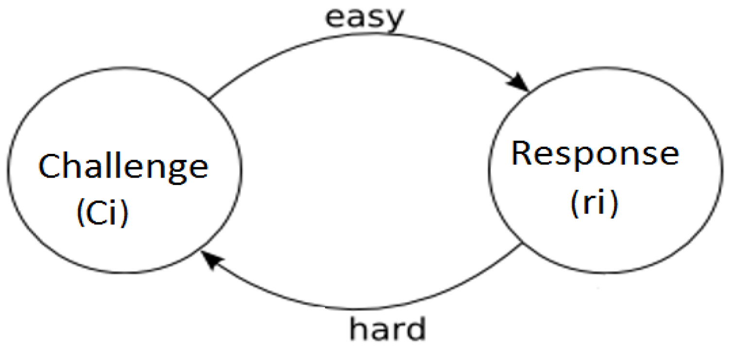
Figure 1 shows the concept of a one-way (irreversible) physical unclonable function. As seen in the figure, a silicon PUF is designed with a number of n-binary input bits, known as the input challenges. A PUF instance with the challenge-response relationship is easy to compute; however, it is very hard (almost impossible) to reverse or retrieve. For the generation of a binary response bit, an input challenge is required.
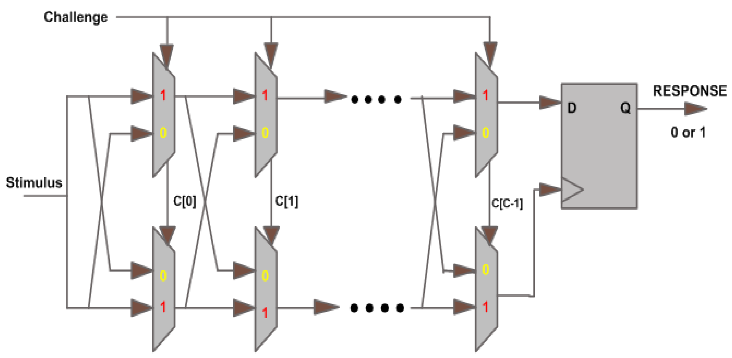
Arbiter PUFs (APUFs) are among the popular delay based PUFs. The design of an APUF circuit is presented in Figure 2 [8,10,11]. As shown in the figure, APUFs use a switch-box structure to create a race between two delay paths with an arbiter at the end. Basically, two identical delay paths are formed to produce one response bit based on the delay of these paths. For that, an arbiter (D-latch) is placed at the end of the APUF circuit to decide the winning signal that reaches first. For example, in ROPUF each input challenge is applied to select a specific pair of RO frequencies (two RO frequencies).
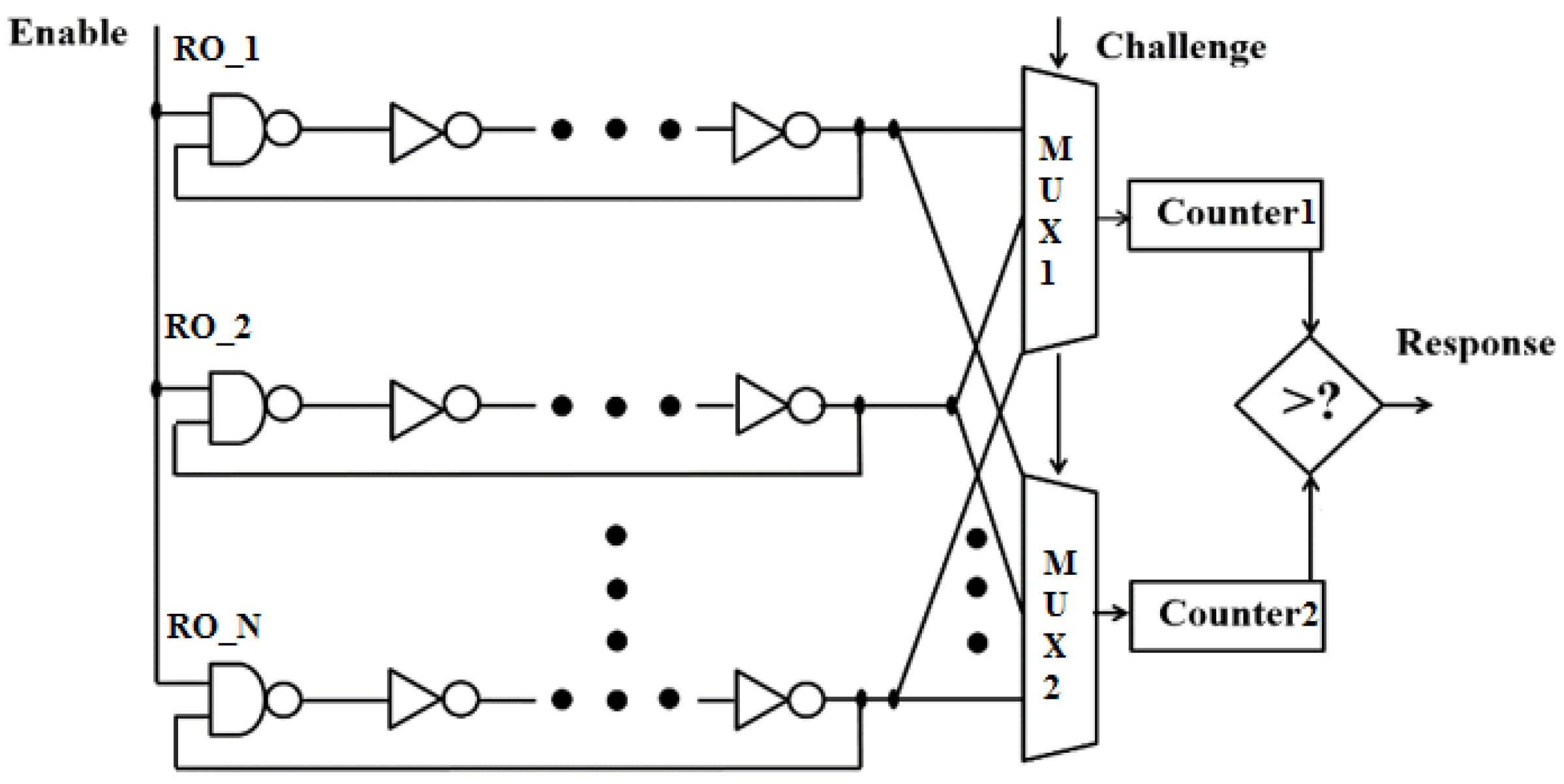
In 2002, the notion of ring oscillator PUFs (ROPUFs) has been introduced, as shown in Figure 3 [9]. As seen in the figure, ROPUF mainly consists of an odd number of serially connected inverters known as ring oscillators (ROs). The output signals of the individual ROs are fed back to their inputs to form the delay loop.
Theoretically, delay components (inverters, Muxs, routing, etc.) are assumed to be identical, as shown by different simulation software (Xilinx, Altera, NI Multisim, etc.). For example, this simulation software shows that the generated frequencies of the individual ROs are exactly the same and do not have the ability to show the real RO frequencies.
Practically, this is not the case when these frequencies are measured using physically mapped hardware designs. The inconsequential differences in ICs manufacturing process variations result in random differences in the frequencies generated by the ROs that are mapped at different locations of a silicon device. Thus, a RO generates a non-uniform clock signal (continually generates “1” and “0”) with unique frequency, leveraging manufacturing process variations of the inverters and interconnects of its delay loops. A total of n-RO comparison frequency pairs (two RO frequencies for each pair) are used to generate n-binary response bits. ROPUFs exploit these minor differences in frequencies to extract chip-unique signatures. As shown in Figure 3, the associated logic (MUXs) are used to select two ROs based on an applied challenge (Ci). There are two binary counters for counting the non-uniform number of cycles generated by each RO. These counters can be simultaneously started and stopped before hardware measurements are fed to the comparator. This circuit basically compares measured frequencies obtained from both counters to generate one response, “1” or “0”, based on a specific algorithm. Weak PUFs and strong PUFs are first introduced by Guajardo, followed by Ruhrmair et al. in [19,22,23,24,25,26]. These expressions are not meant to show that one PUF type is superior or inferior to another. For example, Arbiter PUFs (APUFs) offer a high number of CRPs, hence they are known as strong physical random functions [8]. In contrast, ring oscillator PUFs (ROPUFs) are a typical example of weak silicon PUFs, since they only offer a limited number of CRPs [3,9]. The selected RO pair is known as a challenge-response frequency pair that is used for the generation of the challenge response space or CRPs (the total number of the possible challenge responses pairs). For this, the frequencies of a selected frequency RO pair are compared for the generation of a response bit in the generated secret key. For the generation the secret key of n-binary response bits (length = n binary bits), n number of input challenges are needed. It is extremely hard (almost impossible) to fully or partially retrieve a subset of input challenges C, where is a subset of all possible set of input challenges C, given the corresponding response bits R, where is a subset of the possible set of generated responses R, as shown in Equation (1). For example, for two subsets of input challenges , the corresponding binary responses is probabilistic, can be the same or different, and cannot be used to know the applied challenges. Similarly, two silicon devices (m,n) will never generate the same signature (binary response bits) for a specific set of input challenges i.e., .
2.2. Cyber Attacks on Silicon PUFs
The entity of silicon PUFs can be accessible to an adversary who has unlimited and physical access to the device that implements a PUF design for security purposes. In such a scenario, the adversary may try to compose the PUF structure by easily retrieving a subset of the CRP space to study the behavior of the entire CRP space and model its structure. Modeling attacks that aim to clone the behavior of the CRP space of certain silicon PUFs can be driven by different Machine Learning (ML) algorithms. ML algorithms are usually used to learn the behavior of the CRP space in order to model silicon PUFs physical structure. For launching a modeling attack, ML gives a parameter based attack for modeling the PUF structures. For example, some of the standard parametric models in APUF are known as the linear additive delay models [8,19,22,23,24,25,26]. This type of modeling attack sums up the delay of an element in a certain path of an APUF to estimate the total path delay and the corresponding response bit at the end of the path. There have been other techniques used to predict the CRP space, such as solving integer equations [8] and linear programming [27]. For instance, IEEE T-IFS 2013 [22] suggests that a Slender PUF protocol is used as a resilient technique against all known machine learning attacks, and has a high performance when tested with ML algorithms
3. Proposed Dynamic Ring Oscillator Technique
Ring oscillator (RO) loops are a well-known and efficient hardware architecture for measuring FPGA/VLSI circuit delay. As explained earlier, RO loop can be simply constructed from an odd number of serially connected inverters. A ROPUF circuit is fundamentally based on ring oscillator loops, in addition to the associate hardware circuits (MUX, counters, compactor, etc.). As compared to other sPUFs, ROPUFs are easy to realize on real hardware and can provide higher performance in terms of reliability, randomness, uniqueness, etc. However, due to their weak entropy, ROPUFs may only offer a limited number of challenge-response pairs (CRP space), and, thus, they can generate smaller and fewer numbers of secret keys. For these reasons, ROPUFs are categorized as weak sPUFs, and are more vulnerable to modeling attacks [19]. Fabrication variations for the extractions of inherently unique secret keys from silicon device parameters, which interact directly with the manufacturing process variations, are at the fundamental of ROPUF research. As a drawback, prior research on the fabrication of ROPUFs has been mainly focused on the static ROPUF structure. Static ROPUFs, including the simple ROPUF design, are designed with one structure that has a limited CRP number and fixed CRP space behavior. Configurable ROPUF (c-ROPUFs) are proposed to improve the CRP space and provide better reliability [3]. Both simple and configurable ROPUFs are based on a static ROPUF structure (fixed) and generate non-updated secret keys. Dynamic ROPUFs can overcome these weaknesses by enhancing the CRP space, which allows the generation of larger and updated secret keys with dynamic behaviors.
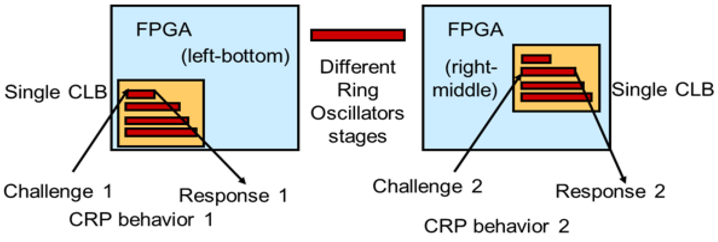
Figure 4 shows a general FPGA-based scheme for the proposed dynamic ROPUF (d-ROPUFs). As seen in the figure, the d-ROPUFs implement different RO structures (different RO stages) on different locations of silicon devices for updated CRP behaviors. For this, the d-ROPUF design should have the ability to reconfigure itself to a new structure with a different number of inverter stages that generate updated RO frequencies within new frequency ranges. The use of d-ROPUF increases CRP space and ensures for the generation of updated secret keys based on new CRP behaviors. Further, d-ROPUF can be used to randomly extract complex, large, and highly unclonable (unpredictable) cryptographic keys from different areas of silicon devices and makes it harder for an adversary to model PUF behavior or correlate input challenges to the corresponding response bits.
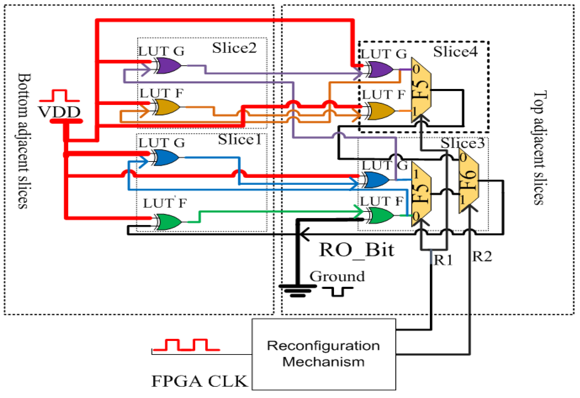
Figure 5 shows the architecture of the hardware-oriented security technique (d-ROPUF), proposed to improve ROPUFs security against new cyber attacks. The figure shows a design of dynamic, multi-stage ROPUF structures on a small area (single CLB) of and FPGA device that can be altered automatically using a configuration mechanism. As shown in the figure, the d-ROPUF design is mapped inside a single CLB of a Spartan-3E FPGA that contains eight LUTs inside four slices (two LUTs per a slice). This ensures high design efficiency in terms of low-cost, enhanced area overhead, and low power consumption of the proposed PUF when implemented on real hardware. The LUTs are programmed as an inverter or buffer-programmed XOR gates. To construct RO loops with an odd number of inverters (one, three, five, and seven inverters), seven out of the eight LUTs are configured as inverters. The eighth LUT is configured as a buffer and an extra delay to keep the generated frequency of the RO structure less than 300 MHz (less than the maximum operating frequency value of the Spartan 3E FPGA). As seen in the figure, the LUTs are connected using internal CLB routing to form four RO structures inside a single CLB. As seen in Figure 5, four d-ROPUF structures (LUTs and local routing) are distinguished in different colors. Each structure contains n LUTs with inverters and one buffer. These four RO structures are named one, three, five, and seven RO stages. As shown in the figure, the one-stage structure is implemented using the green color (two LUTs: One inverter and one buffer), the three-stage structure is implemented using green and blue colors (four LUTs: Three inverters and one buffer). The five-stage structure is implemented using green, blue, and purple colors (six LUTs: Five inverters and one buffer). Finally, the seven-stage structure is implemented using green, blue, purple, and brown colors (six LUTs: Seven inverters and one buffer). As seen in Figure 5, the enable signal (VDD), shown by the red lines, is used to activate the selected the CLB and configure the PXOR LUTs to buffer/inverter. The creation of identical ring oscillator loops is important to eliminate the delay caused by the dynamic routing of FPGA devices.
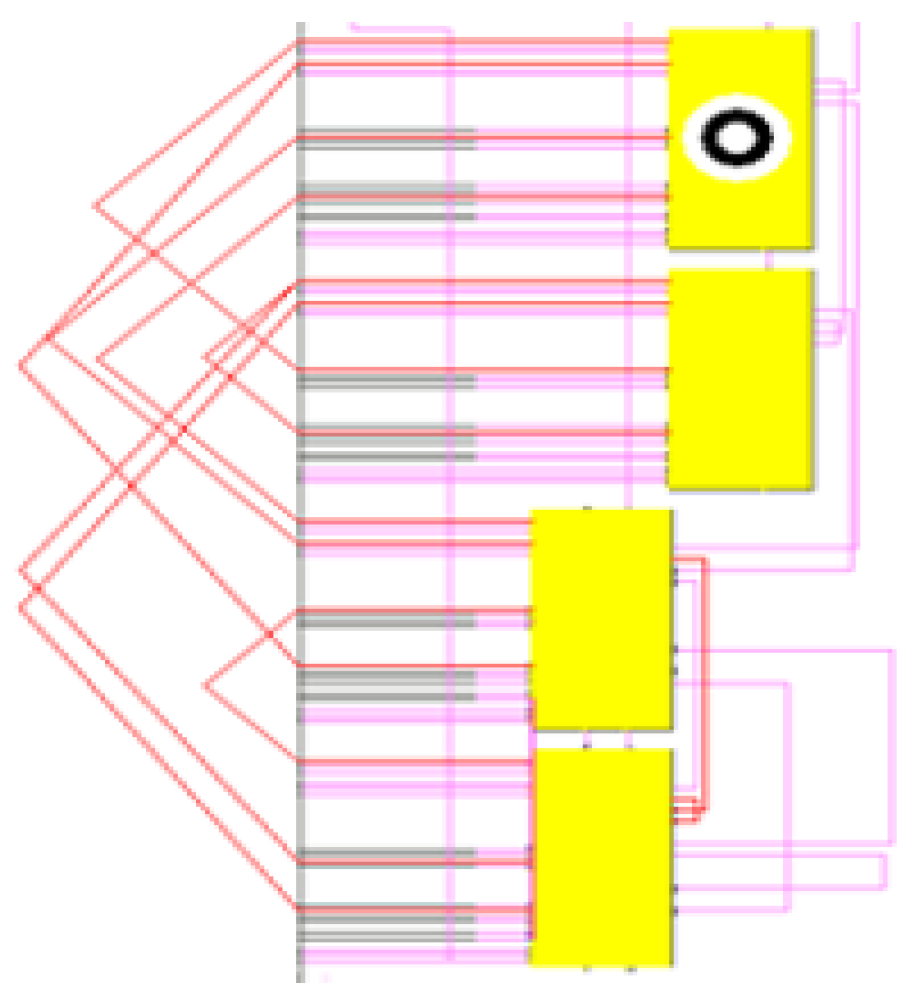
Figure 6 shows the implementation of a hard macro for the proposed design in a single CLB (four slices) of the Spartan-3E FPGA. A hard macro design is a necessary procedure to comply with the creation of identical RO loops and routing requirements.
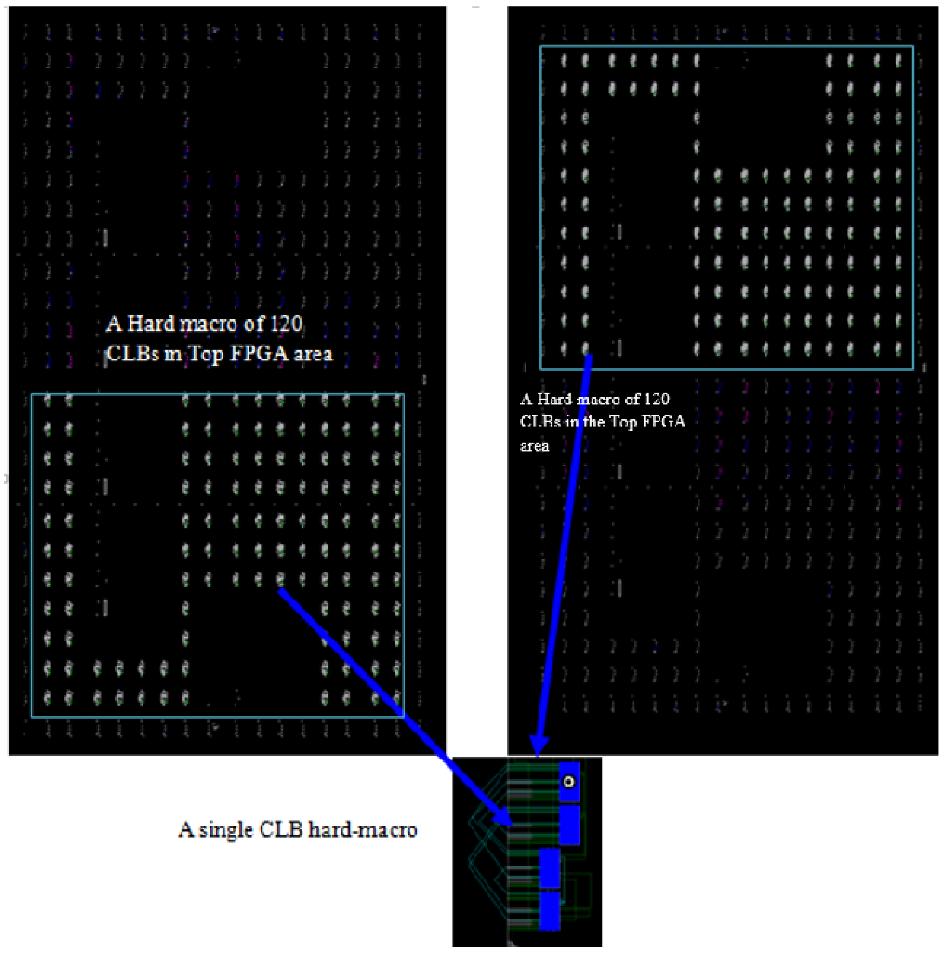
Figure 7 shows the implementation of the d-ROPUF design on top and bottom FPGA regions. As seen in the figure, the created hard macro design is instantiated on the top and bottom 120 CLBs for mapping the design onto the entire area of the FPGAs.
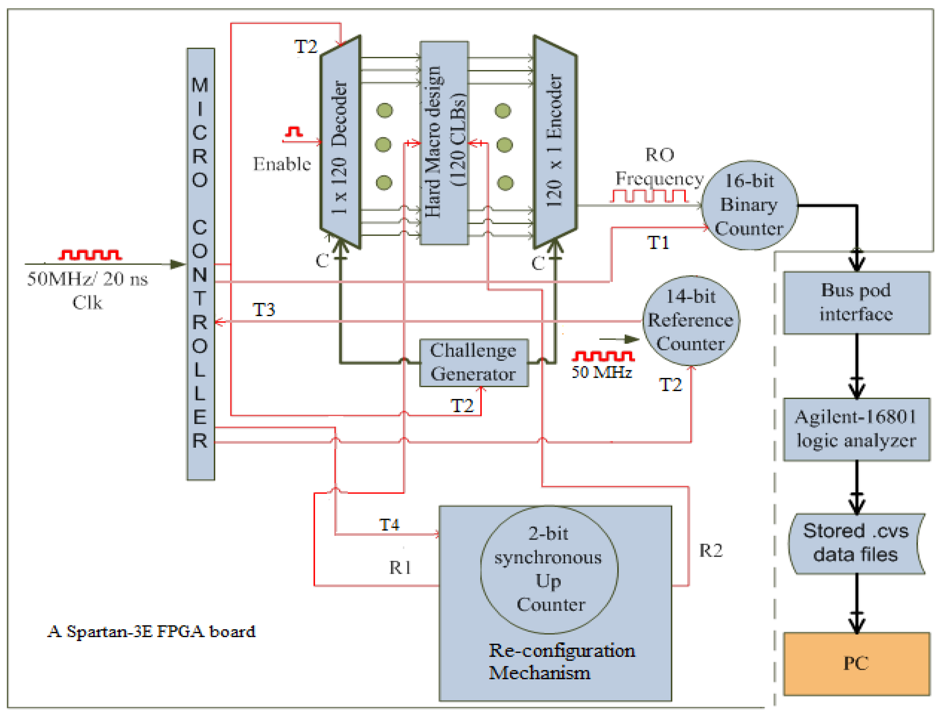
To implement the design on the entire area of FPGA, each FPGA area is divided into top and bottom regions with 120 CLBs for each region. The hard macro design is instantiated at all the CLBs in each FPGA area separately. Figure 8 shows the full architecture of the proposed d-ROPU technique for an FPGA area with 120 CLBs.The figure shows a timing micro-controller that controls activation and deactivation periods, challenge generator, 120 decoders and encoder, hard macro of the individual ROs, the reconfiguration mechanism, and main and reference counters connected to a logic analyzer and PC for the collection of data samples. A short delay period (stabilization period) is needed prior to the activation of the main counter for the signal to be stabilized before the counter starts to measure the actual frequency of the activated RO.
As shown in Figure 8, as soon as the T1 signal is received by the 16-bit binary counter, the counter starts counting for a stabilization period of 0.1 ms (prior to the activation of any RO). At the end of the stabilization period, a T2 is sent to the challenge generator, 120 decoders, and a 14-bit reference counter for the activation of a selected RO. The main counter counts the number of clock cycles of the active RO for 0.1 ms (activation period). At the same period, the reference counter counts the number of clock cycles of the reference clock (50 MHz) with a step size of 5000 clock cycles. At the end of the activation period, the timing controller receives a T3 signal from the reference counter to send a deactivation signal to deactivate the running RO and stop the counters. As soon as the deactivation T2 signal is received, the decoder disconnects the active RO and the challenge generator automatically generates the proper challenge for the next RO to be activated, and the reference counter zeros out its values and stops the counting process. When the deactivation T1 signal is received, the main counter stops the counting process and forwards the counted number of clock cycles to the Agilent logic analyzer through a 16-bit data bus connection. To avoid the self-heating noise of the neighboring ROs, each RO is activated for a shorter time of 0.1 ms (activation period), and another period of 0.1 ms is allowed before the activation of the next RO. Since a total of 10 sample frequencies per an individual RO is considered for data analysis, the total time of the 10 RO runs in a d-ROPUF structure is ms = 0.003 s. For the collection of the data samples from a d-ROPUF structure (120 ROs), a total time of 120 ROs × 0.003 ms = 0.36 s is needed.
As shown in Figure 8, upon receiving T4 by the re-reconfiguration mechanism (after every 0.36 s), R1 and R2 signals are automatically generated to reconfigure the d-ROPUF design to a new structure with a different number of RO stages. These signals are separately generated (a part of the input challenge) and properly controlled by the reconfiguration mechanism and the timing controller. This iterative process is continued, and the generated RO sample frequencies for the d-ROPUF structures are collected in the form of data sheets and stored at the logic analyzer before they are analyzed using a PC.
4. Experimental Results and Discussions
4.1. Reliability and Bit Flips
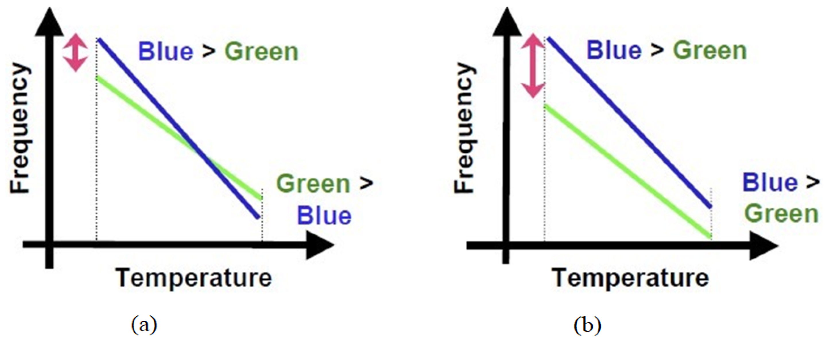
Figure 9a,b shows the concept behind bit flip occurrence in the PUF output at varying temperatures due to the change in the RO frequencies [9]. As seen in the figures, as the temperature increases, the frequencies represented in blue and green lines (two RO frequencies of a selected frequency pair) decreases. As shown in Figure 9a, as the temperature increases, the blue line drops faster than the green one, which makes its frequency value less than the value of green line (below RO frequency < green RO frequency).
This results in a bit flip occurrence in the generated PUF output at different temperatures. However, as illustrated in Figure 9b, even if the temperature increases, the blue line did not drop faster than the green line, and thus, there is no bit flip occurrence in this case. From the same figures, it is observed that the value of frequency difference between the blue RO frequency and green RO frequency lines in Figure 9a is smaller as compared to the same value in Figure 9b. For the selection of reliable RO frequency pairs, a higher value of the frequency difference plays the key role in preventing bit flips in the generate PUF responses. In other words, bit flips can be prevented by selecting the RO frequency pairs with reliable frequency differences.
4.2. Optimal Time Delay Algorithm (OTDA)
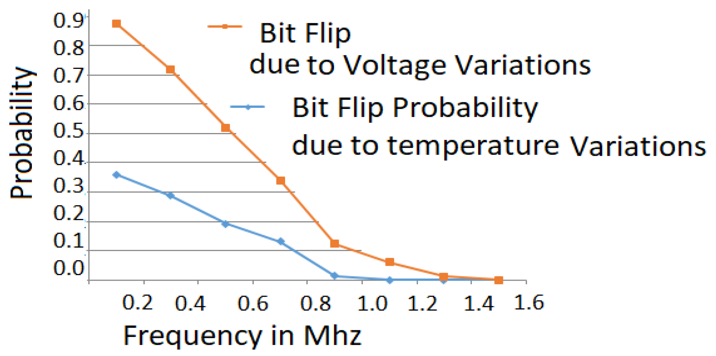
The proposed OTDA is an executive comparison based algorithm that compares sample frequencies based on their O() complexity. Figure 10 shows the results of the experimental study to determine reliable frequency difference threshold used to prevent bit flip occurrences [6]. This threshold is used to generate a reliable PUF output at varying operating conditions using data samples collected from a population of 30 Spartan 3E FPGAs. From the figure, it is observed that RO frequency pairs with frequency differences of 1.5 MHz or higher can be considered reliable in avoiding bit flip occurrences. This value (1.5 MHz) is the reliable threshold where the probability of a bit flip in the generated response bits is 0%. The OTDA is divided into two main steps. The generation of reliable CRPs of different d-ROPUF structures is step 1, which is represented by Algorithm 1 [6].
| Algorithm 1 OTD algorithm step1: Reliable CRPs generation |
| procedure Generation() ▹ (number of RO frequencies of each d-ROPUF structure) ▹ (i, j are loop counters for the location of reliable RO frequency pairs) ▹ (k is row counter (k rows) of reliable challenge-response array CRPs[k,5]) ▹ (Initialize RO Time delays) ▹ (Assign the reliable threshold value) ▹ (Store RO frequencies of d-ROPUF in an f array) while do while do if () then if ( then else end if end if end while end while end procedure |
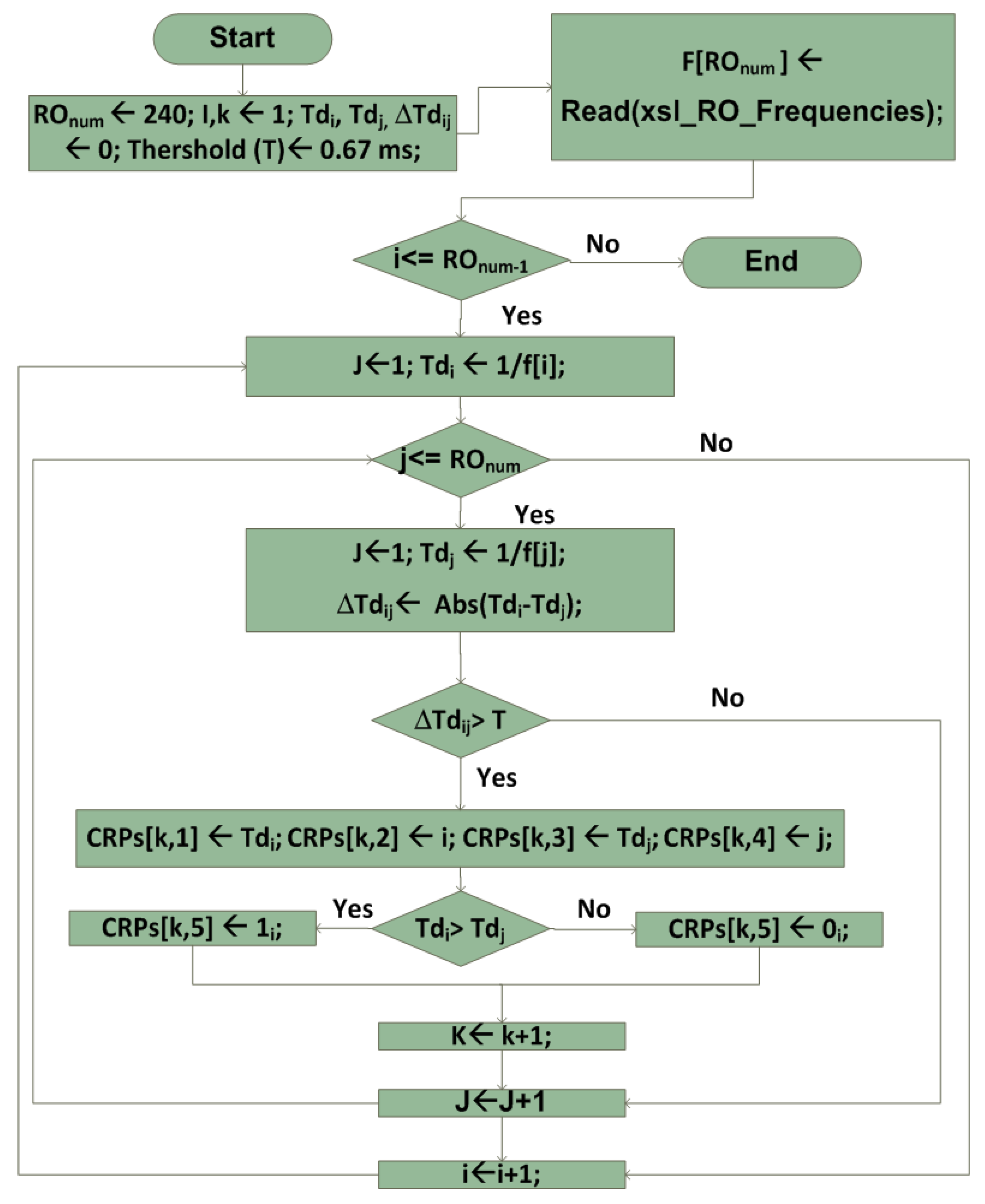
The OTDA step 1 flowchart is also shown in Figure 11. As seen in the figure, sample frequencies of the individual ROs that are generated at certain operating conditions (temperature and/or supply voltage) are the main input data to the OTDA. The goal of this step is to store reliable frequency pairs with a frequency difference of 1.5 MHz or higher.
To accomplish this, an RO frequency freq(i) is compared with all RO frequencies, an operation having complexity, using time delays (, ) of RO frequency pairs. These time delays are computed as follows:
The absolute difference between the time delays () is computed and used to generate reliable responses as follows:
The reliable threshold (R.T.) value is empirically calculated from data samples (RO frequencies) that are collected under varying operating conditions. A reliable response bit is generated based on the following equations:
The input and output of the OTDA are as follows:
- Inputs: 240 frequencies extracted for one, three, five, and seven stages of d-ROPUF structures represented as .
- Output: List of the possible reliable RO frequency pairs stored in an array, named CRPs(n:5), in n rows and five columns, where .
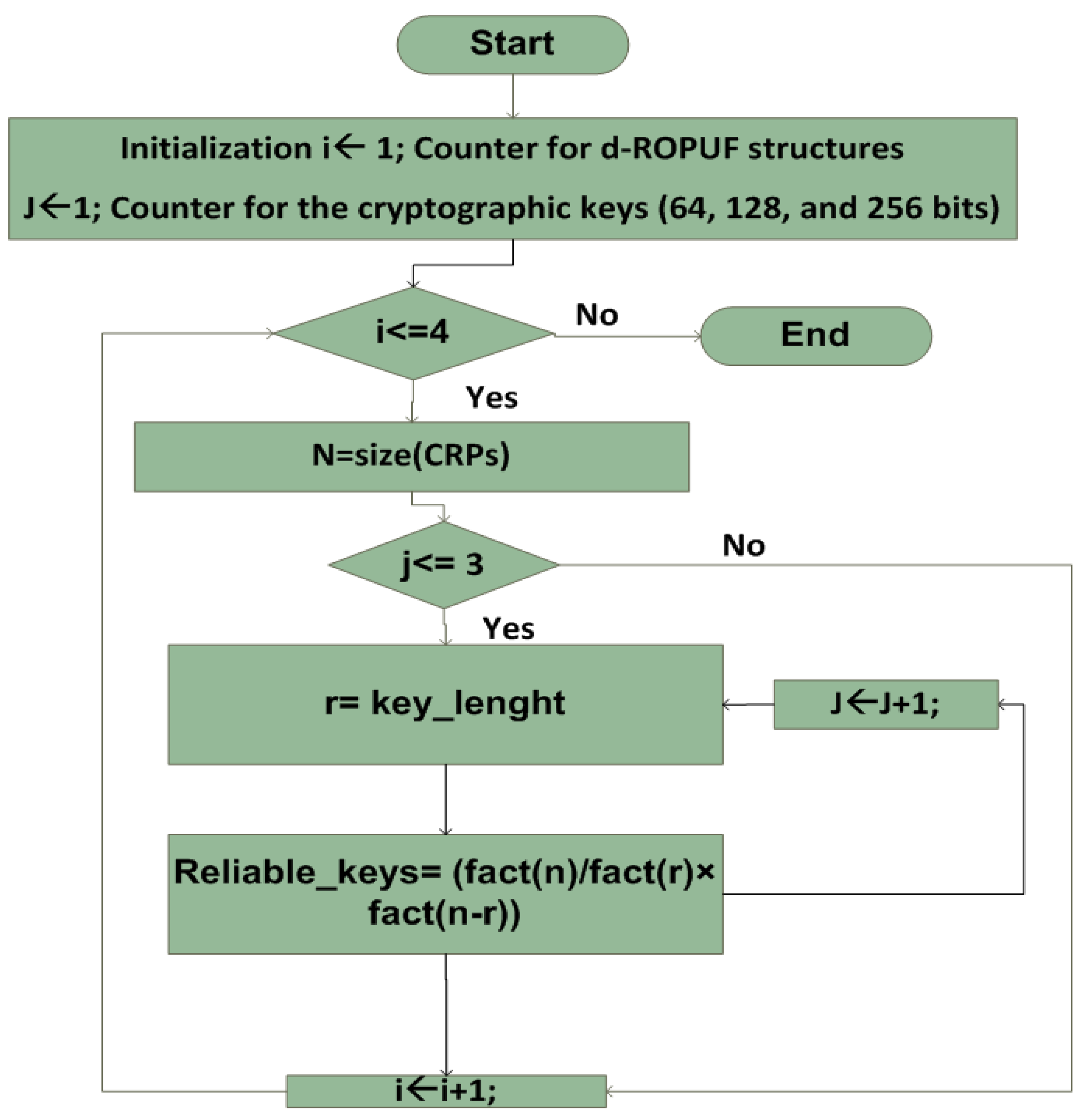
Specifically, the first two values of each row of are the frequency pairs (f(i), f(j)) of the reliable ROi and ROj (that passes the optimal time delay threshold). The next two values are the indexes of these ROs (i and j values). The last value is the reliable response bit r (0 or 1) generated by comparing the frequencies of the two ROs. As previously mentioned, the OTD algorithjm aims to enhance the capability of the d-ROPUF to obtain larger a CRP space, computed using the probability of combinations of statistical formula as shown in Figure 12. For this, sample RO frequencies are digitized using the proposed OTD algorithm and the neighbor coding algorithm, as used by previous researchers [3,9]. Response bits are generated from the top and bottom (120 CLBs) of 30 FPGAs, and the possible number of reliable bits are obtained with the help of the OTDA algorithm. After the selection of reliable response bits from different d-ROPUF structures, Algorithm 1 is used to determine the possible cryptographic keys of length 64, 128, and 256 as follows:
- Inputs: CRP[i,j] the set of the reliable response bits for 1, 3, 5, 7 stages of ROs that is the result of Algorithm 1.
- Output: The list of all possible m reliable cryptographic keys (64, 128, 256).
The number of possible reliable RO comparison Challenge Response Pairs (CRPs) for all d-ROPUF stages (one, three, five, seven), that pass the reliability threshold (OTD > 0.67 ms) for 30 different FPGA chips (S3E100) are shown in Table 1. Table 1 shows the number of reliable d-ROPUF response bits generated at varying temperatures. The table also shows the result of all possible reliable RO comparison CRPs for d-ROPUFs (three stages) which pass the optimal time delay threshold (OTD > 0.67 ms) for 30 FPGAs.
It is observed that the OTDA can enhance the capability of the CRP space based on the probability of combinations of statistical formula. Table 1 shows a substantial improvement in the possibly reliable cryptographic keys of different lengths (64 bits, 128 bits, 256 bits, and 512 bits) which highly improves the security of the ROPUF against modeling attacks.
5. Conclusions
This paper presents a dynamic ROPUF structure (d-ROPUF) with updated challenge/response behavior to boost silicon PUF’s security against modeling and machine learning attacks. The design is implemented and evaluated on 30 Spartan 3E FPGA devices under varying operating conditions. An Optimal Time Delay Algorithm (ODTA) is proposed to improve the reliability and improve the CRP space of silicon PUFs. Experimental results show that the proposed algorithm generates a considerable number of reliable comparison pairs with no bit-flips occurrence at varying environmental conditions.
Author Contributions
Formal analysis, F.A.; Investigation, A.D.; Validation, M.N.; Writing—review and editing, S.K.
Funding
This research received no external funding.
Conflicts of Interest
The authors declare no conflict of interest.
References
- Maiti, A.; Schaumont, P. Improving the quality of physical unclonable function using configurable ring oscillators. In Proceedings of the 2009 International Conference on Field Programmable Logic and Applications, Prague, Czech Republic, 31 August–2 September 2009. [Google Scholar]
- Xin, X.; Jens, P.; Kris, K. A Configurable RO-Based PUF for Xilinx FPGAs. In Proceedings of the 14th Euromicro Conference on Digital System Design, Oulu, Finland, 31 August–2 September 2011. [Google Scholar]
- Amsaad, F.; Hoque, T.; Niamat, M. Analyzing the performance of a configurable ROPUF design controlled by programmable XOR gates. In Proceedings of the IEEE 58th International Midwest Symposium on Circuits and Systems, Fort Collins, CO, USA, 2–5 August 2015. [Google Scholar]
- Kursawe, K.; Sadeghi, A.; Schellekens, D.; Skoric, B.; Tuyls, P. Re-configurable physical unclonable functions-enabling technology for tamper-resistant storage. In Proceedings of the 2009 IEEE International Workshop on Hardware-Oriented Security and Trust (HOST), Francisco, CA, USA, 27 July 2009. [Google Scholar]
- Mustapa, M.; Alam, M.; Killian, T.; Niamat, M. Frequency uniqueness in ring oscillator Physical Unclonable Functions on FPGAs. In Proceedings of the 2013 IEEE 56th International Midwest Symposium on Circuits and Systems (MWSCAS), Columbus, OH, USA, 4–7 August 2013. [Google Scholar]
- Amsaad, F.; Choudhury, M.; Chaudhuri, C.; Niamat, M. An innovative delay-based algorithm to boost PUF security against machine learning attacks. In Proceedings of the Annual IEEE Connecticut Conference on Industrial Electronics, Technology and Automation (CT-IETA), Bridgeport, CT, USA, 14–15 October 2016. [Google Scholar]
- Amsaad, F.; Pundir, N.; Niamat, M. A Dynamic Area-Efficient Technique to Enhance ROPUFs Security Against Modeling Attacks. In Computer and Network Security Essentials; Springer: Cham, Switzerland, 2018; pp. 407–425. [Google Scholar]
- Lim, D.; Lee, J.W.; Gassend, B. Extracting secret keys from integrated circuits. IEEE Trans. Very Large Scale Integr. Syst. 2005, 13, 1200–1205. [Google Scholar]
- Edward Suh, G.; Devadas, S. Physical unclonable functions for device authentication and secret key generation. In Proceedings of the 2007 44th ACM/IEEE Design Automation Conference, San Diego, CA, USA, 4–8 June 2007. [Google Scholar]
- Pundir, N.; Hazari, N.; Amsaad, F.; Niamat, M. A novel hybrid delay based physical unclonable function immune to machine learning attacks. In Proceedings of the 2017 IEEE National Aerospace and Electronics Conference (NAECON), Dayton, OH, USA, 27–30 June 2017. [Google Scholar]
- Pundir, N.; Amsaad, F.; Choudhury, M.; Niamat, M. Novel technique to improve the strength of weak arbiter PUF. In Proceedings of the 2017 IEEE 60th International Midwest Symposium on Circuits and Systems (MWSCAS), Boston, MA, USA, 6–9 August 2017. [Google Scholar]
- Helfmeier, C.; Boit, C.; Nedospasov, D.; Seifert, J. Cloning Physically Unclonable Functions. In Proceedings of the 2013 IEEE International Symposium on Hardware-Oriented Security and Trust (HOST), Austin, TX, USA, 2–3 June 2013. [Google Scholar]
- Nedospasov, D.; Seifert, J.; Helfmeier, C.; Boit, C. Invasive PUF Analysis. In Proceedings of the 2013 Workshop on Fault Diagnosis and Tolerance in Cryptography, Santa Barbara, CA, USA, 20 August 2013. [Google Scholar]
- Merli, D.; Schuster, D.; Stumpf, F.; Sigl, G. Semi-invasive EM attack on FPGA RO PUFs and countermeasures. In Proceedings of the Workshop on Embedded Systems Security, Taipei, Taiwan, 9–14 October 2011. [Google Scholar]
- Azhar, M.; Amsaad, F.; Köse, S. Duty-Cycle-Based Controlled Physical Unclonable Function. IEEE Trans. Very Large Scale Integr. Syst. 2018. [Google Scholar] [CrossRef]
- Deb Nath, A.; Amsaad, F.; Choudhury, M.; Niamat, M. Hardware-based novel authentication scheme for advanced metering infrastructure. In Proceedings of the 2016 IEEE National Aerospace and Electronics Conference (NAECON) and Ohio Innovation Summit (OIS), Dayton, OH, USA, 25–29 July 2016. [Google Scholar]
- Amsaad, F.; Chaudhuri, C.; Deb Nath, A.; Niamat, M. A novel security technique to generate truly random and highly reliable reconfigurable ROPUF-based cryptographic keys. In Proceedings of the 2016 IEEE International Symposium on Hardware-Oriented Security and Trust (HOST), McLean, VA, USA, 3–5 May 2016. [Google Scholar]
- Hoque, T.; Mustapa, M.; Amsaad, F.; Niamat, M. Assessment of NAND based ring oscillator for hardware Trojan detection. In Proceedings of the 2015 IEEE 58th International Midwest Symposium on Circuits and Systems (MWSCAS), Fort Collins, CO, USA, 2–5 August 2015. [Google Scholar]
- Herder, C.; Koushanfar, F.; Devadas, S. Physical Unclonable Functions and Applications: A Tutorial. Proc. IEEE 2014, 102, 1126–1141. [Google Scholar] [CrossRef]
- Amsaad, F.; Chaudhuri, C.; Niamat, M. Reliable and reproducible PUF based cryptographic keys under varying environmental conditions. In Proceedings of the 2016 IEEE National Aerospace and Electronics Conference (NAECON) and Ohio Innovation Summit (OIS), Dayton, OH, USA, 25–29 July 2016. [Google Scholar]
- Chaudhuri, C.; Amsaad, F.; Niamat, M. Impact of temporal variations on the performance and reliability of configurable ring oscillator PUF. In Proceedings of the 2016 IEEE National Aerospace and Electronics Conference (NAECON) and Ohio Innovation Summit (OIS), Dayton, OH, USA, 25–29 July 2016. [Google Scholar]
- Rührmair, U.; Sölter, J.; Sehnke, F. PUF Modeling Attacks on Simulated and Silicon Data. IEEE Trans. Inf. Forensics Secur. 2013, 8, 1876–1891. [Google Scholar] [CrossRef] [Green Version]
- Ye, J.; Guo, Q.; Hu, Y.; Li, H.; Li, X. Modeling Attacks on Physical Unclonable Functions. In Proceedings of the 2018 IEEE 36th VLSI Test Symposium (VTS), San Francisco, CA, USA, 22–25 April 2018. [Google Scholar]
- Delvaux, J.; Verbauwhede, I. Side channel modeling attacks on 65nm arbiter PUFs exploiting CMOS device noise. In Proceedings of the 2013 IEEE International Symposium on Hardware-Oriented Security and Trust (HOST), Austin, TX, USA, 2–3 June 2013. [Google Scholar]
- Kumar, S.; Guajardo, J.; Maes, R.; Schrijen, G.; Tuyls, P. FPGA intrinsic PUFs and their use for IP protection. In Proceedings of the 2008 IEEE International Workshop on Hardware-Oriented Security and Trust, Anaheim, CA, USA, 9 June 2008. [Google Scholar]
- Rostami, M.; Wendt, J.; Potkonjak, M.; Koushanfar, F. Security based on Physical Unclonability and Disorder. In Proceedings of the 2014 Design, Automation and Test in Europe Conference and Exhibition, Dresden, Germany, 24–28 March 2014. [Google Scholar]
- Öztürk, E.; Hammouri, G.; Sunar, B. Towards robust low-cost authentication for pervasive devices. In Proceedings of the 2008 Sixth Annual IEEE International Conference on Pervasive Computing and Communications (PerCom), Hong Kong, China, 17–21 March 2008. [Google Scholar]
Figure 1.
Physical unclonable function concept.

Figure 2.
Arbiter PUF (APUF) circuity.

Figure 3.
Ring oscillator PUF (ROPUF) circuity.

Figure 4.
General FPGA-based dynamic ROPUF scheme.

Figure 5.
Proposed FPGA-based d-ROPUF scheme of a single CLB.

Figure 6.
Implementation of a hard macro design of a single CLB.

Figure 7.
Implementation of the proposed d-ROPUF technique for an FPGA area (120 CLBs).

Figure 8.
A complete circuit design of the proposed d-ROPUF technique for an FPGA area (120 CLBs).

Figure 9.
A complete circuit design of the proposed d-ROPUF technique for an FPGA area (120 CLBs).

Figure 10.
Reliable frequency difference threshold.

Figure 11.
OTD algorithm step1: Reliable CRPs generation flowchart.

Figure 12.
OTD algorithm flowchart: Step 2.


Table 1.
Reliable d-ROPUF response bits generated at varying temperatures.
| FPGA | Reliable Response | 64-Bits | 128-Bits | 256-Bits | 512-Bits |
|---|---|---|---|---|---|
| 1 | 828 | 3.67 × 10 | 2.63× 10 | 5.40× 10 | 3.44× 10 |
| 2 | 834 | 5.93× 10 | 7.18× 10 | 1.61× 10 | 1.07× 10 |
| 3 | 834 | 5.93× 10 | 7.18× 10 | 3.20× 10 | 1.07× 10 |
| 4 | 870 | 9.13× 10 | 2.14× 10 | 5.93× 10 | 9.97× 10 |
| 5 | 804 | 4.76× 10 | 3.70× 10 | 5.22× 10 | 6.51× 10 |
| 6 | 851 | 2.10× 10 | 1.00× 10 | 1.45× 10 | 3.40× 10 |
| 7 | 827 | 3.38× 10 | 2.22× 10 | 1.85× 10 | 1.31× 10 |
| 8 | 877 | 1.55× 10 | 6.51× 10 | 3.75× 10 | 4.82× 10 |
| 9 | 834 | 5.48× 10 | 6.08× 10 | 2.70× 10 | 4.10× 10 |
| 10 | 840 | 9.56× 10 | 1.94× 10 | 1.89× 10 | 3.10× 10 |
| 11 | 888 | 3.84× 10 | 4.26× 10 | 1.77× 10 | 1.60× 10 |
| 12 | 896 | 6.96× 10 | 1.47× 10 | 1.33× 10 | 1.47× 10 |
| 13 | 825 | 2.66× 10 | 1.34× 10 | 1.77× 10 | 7.22× 10 |
| 14 | 883 | 2.64× 10 | 1.95× 10 | 1.85× 10 | 2.15× 10 |
| 15 | 824 | 2.45× 10 | 1.13× 10 | 5.13× 10 | 2.73× 10 |
| 16 | 874 | 1.23× 10 | 4.05× 10 | 1.76× 10 | 3.44× 10 |
| 17 | 816 | 1.28× 10 | 2.92× 10 | 4.86× 10 | 1.07× 10 |
| 18 | 800 | 3.71× 10 | 2.19× 10 | 8.57× 10 | 3.08× 10 |
| 19 | 813 | 1.08× 10 | 2.07× 10 | 2.90× 10 | 1.48× 10 |
| 20 | 896 | 6.47× 10 | 1.26× 10 | 5.96× 10 | 6.32× 10 |
| 21 | 831 | 4.67× 10 | 4.35× 10 | 8.93× 10 | 6.12× 10 |
| 22 | 850 | 2.10× 10 | 1.00× 10 | 9.16× 10 | 3.40× 10 |
| 23 | 845 | 1.31× 10 | 3.75× 10 | 9.56× 10 | 1.30× 10 |
| 24 | 887 | 3.56× 10 | 3.65× 10 | 5.99× 10 | 6.81× 10 |
| 25 | 893 | 5.17× 10 | 7.94× 10 | 1.53× 10 | 4.93× 10 |
| 26 | 820 | 1.92× 10 | 6.83× 10 | 8.57× 10 | 1.46× 10 |
| 27 | 852 | 2.45× 10 | 1.39× 10 | 1.45× 10 | 2.14× 10 |
| 28 | 869 | 8.42× 10 | 1.82× 10 | 6.30× 10 | 4.09× 10 |
| 29 | 844 | 1.31× 10 | 3.75× 10 | 5.78× 10 | 1.31× 10 |
| 30 | 888 | 3.56× 10 | 3.65× 10 | 8.67× 10 | 6.81× 10 |
© 2018 by the authors. Licensee MDPI, Basel, Switzerland. This article is an open access article distributed under the terms and conditions of the Creative Commons Attribution (CC BY) license (http://creativecommons.org/licenses/by/4.0/).
Share and Cite
MDPI and ACS Style
Amsaad, F.; Niamat, M.; Dawoud, A.; Kose, S. Reliable Delay Based Algorithm to Boost PUF Security Against Modeling Attacks. Information 2018, 9, 224. https://0-doi-org.brum.beds.ac.uk/10.3390/info9090224
AMA Style
Amsaad F, Niamat M, Dawoud A, Kose S. Reliable Delay Based Algorithm to Boost PUF Security Against Modeling Attacks. Information. 2018; 9(9):224. https://0-doi-org.brum.beds.ac.uk/10.3390/info9090224
Chicago/Turabian StyleAmsaad, Fathi, Mohammed Niamat, Amer Dawoud, and Selcuk Kose. 2018. "Reliable Delay Based Algorithm to Boost PUF Security Against Modeling Attacks" Information 9, no. 9: 224. https://0-doi-org.brum.beds.ac.uk/10.3390/info9090224
Note that from the first issue of 2016, this journal uses article numbers instead of page numbers. See further details here.