1. Introduction
The most common austenitic stainless steel (SS) used for manufacturing osteosynthesis devices is 316L [
1], although applications are confined to temporary bone healing, such as screws and fixations [
2], due to sensitivity to crevice corrosion. Prolonged contact with body fluids increases the likelihood of 316L SS localized corrosion [
3], thus promoting the release of metallic ions into the adjacent tissues and the degradation of the implant. In this regard, the release of nickel (Ni) in concentrations exceeding the admissible level causes allergy, carcinogenicity, cytotoxicity and genotoxicity [
3]. As per the in-use mechanical behavior, 316L SS exhibits inadequate fatigue resistance in several orthopedic devices subjected to exceptionally high stresses, such as Harrington rods for treating scoliosis and sliding-compression plate-screw systems used in fracture fixation procedures [
4]. Consequently, numerous experimental studies in the literature have focused on providing an alternative to the austenitic SS employed in the biomedical field, using duplex stainless steels (DSS). DSS shows a double-phase structure containing approximately equal amounts of austenite (γ-Fe) and ferrite (α-Fe), resulting in a suitable combination of mechanical properties and resistance to corrosion [
5].
Cigada et al. [
6] found higher fatigue limits of the 25Cr-7Ni-4Mo-0.28N DSS (2507 alloy) relative to the 18Cr-14Ni-2.5Mo austenitic SS (ASTM F138), investigated in the same cold-worked conditions. Furthermore, Gregorutti et al. [
3] compared the mechanical response of the 2507 DSS to the 18Cr-12.5Ni-2.5Mo austenitic SS (ASTM F745), showing that the yield strength (YS) and ultimate tensile strength (UTS) of tensile tested samples processed by investment casting are almost twice as large in DSS [
3]. Such enhancement of mechanical strength in DSS was attributed to the smaller grain size typical of DSS and to solid solution hardening, promoted by the higher content of substitutional Cr and Mo atoms as well as of interstitial N atoms [
3]. Moreover, elongation tests carried out under the same conditions provided 20% for DSS and up to 30% for the austenitic SS. The higher ductility of the SS was attributed to its fully austenitic structure, while the presence of ferrite, in addition to austenite in DSS, reduces ductility and increases mechanical strength [
3].
The in vitro corrosion behavior of DSS has been deeply investigated in the literature by degradation tests in different artificial physiological solutions, resulting in lower susceptibility to localized corrosion relative to austenitic SS [
3,
4,
6,
7,
8,
9,
10,
11]. Several studies also focused on the improvement of surface corrosion behavior following surface treatment with electrical discharge machining (EDM) [
7] and the coating of a hydroxyapatite (Hap) and hydroxyapatite/titania (Hap/TiO
2) nanocomposite [
5] using an electrophoretic deposition (EPD) process [
12].
In vivo investigations were conducted on sheep and rabbits to assess the biocompatibility and the in vivo localized corrosion resistance of cold-worked 2507 DSS, compared to AISI 304L and ASTM F138 austenitic SS [
6]. After implant, examination of femur sections from rabbits and sheep demonstrated a bone formation in proximity to the metal implants, devoid of any intervening connective tissue. However, the results of corrosion tests indicated the occurrence of pitting corrosion on the AISI 304L, crevice corrosion on the ASTM F138, while no evidence of corrosion was observed on the 2507 DSS [
6]. Based on the in vivo results obtained, a preliminary clinical investigation was carried out on patients by the implantation of two or more Ender-type endomedullary nails in 2507 DSS and ASTM F138, inserted in the femoral neck for six months [
6]. A significant portion of Ender nails produced in ASTM F138 showed severe crevice corrosion, which originated from the interface region between the nails. By contrast, the application of 2507 DSS resulted in minor fretting and the absence of crevice corrosion [
6]. Moreover, Cigada et al. [
13] developed a device consisting of two metallic disks sandwiched between two PTFE disks, for evaluating the in vivo resistance to localized corrosion of ASTM F138 and 2507 DSS. This anti-corrosion device was surgically inserted into the trochanteric region of the femurs of rabbits. After 12 months of device implant, the occurrence of pitting corrosion was noticed on the AISI 304 austenitic SS. Additionally, crevice corrosion was detected on the ASTM F138 austenitic SS; however, no signs of corrosion were observed on the 2507 DSS. The main corrosion occurred at the interface between metal and PTFE [
13]. Therefore, in vivo results in the literature indicate that the 2507 DSS is not susceptible to crevice corrosion within the human body, at least under static conditions, and can be considered a good biocompatible material.
Thence, DSS is a viable alternative to austenitic stainless steels for bone tissue engineering applications, due to its crevice resistance in chloride media, high mechanical strength and biocompatibility [
3]. However, DSS use in the biomedical field must still be validated, mainly due to the limited understanding of DSS behavior when exposed to magnetic fields in terms of device heating or movement that can be injurious to the human body [
3].
In bone tissue regeneration, a focal point for scaffold fabrication is elementary unit cell geometry, which influences the mechanical and biological performances of the designed structure [
14]. Functional grading of unit cells is a promising approach in addressing the biomechanical requirements of bone, since it allows to program the deformation behavior of the scaffold by controlling the local relative density of unit cells. Thus, graded reticular structures enable the design of implants with local stiffness matching that of the target bone [
15].
Additive manufacturing (AM) exhibited remarkable advantages for the fabrication of metal parts of customized geometry, and laser powder bed fusion (LPBF) technology has been widely investigated to produce DSS. Fine control of the LPBF processing parameters enables a comprehensive analysis of the DSS microstructural evolution as well as formation quality, which are critical points for designing the performance of biomedical devices, including mechanical properties and resistance to corrosion. Nevertheless, phenomena involved in the LPBF production process, such as laser-powder interaction drawbacks and extremely high solidification rates, make the fabrication of devices with high surface quality and a predictable microstructure still quite challenging [
16].
To date, there is a lack of studies focused on the behavior of DSS fabricated by AM for tissue engineering applications. Furthermore, no studies have addressed the production of DSS scaffolds for tissue engineering applications with graded lattice geometries, although graded structures have been shown to be suitable for enhancing tissue ingrowth and for tailoring the biomechanical response of scaffolds [
17,
18,
19]. In a previous paper we reported on the structural, mechanical and biological performances of additively manufactured graded scaffolds based on the 316L austenitic stainless steel in order to investigate their biomechanical response in perspective of bone tissue regeneration [
15]. Taking as a reference the results obtained on the 316L scaffolds [
15], in this paper we report on the biomechanical response of additively manufactured graded scaffolds based on the F53 DSS. The aim of this experimental work is to investigate the biomechanical properties of DSS graded scaffolds produced by LPBF and compare such properties to the in vitro behavior of the 316L scaffolds studied in our previous work [
15]. Following the results of our previous work on S316L [
15], dense-out (DO) graded geometry based on the rhombic dodecahedral (RD) elementary unit cell was adopted here for the manufacturing of the DSS scaffolds. After production, the DSS scaffolds were submitted to microstructural, mechanical and biological characterization, and their biomechanical response was compared to the behavior of the S316L scaffolds produced and investigated under similar conditions in a previous paper [
15].
2. Materials and Methods
2.1. Scaffold Design
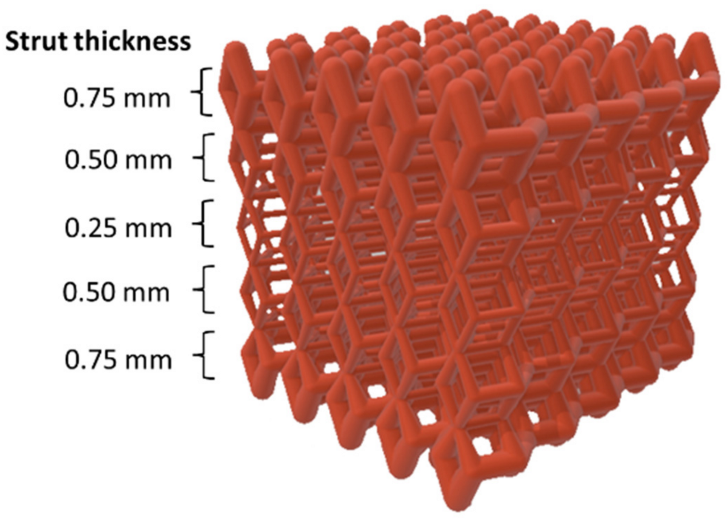
The same dense-out (DO) graded lattice geometry adopted in our previous work on 316L SS [
15] was used in this experimental work (
Figure 1). Cubic scaffolds with 10 mm sides with a total scaffold volume Vs. = 1000 mm
3 were obtained by repeating in space a rhombic dodecahedral (RD) elementary unit cell. The graded structure was achieved by varying the strut size of the elementary unit cell layer by layer along the scaffold building direction. Values of strut thickness were in the range of 0.25–0.75 mm, with a step size of 0.25 mm. Strut size increased from core to edge, and the geometry was built in specular symmetry from the central horizontal axis. Thus, the scaffold was composed of a total of five layers (
Figure 1). The values from STL files of the total volume of material (V
mSTL) and porosity (P
STL) were respectively V
mSTL = 280 mm
3 and P
STL = 72%.
2.2. Scaffold Manufacturing
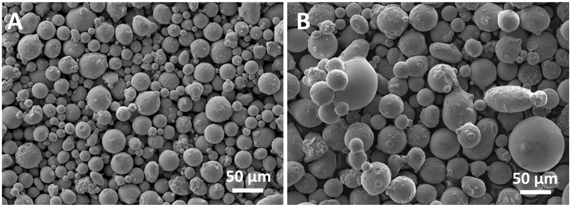
The commercial raw powder MARS F53 (UNS S32750, according to ASTM A182) produced by vacuum inert gas atomization was provided by Mimete Srl (Milano, Italy). As from the manufacturer data sheet, powder particles are spherical with a size in the range of 15–45 µm, and their nominal composition is reported in
Table 1.
Scaffolds with DO geometry were produced starting from the F53 virgin new powder by using the laser powder bed fusion (LPBF) technology in a 3D4steel manufacturing system (3D4MEC Srl, Sasso Marconi, Italy). The production system was equipped with a 300 W Yb-fiber laser operating in a nitrogen atmosphere. Optimization of printing parameters was performed producing cubic samples with 10 mm sides with variable values of laser power and scanning distance until a relative density of 98.6% was obtained. The optimized printing parameters for scaffold manufacturing are reported in
Table 2. The volume energy density (VED) corresponding to the optimized parameters is E
v = 60 J/mm
3. The scanning strategy for scaffold production involves an initial consolidation of the heart of the column and then a scan that delimits its contours. Scaffolds were studied in the as-produced condition, without any post-processing treatment. The size accuracy of the manufactured structure has a deviation from the designed dimension estimated as +/− 0.1 mm.
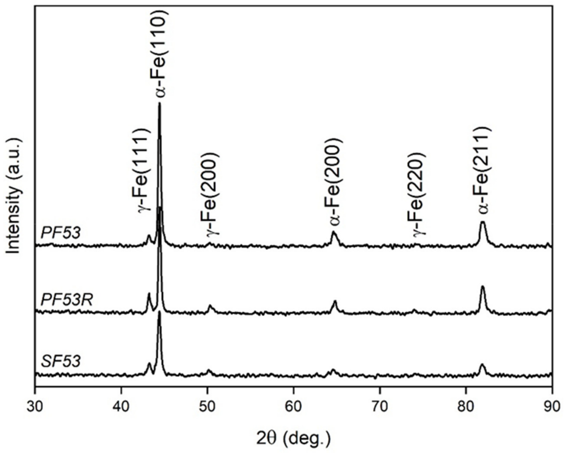
To investigate possible compositional variations of the manufactured scaffolds with respect to the virgin new powder and to evidence possible dealloying phenomena attributable to vaporization of most volatile elements during the laser melting process, the structure and composition of the residual powder inside the chamber after scaffold production were considered. Therefore, from here on the investigated samples are distinguished as: (a) PF53—virgin new powder; (b) PF53R—residual powder in the chamber after scaffold production; (c) SF53—scaffold produced from the virgin new powder.
2.3. Structural Characterization
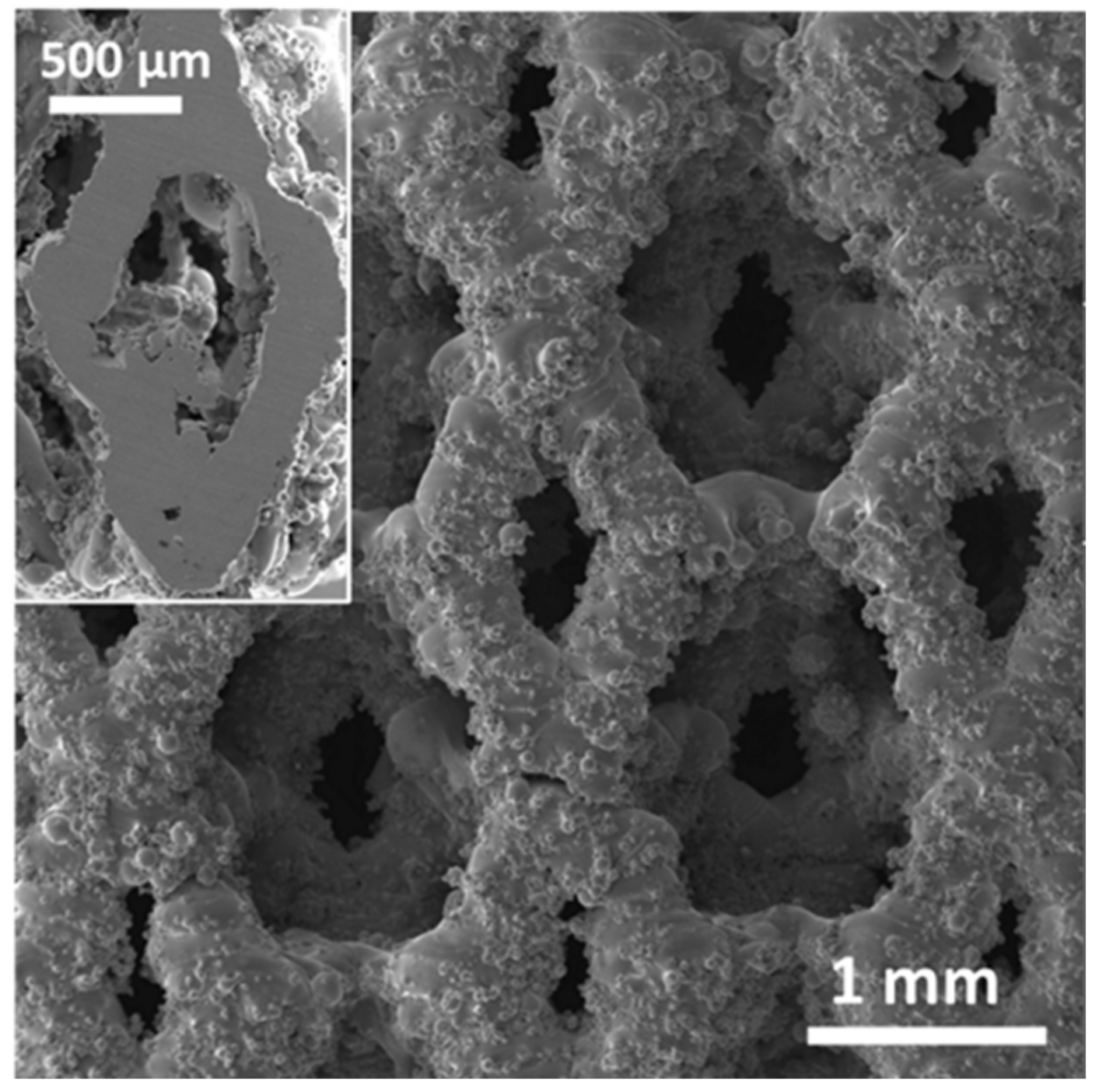
The morphology of PF53 and PF53R powders was observed using a Zeiss Supra 40 field emission scanning electron microscope (FESEM) (Carl Zeiss, Oberkochen, Germany), while the scaffold surface, inner structure, mechanical deformation and cell adhesion were investigated with a Tescan Vega 3 scanning electron microscope (SEM) (Tescan, Brno, Czech Republic). To observe the inner structure of the SF53 sample, the scaffold was cut by a diamond saw at half height, which is about 5 mm from the scaffold top surface.
A Bruker Z200 energy dispersive microanalysis (EDS) (Billerica, MA, USA) was employed to analyze the chemical composition of samples. Results were obtained by averaging the data taken from five different areas of the sample, observed at the same magnification (300×).
Information on the crystallographic structure of samples was achieved by X-ray diffraction (XRD), using a Bruker D8 Advance diffractometer (Bruker, Karlsruhe, Germany) with Cu-Kα radiation, operating at V = 40 kV and I = 40 mA, in the angular range 2θ = 30–90°. Pattern analysis was performed using the DIFFRAC.EVA software package (Version 4.3.0.1, Bruker) and peak indexing was carried out using the search/match facility using the PDF 2 database of the international center for diffraction data (ICDD). XRD peaks shape analysis including estimation of the lattice parameters of the α-Fe (ICDD 6-696) and γ-Fe (ICDD 33-397) phases calculated by nonlinear curve fitting analysis was conducted using the OriginPro 2023 software (Origin Pro, Version 2023. OriginLab Corporation, Northampton, MA, USA). The crystallite size was calculated using the Scherrer formula from the most intense peaks of phases, which are α-Fe (110) for the body centered cubic (bcc) phase and γ-Fe (111) for the face centered cubic (fcc) phase. Rietveld refinement was performed using the MAUD software, following [
20] allowed estimating the amount of phases in all the investigated samples.
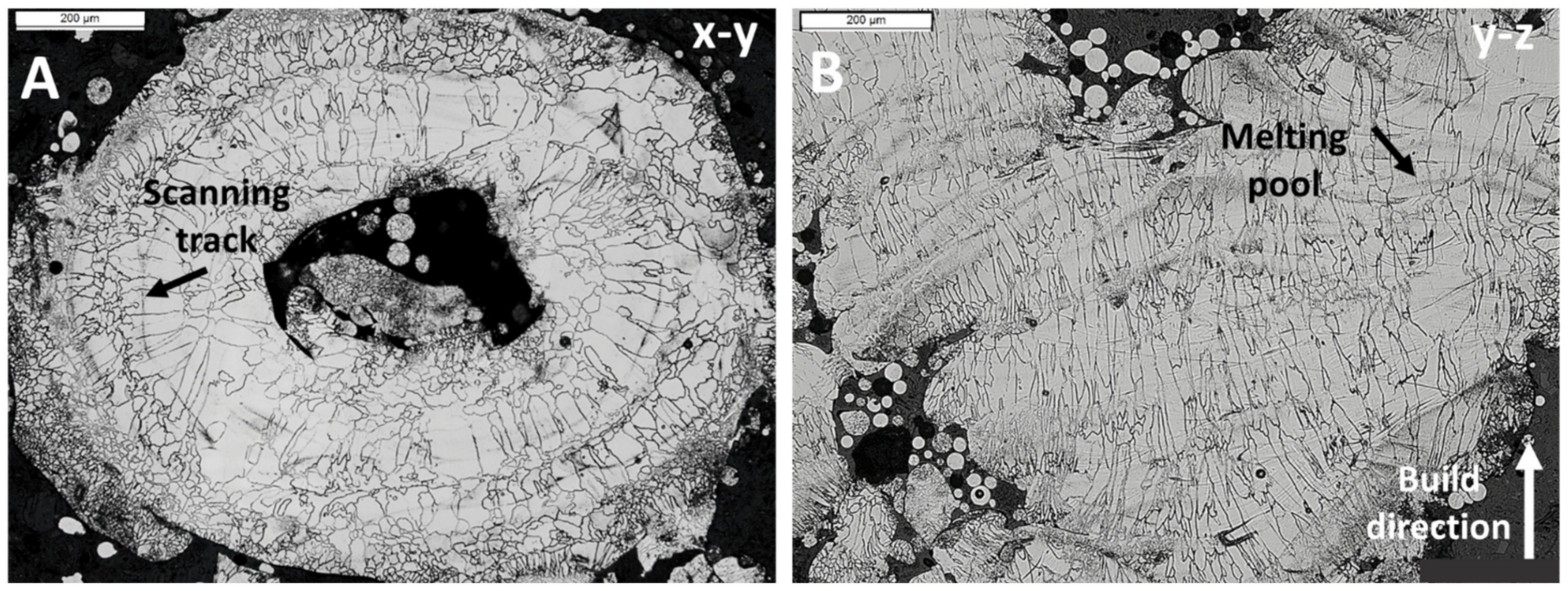
Metallographic analysis was carried out on the SF53 scaffold on the x–y plane, perpendicular to the build direction (z-axis), and on the y–z plane, along the build direction, by a Leica DMi8 optical microscope (Leica Microsystems, Wetzlar, Germany). Samples were prepared by etching in an electrolytic solution of 10 g oxalic acid in 100 mL water at 6 V for 45 s.
2.4. Mechanical Tests
Compression tests were performed on five samples of the SF53 scaffolds using an INSTRON 5567 machine (Instron, Norwood, MA, USA), with a 30 kN load cell at 0.5 mm/min speed. The test was interrupted at 30% of scaffold compression extension. Compression data were plotted as load–strain curves. The elastic modulus E was calculated using regression linear statistics in the load range of 4 to 8 kN of the stress–strain curves. Ultimate compressive strength (σUC) was determined out of the stress–strain curves.
2.5. Biological Tests
Biological tests were performed on the SF53 scaffold, using the S316L scaffold as a control.
MG-63 human osteoblast-like cells (CRL-1427, American Type Culture Collection (ATCC), Manassas, VA, USA) were maintained in Dulbecco Modified Eagle’s Medium (H-DMEM, D6429, Sigma-Aldrich, Burlington, MA, USA) with 1% penicillin–streptomycin (15140122, Thermo Fisher Scientific, Waltham, MA, USA) and 10% FBS (35-079-CV, Corning, New York, NY, USA), in a humidified incubator (Eppendorf, Hamburg, Germany) at 37 °C with 5% CO2. For passaging, trypsin/EDTA (trypsin 0.05%—EDTA 0.02% in PBS, Sigma-Aldrich, Burlington, MA, USA) was used. The medium was refreshed every three days.
The SF53 and S316L scaffolds were autoclaved at 120 °C for 20 min and then UV-exposed for 30 min on the top and bottom surfaces along the build direction. After sterilization, samples were conditioned overnight with H-DMEM with 10% FBS and 1% penicillin/streptomycin.
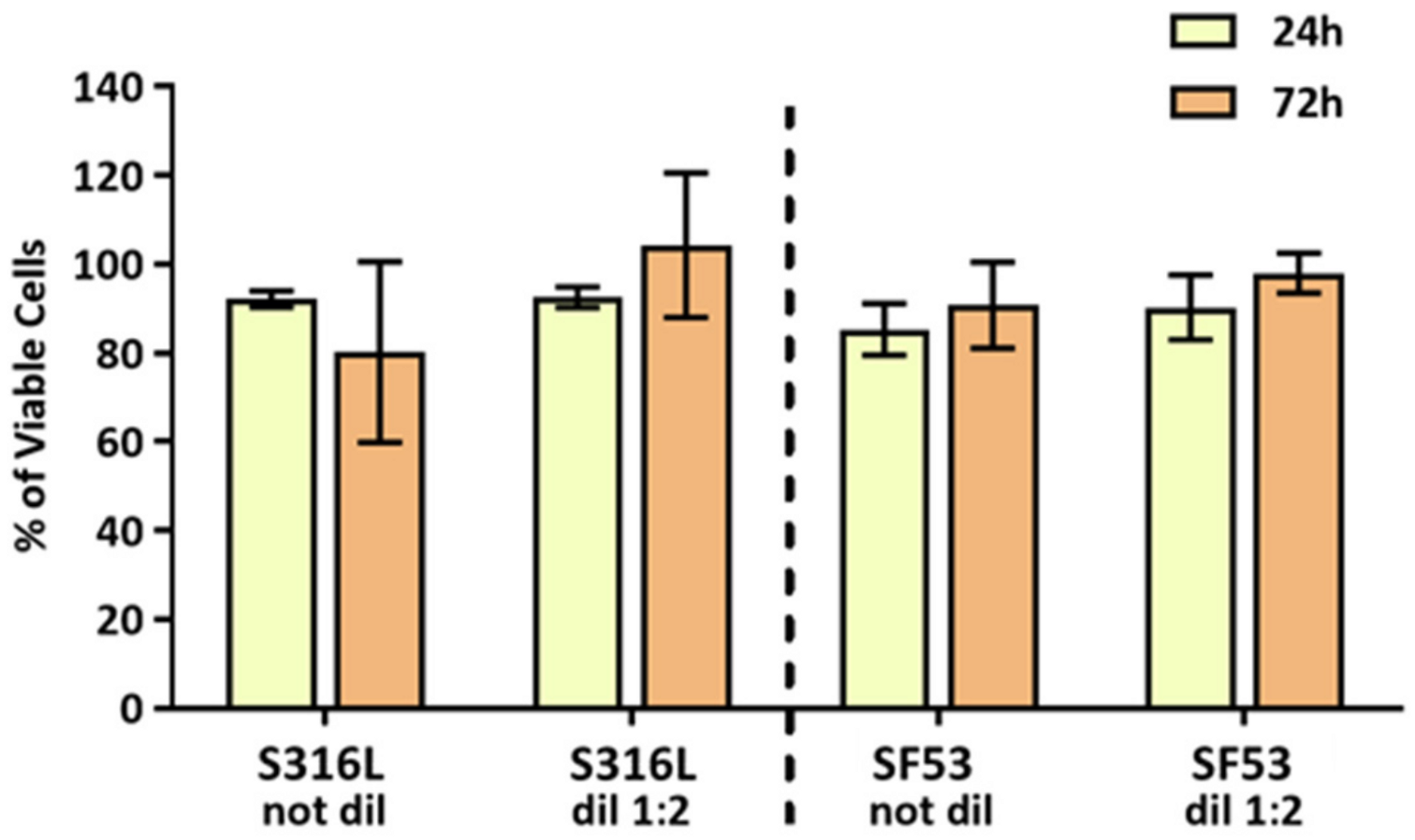
The indirect cytotoxicity of scaffolds was evaluated according to ISO 10993-12 [
21] by using the material-conditioned media (CM). MG63 were seeded at a density of 2 × 10
4 cells per well, in 96 wells/plates. After 24 h from seeding, the medium was replaced with S316L and SF53 CM or their 1:2 dilution. Then, an MTT assay was performed after 24 h and 72 h and H-DMEM was used as a control.
After the materials’ preconditioning, direct cytocompatibility tests were performed to evaluate cell–materials interaction. Each scaffold was placed in a well of 12 wells/plates and seeded with 8 × 10⁴ MG63 cells. Scaffolds were incubated at 37 °C with 5% CO2 and the medium was replaced every two days. After 24 h, 72 h and 7 d from seeding, MTT assays and SEM observations were performed on the SF53 and S316L scaffolds.
Following [
15], live and metabolically active MG63 cells were assayed by MTT (3-dimethylthiazol-2,5-diiphenyltetrazolium bromide, Sigma-Aldrich, M5655, Sigma-Aldrich, Burlington, MA, USA) according to the manufacturer’s instructions. Briefly, the MTT stock solution (5 mg/mL) was diluted 1:10 in cell culture medium and incubated at 37 °C for 3 h. After incubation, the medium was removed and 100 µL of DMSO were added to each well to dissolve the dark blue formazan crystals. Then, the absorbance was quantified by spectrophotometry (MultiskanGo, Thermo Scientific, Pittsburgh, PA, USA), monitoring the absorbance at 570 nm with a reference wavelength at 650 nm.
For ultrastructural morphology, cells were fixed in 2% glutaraldehyde (MERCK, 4239, Rahway, NJ, USA) in 0.1 M sodium cacodylate buffer (C-0250, Sigma-Aldrich, Burlington, MA, USA), followed by washes in 7% sucrose in 0.1 M cacodylate buffer. Post-fixation was carried out in 1% osmium tetroxide (Electron Microscopy Sciences, 12310, Hatfield, PA, USA) in 0.1 M sodium cacodylate buffer. Complete dehydration was achieved in graded alcohol series (from 25% to 100%) and Critical Point Dry was performed with hexamethyldisilane (HMDS, 440191, Sigma-Aldrich, Burlington, MA, USA). Scaffolds were then observed by SEM.
Three separate biological experiments were performed, and each test was conducted in triplicate. Two-way ANOVA analysis followed by Sidak’s multiple comparison test was applied to determine the differences between the experimental groups. Differences were considered statistically significant when p < 0.05.
4. Discussion
In our previous study [
15], two different graded lattice structures fabricated in 316L stainless steel (SS) by laser powder bed fusion (LPBF) were investigated, aiming to design scaffolds with improved biomechanical performances for bone tissue regeneration. Dense-in (DI) and dense-out (DO) scaffolds were obtained, varying the strut size of a rhombic dodecahedral elementary unit cell layer-by-layer, along the build direction. The strut size decreased in DI and increased in DO from the core to the edge of the scaffold, with specular symmetry relative to the central layer. The combined control of dense-out grading strategy, printing parameters and elementary unit cell geometry allowed implementing scaffolds with improved biomechanical performances. Therefore, taking as a reference the results obtained on the 316L scaffolds [
15], in this paper we report on the biomechanical response of a dense-out graded scaffold (
Figure 1) based on the F53 duplex stainless steel (DSS) and fabricated by LPBF.
According to the content of Cr, Mo and N, stainless steels show resistance to pitting corrosion, empirically quantified by the pitting resistance equivalent number (PREN), defined as PREN = Cr% + 3.3Mo% + 16N%. A higher PREN value is associated with a lower tendency to pitting corrosion, thus resulting in a useful parameter for comparing and ranking the grades of duplex stainless steels. DSSs with a PREN higher than 40 were reported to be extremely resistant to pitting corrosion and are designated as super-DSS [
22]. The F53 alloy used in this study shows a PREN ranging from 38 to 48, based on the chemical composition provided by the manufacturer (
Table 1), thus resulting in a super duplex stainless steel.
Experimental chemical composition of F53 virgin new powder (PF53) is within the range of nominal composition (
Table 3). However, the F53 scaffold fabricated with PF53 (SF53) shows a decrease in the amount of Cr and Mn, due to their preferential vaporization during the remelting process, as shown by Li et al. [
23], as the process of remelting occurs from zero to six times in LPBF 22Cr-6Ni built with a 90° rotation strategy. During the LPBF process, in the keyhole region of the melting pool, the temperature exceeds the boiling point of metal, and the vapor pressure inside the keyhole is higher than the ambient pressure. The excess pressure provides a driving force for the vapor to move away from the surface. Therefore, the convective flux of the vaporized elements contributes to the vaporization loss of elements [
24]. Specifically, the pressure-driven vaporization loss of elements occurs as follows: (I) transportation of vaporization elements from the scaffold to the surface of the melt pool; (II) vaporization of elements at the liquid–vapor interface; and (III) transportation of the vaporized elements into the surrounding atmosphere [
24]. By such a mechanism, the redeposition of vaporized Mn on the powder bed during manufacturing of SF53 occurs, as demonstrated by the increase in the Mn amount shown by the residual powder in the chamber after scaffold production.
The detailed examination of the residual powder in the chamber after scaffold production (PF53R) finds reason in the possibility of recycling powder after the LPBF process. However, recycled powder could undergo degradation, depending on the alloy chemical composition, the processing parameters employed and the building environment [
25]. For instance, the interaction between the laser and powder particles during the LPBF process leads to morphology modification of reused powder, which includes powder clusters, multiple satellites and shape-deformed particles [
25], as shown for the PF53R in
Figure 2B. Moreover, reused powder could present altered phases, likely due to the large thermal gradient in the LPBF process promoting solid-state phase transformation [
25].
In this work, a volumetric energy density (VED) value of 60 J/mm
3, resulting from the optimized printing parameters in
Table 2, allowed producing bulk samples of the F53 alloy with a relative density of 98.6% and SF53 scaffold containing 80 wt.% of the ferritic phase (
Table 4), in agreement with the literature results on microstructure evolution. Mulhi et al. [
26] in their study of the UNS S32750 DSS (2507 alloy) produced by LPBF, correlated the VED to the relative density and microstructure of samples. In particular, they found an increase of the ferrite fraction with VED from 73% at 22 J/mm
3 up to 94.7% at 429 J/mm
3. The increase of VED enhances the vaporization of austenite stabilizer elements, such as N, which causes the reduction of austenite content [
26]. Moreover, Mulhi et al. [
26] have also shown that the VED value influences the porosity of the 2507 alloy, as follows: (a) in the VED range of 22–68 J/mm
3, porosity decreases from 46% to 5%; (b) in the VED range of 68–127 J/mm
3, porosity decreases from 5% to 0.04%; and (c) in the VED range of 127–429 J/mm
3, porosity increases from 0.04% to 1.56%. From such results, Mulhi et al. [
26] identified the “process window” within which the alloy porosity due to lack of fusion, gas or metallurgical pore and the keyhole effect was minimized [
27]. Davidson et al. [
28] produced samples of the 2507 alloy by LPBF with VED in the range of 14–113 J/mm
3. The resulting samples showed randomly distributed pores, which were attributed to both insufficient melting at lower laser powers and entrapped gases at higher energy densities. The highest reported sample density was 90.8% at VED = 71 J/mm
3, with the as-built samples’ microstructure mainly formed of ferrite with small amounts of austenite preferentially located at the grain boundaries. Saeidi et al. [
29] succeeded in manufacturing samples of the 2507 alloy with a ferrite volume fraction around 75%–78% and a relative density of 99.5%, using a VED value of 127 J/mm
3. Kunz et al. [
30] reported a relative density of 99.6% with a predominantly ferritic structure, using a VED value of 24 J/mm
3.
A detailed analysis of closed and open porosity, respectively due to defects developed during the LPBF process and graded geometry [
31], was not addressed in this study. However, based on the results experimentally obtained for S316L [
15], it is expected that the open porosity of the SF53 scaffold is slightly lower than the nominal one from the STL file (P
STL = 72%). It is also noteworthy that size and distribution of the macro-pores influence the microstructure of the SF53 scaffold developed during the solidification process occurring after LPBF (
Figure 4). The macro pores act as a thermal barrier causing poor heat dissipation, thus reducing the cooling rate at the pore–material interface.
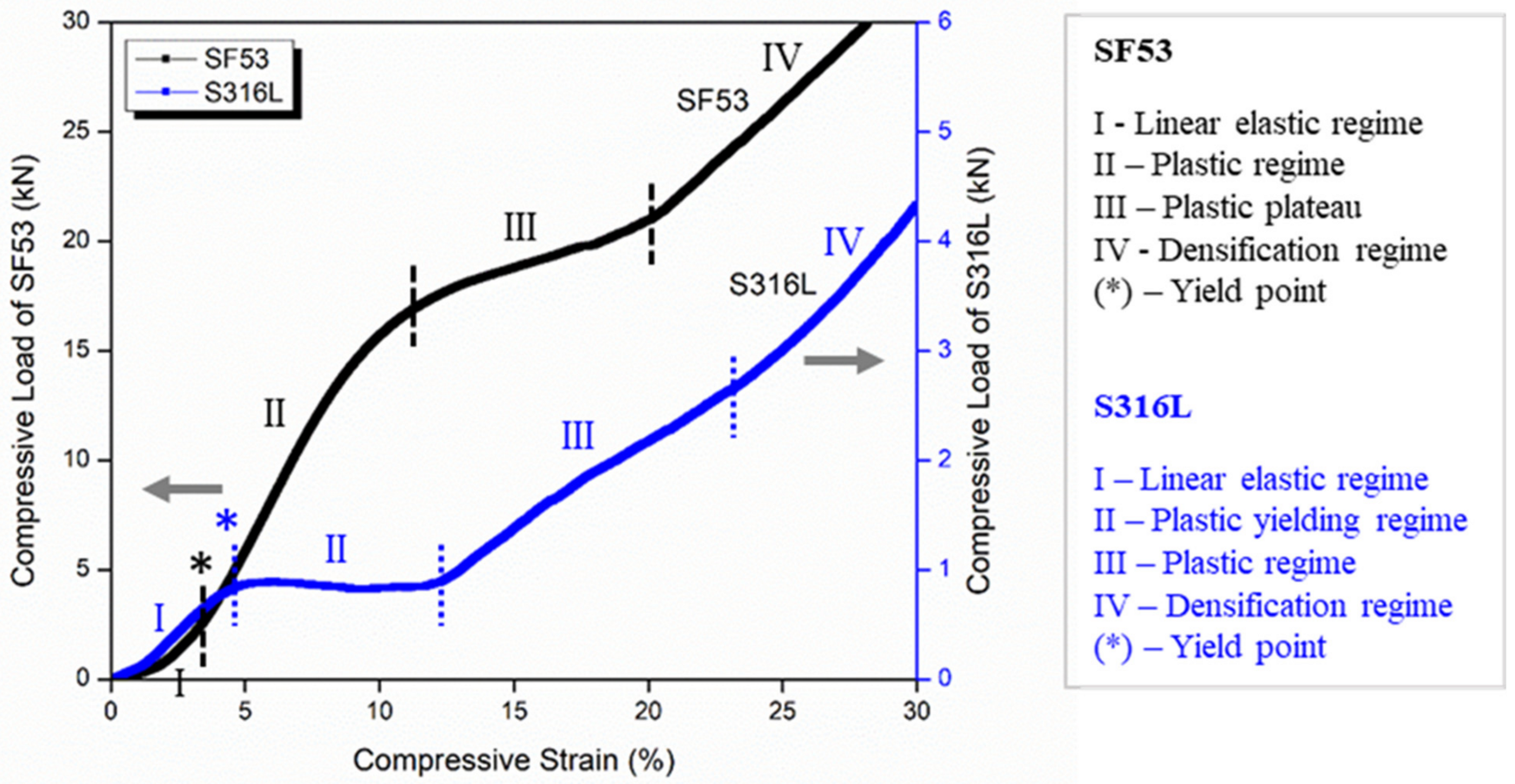
VED-driven microstructure modification is the main effect responsible for the different mechanical behaviors of SF53 and S316L, both fabricated with dense-out geometry by LPBF, using the same manufacturing system (
Figure 7a and
Figure 7c, respectively). The 316L compressive response shows different deformation mechanisms of the graded structure simultaneously activated. The lack of oscillations observed in the compression curve (
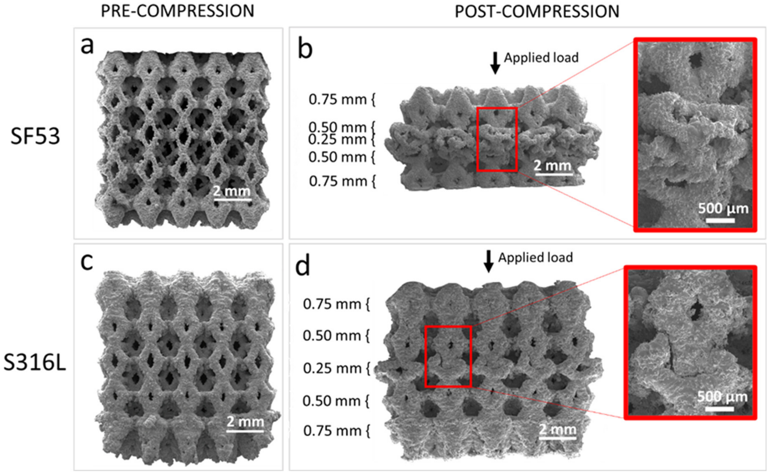
Figure 6) and the selective compaction of layers with thinner struts, as depicted in
Figure 7d, indicate that throughout the deformation process, thinner struts enter the densification regime while thicker struts remain in the plastic yielding regime. This implies that the temporal progression of deformation in S316L experiences a time shift contingent upon the size of the strut.
The SF53 plastic regime, following the initial linear behavior, starts with the gradual collapse of the layer of elementary cells with the thinner strut thickness (0.25 mm). Thus, as for S316L, the predominant failure mechanism in SF53 initiates in correspondence with the thinner struts, due to high stress concentrations on strut junctions, as also reported by Onal et al. [
32]. As the 0.25 mm struts of the three central elementary cells broke, due to the increasing compressive load, the elementary cells of the upper layer with a strut thickness of 0.50 mm interpenetrated into them (
Figure 7b), while the two external cells of the 0.25 mm layer were flattened. This latter effect is responsible for the plastic plateau response reported in
Figure 6. As the plateau trend ends, the densification of the collapsed material is responsible for the observed sharp compression increment, as for S316L (
Figure 6). As a matter of fact, SF53 shows a mechanical ultimate compressive strength (σ
UC) and elastic modulus that are respectively three times and up to seven times higher than S316L (
Table 5), whose σ
UC value is very close to the experimental value of cortical bone (as reported in [
15]).
Literature studies on 2705 DSS for bio-purposes mostly refer to corrosion behavior in simulated body fluids [
33]. From an electrochemical viewpoint, cast DSS has better performance than 18Cr-12Ni-2Mo austenitic SS because of its lower susceptibility to localized corrosion in body-simulated media [
3]. Furthermore, according to Cigada et al.’s [
4] results in physiological solution, the 2507 DSS exhibits higher corrosion resistance in artificial saliva than the 2205 DSS (UNS S32205) [
8]. The PREN of SF53 was considerably higher than that of the S316L, which ranges between 24 and 28 [
15]. However, after up to 72 h of indirect biological tests, the medium conditioned with SF53 or S316L did not induce any cytotoxic effect on MG63 viability (
Figure 8), proving the absence of the release of degradative products from both materials.
Several in vivo studies have been conducted on small animals aiming to understand the behavior of cast DSS in contact with biological tissues [
6,
13,
34]. However, in this study, an in vitro assessment of 3D cell culture response was used in replacement of experiments requiring animal sacrifice, after Rai et al. [
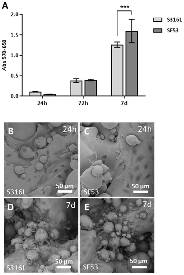
35]. The viability response of MG63 human osteoblast-like cells demonstrates that SF53 can be considered a good biocompatible material and a possible alternative to S316L for bone tissue engineering applications, allowing better viability as early as after seven days of culture (
Figure 9A). Furthermore, it is worth noting that by increasing cell culture time from 24 h (
Figure 9B,C) to seven days (
Figure 9D,E), MG63 cells preferentially spread on powder particles partially melted on the as-built scaffold surface (
Figure 3).


 ,
, 


