Investigation of Overlapped Twisted Tapes Inserted in a Double-Pipe Heat Exchanger Using Two-Phase Nanofluid

 , and
, and 
Abstract
:
1. Introduction
2. Problem Statement
2.1. Governing Equations
- Continuity equation:
- Momentum equation:where the drift velocity of the secondary phase drift is computed from:
- Energy equation:
2.2. Nanofluid Thermo-Physical Properties
2.3. Boundary Conditions and Data Deduction
3. Numerical Procedure
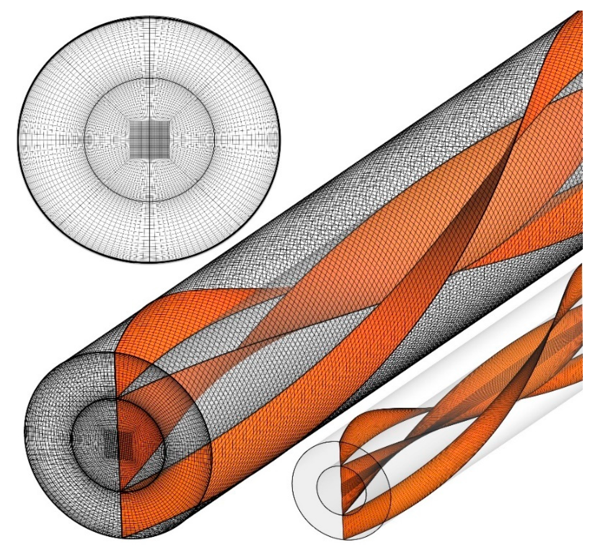
3.1. Grid Study
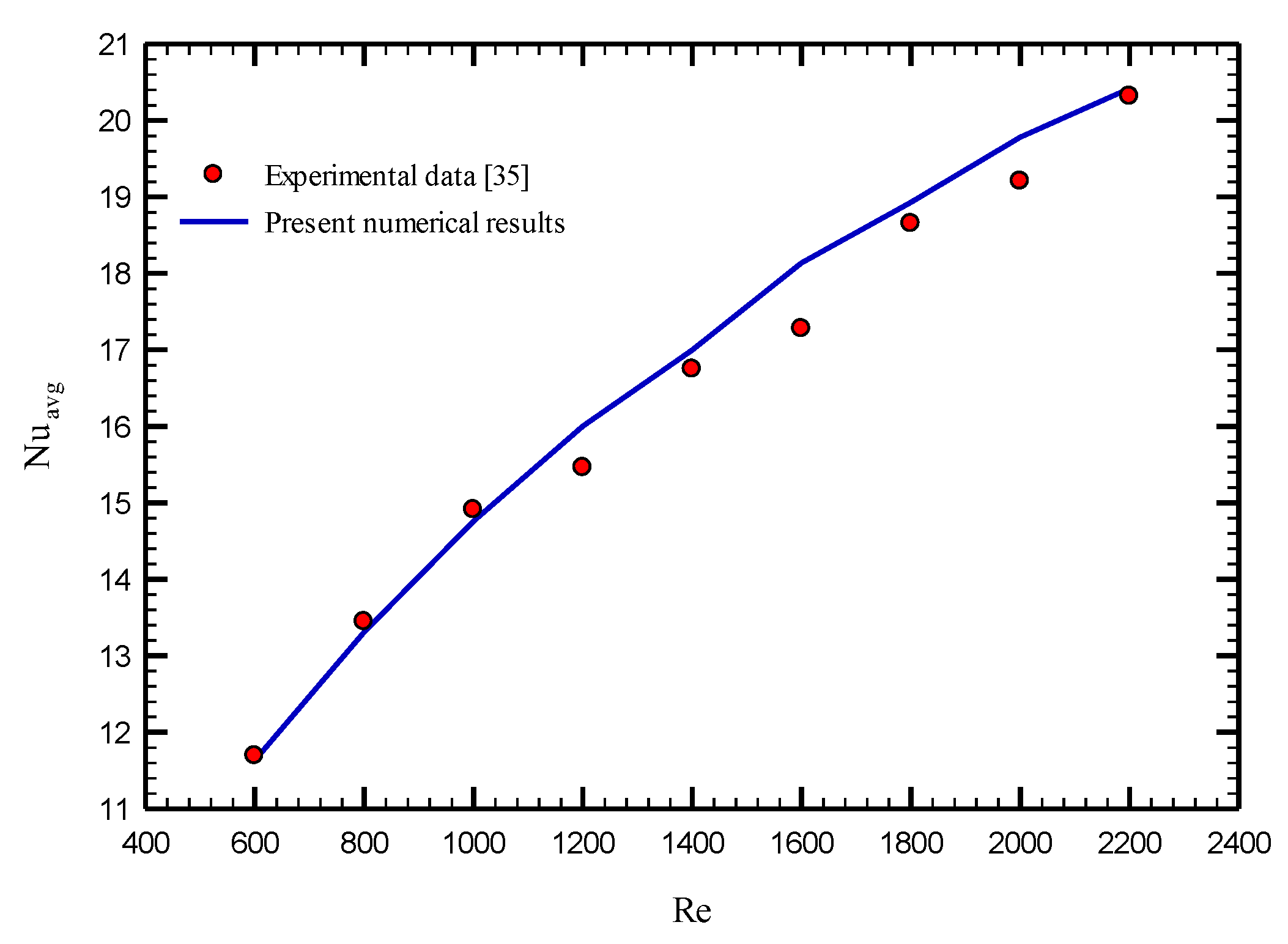
3.2. Validation
4. Results
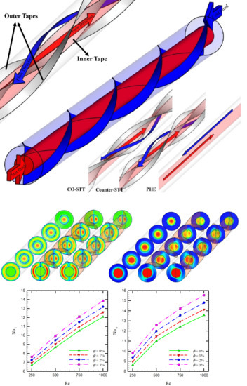
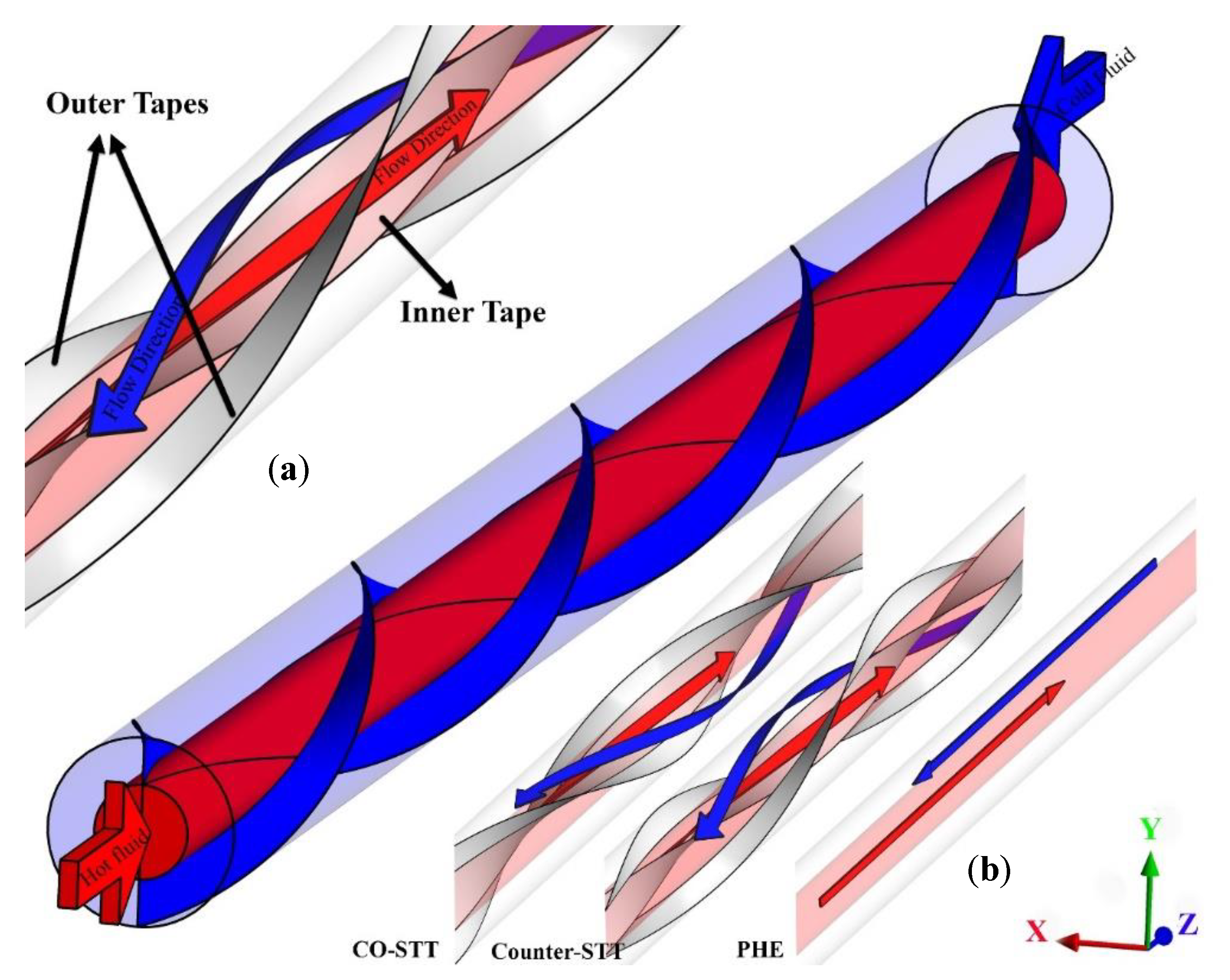
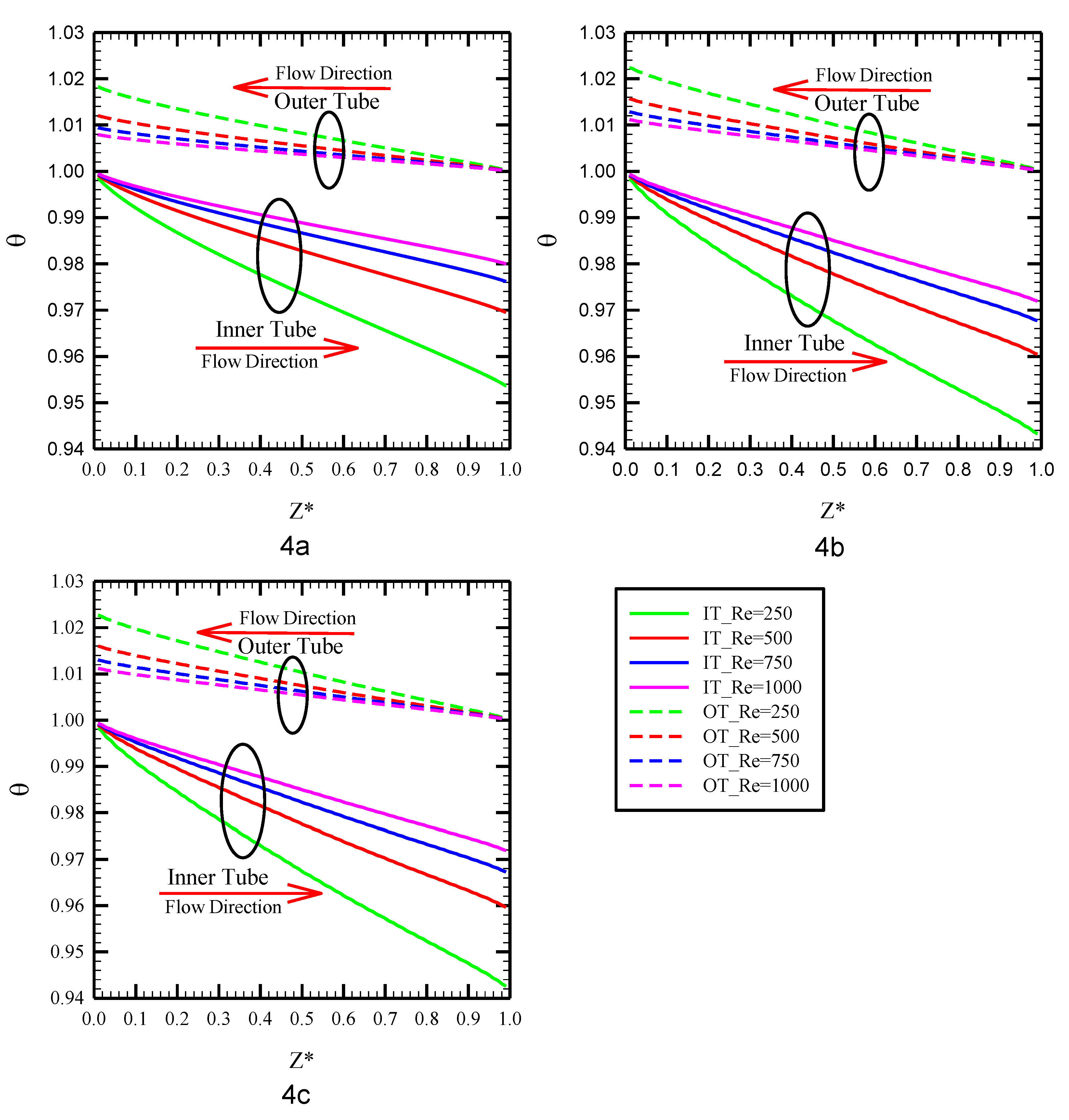
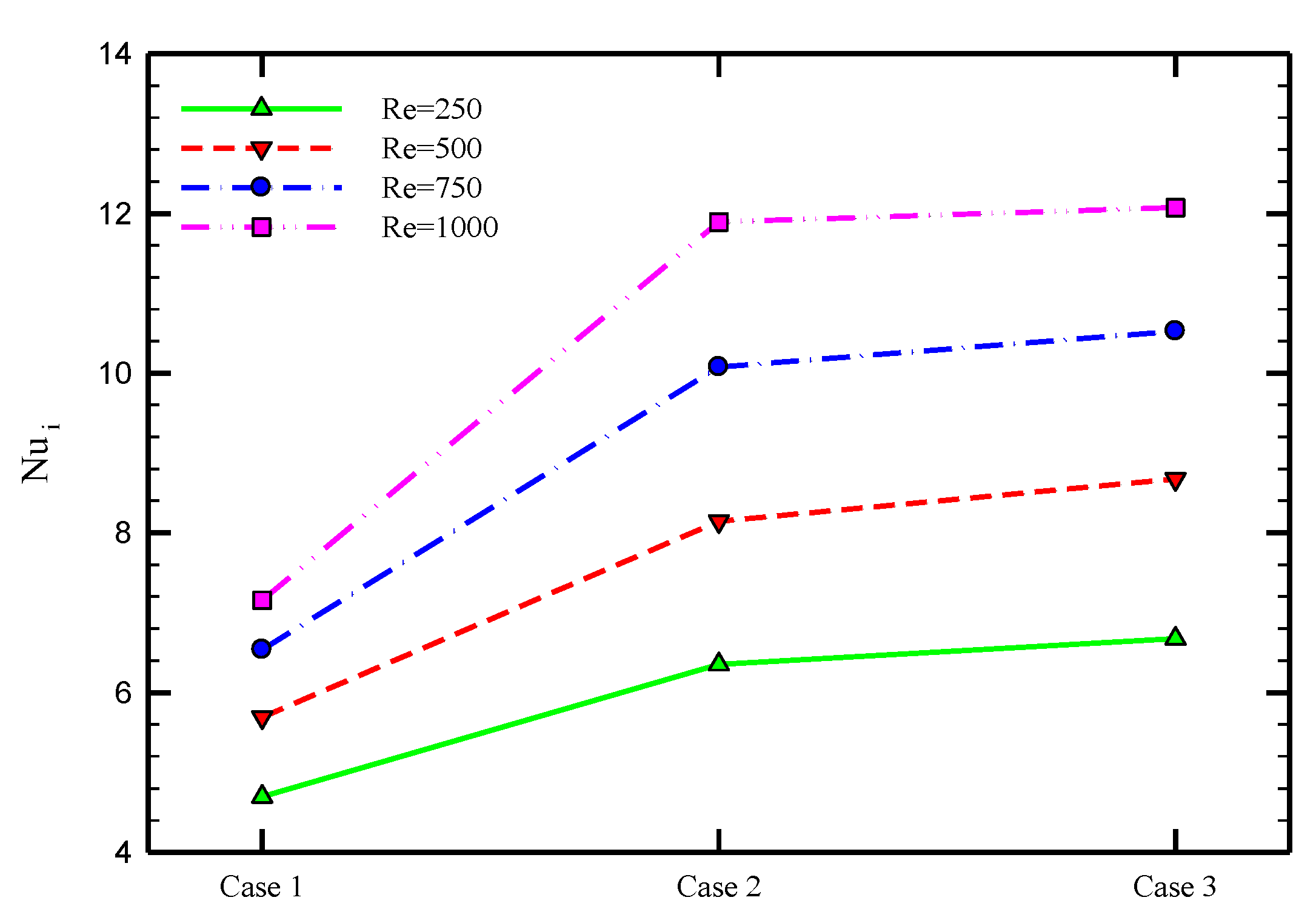
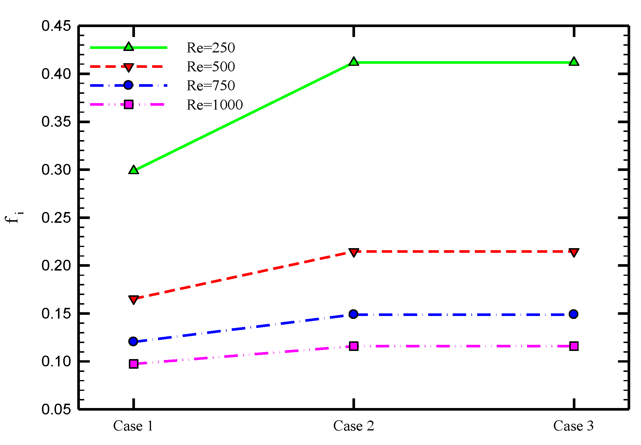
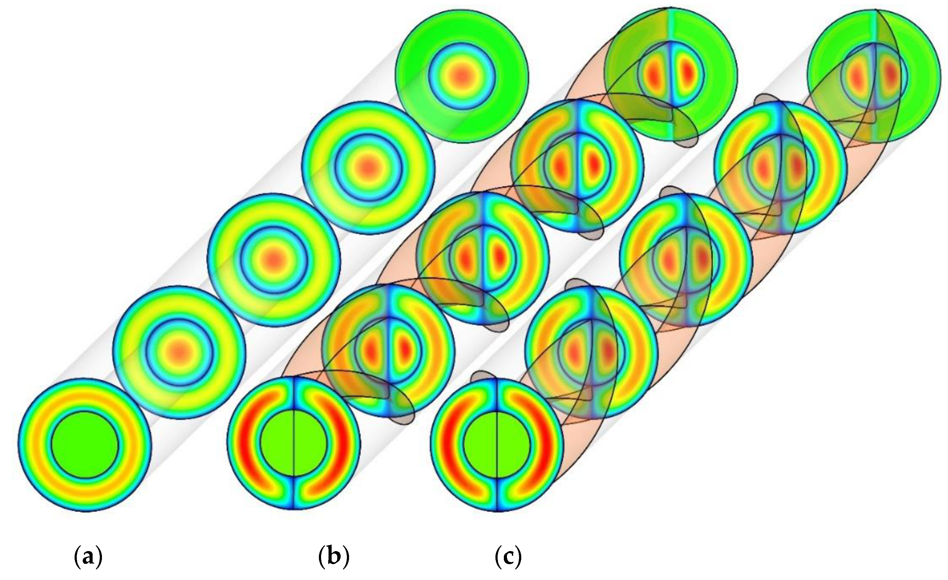
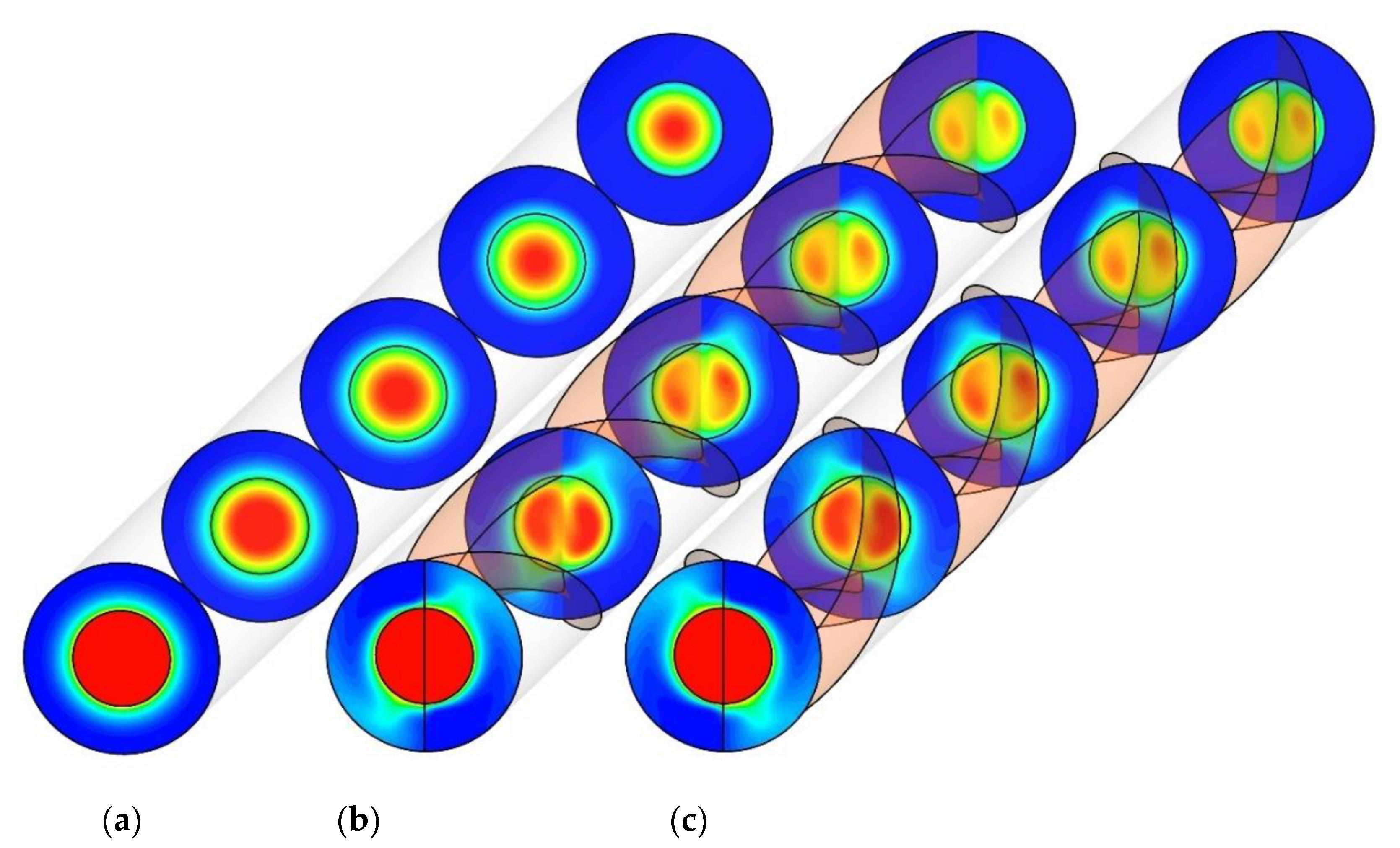
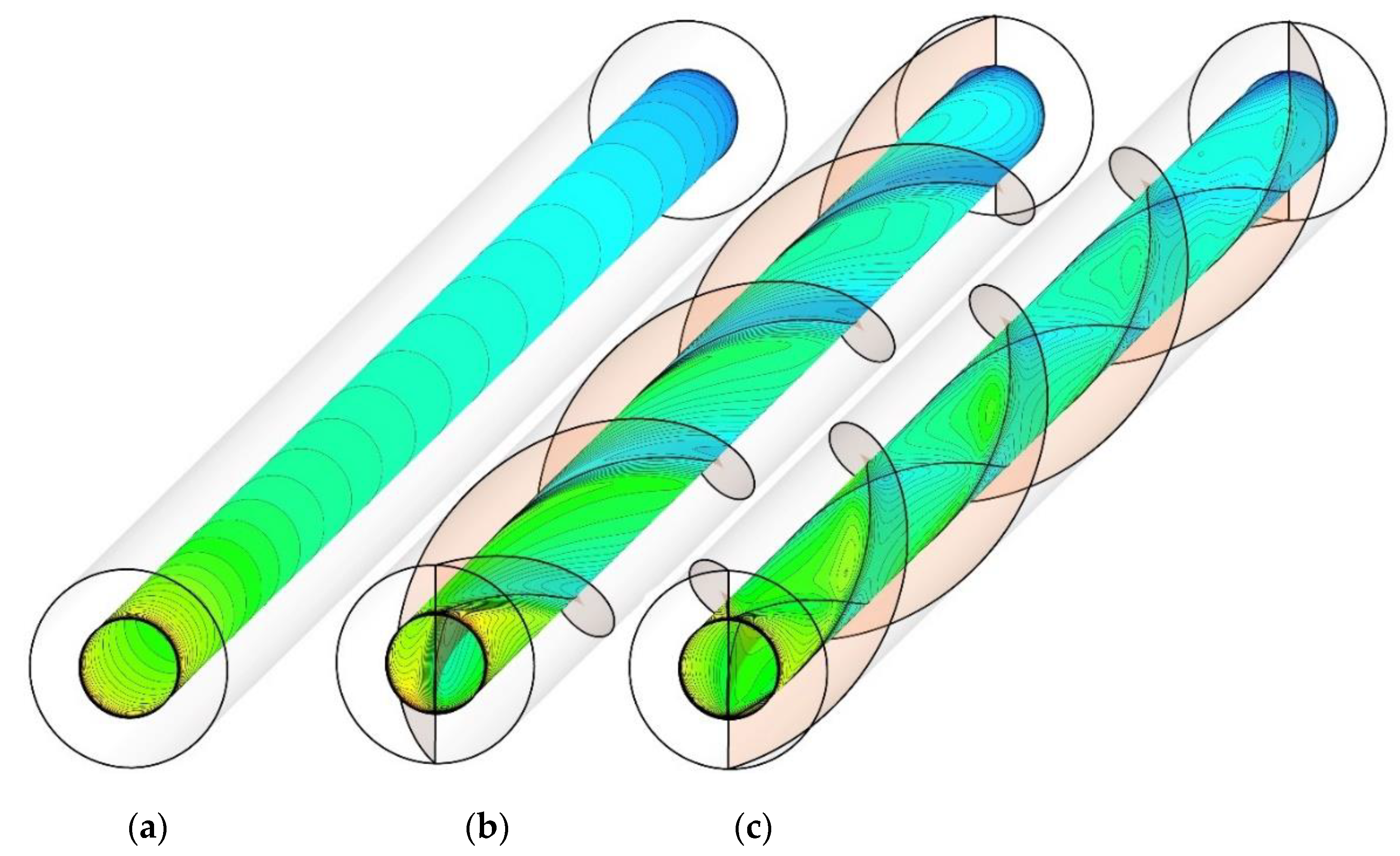
4.1. Effect of Double-Pipe Configurations
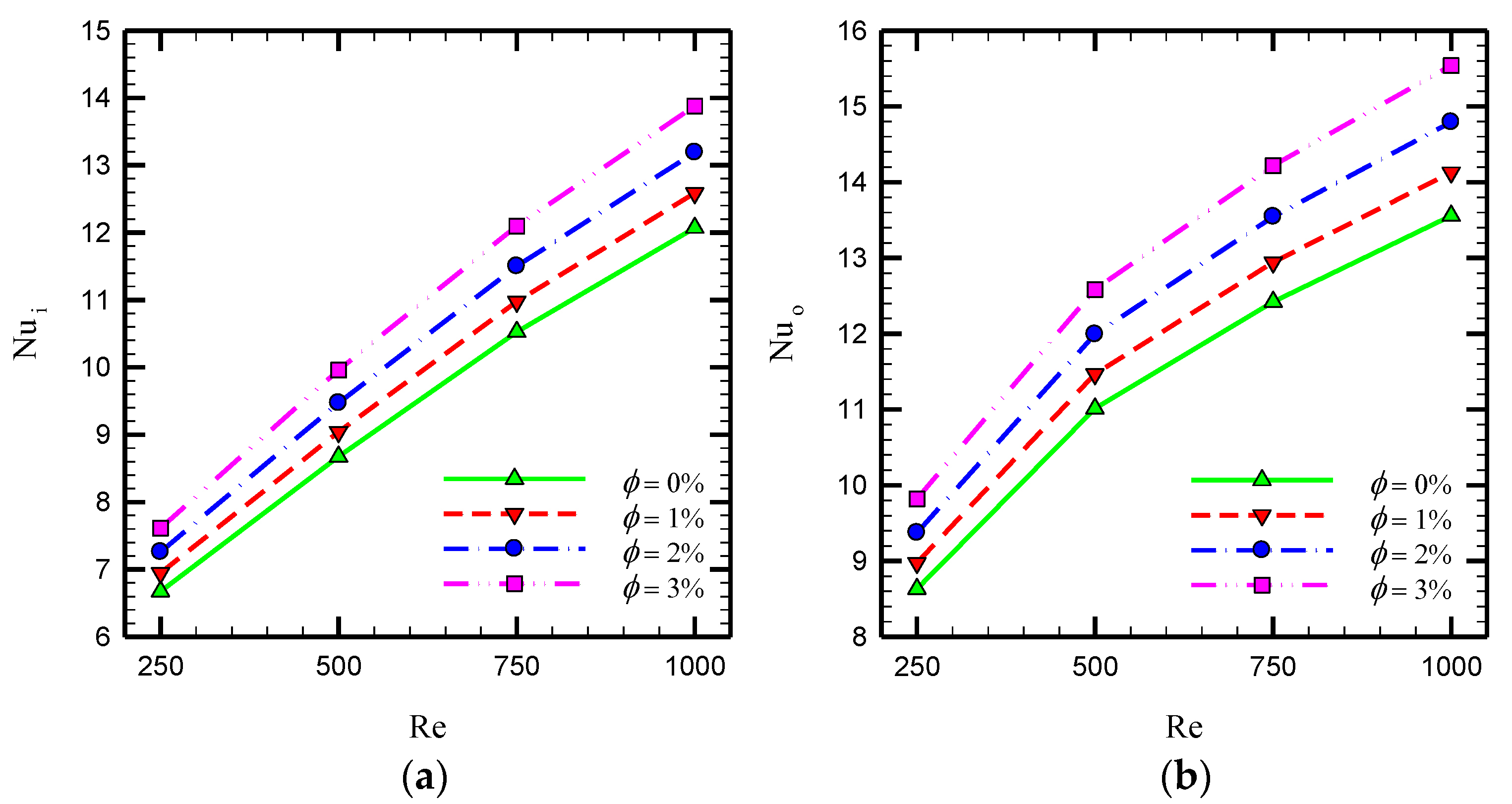
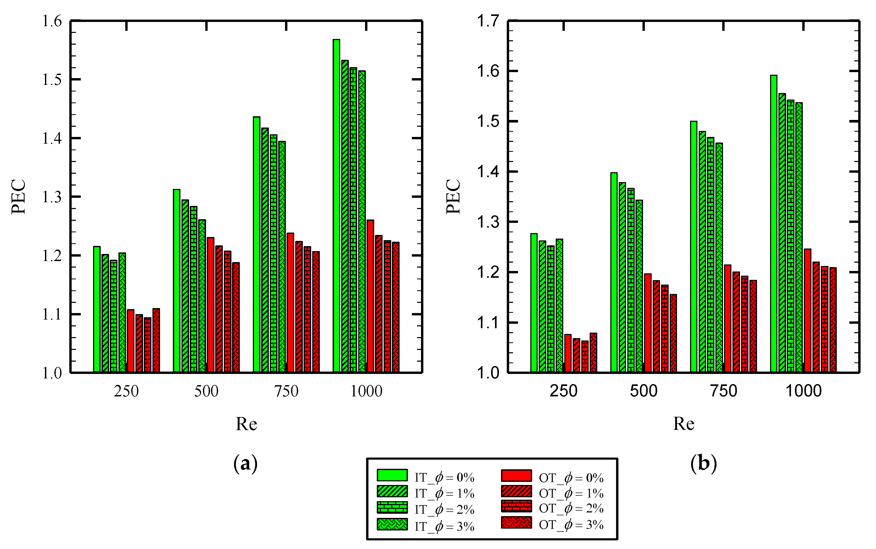
4.2. Effect of Nanoparticle Concentration on the Performance of Counter-STT Compared with Co-STT
5. Conclusions
- Using Co-STT and Counter-STT, respectively, increase the average Nusselt number by about 35.2–66.2% and 42.1–68.7% over the Reynolds number ranging 250–1000 due to the creation of secondary flow and more intense flow mixing in the presence of overlapped twisted tape inserts. Ultimately, it was shown that the highest values of PEC number are equal to 1.40 and 1.26 for the inner and outer tubes, respectively, which are found at the Reynolds number of 1000, the volume fraction of 3% and Counter-STT model. The finding of this research provides a framework for researchers working on novel combined techniques for heat transfer enhancement.
Author Contributions
Funding
Conflicts of Interest
Nomenclature
| A | area (m2) | Greek symbols | |
| cp | specific heat transfer (J/kg.K) | ϑ | kinematic viscosity (m2/s) |
| f | friction coefficient | μ | dynamic viscosity (kg/ms) |
| f0 | friction coefficient of plain channel | ρ | density (kg/m3) |
| F | body force (N) | ϕ | nanofluid concentration |
| g | gravitational acceleration (m/s2) | θ | dimensionless temperature |
| h | heat transfer coefficient (W/m2K) | Subscripts | |
| k | thermal conductivity (W/mK) | ave | average |
| n | number of phases | b | bulk |
| p | pressure (Pa) | m | mixture |
| q″ | heat flux (w/m2) | f | fluid |
| Re | Reynolds number | i | inner tube |
| T | temperature (K) | o | outer tube |
| V | velocity vector (m/s) | nf | nanofluid |
| Vdr | drift velocity | Abbreviations | |
| Vf | fluid velocity | Co-STT | co-swirling twisted tapes |
| Vp | particle velocity | Counter-STT | counter-swirling twisted tapes |
| PHE | plain heat exchanger | ||
| IT | inner tube | ||
| OT | outer tube |
References
- Hosseini, M.; Afrouzi, H.H.; Arasteh, H.; Toghraie, D. Energy analysis of a proton exchange membrane fuel cell (PEMFC) with an open-ended anode using agglomerate model: A CFD study. Energy 2019, 188, 116090. [Google Scholar] [CrossRef]
- Keshtkar, M.M.; Talebizadeh, P. Multi-Objective Optimization of a R744/R134a Cascade Refrigeration System: Exergetic, Economic, Environmental, and Sensitive Analysis (3ES). J. Therm. Eng. 2019, 5, 237–250. [Google Scholar] [CrossRef] [Green Version]
- Arshad, A.; Jabbal, M.; Sardari, P.T.; Bashir, M.A.; Faraji, H.; Yan, Y. Transient simulation of finned heat sinks embedded with PCM for electronics cooling. Therm. Sci. Eng. Prog. 2020, 18, 100520. [Google Scholar] [CrossRef]
- Boulemtafes-Boukadoum, A.; Boualbani, R.; Benzaoui, A.; El Mokretar, S. 3D numerical investigation of convective heat transfer and friction in solar air collector’s channel roughened by triangular ribs. In Proceedings of the AIP Conference Proceedings, Poznan, Poland, 11 December 2019; p. 020037. [Google Scholar] [CrossRef]
- Zhang, T.; Geng, S.; Mu, X.; Chen, J.; Wang, J.; Wu, Z. Thermal Characteristics of a Stratospheric Airship with Natural Convection and External Forced Convection. Int. J. Aerosp. Eng. 2019, 2019. [Google Scholar] [CrossRef] [Green Version]
- Bellos, E.; Tzivanidis, C. Enhancing the Performance of Evacuated and Non-Evacuated Parabolic Trough Collectors Using Twisted Tape Inserts, Perforated Plate Inserts and Internally Finned Absorber. Energies 2018, 11, 1129. [Google Scholar] [CrossRef] [Green Version]
- Chaedir, B.A.; Kurnia, J.C.; Chen, L.; Jiang, L.; Sasmito, A.P. Numerical Investigation of Ventilation Air Methane Catalytic Combustion in Circular Straight and Helical Coil Channels with Twisted Tape Insert in Catalytic-Monolith Reactors. Catalysts 2020, 10, 797. [Google Scholar] [CrossRef]
- Chougule, S.S.; Nirgude, V.V.; Sahu, S.K. Experimental study on laminar forced convection of Al2O3/water and multiwall carbon nanotubes/water nanofluid of varied particle concentration with helical twisted tape inserts in pipe flow. Heat Transf. Eng. 2018, 39, 806–818. [Google Scholar] [CrossRef]
- Gunes, S.; Karakaya, E. Thermal characteristics in a tube with loose-fit perforated twisted tapes. Heat Transf. Eng. 2015, 36, 1504–1517. [Google Scholar] [CrossRef]
- Patil, S.V.; Babu, P.V. Heat transfer and pressure drop studies through a square duct fitted with increasing and decreasing order of twisted tape. Heat Transf. Eng. 2014, 35, 1380–1387. [Google Scholar] [CrossRef]
- Wijayanta, A.T.; Mirmanto; Aziz, M. Heat transfer augmentation of internal flow using twisted tape insert in turbulent flow. Heat Transf. Eng. 2020, 41, 1288–1300. [Google Scholar] [CrossRef]
- Arasteh, H.; Mashayekhi, R.; Ghaneifar, M.; Toghraie, D.; Afrand, M. Heat transfer enhancement in a counter-flow sinusoidal parallel-plate heat exchanger partially filled with porous media using metal foam in the channels’ divergent sections. J. Therm. Anal. Calorim. 2019, 1–17. [Google Scholar] [CrossRef]
- Eisapour, M.; Eisapour, A.H.; Hosseini, M.; Talebizadehsardari, P. Exergy and energy analysis of wavy tubes photovoltaic-thermal systems using microencapsulated PCM nano-slurry coolant fluid. Appl. Energy 2020, 266, 114849. [Google Scholar] [CrossRef]
- Mehryan, S.; Ghalambaz, M.; Chamkha, A.J.; Izadi, M. Numerical study on natural convection of Ag–MgO hybrid/water nanofluid inside a porous enclosure: A local thermal non-equilibrium model. Powder Technol. 2020. [Google Scholar] [CrossRef]
- Ghalambaz, M.; Doostani, A.; Izadpanahi, E.; Chamkha, A.J. Conjugate natural convection flow of Ag–MgO/water hybrid nanofluid in a square cavity. J. Therm. Anal. Calorim. 2020, 139, 2321–2336. [Google Scholar] [CrossRef]
- Benkhedda, M.; Boufendi, T.; Tayebi, T.; Chamkha, A.J. Convective heat transfer performance of hybrid nanofluid in a horizontal pipe considering nanoparticles shapes effect. J. Therm. Anal. Calorim. 2020, 140, 411–425. [Google Scholar] [CrossRef]
- Mehryan, S.; Izadpanahi, E.; Ghalambaz, M.; Chamkha, A. Mixed convection flow caused by an oscillating cylinder in a square cavity filled with Cu–Al 2 O 3/water hybrid nanofluid. J. Therm. Anal. Calorim. 2019, 137, 965–982. [Google Scholar] [CrossRef]
- Ghalambaz, M.; Sabour, M.; Pop, I.; Wen, D. Free convection heat transfer of MgO-MWCNTs/EG hybrid nanofluid in a porous complex shaped cavity with MHD and thermal radiation effects. Int. J. Numer. Methods Heat Fluid Flow 2019, 29, 4349–4376. [Google Scholar] [CrossRef]
- Hajjar, A.; Mehryan, S.; Ghalambaz, M. Time periodic natural convection heat transfer in a nano-encapsulated phase-change suspension. Int. J. Mech. Sci. 2020, 166, 105243. [Google Scholar] [CrossRef]
- Buschmann, M.H. Nanofluid heat transfer in laminar pipe flow with twisted tape. Heat Transf. Eng. 2017, 38, 162–176. [Google Scholar] [CrossRef]
- Bahiraei, M.; Mazaheri, N.; Aliee, F. Second law analysis of a hybrid nanofluid in tubes equipped with double twisted tape inserts. Powder Technol. 2019, 345, 692–703. [Google Scholar] [CrossRef]
- Eiamsa-ard, S.; Wongcharee, K.; Kunnarak, K.; Kumar, M.; Chuwattabakul, V. Heat transfer enhancement of TiO 2-water nanofluid flow in dimpled tube with twisted tape insert. Heat Mass Transf. 2019, 55, 2987–3001. [Google Scholar] [CrossRef]
- Jaramillo, O.; Borunda, M.; Velazquez-Lucho, K.; Robles, M. Parabolic trough solar collector for low enthalpy processes: An analysis of the efficiency enhancement by using twisted tape inserts. Renew. Energy 2016, 93, 125–141. [Google Scholar] [CrossRef]
- Mwesigye, A.; Bello-Ochende, T.; Meyer, J.P. Heat transfer and entropy generation in a parabolic trough receiver with wall-detached twisted tape inserts. Int. J. Therm. Sci. 2016, 99, 238–257. [Google Scholar] [CrossRef] [Green Version]
- Esfe, M.H.; Mazaheri, H.; Mirzaei, S.S.; Kashi, E.; Kazemi, M.; Afrand, M. Effects of twisted tapes on thermal performance of tri-lobed tube: An applicable numerical study. Appl. Therm. Eng. 2018, 144, 512–521. [Google Scholar] [CrossRef]
- Sundar, L.S.; Singh, M.K.; Punnaiah, V.; Sousa, A.C. Experimental investigation of Al2O3/water nanofluids on the effectiveness of solar flat-plate collectors with and without twisted tape inserts. Renew. Energy 2018, 119, 820–833. [Google Scholar] [CrossRef]
- Lim, K.Y.; Hung, Y.M.; Tan, B.T. Performance evaluation of twisted-tape insert induced swirl flow in a laminar thermally developing heat exchanger. Appl. Therm. Eng. 2017, 121, 652–661. [Google Scholar] [CrossRef]
- Kumar, N.R.; Bhramara, P.; Kirubeil, A.; Sundar, L.S.; Singh, M.K.; Sousa, A.C. Effect of twisted tape inserts on heat transfer, friction factor of Fe3O4 nanofluids flow in a double pipe U-bend heat exchanger. Int. Commun. Heat Mass Transf. 2018, 95, 53–62. [Google Scholar] [CrossRef]
- Saysroy, A.; Eiamsa-ard, S. Periodically fully-developed heat and fluid flow behaviors in a turbulent tube flow with square-cut twisted tape inserts. Appl. Therm. Eng. 2017, 112, 895–910. [Google Scholar] [CrossRef]
- Saysroy, A.; Eiamsa-Ard, S. Enhancing convective heat transfer in laminar and turbulent flow regions using multi-channel twisted tape inserts. Int. J. Therm. Sci. 2017, 121, 55–74. [Google Scholar] [CrossRef]
- He, Y.; Liu, L.; Li, P.; Ma, L. Experimental study on heat transfer enhancement characteristics of tube with cross hollow twisted tape inserts. Appl. Therm. Eng. 2018, 131, 743–749. [Google Scholar] [CrossRef]
- Samruaisin, P.; Changcharoen, W.; Thianpong, C.; Chuwattanakul, V.; Pimsarn, M.; Eiamsa-ard, S. Influence of regularly spaced quadruple twisted tape elements on thermal enhancement characteristics. Chem. Eng. Process. Process. Intensif. 2018, 128, 114–123. [Google Scholar] [CrossRef]
- Ruengpayungsak, K.; Saysroy, A.; Wongcharee, K.; Eiamsa-Ard, S. Thermohydraulic performance evaluation of heat exchangers equipped with centrally perforated twisted tape: Laminar and turbulent flows. J. Therm. Sci. Technol. 2019, 14, JTST0002. [Google Scholar] [CrossRef]
- Hasanpour, A.; Farhadi, M.; Sedighi, K. Intensification of heat exchangers performance by modified and optimized twisted tapes. Chem. Eng. Process. Process. Intensif. 2017, 120, 276–285. [Google Scholar] [CrossRef]
- Qi, C.; Wang, G.; Yan, Y.; Mei, S.; Luo, T. Effect of rotating twisted tape on thermo-hydraulic performances of nanofluids in heat-exchanger systems. Energy Convers. Manag. 2018, 166, 744–757. [Google Scholar] [CrossRef]
- Hong, Y.; Du, J.; Wang, S. Experimental heat transfer and flow characteristics in a spiral grooved tube with overlapped large/small twin twisted tapes. Int. J. Heat Mass Transf. 2017, 106, 1178–1190. [Google Scholar] [CrossRef]
- Eiamsa-Ard, S.; Samravysin, P. Characterization of Heat Transfer by Overlapped-Quadruple Counter Tapes. J. Heat Transf. 2018, 140. [Google Scholar] [CrossRef]
- Rudrabhiramu, R.; Kumar, K.H.; Kumar, K.K.; Rao, K.M. Heat Transfer Enhancement Using Overlapped Dual Twisted Tape Inserts with Nanofluids. In Advances in Applied Mechanical Engineering; Springer: New York, NY, USA, 2020; pp. 123–130. [Google Scholar] [CrossRef]
- Manninen, M.; Taivassalo, V.; Kallio, S. On the Mixture Model for Multiphase Flow; Technical Research Centre of Finland: Espoo, Finland, 1996. [Google Scholar]
- Goossens, W.R.A. Review of the empirical correlations for the drag coefficient of rigid spheres. Powder Technol. 2019, 352, 350–359. [Google Scholar] [CrossRef]
- Khanafer, K.; Vafai, K. A critical synthesis of thermophysical characteristics of nanofluids. Int. J. Heat Mass Transf. 2011, 54, 4410–4428. [Google Scholar] [CrossRef]
- Bianco, V.; Manca, O.; Nardini, S.; Vafai, K. Heat Transfer Enhancement with Nanofluids; CRC Press: Boca Raton, FL, USA, 2015. [Google Scholar]
- Maiga, S.E.B.; Palm, S.J.; Nguyen, C.T.; Roy, G.; Galanis, N. Heat transfer enhancement by using nanofluids in forced convection flows. Int. J. Heat Fluid Flow 2005, 26, 530–546. [Google Scholar] [CrossRef]


| Nanoparticle Properties | ||||
| 3880 | 733 | 36 | - | |
| Nanofluid Properties | ||||
| 998.2 | 4182 | 0.6 | 1.00 × 10−03 | |
| 1027.018 | 4147.51 | 0.616618 | 0.001089 | |
| 1055.836 | 4113.02 | 0.633833 | 0.001199 | |
| 1084.654 | 4078.53 | 0.651644 | 0.001334 | |
| Case | Number of Elements | Nusselt Number | Error (%) |
|---|---|---|---|
| 3 | 2,000,000 | 15.53 | - |
| 4 | 2,750,000 | 14.36 | 7.53 |
| 5 | 3,500,000 | 13.87 | 3.41 |
| 6 | 4,250,000 | 13.65 | 1.59 |
| 7 | 5,000,000 | 13.55 | 0.73 |
| Experimental Data [35] | Present Numerical Results | Error (%) |
|---|---|---|
| 11.6901 | 11.6316 | 0.5004 |
| 13.4444 | 13.31 | 0.9997 |
| 14.9064 | 14.7573 | 1.0002 |
| 15.462 | 16.0032 | 3.5002 |
| 16.7485 | 16.9997 | 1.4999 |
| 17.2749 | 18.1386 | 4.9998 |
| 18.6491 | 18.9288 | 1.4998 |
| 19.2047 | 19.7808 | 2.9998 |
| 20.3158 | 20.4174 | 0.5001 |
© 2020 by the authors. Licensee MDPI, Basel, Switzerland. This article is an open access article distributed under the terms and conditions of the Creative Commons Attribution (CC BY) license (http://creativecommons.org/licenses/by/4.0/).
Share and Cite
Ghalambaz, M.; Arasteh, H.; Mashayekhi, R.; Keshmiri, A.; Talebizadehsardari, P.; Yaïci, W. Investigation of Overlapped Twisted Tapes Inserted in a Double-Pipe Heat Exchanger Using Two-Phase Nanofluid. Nanomaterials 2020, 10, 1656. https://0-doi-org.brum.beds.ac.uk/10.3390/nano10091656
Ghalambaz M, Arasteh H, Mashayekhi R, Keshmiri A, Talebizadehsardari P, Yaïci W. Investigation of Overlapped Twisted Tapes Inserted in a Double-Pipe Heat Exchanger Using Two-Phase Nanofluid. Nanomaterials. 2020; 10(9):1656. https://0-doi-org.brum.beds.ac.uk/10.3390/nano10091656
Chicago/Turabian StyleGhalambaz, Mehdi, Hossein Arasteh, Ramin Mashayekhi, Amir Keshmiri, Pouyan Talebizadehsardari, and Wahiba Yaïci. 2020. "Investigation of Overlapped Twisted Tapes Inserted in a Double-Pipe Heat Exchanger Using Two-Phase Nanofluid" Nanomaterials 10, no. 9: 1656. https://0-doi-org.brum.beds.ac.uk/10.3390/nano10091656