
A Facile Chemical Method Enabling Uniform Zn Deposition for Improved Aqueous Zn-Ion Batteries


Leibniz Institute for Solid State and Materials Research (IFW) Dresden e.V., 01069 Dresden, Germany
*
Authors to whom correspondence should be addressed.
†
These authors contributed equally to this work.
Nanomaterials 2021, 11(3), 764; https://0-doi-org.brum.beds.ac.uk/10.3390/nano11030764
Submission received: 26 February 2021
/
Revised: 15 March 2021
/
Accepted: 16 March 2021
/
Published: 18 March 2021
(This article belongs to the Special Issue Nanomaterials for Ion Battery Applications)
Abstract
:Rechargeable aqueous Zn-ion batteries (ZIBs) have gained great attention due to their high safety and the natural abundance of Zn. Unfortunately, the Zn metal anode suffers from dendrite growth due to nonuniform deposition during the plating/stripping process, leading to a sudden failure of the batteries. Herein, Cu coated Zn (Cu–Zn) was prepared by a facile pretreatment method using CuSO4 aqueous solution. The Cu coating transformed into an alloy interfacial layer with a high affinity for Zn, which acted as a nucleation site to guide the uniform Zn nucleation and plating. As a result, Cu–Zn demonstrated a cycling life of up to 1600 h in the symmetric cells and endowed a stable cycling performance with a capacity of 207 mAh g−1 even after 1000 cycles in the full cells coupled with a V2O5-based cathode. This work provides a simple and effective strategy to enable uniform Zn deposition for improved ZIBs.
1. Introduction
The significantly growing consumption of fossil fuels worldwide has led to severe global warming. To reduce the usage of fossil fuels and sustainably develop renewable energy utilization, e.g., solar energy and wind energy, advanced energy storage systems (such as batteries and supercapacitors) are in high demand [1,2,3,4]. For example, lithium-ion batteries (LIBs) have seen tremendous success as one of the most common types of power source in the portable electronics market, due to their high energy density [5,6,7]. However, the fire risk of the flammable organic electrolyte, high cost, as well as limited reserves of lithium, severely restrict the largescale implementation of LIBs in automotive and stationary storage applications [8,9]. In this regard, developing alternative battery technology is important and essential. Recently, rechargeable aqueous Zn-ion batteries (ZIBs) have been increasingly investigated, due to their low cost, the high theoretical capacity of zinc (819 mAh g−1), and the low redox potential (−0.762 V vs. SHE). More importantly, the aqueous electrolyte possesses the merits of nonflammable, nontoxic, and environmental benignity [10,11,12]. However, ZIBs suffer from a challenging issue related to the zinc anode, which is afflicted with uncontrollable dendrite formation during the Zn stripping/plating process. The problem is generally attributed to what is known as the “tip effect”, where, due to charge aggregation near the protuberances on the inhomogeneous zinc surface, zinc ions are easily absorbed onto the protruded tips and nucleate preferentially on these spots, thereby triggering continuous growth and finally form Zn dendrites [13,14,15,16].
To address this issue, various methods have been developed, such as optimizing the electrolytes [17], stabilizing the structure by employing host materials [18], and modifying the surface [19,20,21,22,23,24]. Among surface modification methods, an efficient strategy to stabilize the Zn anode during the stripping/plating process is a surface coating with a metal such as In [19], Au [20], Ag [21], and Cu [21] coating, which acts as a nucleation site to guide uniform Zn deposition. For instance, Zhang et al. developed Ag and Cu coatings on Zn metal through the thermal evaporation method [21]. They found out that Ag−Zn and Cu–Zn alloys were formed after cycling, which improved the affinity to Zn and further contributed to the uniform nucleation and deposition of Zn. Owing to its easy alloy formation with Zn and low cost, Cu is a promising material for Zn stabilization as compared with noble metals such as Ag and Au. However, the high temperature required in the thermal evaporation method would not enable cost efficiency and would limit largescale applicability. Consequently, developing direct, economically viable methods to fabricate an effective Cu coating on Zn metal is required for the practical application of ZIBs. From the point of view of efficacy and cost, chemical methods may be a good alternative. Therefore, Cu coating on Zn metal prepared by a chemical route to guide uniform Zn nucleation and deposition is a meaningful route to explore.
In this work, Cu coated Zn (Cu–Zn) was prepared by a facial chemical method. Cu coating was transformed to Cu–Zn alloy after cycling, which acted as the nucleation sites to guide uniform Zn nucleation and deposition. As a result, Cu–Zn not only showed improved cycling life in the symmetric cells, but also enabled a stable cycling performance in the full cells coupled with V2O5-based cathode. The results demonstrated that our strategy was facile and efficient to guide uniform Zn deposition for improved ZIBs.
2. Materials and Methods
2.1. Preparation of the Cu Coated Zn
A pristine zinc foil (125 μm in thickness, Goodfellow GmbH, Bad Nauheim, Germany) was polished with sandpaper and then cut into discs with a diameter of 12 mm. A portion of 100 µL of 0.1 M copper sulfate (CuSO4, 99.99%, Sigma-Aldrich, St Louis, MO, USA) aqueous solution was dropped on the zinc disc surface and kept for 3 min to get a one-side-coated Zn foil. The treated zinc metal was washed with deionized water a few times and stored in the air to dry naturally.
2.2. Preparation of Poly(3,4-ethylenediophene)-Coated V2O5 (V2O5-PEDOT) Cathode
For the synthesis of V2O5-PEDOT, 7 g of commercial V2O5 powder (Sigma-Aldrich, St Louis, MO, USA) was dispersed in 70 mL of deionized water, then 1 mL of 3,4-ethylenediophene (EDOT, Aladdin, Shanghai, China) was added dropwise. The mixture was continuously stirred for 6 days and filtered. The obtained powder was dried in a vacuum oven at 70 ℃ for overnight [25]. The cathode was prepared by coating the slurry of V2O5-PEDOT, Super C65 (TIMCAL, Bodio, Switzerland), and polyvinylidene fluoride (PVDF, Solef 21216, Solvay, Milan, Italy) in N-methyl pyrrolidone (99%, NMP, Sigma-Aldrich, St Louis, MO, USA) at a mass ratio of 8:1:1 on to stainless steel mesh (500 pores per linear inch, wire diameter of 0.2 mm, Gelon lib group, Linyi, China) and dried in a vacuum at 80 °C overnight. The mass loading of V2O5-PEDOT was about 1 mg∙cm−1.
2.3. Characterization
A scanning electron microscope (FFG-SEM, Zeiss-Leo Gemini 1530, Carl Zeiss NTS GmbH, Oberkochen, Germany) was employed to characterize the surface morphologies of zinc electrodes at different stages of the experiment process. Elemental mappings were performed using energy dispersive X-ray spectroscopy with a Bruker XFlash 6 detector (Bruker, Karlsruhe, Germany). X-ray diffraction (XRD) was carried out on a Panalytical X’pert Pro diffractometer device (Panalytical, Almelo, Netherlands) operating with Co Kα radiation in reflection mode. The X-ray photoelectron spectroscopy (XPS) analysis was performed in a PHI 1600 ESCA (PerkinElmer, Waltham, MA, USA) spectrometer with a monochromatic Al-Kα source. The binding energies were calibrated using the C 1s peak at 284.8 eV.
2.4. Electrochemical Characterization
The ZIBs were assembled using Swagelok cells under ambient conditions in air. 3 M Zn (CF3SO3)2 (98%, Sigma-Aldrich, St Louis, MO, USA) aqueous solution and glass fiber (Whatman GF/D, Whatman, Clifton, NJ, USA) were used as electrolyte and separator, respectively. The galvanostatic cycling of symmetric cells was performed with different current densities using LAND CT2001A (Wuhan Land Electronic Co., Ltd., Wuhan, China) potentiostat. The galvanostatic cycling performance of full cells was tested in the voltage range of 0.3 V ≤ U ≤ 1.6 V vs. Zn/Zn+ using LAND potentiostat.
3. Results
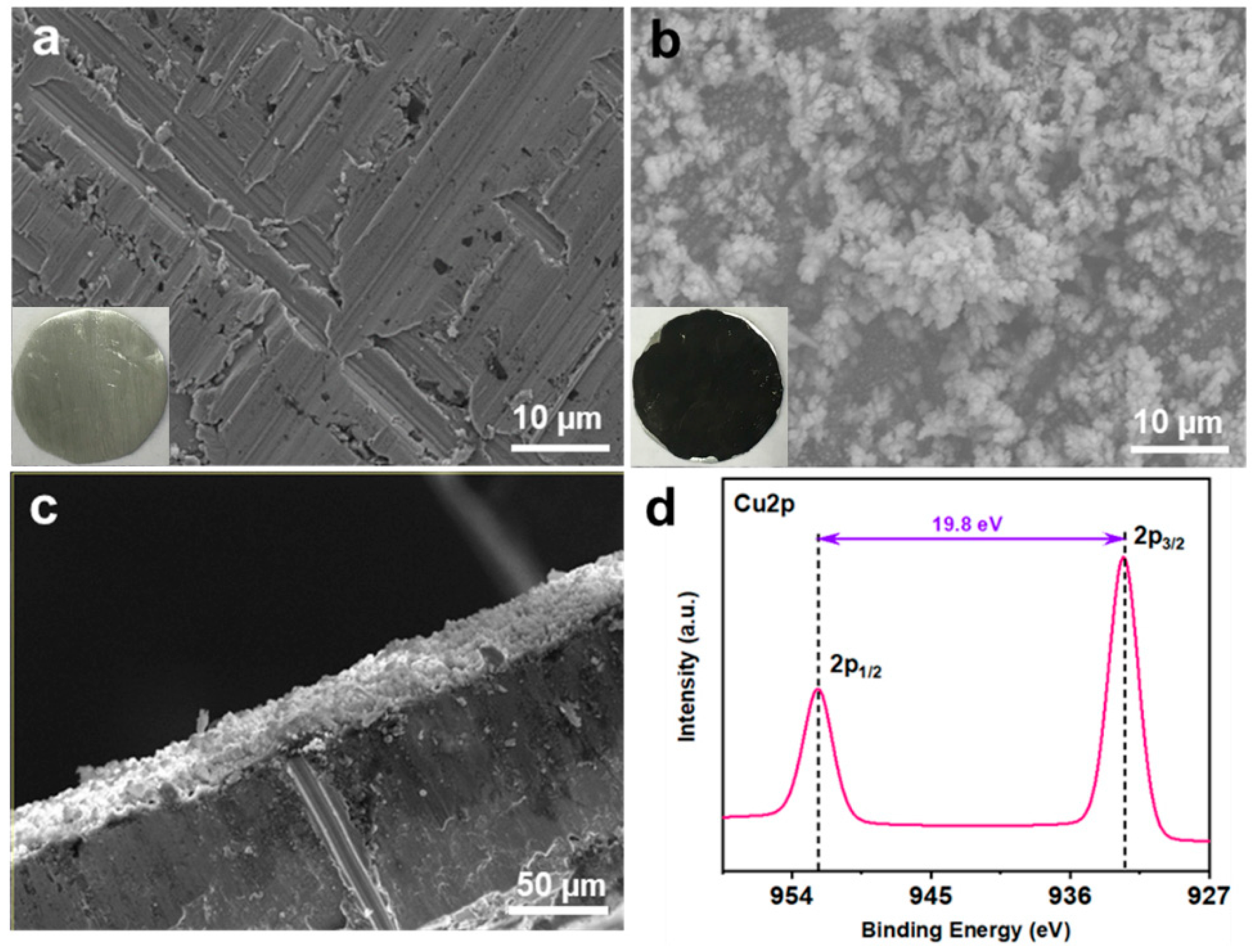
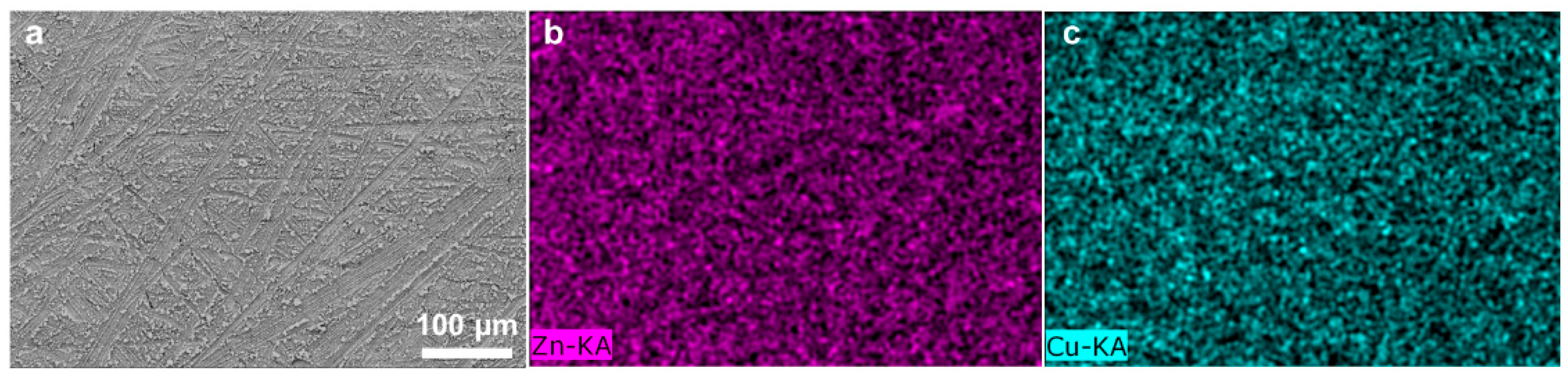
Cu-coated Zn (Cu–Zn) was prepared via an in situ chemical method by dropping an aqueous CuSO4 solution on bare zinc foils. The treated Zn foils were subsequently washed and dried. Due to the potential difference between Zn2+/Zn and Cu2+/Cu, a spontaneous replacement reaction occurred and the surface of Zn changed to a black color after treatment (insets of Figure 1a,b). Scanning electron microscopy (SEM) was conducted to characterize the morphology of bare Zn and Cu–Zn. The bare zinc had a rough and scratched surface with a unique texture due to the polish process (Figure 1a). Cu–Zn clearly showed a coated surface (Figure 1b). The elemental mapping of Cu–Zn showed Cu uniformly distributed on the surface of Zn (Figure 2). The thickness of the Cu coating layer was about 20 µm by the cross-section SEM image (Figure 1c). The high resolution Cu 2p XP spectrum of Cu–Zn showed two peaks located at 932.5 eV and 952.3 eV, assigned to metallic Cu (Figure 1d) [26]. It should be noted that it was challenging to distinguish between the metallic Cu and Cu(I) by binding energy of Cu 2p, as the Cu 2p signals overlapped. Although the Cu LMM Auger peak is recommended to be used for the identification and analysis of Cu(I), unfortunately, the intensity of the signal in the Cu LMM Auger region of Cu–Zn was too weak for further analysis [27]. However, in our case since the reaction represented a chemical reduction of Cu(II), the formation of Cu(I) was highly unlikely.
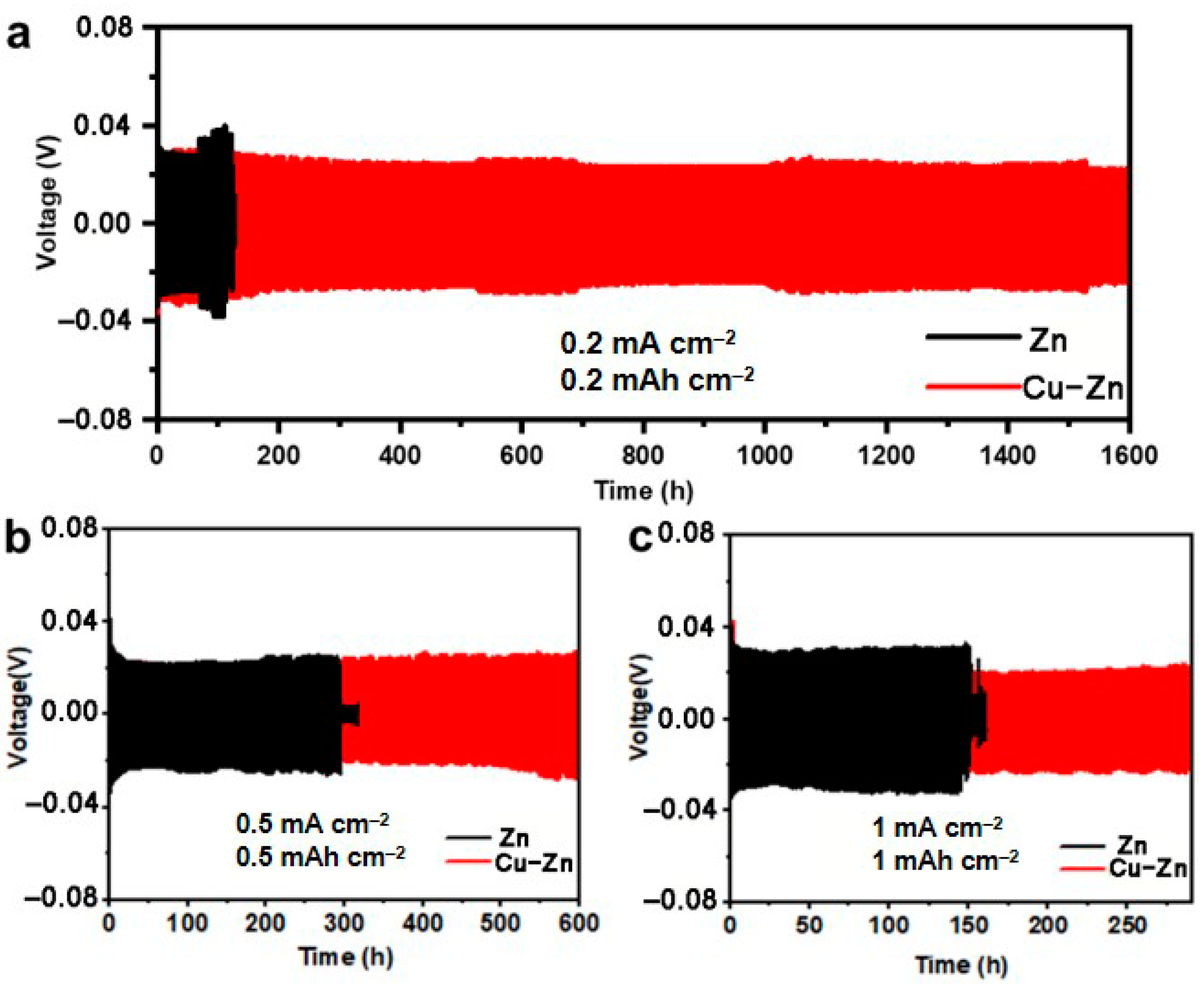
In order to evaluate the effect of the Cu coating on the Zn plating/stripping behavior, symmetric cells comprised of bare Zn and Cu–Zn (henceforth referred to Zn//Zn and Cu-Zn//Cu–Zn respectively) were assembled and tested. Galvanostatic charge/discharge was performed at different current densities. At 0.2 mA cm−2, the Zn//Zn cell exhibited an increasing overpotential after 70 h cycling, subsequently showing an abnormal voltage drop at 110 h, indicating a short circuit of the battery due to the zinc dendrite. In contrast, at 0.2 mA cm−2, Cu-Zn//Cu–Zn showed a markedly prolonged cycling life of over 1600 h with a lower overpotential (Figure 3a). Even when the current density was increased to 0.5 mA cm−2 and 1 mA cm−2, Cu-Zn//Cu–Zn cells showed a prolonged cycle life of at least 600 h and 290 h, respectively, whereas Zn//Zn cells exhibited a cycling life of only 300 h and 145 h, respectively (Figure 3b,c). Moreover, the cycling life of Cu–Zn symmetric cells was much better than that for most of the reported works (Table 1). The results highlight the effectiveness of the Cu-coating strategy via the chemical route towards improving the cycling stability and prolonging the cycle life, while at the same time involving a rather facile process.
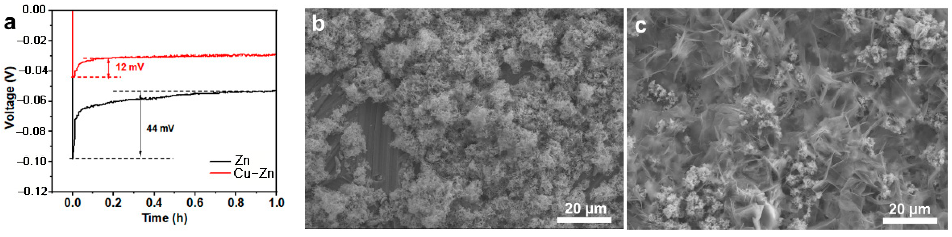
The nucleation overpotential is related to the kinetics of the Zn nucleation and deposition process, and the Zn nucleation consequently determines the quality of Zn deposition [28]. Thus, the Zn nucleation overpotential was measured and compared. As shown in Figure 4a, Cu–Zn showed a lower nucleation potential of 12 mV as compared to 44 mV for Zn, indicating a lower nucleation barrier for Cu–Zn which contributed to a uniform Zn nucleation. To further study the effect of Cu coating on the Zn deposition, the morphology of Cu and Cu–Zn after Zn deposition was characterized (Figure 4b,c). Bare Zn shows a huge amount of Zn microclusters with a porous structure, demonstrating uneven deposition. In contrast, Cu–Zn exhibited a dense and uniform Zn deposit, confirming the beneficial role of the Cu coating.
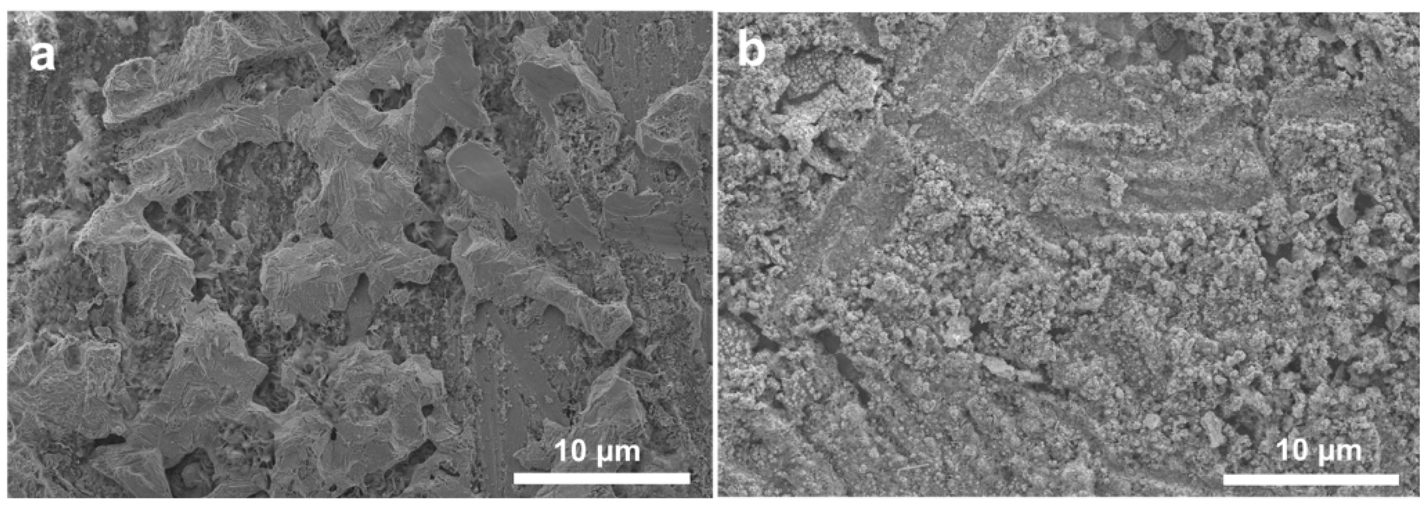
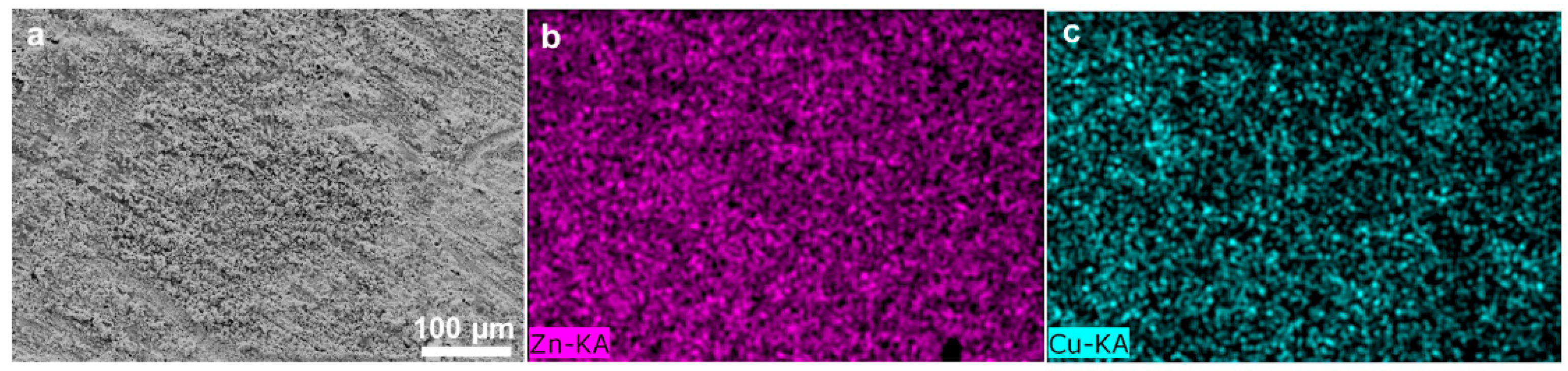
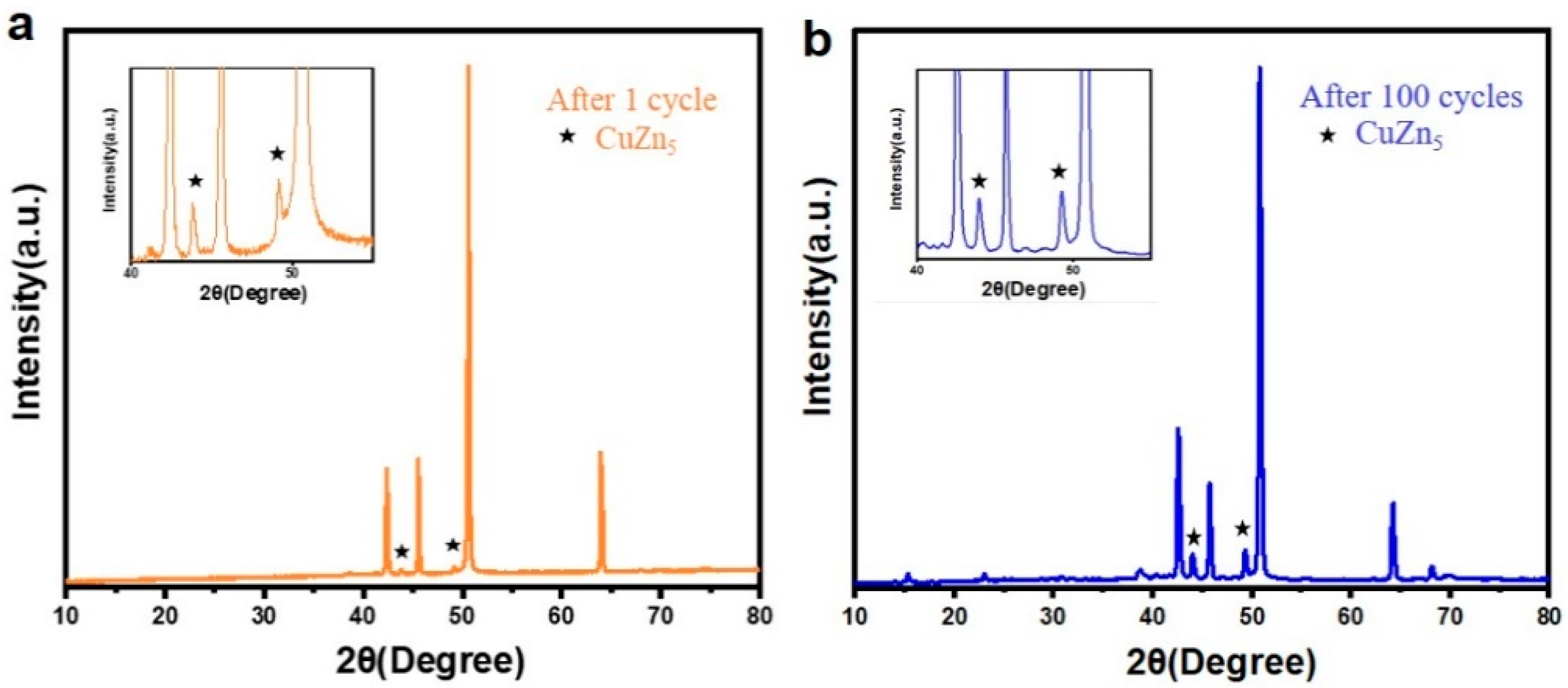
To further investigate the Zn electrodeposition behavior, the morphology of Zn and Cu–Zn electrodes after 30 cycles at a high current density of 5 mA cm−2 was characterized (Figure 5a,b). Bare Zn showed a bulk Zn deposition morphology while Cu–Zn exhibited a uniform and compact morphology. Elemental mapping of Cu–Zn after 50 cycles at a high current density of 5 mA cm−2, confirmed that the uniform distribution of the Cu coating was maintained (Figure 6). It was expected that Cu–Zn alloy was formed during the stripping/plating, due to the negative Gibbs free energy of the reaction [29,30]. In order to check this, a Cu–Zn electrode after 1 cycle was characterized by XRD. As is shown in Figure 7a, two weak peaks at 2θ = 44.1° and 49.5° additionally appeared in the XRD pattern of Cu–Zn after cycling, corresponding to the CuZn5 phase (PDF Number 00-035-1152). The XRD pattern of Cu–Zn after 100 cycles showed that the Cu–Zn alloy was retained, confirming the durability of Cu–Zn alloy during cycling (Figure 7b). The binding energy of Zn-CuZn5 (−1.94 eV) was higher than that of Zn-Cu (−1.58 eV), demonstrating a high Zn affinity of the formed CuZn5 [30]. Thus, the formed alloy could effectively reduce the activation energy of zinc nucleation and the plating resistance of zinc. Consequently, the zinc grew in a smaller size and achieved uniform nucleation without the formation of long and disordered dendrites.
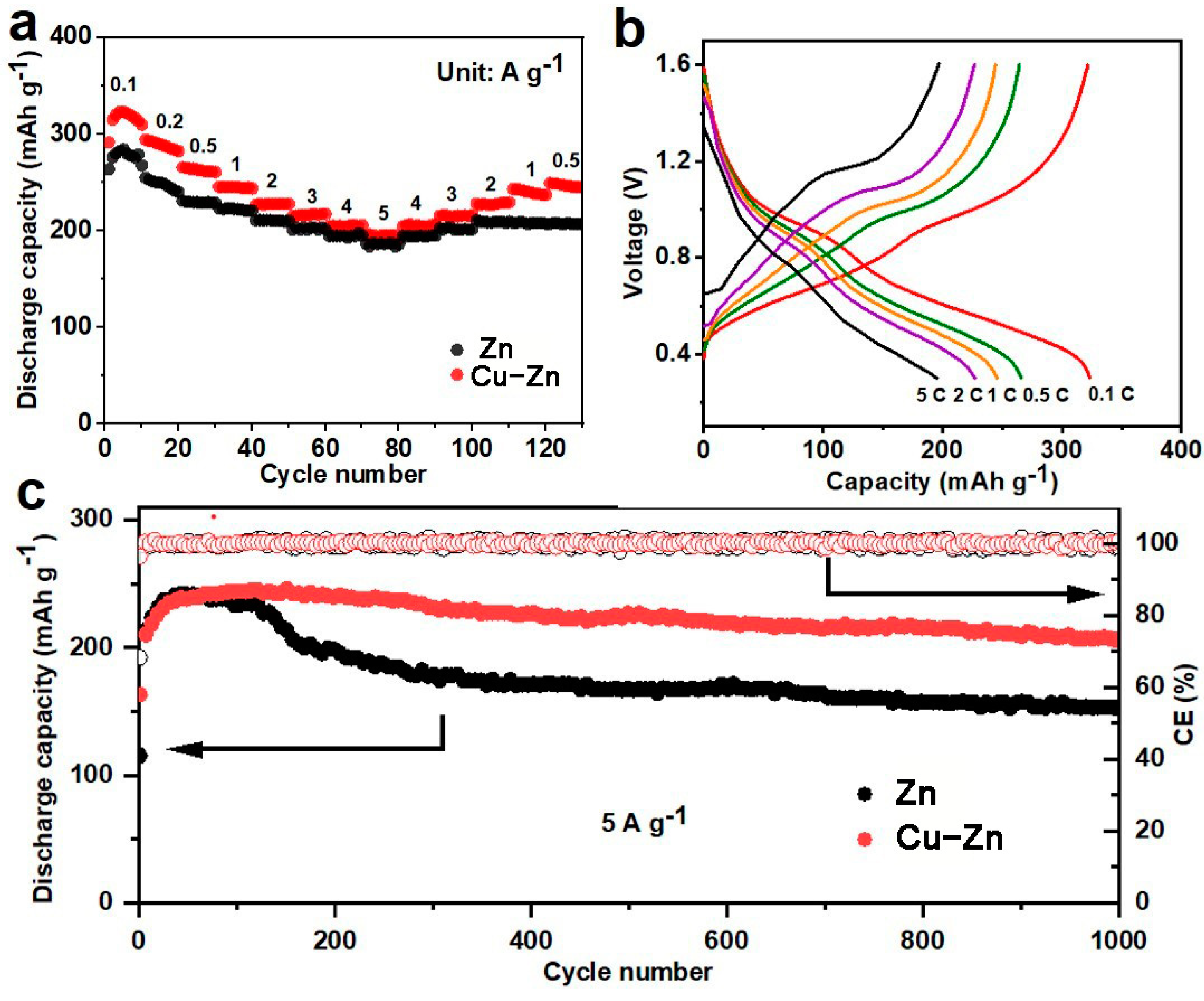
In order to validate the practical application of Cu–Zn, it is necessary to evaluate full cells with cathodes. V2O5-based materials have been used as the cathode for ZIBs due to their high capacity, and V2O5-PEDOT offers improved and stable performance [25,31,32,33,34]. Therefore, V2O5-PEDOT was synthesized based on previously reported work, and full batteries where Zn anodes coupled with V2O5-PEDOT cathodes were assembled and tested (henceforth referred to as V2O5-PEDOT//Zn and V2O5-PEDOT//Cu–Zn, accordingly). The rate performance of the full cells was investigated, as shown in Figure 8a,b. At 0.1, 0.2, 0.5, 1, 2, 3, 4, 5 A∙g−1, V2O5-PEDOT//Cu–Zn cell revealed a high capacity of 323, 311, 266, 246, 227, 215, 205, 195 mAh g−1 respectively, while the V2O5-PEDOT//Zn battery showed a capacity of 284, 255, 231, 223, 211, 201, 194, 187 mAh g−1, respectively. When the current density was set back to 0.5 A∙g−1, the capacity of the V2O5-PEDOT//Zn battery only reached a value of 208 mAh g−1. In contrast, the capacity of the V2O5-PEDOT//Cu–Zn battery recovered significantly to a capacity of 250 mAh g−1, indicating high reversibility. The long-term cycling was also tested at the current density of 5 A∙g−1 (Figure 8c). During the first 60 cycles, both cells showed an enhancement of capacity due to activation. V2O5-PEDOT//Zn underwent a capacity fade after 120 cycles, which was ascribed to the formation of zinc dendrites resulting in “dead Zn” with a subsequent cycling, thereby increasing the internal resistance of the batteries. In sharp contrast, V2O5-PEDOT//Cu–Zn showed a relatively high and stable capacity over 1000 cycles. The stable cycling performance of the full cells with Cu–Zn anodes highlighted the efficiency of Cu in suppressing zinc dendrite and “dead Zn” formation by guiding uniform Zn deposition, and demonstrated high potential for practical applications.
4. Conclusions
In conclusion, we developed a Cu-coated Zn by a straightforward CuSO4 aqueous solution treatment strategy. A CuZn5 alloy was formed after cycling in the battery, which guided the uniform Zn nucleation suppressing the formation of large size Zn dendrites thus improving cycling stability. This strategy not only enabled a remarkable improvement in the cycling life of symmetric cells, but also endowed a high capacity and a stable cycling performance of the full cells coupled with the V2O5-PEDOT cathode. Therefore, coupled with the easy and scalable Zn treatment route, the approach is highly viable for practical implementation in ZIBs. Moreover, this work should open up a promising direction for modifying and protecting other metallic electrodes of rechargeable aqueous battery systems.
Author Contributions
Conceptualization, C.L. and Q.L.; methodology, Q.L.; validation, C.L. and Q.L.; formal analysis, C.L. and Q.L.; investigation, C.L., and Q.L.; data curation, C.L. and Q.L.; visualization, C.L. and Q.L.; writing—original draft preparation, C.L. and Q.L.; writing—review and editing, A.O. and D.M.; supervision, A.O. and D.M.; All authors have read and agreed to the published version of the manuscript.
Funding
Q.L. thanks the financial support from China Scholarship Council (No. 201808080137). The APC was funded by Leibniz Open Access Publishing Fund.
Data Availability Statement
Data is contained within the article.
Acknowledgments
Tianbing He and Xiaoliang Han are acknowledged for help with XRD testing.
Conflicts of Interest
The authors declare no conflict of interest.
References
- Zhang, N.; Chen, X.; Yu, M.; Niu, Z.; Cheng, F.; Chen, J. Materials chemistry for rechargeable zinc-ion batteries. Chem. Soc. Rev. 2020, 49, 4203–4219. [Google Scholar] [CrossRef] [PubMed]
- Lu, Q.; Wang, X.; Cao, J.; Chen, C.; Chen, K.; Zhao, Z.; Niu, Z.; Chen, J. Freestanding carbon fiber cloth/sulfur composites for flexible room-temperature sodium-sulfur batteries. Energy Storage Mater. 2017, 8, 77–84. [Google Scholar] [CrossRef]
- Wu, T.; Zhang, W.; Yang, J.; Lu, Q.; Peng, J.; Zheng, M.; Xu, F.; Liu, Y.; Liang, Y. Architecture engineering of carbonaceous anodes for high-rate potassium-ion batteries. Carbon Energy 2021, 1–28. [Google Scholar] [CrossRef]
- Xu, F.; Zhai, Y.; Zhang, E.; Liu, Q.; Jiang, G.; Xu, X.; Qiu, Y.; Liu, X.; Wang, H.; Kaskel, S. Ultrastable Surface-Dominated Pseudocapacitive Potassium Storage Enabled by Edge-Enriched N-Doped Porous Carbon Nanosheets. Angew. Chem. Int. Ed. 2020, 59, 19460–19467. [Google Scholar] [CrossRef] [PubMed]
- Jiang, G.; Qiu, Y.; Lu, Q.; Zhuang, W.; Xu, X.; Kaskel, S.; Xu, F.; Wang, H. Mesoporous Thin-Wall Molybdenum Nitride for Fast and Stable Na/Li Storage. ACS Appl. Mater. Interfaces 2019, 11, 41188–41195. [Google Scholar] [CrossRef]
- Xu, F.; Ding, B.; Qiu, Y.; Dong, R.; Zhuang, W.; Xu, X.; Han, H.; Yang, J.; Wei, B.; Wang, H.; et al. Generalized Domino-Driven Synthesis of Hollow Hybrid Carbon Spheres with Ultrafine Metal Nitrides/Oxides. Matter 2020, 3, 246–260. [Google Scholar] [CrossRef]
- Lu, Q.; Wang, X.; Omar, A.; Mikhailova, D. 3D Ni/Na metal anode for improved sodium metal batteries. Mater. Lett. 2020, 275, 128206. [Google Scholar] [CrossRef]
- Chao, D.; Zhou, W.; Xie, F.; Ye, C.; Li, H.; Jaroniec, M.; Qiao, S.-Z. Roadmap for advanced aqueous batteries: From design of materials to applications. Sci. Adv. 2020, 6, eaba4098. [Google Scholar] [CrossRef] [PubMed]
- Zhu, M.; Hu, J.; Lu, Q.; Dong, H.; Karnaushenko, D.D.; Becker, C.; Karnaushenko, D.; Li, Y.; Tang, H.; Qu, Z. A Patternable and In Situ Formed Polymeric Zinc Blanket for a Reversible Zinc Anode in a Skin-Mountable Microbattery. Adv. Mater. 2021, 33, 2007497. [Google Scholar] [CrossRef] [PubMed]
- Yao, M.; Yuan, Z.; Li, S.; He, T.; Wang, R.; Yuan, M.; Niu, Z. Scalable Assembly of Flexible Ultrathin All-in-One Zinc-Ion Batteries with Highly Stretchable, Editable, and Customizable Functions. Adv. Mater. 2021, 2008140. [Google Scholar] [CrossRef] [PubMed]
- Wang, X.; Qin, X.; Lu, Q.; Han, M.; Omar, A.; Mikhailova, D. Mixed phase sodium manganese oxide as cathode for enhanced aqueous zinc-ion storage. Chin. J. Chem. Eng. 2020, 28, 2214–2220. [Google Scholar] [CrossRef]
- Zhu, M.; Schmidt, O.G. Tiny robots and sensors need tiny batteries—Here’s how to do it. Nature 2021, 589, 195–197. [Google Scholar] [CrossRef] [PubMed]
- Wan, F.; Zhou, X.; Lu, Y.; Niu, Z.; Chen, J. Energy Storage Chemistry in Aqueous Zinc Metal Batteries. ACS Energy Lett. 2020, 5, 3569–3590. [Google Scholar] [CrossRef]
- Blanc, L.E.; Kundu, D.; Nazar, L.F. Scientific Challenges for the Implementation of Zn-Ion Batteries. Joule 2020, 4, 771–799. [Google Scholar] [CrossRef]
- Tang, B.; Shan, L.; Liang, S.; Zhou, J. Issues and opportunities facing aqueous zinc-ion batteries. Energy Environ. Sci. 2019, 12, 3288–3304. [Google Scholar] [CrossRef]
- Ma, L.; Li, Q.; Ying, Y.; Ma, F.; Chen, S.; Li, Y.; Huang, H.; Zhi, C. Toward Practical High-Areal-Capacity Aqueous Zinc-Metal Batteries: Quantifying Hydrogen Evolution and a Solid-Ion Conductor for Stable Zinc Anodes. Adv. Mater. 2021, 2007406. [Google Scholar] [CrossRef]
- Wang, F.; Borodin, O.; Gao, T.; Fan, X.; Sun, W.; Han, F.; Faraone, A.; Dura, J.A.; Xu, K.; Wang, C. Highly reversible zinc metal anode for aqueous batteries. Nat. Mater. 2018, 17, 543–549. [Google Scholar] [CrossRef]
- Kang, Z.; Wu, C.; Dong, L.; Liu, W.; Mou, J.; Zhang, J.; Chang, Z.; Jiang, B.; Wang, G.; Kang, F. 3D porous copper skeleton supported zinc anode toward high capacity and long cycle life zinc ion batteries. ACS Sustain. Chem. Eng. 2019, 7, 3364–3371. [Google Scholar] [CrossRef]
- Han, D.; Wu, S.; Zhang, S.; Deng, Y.; Cui, C.; Zhang, L.; Long, Y.; Li, H.; Tao, Y.; Weng, Z.; et al. A Corrosion-Resistant and Dendrite-Free Zinc Metal Anode in Aqueous Systems. Small 2020, 16, e2001736. [Google Scholar] [CrossRef]
- Cui, M.; Xiao, Y.; Kang, L.; Du, W.; Gao, Y.; Sun, X.; Zhou, Y.; Li, X.; Li, H.; Jiang, F.; et al. Quasi-Isolated Au Particles as Heterogeneous Seeds to Guide Uniform Zn Deposition for Aqueous Zinc-Ion Batteries. ACS Appl. Energy Mater. 2019, 2, 6490–6496. [Google Scholar] [CrossRef]
- Zhang, Y.; Wang, G.; Yu, F.; Xu, G.; Li, Z.; Zhu, M.; Yue, Z.; Wu, M.; Liu, H.-K.; Dou, S.-X. Highly reversible and dendrite-free Zn electrodeposition enabled by a thin metallic interfacial layer in aqueous batteries. Chem. Eng. J. 2020, 128062. [Google Scholar] [CrossRef]
- Zhang, N.; Huang, S.; Yuan, Z.; Zhu, J.; Zhao, Z.; Niu, Z. Direct Self-Assembly of MXene on Zn Anodes for Dendrite-Free Aqueous Zinc-Ion Batteries. Angew. Chem. Int. Ed. 2020, 60, 2861–2865. [Google Scholar] [CrossRef]
- Zhao, K.; Wang, C.; Yu, Y.; Yan, M.; Wei, Q.; He, P.; Dong, Y.; Zhang, Z.; Wang, X.; Mai, L. Ultrathin surface coating enables stabilized zinc metal anode. Adv. Mater. Interfaces 2018, 5, 1800848. [Google Scholar] [CrossRef]
- Kang, L.; Cui, M.; Jiang, F.; Gao, Y.; Luo, H.; Liu, J.; Liang, W.; Zhi, C. Nanoporous CaCO3 coatings enabled uniform Zn stripping/plating for long-life zinc rechargeable aqueous batteries. Adv. Energy Mater. 2018, 8, 1801090. [Google Scholar] [CrossRef]
- Du, Y.; Wang, X.; Sun, J. Tunable oxygen vacancy concentration in vanadium oxide as mass-produced cathode for aqueous zinc-ion batteries. Nano Res. 2021, 14, 754–761. [Google Scholar] [CrossRef]
- Marcus, P.; Hinnen, C. XPS study of the early stages of deposition of Ni, Cu and Pt on HOPG. Surf. Sci. 1997, 392, 134–142. [Google Scholar] [CrossRef]
- Vogel, Y.B.; Zhang, J.; Darwish, N.; Ciampi, S. Switching of Current Rectification Ratios within a Single Nanocrystal by Facet-Resolved Electrical Wiring. ACS Nano 2018, 12, 8071–8080. [Google Scholar] [CrossRef] [PubMed]
- Pei, A.; Zheng, G.; Shi, F.; Li, Y.; Cui, Y. Nanoscale nucleation and growth of electrodeposited lithium metal. Nano Lett. 2017, 17, 1132–1139. [Google Scholar] [CrossRef]
- Cai, Z.; Ou, Y.; Wang, J.; Xiao, R.; Fu, L.; Yuan, Z.; Zhan, R.; Sun, Y. Chemically resistant Cu–Zn/Zn composite anode for long cycling aqueous batteries. Energy Storage Mater. 2020, 27, 205–211. [Google Scholar] [CrossRef]
- Zhang, Q.; Luan, J.; Fu, L.; Wu, S.; Tang, Y.; Ji, X.; Wang, H. The three-dimensional dendrite-free zinc anode on a copper mesh with a zinc-oriented polyacrylamide electrolyte additive. Angew. Chem. Int. Ed. 2019, 58, 15841–15847. [Google Scholar] [CrossRef]
- Dong, Y.; Jia, M.; Wang, Y.; Xu, J.; Liu, Y.; Jiao, L.; Zhang, N. Long-Life Zinc/Vanadium Pentoxide Battery Enabled by a Concentrated Aqueous ZnSO4 Electrolyte with Proton and Zinc Ion Co-Intercalation. ACS Appl. Energy Mater. 2020, 3, 11183–11192. [Google Scholar] [CrossRef]
- Zhang, N.; Jia, M.; Dong, Y.; Wang, Y.; Xu, J.; Liu, Y.; Jiao, L.; Cheng, F. Hydrated layered vanadium oxide as a highly reversible cathode for rechargeable aqueous zinc batteries. Adv. Funct. Mater. 2019, 29, 1807331. [Google Scholar] [CrossRef]
- Zhang, N.; Dong, Y.; Jia, M.; Bian, X.; Wang, Y.; Qiu, M.; Xu, J.; Liu, Y.; Jiao, L.; Cheng, F. Rechargeable aqueous Zn–V2O5 battery with high energy density and long cycle life. ACS Energy Lett. 2018, 3, 1366–1372. [Google Scholar] [CrossRef]
- Qin, X.; Wang, X.; Sun, J.; Lu, Q.; Omar, A.; Mikhailova, D. Polypyrrole Wrapped V2O5 Nanowires Composite for Advanced Aqueous Zinc-Ion Batteries. Front. Energy Res. 2020, 8, 199. [Google Scholar] [CrossRef]
Figure 1.
SEM images and optical images (insets) of (a) bare Zn foil and (b) Cu–Zn foil, (c) cross-section SEM images of Cu–Zn foil, (d) high resolution Cu 2p XP spectrum measured on Cu–Zn foil.
Figure 1.
SEM images and optical images (insets) of (a) bare Zn foil and (b) Cu–Zn foil, (c) cross-section SEM images of Cu–Zn foil, (d) high resolution Cu 2p XP spectrum measured on Cu–Zn foil.

Figure 2.
(a) SEM image and (b,c) the corresponding elemental mappings of Cu–Zn.

Figure 3.
Long-term galvanostatic discharge/charge profiles of symmetric cells with bare Zn and Cu–Zn at current density of (a) 0.2 mA cm−2, (b) 0.5 mA cm−2, and (c) 1 mA cm−2.
Figure 3.
Long-term galvanostatic discharge/charge profiles of symmetric cells with bare Zn and Cu–Zn at current density of (a) 0.2 mA cm−2, (b) 0.5 mA cm−2, and (c) 1 mA cm−2.

Figure 4.
(a) The voltage-time curves during Zn nucleation and deposition on Zn and Cu–Zn at 1 mA cm−2, SEM images of (b) Zn and (c) Cu–Zn after Zn-depositing with a capacity of 2 mAh cm−2 at current density of 1 mA cm−2.
Figure 4.
(a) The voltage-time curves during Zn nucleation and deposition on Zn and Cu–Zn at 1 mA cm−2, SEM images of (b) Zn and (c) Cu–Zn after Zn-depositing with a capacity of 2 mAh cm−2 at current density of 1 mA cm−2.

Figure 5.
SEM images of (a) Zn and (b) Cu–Zn after 30 cycles at a current density of 5 mA cm−2 with a capacity of 1 mAh cm−2.
Figure 5.
SEM images of (a) Zn and (b) Cu–Zn after 30 cycles at a current density of 5 mA cm−2 with a capacity of 1 mAh cm−2.

Figure 6.
(a) SEM image and (b,c) corresponding elemental mappings of Cu–Zn after 50 cycles at current density of 5 mA cm−2 with a capacity of 1 mAh cm−2.
Figure 6.
(a) SEM image and (b,c) corresponding elemental mappings of Cu–Zn after 50 cycles at current density of 5 mA cm−2 with a capacity of 1 mAh cm−2.

Figure 7.
XRD pattern of Cu–Zn (a) after 1 cycle and (b) after 100 cycles at current density of 5 mA cm−2 with a capacity of 1 mAh cm−2. ★ represents the XRD peak of CuZn5.
Figure 7.
XRD pattern of Cu–Zn (a) after 1 cycle and (b) after 100 cycles at current density of 5 mA cm−2 with a capacity of 1 mAh cm−2. ★ represents the XRD peak of CuZn5.

Figure 8.
(a) Rate performance of V2O5-PEDOT//Zn and V2O5-PEDOT//Cu-Zn, (b) charge/discharge curves of V2O5-PEDOT//Cu–Zn at different current densities, (c) cycling performance of V2O5-PEDOT//Zn and V2O5-PEDOT//Cu–Zn at a current density of 5 A∙g−1.
Figure 8.
(a) Rate performance of V2O5-PEDOT//Zn and V2O5-PEDOT//Cu-Zn, (b) charge/discharge curves of V2O5-PEDOT//Cu–Zn at different current densities, (c) cycling performance of V2O5-PEDOT//Zn and V2O5-PEDOT//Cu–Zn at a current density of 5 A∙g−1.


Table 1.
Comparison of the performance of Cu–Zn symmetric cells with recent literature on various Zn surface modification strategies.
Table 1.
Comparison of the performance of Cu–Zn symmetric cells with recent literature on various Zn surface modification strategies.
| Protective Layers | Current Density (mA cm−2) | Capacity (mAh cm−2) | Life (h) | Reference |
|---|---|---|---|---|
| 0.2 | 0.2 | 1600 | ||
| Cu coating | 0.5 | 0.5 | 600 | This work |
| 1 | 1 | 290 | ||
| In coating | 0.2 | 0.2 | 1500 | [19] |
| Au coating | 0.25 | 0.05 | 2000 | [17] |
| MXene | 0.2 | 0.2 | 800 | [22] |
| CaCO3 coating | 0.25 | 0.05 | 840 | [24] |
| TiO2 coating | 1 | 1 | 150 | [23] |
Publisher’s Note: MDPI stays neutral with regard to jurisdictional claims in published maps and institutional affiliations. |
© 2021 by the authors. Licensee MDPI, Basel, Switzerland. This article is an open access article distributed under the terms and conditions of the Creative Commons Attribution (CC BY) license (http://creativecommons.org/licenses/by/4.0/).
Share and Cite
MDPI and ACS Style
Liu, C.; Lu, Q.; Omar, A.; Mikhailova, D. A Facile Chemical Method Enabling Uniform Zn Deposition for Improved Aqueous Zn-Ion Batteries. Nanomaterials 2021, 11, 764. https://0-doi-org.brum.beds.ac.uk/10.3390/nano11030764
AMA Style
Liu C, Lu Q, Omar A, Mikhailova D. A Facile Chemical Method Enabling Uniform Zn Deposition for Improved Aqueous Zn-Ion Batteries. Nanomaterials. 2021; 11(3):764. https://0-doi-org.brum.beds.ac.uk/10.3390/nano11030764
Chicago/Turabian StyleLiu, Congcong, Qiongqiong Lu, Ahmad Omar, and Daria Mikhailova. 2021. "A Facile Chemical Method Enabling Uniform Zn Deposition for Improved Aqueous Zn-Ion Batteries" Nanomaterials 11, no. 3: 764. https://0-doi-org.brum.beds.ac.uk/10.3390/nano11030764
Note that from the first issue of 2016, this journal uses article numbers instead of page numbers. See further details here.