
Investigating Tungsten Sulfide as a Counter Electrode Material in Dye-Sensitized Solar Cells


Department of Mechanical Engineering, Wichita State University, 1845 Fairmount St, Wichita, KS 67260, USA
*
Author to whom correspondence should be addressed.
Nanomaterials 2022, 12(16), 2761; https://0-doi-org.brum.beds.ac.uk/10.3390/nano12162761
Submission received: 27 July 2022
/
Revised: 8 August 2022
/
Accepted: 10 August 2022
/
Published: 12 August 2022
(This article belongs to the Special Issue Advances in Nanotechnology of Perovskite and Silicon Solar Cells)
Abstract
:With the recent interest in renewable energy sources, dye-sensitized solar cells (DSSCs) have received a great deal of attention as a cheaper and more sustainable alternative to silicon-based solar cells. In a DSSC, the counter electrode performs the catalytic reduction of the electrolyte and electron collection. To perform this function adequately, platinum is the preferred material currently. To reduce the dependence of the DSSC on such an expensive material, alternatives such as activated carbon (AC) and two-dimensional transition metal dichalcogenides, and more specifically, tungsten sulfide (WS2), were considered. AC has shown great potential as a material for counter electrodes, whereas WS2 has unique physiochemical properties which warrant its exploration as an energy material. In this article, we synthesized and evaluated the performance of DSSCs with AC, WS2, and AC/WS2 composite counter electrodes. It was demonstrated that the performance of the WS2/AC composite counter electrode with a 1:2 ratio of WS2 to AC shows the highest performance with an efficiency of 6.25%.
1. Introduction
The global demand for energy over the years poses a significant challenge to future generations if there is no diversification of energy sources [1]. Energy demand is dramatically increasing while there is a lack of energy resources to replace fossil fuels, and there is already a reduction in oil assets extant on the crust of the earth [2]. The continued use of these fossil fuels will lead to a negative impact on the environment and living species, and lead to the destruction of ecosystems, impacting the human population [3]. In order to address these problems, the scientific community has shown a great tendency to study renewable energy resources, which are compatible with today’s environmental policy. Solar energy has a large energy reservoir and easy availability, which puts it at the forefront of renewable energy sources [4]. Thus, to optimize energy management and improve environmental security, it is vital to utilize the solar spectrum to generate power through the application of photovoltaic devices, which are capable of producing electricity directly from sunlight without any moving mechanical components. Because of the technological maturity and high efficiency, silicon-based solar devices are enjoying a major share in the overall market [5,6]. Silicon-based solar devices have a complicated production process and require many rare earth metals for the doping of silicon. These two factors increase the cost of this technology for urban and other commercial applications, limiting their deployment [7].
The dye-sensitized solar cell (DSSC) is a third-generation solar cell, which is a promising alternative to conventional silicon solar cells in terms of optimum efficiency and ease of manufacture [8,9,10]. In addition to those advantages, they are lightweight, flexible, and have a low cost per unit [11]. The DSSC consists of five important components, i.e., the substrate (conductive substrate or conductive film-coated substrate), semiconductor nanostructure (photoanode), sensitizer (dye), electrolyte, and catalyst-coated counter electrode [12]. To measure the performance of a solar cell, the efficiency and the fill factor of the device are considered. The fill factor determines the maximum power of the cell with respect to the open-circuit voltage and the short-circuit current. To generate usable electrical energy from sunlight, the DSSC presents three steps: (1) photoexcitation of dyes by transferring an electron to the conduction band of the semiconductor (in this case TiO2); (2) regeneration of the oxidized dye molecules with electron donation from the redox couple present in the electrolyte; and (3) migration of the electron through the external load to complete the circuit [13,14]. The entire operation takes place with the help of all the components of the DSSC [15,16]. The collection of electrons from the external load is performed by the counter electrode (CE), which also catalyzes the reduction of I3− to I−, thereby realizing the regeneration of the sensitizer. The most commonly used CE is platinum (Pt), which is deposited on the fluorine-doped tin oxide (FTO) conductive glass. However, the high cost of Pt has reduced the commercialization of DSSCs. Transition metal dichalcogenides (TMDs) have been established to have good electrical and thermal conductivity, along with the durability of the covalent bond and high melting temperature. The investigation of graphene-like layered metal dichalcogenides is still in its early stages. Tungsten dichalcogenides, which are the same as other TMDs, offer active sites for catalytic reactions [17,18]. Based on recent studies, the performance of conventional Pt counter electrodes in DSSC devices can be surpassed when Pt is replaced by TMDs [9,19]. Replacing platinum counter electrodes to develop low-cost, catalytically active, and stable counter electrodes by utilizing WS2 is one of the hot topics among researchers nowadays [20,21,22,23]. In addition to TMDs, carbon-based materials are proven to increase efficiency and reduce the cost of DSSCs [10].
To use WS2 as a counter electrode in DSSCs, thin films of the material are usually prepared and layered on a conductive FTO glass. This can be achieved using doctor blading as demonstrated by Li et al. [24]. The thin films of WS2 show promising results, but suffer in comparison to other materials due to relatively worse conductivity [25]. To counter this, Wang et al. made a multilayer CE with a layer of activated carbon (AC) on top of the WS2 layer [26]. Although they could not observe a chemical bonding between carbon and WS2 nanoparticles after the coating process, the presence of the amorphous layer of carbon increases the conductivity between WS2 particles. The power conversion efficiency (PCE) of the carbon-coated WS2 counter electrode was 5.5%, which is comparable to that of the Pt counter electrode (5.6%). A novel WS2/carbon film was developed by Shen et al. for use as a counter electrode after the sulfurization of a mesoporous WOx/carbon film [27]. The continuous carbon layer provides a facile electron transfer and electrolyte diffusion to the 3D WS2 framework, contributing high electrocatalytic activity and fast reaction kinetics for the redox of I3−/I−. The power conversion rate of 7.71% was reported for this WOx@WS2@carbon composite counter electrode, which is favorably comparable to that of the WOx/carbon CE (6.00%) and conventional Pt counter electrode (7.34%). Finally, it was reported that the PCEs were 7.25% and 4.67% for WO2 CE and WO3 CE, respectively [28]. It is theorized that the carrier concentration increases from WO3 to WO2 as the coordination number of the anion decreases, leading to a higher charge transfer rate [29]. These findings allow us to assume there is an optimum amount of carbon that would enhance the performance of the CE to the highest levels possible in this device. However, care must be taken as a rich carbon coating can cover the active sites of WS2, which decreases the overall bonding strength.
In this report, we synthesized the WS2/activated carbon composites as counter electrode materials for DSSCs and explored the impact of the composition of the composite materials.
2. Experimental Methods
2.1. Preparation of Photoelectrode
Titanium oxide (TiO2) powder was purchased from Sigma-Aldrich (Sigma Aldrich inc., St. Louis, MO, USA) and used as received. The photoelectrodes were prepared by mixing 0.1 g of TiO2 powder in 1 mL of ethanol. Then, the paste was applied to a fluorine-doped tin oxide (FTO) surface by the doctor-blading method to prepare films with a dimension of 0.5 cm by 0.5 cm, leading to an overall surface of 0.25 cm2. The process was followed by sintering at 500 °C for 40 min. After the samples cooled down, a dye bath was prepared by mixing 0.0042 g of N719 in 20 mL of ethanol, and photoelectrodes were placed into the dye for 72 h. Powder X-ray diffraction measurements of electrode materials were performed to determine their crystal structure by using a Rigaku MiniFlex II X-ray diffractometer (Rigaku, Austin, TX, USA).
2.2. Preparation of Counter Electrode
The tungsten sulfide (WS2) was purchased from Alfa Aesar (Alfa Aesar, Tewksbury, MA, USA) and used without any chemical modification. To establish the performance of the materials, a batch of counter electrodes was made with pure WS2. To prepare the thin film, 0.6 g of WS2 was suspended in 1 mL of ethanol to form a paste for uniform distribution. The resultant paste of this mixture was hand-ground for 30 min to achieve a finer and more uniform paste. The paste was doctor-bladed on the FTO glass substrate. The film was then placed in an oven at 65 °C for 2 h to eliminate the moisture. The fabrication of the WS2/AC CEs was the same as described above by varying ratios of AC vs. WS2. Platinized CEs were fabricated by dropping a platinum precursor (chloroplatinic acid hexahydrate) on a cleaned FTO glass substrate and sintering it at 500 °C for 40 min. A scanning electron microscope (Phenom Pharos system, Nanoscience Instruments, Phoenix, AZ, USA) was employed to characterize the morphologies of electrode materials. This device uses a Schottky field emitter as the source and has a maximum magnification of 1,000,000×. The resolution of the equipment was 2.5 nm at 15 kV (SED), 4 nm at 15 kV (BSD), and 10 nm at 3 kV.
2.3. Preparation of Electrolyte
The electrolyte for the DSSC was made by mixing 0.100 g of I2, 0.034 g of LiI, 0.318 g of tert-butylpyridine, 1.600 g of 1-buty-3-methylimidazolium, and 0.600 g of guanidine thiocyanate into 10 mL of solvent: 8.5 mL of ethanol and 1.5 mL of valeronitrile. The electrolyte for CV measurement was made by adding 0.134 g of LiI to 1.066 g of LiClO4 and 0.027 g of I2 and dissolving the mixture in 100 mL of acetonitrile. All materials for the electrolytes were purchased from Sigma-Aldrich (Sigma Aldrich Inc., St. Louis, MO, USA) and used as received.
2.4. Fabrication and Evaluation of DSSCs
The DSSCs were fabricated by layering the dye-immersed TiO2 photoelectrodes facing the active area of the counter electrodes. The prepared electrolyte solution was filled in between the electrodes before they were attached. The I-V characterization was performed with the Gamry Interface 5000e (Gamry Instruments, Warminster, PA, USA) equipment. The scanning rate was 10 mV s−1 with a step size of 10 mV. The ORIEL LED Solar Simulator was used to simulate sunlight at an intensity of 100 mW cm−2. For the cyclic voltammetry measurement, the three-electrode method along with the Gamry Interface 5000e (Gamry Instruments, Warminster, PA, USA) equipment was used. The three electrodes consisted of a reference electrode of Ag/AgCl, a counter electrode of Pt, and the working electrode, which is the electrode under investigation. The scan rate of 20 mV s−1 was used with a step size of 20 mV. The electrochemical impedance spectroscopy (EIS) characterization was carried out with the Gamry Interface 5000e (Gamry Instruments, Warminster, PA, USA) with scanning frequencies between 100 kHz and 10 MHz at open-circuit voltage.
3. Results and Discussions
In order to investigate the morphologies of counter electrodes in DSSCs, the scanning electron microscope (SEM) was employed and the obtained SEM images are shown in Figure 1. The WS2 flakes can be observed in Figure 1a; they are very thin but in all different sizes. The surface of the WS2 flakes looks very smooth in most areas. On the other hand, the AC has a very porous structure while the particles are bulkier in comparison with WS2, as shown in Figure 1b. Differences in the structures of these two powders must lead to an interesting structure. Figure 1c illustrates the SEM image of WS2/AC composites with a ratio of 1:2. The smaller particles of AC are placed on the surface of the WS2 flakes and, therefore, increase the free space in the structure. Based on the SEM observations, it is notable that mixing WS2 with AC was successfully placed and good uniformity of the structure is detected in various areas of the composite.
In the literature, the porosity of AC and WS2 was reported as 720 m2/g and 3.49 m2/g, respectively. Thus, the total porosity of WS2/AC (1:2) is expected to be more than that of AC and WS2 separately. Therefore, theoretically, a higher surface area should be accessible. Hence, the catalytic activity of the composite is expected to be higher than that of both WS2 and AC. Another advantage of the porous structure of the composite is that there would be a better surface connection between the counter electrode and the electrolyte. In other words, a better connection on the surface between the CE and electrolyte means a better charge transfer ability for electrons. Consequently, the charge transfer resistance of the WS2/AC (1:2) composite is expected to be lower than that of AC, which is later confirmed by the electrochemical impedance spectrum (EIS) results.
The crystal structures of electrode materials were further evaluated by X-ray powder diffraction (XRD) using the Rigaku MiniFlex II X-ray diffractometer. The comparison between the XRD results of WS2, AC, and WS2/AC (1:2) is illustrated in Figure 2. Since the highest recorded peak intensity of WS2 is much larger than that of AC, the correlated peak of AC is not significant. The peak intensity of the WS2/AC composition decreases in comparison with the peaks of pure WS2. The reason is that the AC powder has a much smaller particle size in comparison with the WS powder. Hence, the composition has a smaller particle size in comparison to that of pure WS2. The average particle sizes of the WS2, activated carbon, and composite mixture are found to be 29.68 nm, 0.96 nm, and 22.46 nm, respectively.
As shown in Figure 2, the highest intensity is observed at 14°, which is related to the (002) plane. The other two peaks with the highest intensity values could be found at 27° and 43° corresponding to the (004) and (006) planes, respectively. The XRD pattern of the AC has a very wide peak that is observed in a range from 16° to 30°. The maximum intensity of this peak is observed at 21° while another peak can be found at 43°. The XRD pattern of the WS2/AC (1:2) shows a similar pattern with pure WS2. However, due to the presence of AC, there is a wide and low-intensity peak from 16° to 30°. All other high-intensity peaks are attributed to the presence of WS2.
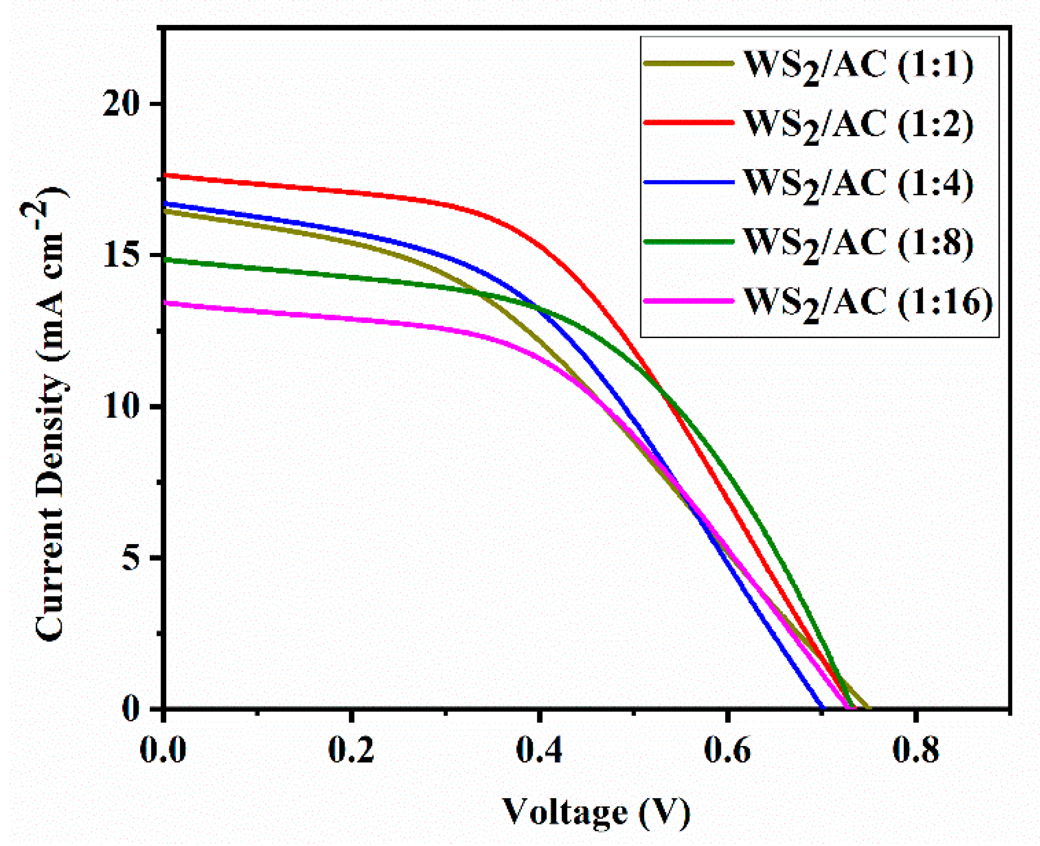
To investigate the performance of WS2/AC composite materials as counter electrodes in DSSCs, the I-V measurements were carried out. The results of I-V measurements for different ratios of WS2/AC composites are illustrated in Figure 3. The highest and the lowest short circuit current (ISC) are obtained at the ratio of 1:2 (17.65 mAcm−2) and 1:16 (13.11 mA cm−2), respectively. However, the open-circuit voltage (VOC) is almost the same for most of the DSSCs, ranging between 0.70 V to 0.75 V. Moreover, the WS2/AC composite with the ratio 1:2 has the most rectangular shape (higher fill factor) in comparison with the other ratios. In other words, the performance (6.25%) of composite material-based DSSCs would be the best when the ratio of 1:2 is used. Hence, we compared the result of WS2/AC (1:2) with WS2- and AC-based DSSCs to obtain a better understanding of performance improvement.
Figure 4 shows the I-V curves of DSCCs with WS2, AC, and WS2/AC composites as counter electrodes. The WS2-based DSSC has very small values for both ISC and VOC, suggesting that its performance is very poor. Although the AC-based DSSC shows a slightly higher VOC than the WS2/AC (1:2) composite-based DSSC, there is a significant difference between the ISC for these two different devices.
The parameters, such as FF and η, are then calculated from the graph. The parameters and photovoltaic performance of the prepared cells are shown in Table 1. However, the η of a DSSC does not comprise the amount of light captivated by the dye but measures the overall conversion of applied light to electrical power. The η of the DSSC was obtained by calculating the ratio of the maximum power generated by the device to the intensity of the incident light from the solar simulator on the active area of the device. The WS2/AC composite cell with the ratio 1:2 achieved the best efficiency, as high as 6.25%, which is significantly higher than that of WS2- and AC-based cells at 1.79% and 4.50%, respectively. It is of great importance that all the cells made of the WS2/AC composite have shown a better performance than both WS2- and AC-based cells. In addition, the FF values are in a range between 0.39 and 0.52. Furthermore, the Pt-based DSSC was also fabricated as a comparison. As shown in Table 1, the WS2/AC-based DSSC shows higher efficiency (6.25%) than that of the Pt-based device (4.5%).
Based on a simple comparison of the open-circuit voltage amount of WS2 samples and WS2/AC (1:2) samples from Table 1, we found a decrease in the VOC for CEs made of the WS2/AC composite. Although the VOC corresponds to the energy difference between the Fermi level of the semiconductor and the redox energy level of the redox couple theoretically, the decrease in the value of the VOC is due to the over potential at the counter electrode in practice [30]. The increase in the amount of AC composition of the CE could explain the change in VOC values.
It is of great importance to mention that the short-circuit current is identical to the light-generated current. In other words, ISC is similar to the generation and collection of light-generated carriers, and therefore, it is the largest current that could be drawn from the DSSC. There are several parameters that could have an influence on the ISC including the area of the solar cell, the number of photons (known as the power of the incident light source), the optical properties, and the collection probability of the solar cell. The surface area and the incident light power are the same for all the DSSCs and could not play a role in the observed ISC difference. Hence, the difference in ISC is believed to be caused by a difference in the diffusion length that could be varied based on the absorption and reflection of the solar cell, as well as the surface passivation.
Cyclic voltammetry was used to examine the active surface area of the prepared cells. The reduction–oxidation abilities of the WS2-, AC-, and WS2/AC-based CEs on the I−/I3− redox couple were studied at a scan rate of 20 mV s−1 and step size of 20 mV at room temperature. The CV measurements were performed between −0.4 and 0.6 V using a three-electrode configuration. As the CV results can be seen in Figure 5 the WS2 curve indicates an almost linear behavior where the very low area of the loop suggests that the electric property of this cell is very poor. Both AC and WS2/AC cells show a much higher loop surface compared with WS2; however, the WS2/AC composite cell has a smaller peak-to-peak separation (Epp = 0.32 V). Although the Epp of the composite CE is almost equal to that of the AC, the composite CE has a current density of 2.19 mA cm−2 which is higher than that of WS2- and AC-based cells. The obtained results illustrate that the WS2/AC composite can increase the catalytic activity of the WS2- and AC-based DSSCs as theorized when looking at the SEM imaging.
To have a better understanding of the electrical behavior of the cells, such as charge transport, transfer, and accumulation processes in the cell, the EIS measurement was used via the two-electrode method. A typical EIS spectrum of a DSSC illustrates information about charge transport as a result of electron diffusion through the photoelectrode (TiO2) and ionic diffusion in the electrolyte solution. In addition, the EIS spectrum indicates charge transfer attributable to the electron back reaction at the FTO/electrolyte interface, recombination at the TiO2/electrolyte interface, and regeneration of the redox species at CE/electrolyte interfaces.
The Nyquist plot of the WS2, AC, and WS2/AC (1:2) cells at different potentials is shown in Figure 6. As can be seen, the charge transfer resistance at the interface between the CE and electrolyte is much lower for the WS2/AC composite cell in comparison with AC and WS2 cells. Although the second minimum point is not observed for any of the cells, by extrapolating the plots, it can be explained that the charge transfer resistance between the photoelectrode and electrolyte shows a similar change seen in the CE/electrolyte interface, which indicates that the addition of the WS2 reduces the resistance between the interface.
4. Conclusions
The use of tungsten dichalcogenides, and more specifically, that of WS2 with activated carbon, as a CE material shows better catalytic activity due to increased porosity, leading to a better performance compared to pure WS2. The WS2/AC composite counter electrode indicates a smaller peak-to-peak gap and a higher current density than that of WS2 or AC CEs, proving this composite CE has a better catalytic activity in comparison with pure WS2- and pure AC CE-based DSSCs. Moreover, the charge transfer resistance in both interfaces between the CE/electrolyte and PE/electrolyte is much smaller than that of pure WS2- and pure AC CE-based DSSCs. This result from the EIS measurement illustrates the better conductivity of the WS2/AC composite CEs, leading to a better performance of DSSCs. The constructed composite DSSC with the ratio of 1:2 between WS2 and AC exhibited a high-power conversion efficiency of 6.25%, which is much higher than that of WS2 (1.79%) and AC (4.50%)-based DSSCs. This novel WS2/AC-based DSSC opens up opportunities for a variety of optoelectronic and photoelectrochemical applications.
Author Contributions
Conceptualization, W.W.; investigation, S.C.M. and S.R.; data curation, S.C.M. and S.R.; writing—original draft preparation, S.C.M. and S.R.; writing—review and editing, W.W.; supervision, W.W.; funding acquisition, W.W. All authors have read and agreed to the published version of the manuscript.
Funding
This work was partially supported by the Kansas National Science Foundation EPSCoR Research Infrastructure Improvement Program Track-1:(RII Track-1): OIA-1656006 and start-up funds from Wichita State University.
Data Availability Statement
Data can be available upon request from the authors.
Acknowledgments
The authors acknowledge the funding support from National Science Foundation and Wichita State University.
Conflicts of Interest
The authors declare no conflict of interest.
References
- Smalley, R.E. Future Global Energy Prosperity: The Terawatt Challenge. MRS Bull. 2005, 30, 412–417. [Google Scholar] [CrossRef]
- Bahnemann, D. Photocatalytic water treatment: Solar energy applications. Sol. Energy 2004, 77, 445–459. [Google Scholar] [CrossRef]
- Grossman, G.M.; Krueger, A.B. Economic growth and the environment. Q. J. Econ. 1995, 110, 353–377. [Google Scholar] [CrossRef]
- Olsthoorn, D.; Haghighat, F.; Mirzaei, P. Integration of storage and renewable energy into district heating systems: A review of modelling and optimination. Sol. Energy 2016, 136, 49–64. [Google Scholar] [CrossRef]
- Pandey, A.; Tyagi, V.; Selvaraj, J.A.; Rahim, N.; Tyagi, S. Recent advances in solar photovoltaic systems for emerging trends and advanced applications. Renew. Sustain. Energy Rev. 2016, 53, 859–884. [Google Scholar] [CrossRef]
- Green, M.A.; Emery, K.; Hishikawa, Y.; Warta, W.; Dunlop, E.D. Solar cell efficiency tables (version 48). Prog. Photovolt. Res. Appl. 2016, 7, 905–913. [Google Scholar] [CrossRef]
- O’Regan, B.; Gratzel, M. A low-cost, high-efficiency solar cell based on dye-sensitized colloidal TiO2 films. Nature 1991, 353, 737–740. [Google Scholar] [CrossRef]
- Chauhan, A.; Saini, R. A review on integrated renewable energy system based power generation for stand-along applications: Configurations, storage options, sizing methodologies and control. Renew. Sustain. Energy Rev. 2014, 38, 99–120. [Google Scholar] [CrossRef]
- Rashidi, S.; Caringula, A.; Nguyen, A.; Obi, I.; Obi, C.; Wei, W. Recent progress in MoS2 for solar energy conversion applications. Front. Energy 2019, 13, 251–268. [Google Scholar] [CrossRef]
- Patil, K.; Rashidi, S.; Wang, H.; Wei, W. Recent Progress of Graphene-Based Photoelectrode Materials for Dye-Sensitized Solar Cells. Int. J. Photoenergy 2019, 2019, 16. [Google Scholar] [CrossRef]
- Green, M.A. Thin-film solar cells: Review of materials, technologies and commercial status. J. Mater. Sci. Mater. Electron. 2007, 18, 15–19. [Google Scholar] [CrossRef]
- Ahmad, M.S.; Pandey, A.; Rahim, N.A. Advancements in the development of TiO2 photoanodes and its fabrication methods for dye sensitized solar cell (DSSC) applications: A review. Renew. Sustain. Energy Rev. 2017, 77, 89–108. [Google Scholar] [CrossRef]
- Ganesan, S.; Muthuraaman, B.; Mathew, V.; Madhavan, J.; Maruthamuthu, P.; Suthanthiraraj, S.A. Performance of a new polymer electrolyte incorporated with diphenylamine in nanocrystalline dye-sensitized solar cell. Sol. Energy Mater. Sol. Cells 2008, 92, 1718–1722. [Google Scholar] [CrossRef]
- Ragoussi, M.-E.; Ince, M.; Torres, T. Recent Advances in Phthalocyanine-Based Sensitizers for Dye-Sensitized Solar Cells. Eur. J. Org. Chem. 2013, 2013, 6475–6489. [Google Scholar] [CrossRef]
- Zhang, Z.; Yates, J.T., Jr. Direct observation of surface-mediated electron−hole pair recombination in TiO2 (110). J. Phys. Chem. C 2010, 114, 3098–3101. [Google Scholar] [CrossRef]
- Raghavan, N.; Thangavel, S.; Venugopal, G. Enhanced photocatalytic degradation of methylene blue by reduced graphene-oxide/titanium dioxide/zinc oxide ternary nanocomposites. Mater. Sci. Semicond. Processing 2015, 30, 321–329. [Google Scholar] [CrossRef]
- Pashigreva, A.V.; Kondratieva, E.; Bermejo-Deval, R.; Gutiérrez, O.Y.; Lercher, J.A. Methanol thiolation over Al2O3 and WS2 catalysts modified with cesium. J. Catal. 2017, 345, 308–318. [Google Scholar] [CrossRef]
- dos Santos, V.C.; Durndell, L.J.; Isaacs, M.A.; Parlett, C.M.; Wilson, K.; Lee, A.F. A new application for transition metal chalcogenides: WS2 catalysed esterification of carboxylic acids. Catal. Commun. 2016, 91, 16–20. [Google Scholar] [CrossRef]
- Rashidi, S.; Rashidi, S.; Heydari, R.; Esmaeili, S.; Tran, N.; Thangi, D.; Wei, W. WS2 and MoS2 counter electrode materials for dye-sensitized solar cells. Prog. Photovolt. Res. Appl. 2021, 29, 238–261. [Google Scholar] [CrossRef]
- Wu, M.; Wang, Y.; Lin, X.; Yu, N.; Wang, L.; Wang, L.; Hagfeldt, A.; Ma, T. Economical and effective sulfide catalysts for dye-sensitized solar cells as counter electrodes. Phys. Chem. Chem. Phys. 2011, 13, 19298–19301. [Google Scholar] [CrossRef]
- Wang, M.; Chamberland, N.; Breau, L.; Moser, J.-E.; Humphry-Baker, R.; Marsan, B.; Zakeeruddin, S.M.; Grätzel, M. An organic redox electrolyte to rival triiodide/iodide in dye-sensitized solar cells. Nat. Chem. 2010, 2, 385–389. [Google Scholar] [CrossRef] [PubMed]
- Hussain, S.; Shaikh, S.; Vikraman, D.; Mane, R.; Joo, O.; Naushad, M.; Jung, J. Sputtering and sulfurization-combined synthesis of a transparent WS2 counter electrode and its application to dye-sensitized solar cells. RSC Adv. 2015, 5, 103567–103572. [Google Scholar] [CrossRef]
- Tan, C.; Zhao, W.; Chaturvedi, A.; Fei, Z.; Zeng, Z.; Chen, J.; Huang, Y.; Ercius, P.; Luo, Z.; Qi, X.; et al. Preparation of single-layer MoS2xSe2 (1-x) and MoxW1-xS2 nanosheets with high-concentration metallic 1T phase. Small 2016, 12, 1866–1874. [Google Scholar] [CrossRef]
- Li, S.; Chen, Z.; Zhang, W. Dye-sensitized solar cells based on WS2 counter electrodes. Mater. Lett. 2011, 72, 22–24. [Google Scholar] [CrossRef]
- Vikraman, D.; Hussain, S.; Patil, S.; Truong, L.; Arbab, A.; Heong, S.; Chun, S.; Jung, J.; Kim, H. Engineering MoSe2/WS2 hybrids to replace the scarce platinum electrode for hydrogen evolution reactions and dye-sensitized solar cells. ACS Appl. Mater. Interfaces 2021, 13, 5061–5072. [Google Scholar] [CrossRef] [PubMed]
- YWang, Y.; Li, S.; Bai, Y.; Chen, Z.; Jiang, Q.; Li, T.; Zhang, W. Dye-sensitized solar cells based on low cost carbon-coated tungsten disulphide counter electrodes. Electrochim. Acta 2013, 114, 30–34. [Google Scholar]
- Shen, Z.; Wang, M.; Liu, L.; Sofianos, M.V.; Yang, H.; Wang, S.; Liu, S. Carbon-coated three-dimensional WS2 film consisting of WO3@ WS2 core-shell blocks and layered WS2 nanostructures as counter electrodes for efficient dye-sensitized solar cells. Electrochim. Acta 2018, 266, 130–138. [Google Scholar] [CrossRef]
- Wu, M.; Lin, X.; Hagfeldt, A.; Ma, T. A novel catalyst of WO2 nanorod for the counter electrode of dye-sensitized solar cells. Chem. Commun. 2011, 47, 4535–4537. [Google Scholar] [CrossRef] [PubMed]
- Migas, D.; Shaposhnikov, V.; Borisenko, V. Tungsten oxides. II. The metallic nature of Magnéli phases. J. Appl. Phys. 2010, 108, 093714. [Google Scholar] [CrossRef]
- Murakami, T.N.; Grätzel, M. Counter electrodes for DSC: Application of functional materials as catalysts. Inorg. Chim. Acta 2008, 361, 572–580. [Google Scholar] [CrossRef]
Figure 1.
SEM images of (a) pure WS2, (b) AC, and (c) WS2-AC (1:2) composite.

Figure 2.
XRD patterns of (a) the synthesized WS2, AC, and WS2/AC (1:2) counter electrodes used in DSSC and (b) pure activated carbon.
Figure 2.
XRD patterns of (a) the synthesized WS2, AC, and WS2/AC (1:2) counter electrodes used in DSSC and (b) pure activated carbon.

Figure 3.
Current-voltage characteristics of the DSSCs assembled with different ratios of WS2/AC counter electrodes measuring under AM 1.5 solar simulator with 100 mW cm-2 illumination.
Figure 3.
Current-voltage characteristics of the DSSCs assembled with different ratios of WS2/AC counter electrodes measuring under AM 1.5 solar simulator with 100 mW cm-2 illumination.

Figure 4.
Current-voltage characteristics of the DSSCs assembled with different counter electrodes (WS2, AC, WS2/AC, and Pt), measured under AM 1.5 solar simulator with 100 mW cm-2 illumination.
Figure 4.
Current-voltage characteristics of the DSSCs assembled with different counter electrodes (WS2, AC, WS2/AC, and Pt), measured under AM 1.5 solar simulator with 100 mW cm-2 illumination.

Figure 5.
The cyclic voltammetry of the DSSCs is assembled with different counter electrodes (WS2, AC, and WS2/AC).
Figure 5.
The cyclic voltammetry of the DSSCs is assembled with different counter electrodes (WS2, AC, and WS2/AC).

Figure 6.
Nyquist plot of the DSSCs assembled with different counter electrodes (WS2, AC, and WS2/AC).
Figure 6.
Nyquist plot of the DSSCs assembled with different counter electrodes (WS2, AC, and WS2/AC).


Table 1.
Performance of various cells made with WS2, AC, and a combination of both with different ratios.
Table 1.
Performance of various cells made with WS2, AC, and a combination of both with different ratios.
| Materials | Jsc (mA cm−2) | Voc (V) | FF | (%) |
|---|---|---|---|---|
| AC | 14.17 | 0.75 | 0.42 | 4.50 |
| WS2 | 3.50 | 0.53 | 0.43 | 1.79 |
| WS2/AC (1:1) | 16.46 | 0.75 | 0.39 | 4.87 |
| WS2/AC (1:2) | 17.65 | 0.74 | 0.48 | 6.25 |
| WS2/AC (1:4) | 16.71 | 0.70 | 0.45 | 5.29 |
| WS2/AC (1:8) | 14.86 | 0.73 | 0.52 | 5.71 |
| WS2/AC (1:16) | 13.43 | 0.73 | 0.48 | 4.74 |
| Pt | 10.62 | 0.56 | 0.56 | 4.50 |
Publisher’s Note: MDPI stays neutral with regard to jurisdictional claims in published maps and institutional affiliations. |
© 2022 by the authors. Licensee MDPI, Basel, Switzerland. This article is an open access article distributed under the terms and conditions of the Creative Commons Attribution (CC BY) license (https://creativecommons.org/licenses/by/4.0/).
Share and Cite
MDPI and ACS Style
Mathur, S.C.; Rashidi, S.; Wei, W. Investigating Tungsten Sulfide as a Counter Electrode Material in Dye-Sensitized Solar Cells. Nanomaterials 2022, 12, 2761. https://0-doi-org.brum.beds.ac.uk/10.3390/nano12162761
AMA Style
Mathur SC, Rashidi S, Wei W. Investigating Tungsten Sulfide as a Counter Electrode Material in Dye-Sensitized Solar Cells. Nanomaterials. 2022; 12(16):2761. https://0-doi-org.brum.beds.ac.uk/10.3390/nano12162761
Chicago/Turabian StyleMathur, Saket Chand, Soheil Rashidi, and Wei Wei. 2022. "Investigating Tungsten Sulfide as a Counter Electrode Material in Dye-Sensitized Solar Cells" Nanomaterials 12, no. 16: 2761. https://0-doi-org.brum.beds.ac.uk/10.3390/nano12162761
Note that from the first issue of 2016, this journal uses article numbers instead of page numbers. See further details here.