
A Robust Silicone Rubber Strip-Based Triboelectric Nanogenerator for Vibration Energy Harvesting and Multi-Functional Self-Powered Sensing

 ,
, 
 , and
, and 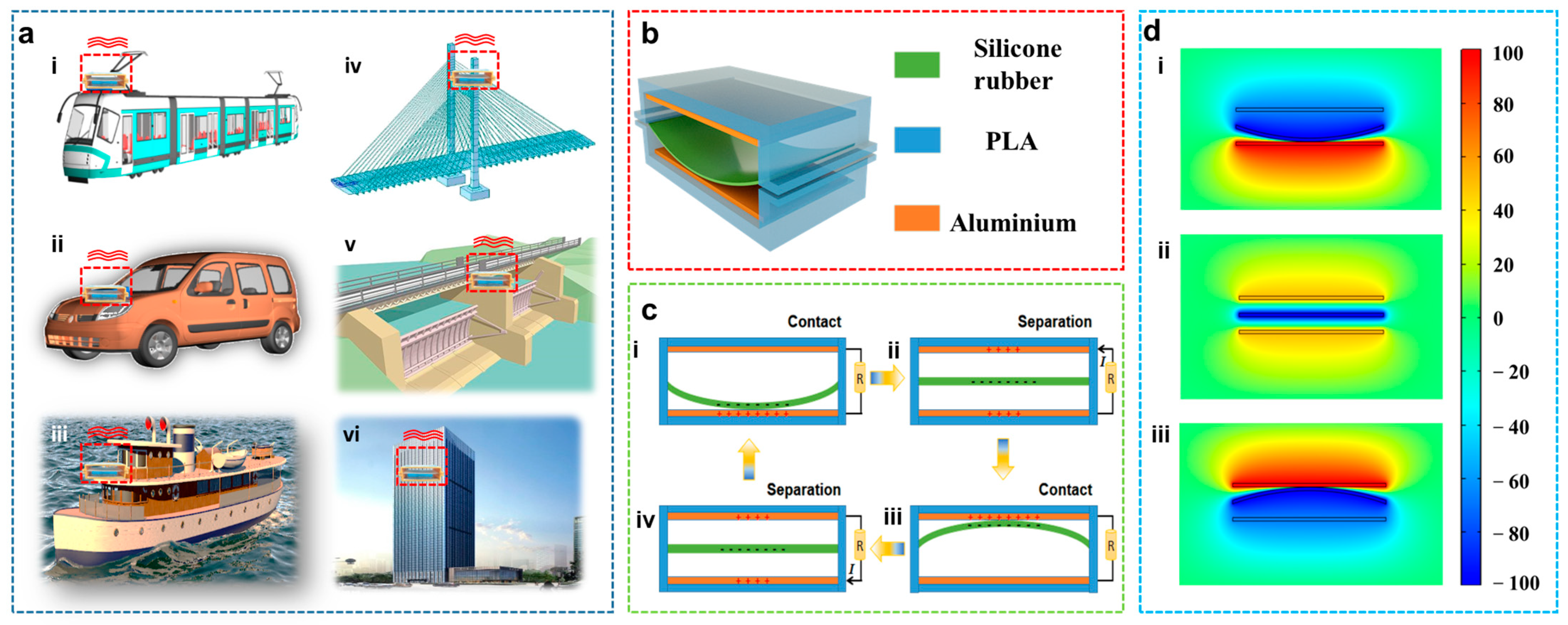
Abstract
:1. Introduction
2. Results and Discussion
2.1. Structure and Working Mechanism of the SRS-TENG
2.2. Theoretical Analysis
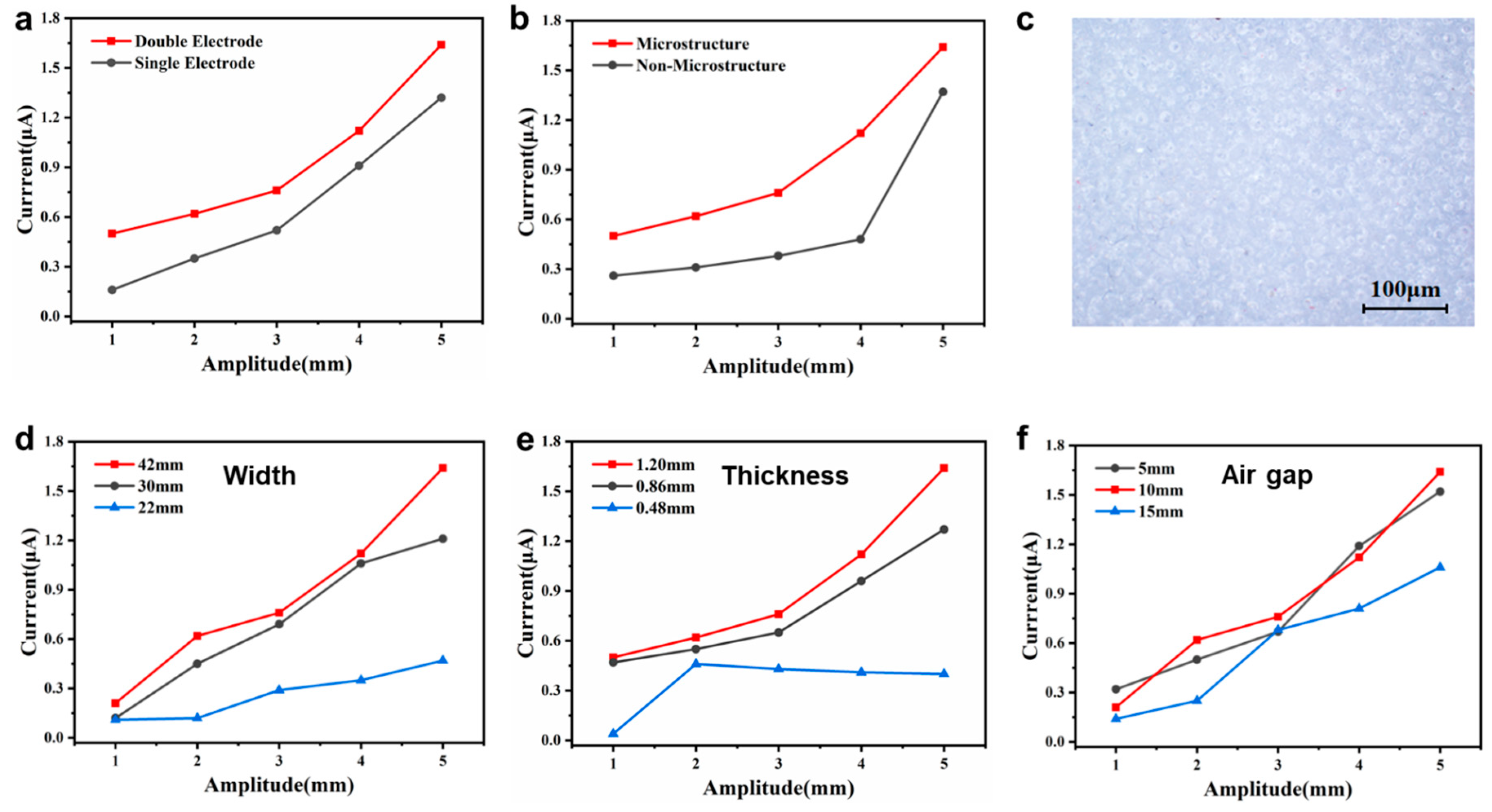
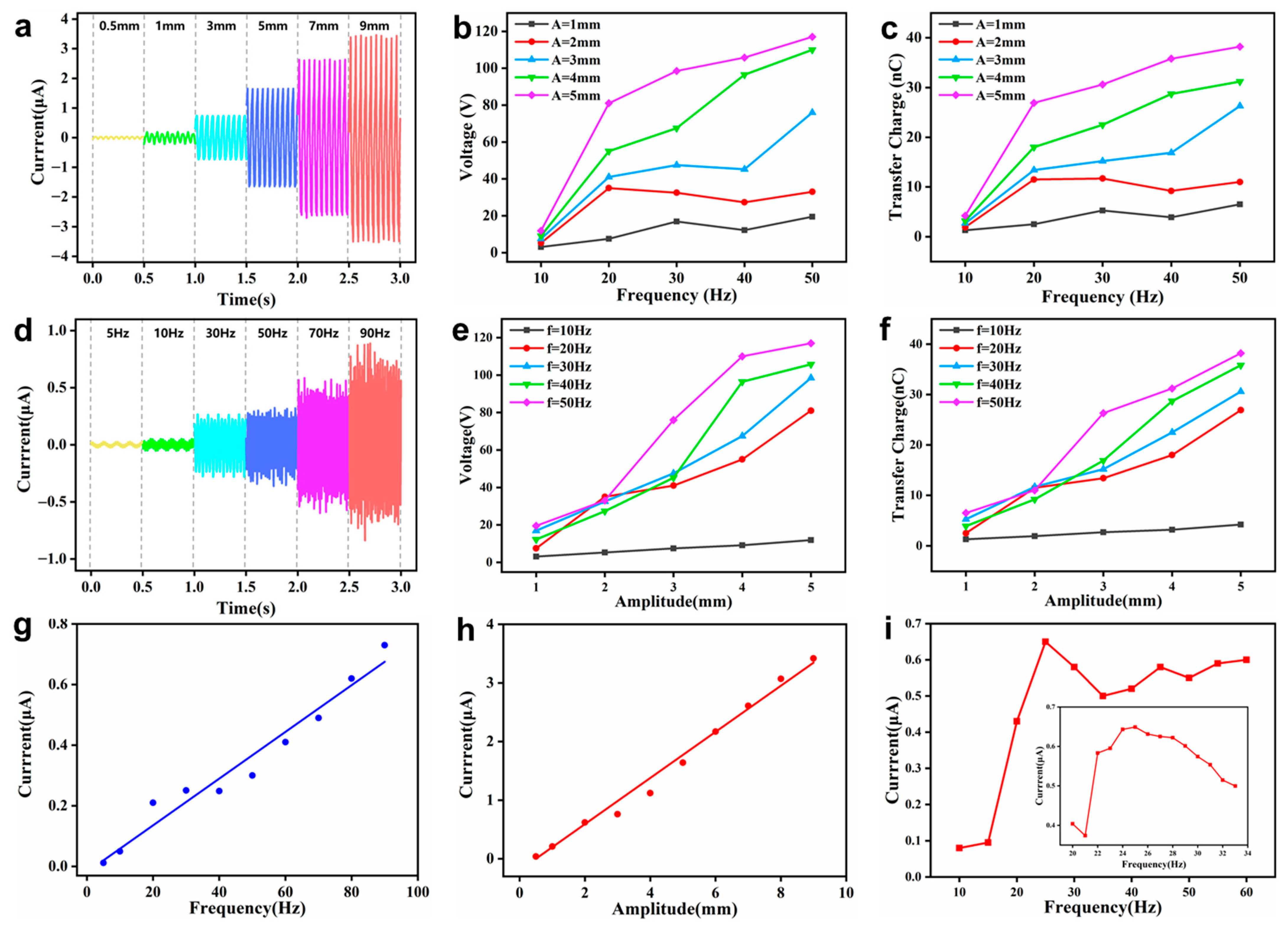
2.3. Working Performance of SRS-TENG
2.4. Demonstration
3. Conclusions
4. Experimental Section
4.1. Fabrication of the SRS-TENG
4.2. Observation of Movement of the Silicone Rubber Strip
4.3. Measurement of the Electric Output
Supplementary Materials
Author Contributions
Funding
Institutional Review Board Statement
Informed Consent Statement
Data Availability Statement
Conflicts of Interest
References
- Haight, R.; Haensch, W.; Friedman, D. Solar-powering the Internet of Things. Science 2016, 353, 124–125. [Google Scholar] [CrossRef] [PubMed]
- Meliopoulos, A.P.S.; Cokkinides, G.; Huang, R.K.; Farantatos, E.; Choi, S.Y.; Lee, Y.H.; Yu, X.B. Smart Grid Technologies for Autonomous Operation and Control. IEEE Trans. Smart Grid 2011, 2, 1–10. [Google Scholar]
- Murawski, L.; Dereszewski, M. Theoretical and practical backgrounds of monitoring system of ship power transmission systems’ torsional vibration. J. Mar. Sci. Technol. 2019, 25, 272–284. [Google Scholar] [CrossRef] [Green Version]
- Gkerekos, C.; Lazakis, I.; Theotokatos, G. Ship machinery condition monitoring using vibration data through supervised learning. In Proceedings of the International Conference of Maritime Safety and Operations (MSO), Glasgow, UK, 13–14 October 2016. [Google Scholar]
- Wu, Z.; Cheng, T.; Wang, Z.L. Self-Powered Sensors and Systems Based on Nanogenerators. Sensors 2020, 20, 2925. [Google Scholar]
- Kim, G.Y. Challenges for Rechargeable Li Batteries. Am. Chem. Soc. 2009, 22, 587–603. [Google Scholar]
- Pu, X.; Hu, W.; Wang, Z.L. Toward Wearable Self-Charging Power Systems: The Integration of Energy-Harvesting and Storage Devices. Small 2018, 14, 1702817. [Google Scholar] [CrossRef]
- Yi, M.; Chen, Q.; Xiong; N.N. An Effective Massive Sensor Network Data Access Scheme Based on Topology Control for the Internet of Things. Sensors 2014, 16, 1846. [Google Scholar]
- Chen, M.; Li, X.; Lin, L.; Du, W.; Han, X.; Zhu, J.; Pan, C.; Wang, Z.L. Triboelectric Nanogenerators as a Self-Powered Motion Tracking System. Adv. Funct. Mater. 2014, 24, 5059–5066. [Google Scholar]
- Luo, J.; Wang, Z.L. Recent progress of triboelectric nanogenerators: From fundamental theory to practical applications. EcoMat 2020, 2, 1–22. [Google Scholar] [CrossRef]
- Niu, S.; Wang, Z.L. Theoretical systems of triboelectric nanogenerators. Nano Energy 2015, 14, 161–192. [Google Scholar]
- Pei, C.; Wu, C.Y.; England, D.; Byard, S.; Berchtold, H.; Adams, M. Numerical analysis of contact electrification using DEM–CFD. Powder Technol. 2013, 248, 34–43. [Google Scholar] [CrossRef]
- Song, Y.; Wang, N.; Hu, C.; Wang, Z.L.; Yang, Y. Soft triboelectric nanogenerators for mechanical energy scavenging and self-powered sensors. Nano Energy 2021, 84, 105919. [Google Scholar] [CrossRef]
- Liu, Y.; Wang, K.; Wu, C.; Park, J.H.; Kim, T.W. Triboelectric-nanogenerator-inspired light-emitting diode-in-capacitors for flexible operation in high-voltage and wireless drive modes. Nano Energy 2020, 78, 105281. [Google Scholar] [CrossRef]
- Wang, Z.L. Triboelectric nanogenerators as new energy technology and self-powered sensors—Principles, problems and perspectives. Faraday Discuss. 2015, 176, 447–458. [Google Scholar] [CrossRef] [PubMed]
- Wang, Z.L. Triboelectric Nanogenerator (TENG)—Sparking an Energy and Sensor Revolution. Adv. Energy Mater. 2020, 10, 2000137. [Google Scholar] [CrossRef] [Green Version]
- Gao, Q.; Cheng, T.; Wang, Z.L. Triboelectric mechanical sensors—Progress and prospects. Extrem. Mech. Lett. 2021, 42, 101100. [Google Scholar] [CrossRef]
- Chen, J.; Zhu, G.; Yang, W.; Jing, Q.; Bai, P.; Yang, Y.; Hou, T.C.; Wang, Z.L. Harmonic-resonator-based triboelectric nanogenerator as a sustainable power source and a self-powered active vibration sensor. Adv. Mater. 2013, 25, 6094–6099. [Google Scholar] [CrossRef]
- Xu, M.; Wang, P.; Wang, Y.-C.; Zhang, S.L.; Wang, A.C.; Zhang, C.; Wang, Z.; Pan, X.; Wang, Z.L. A Soft and Robust Spring Based Triboelectric Nanogenerator for Harvesting Arbitrary Directional Vibration Energy and Self-Powered Vibration Sensing. Adv. Energy Mater. 2018, 8, 1702432. [Google Scholar] [CrossRef]
- Bhatia, D.; Hwang, H.J.; Huynh, N.D.; Lee, S.; Lee, C.; Nam, Y.; Kim, J.G.; Choi, D. Continuous scavenging of broadband vibrations via omnipotent tandem triboelectric nanogenerators with cascade impact structure. Sci. Rep. 2019, 9, 8223. [Google Scholar] [CrossRef]
- Du, T.; Zuo, X.; Dong, F.; Li, S.; Mtui, A.E.; Zou, Y.; Zhang, P.; Zhao, J.; Zhang, Y.; Sun, P. A Self-Powered and Highly Accurate Vibration Sensor Based on Bouncing-Ball Triboelectric Nanogenerator for Intelligent Ship Machinery Monitoring. Micromachines 2021, 12, 218. [Google Scholar] [CrossRef]
- Wang, Y.; Wang, J.; Xiao, X.; Wang, S.; Kien, P.T.; Dong, J.; Mi, J.; Pan, X.; Wang, H.; Xu, M. Multi-functional wind barrier based on triboelectric nanogenerator for power generation, self-powered wind speed sensing and highly efficient windshield. Nano Energy 2020, 73, 104736. [Google Scholar] [CrossRef]
- Xiao, X.; Zhang, X.; Wang, S.; Ouyang, H.; Chen, P.; Song, L.; Yuan, H.; Ji, Y.; Wang, P.; Li, Z.; et al. Honeycomb Structure Inspired Triboelectric Nanogenerator for Highly Effective Vibration Energy Harvesting and Self-Powered Engine Condition Monitoring. Adv. Energy Mater. 2019, 9, 1902460. [Google Scholar] [CrossRef]
- Yang, B.; Zeng, W.; Peng, Z.H.; Liu, S.R.; Chen, K.; Tao, X.M. A Fully Verified Theoretical Analysis of Contact-Mode Triboelectric Nanogenerators as a Wearable Power Source. Adv. Energy Mater. 2016, 6, 1600505. [Google Scholar] [CrossRef]
- He, Z.; Zhang, D.; Song, L.; Li, Y.; Wang, S. Nonlinear vibration analysis of orthotropic membrane. J. Vib. Shock 2018, 37, 252–259, 264. [Google Scholar]
- Song, W.; Du, L.; Zhang, Y.; Yin, H.; Liu, C. Strongly Nonlinear Damped Vibration of Orthotropic Membrane under Initial Displacement: Theory and Experiment. J. Vib. Eng. Technol. 2021, 9, 1359–1372. [Google Scholar] [CrossRef]
- Rohan, E.; Miara, B.; Seifrt, F. Numerical simulation of acoustic band gaps in homogenized elastic composites. Int. J. Eng. Sci. 2009, 47, 573–594. [Google Scholar] [CrossRef]
- Li, S.; Zhou, Y.; Zi, Y.; Zhang, G.; Wang, Z.L. Excluding Contact Electrification in Surface Potential Measurement Using Kelvin Probe Force Microscopy. ACS Nano 2016, 10, 2528–2535. [Google Scholar] [CrossRef]
- Xu, C.; Wang, A.C.; Zou, H.; Zhang, B.; Zhang, C.; Zi, Y.; Pan, L.; Wang, P.; Feng, P.; Lin, Z.; et al. Raising the Working Temperature of a Triboelectric Nanogenerator by Quenching Down Electron Thermionic Emission in Contact-Electrification. Adv. Mater. 2018, 30, 1803968. [Google Scholar] [CrossRef]
- Vasandani, P.; Mao, Z.H.; Jia, W.; Sun, M. Relationship between triboelectric charge and contact force for two triboelectric layers. J. Electrost. 2017, 90, 147–152. [Google Scholar] [CrossRef]
- Wang, A.C. Mechanism of Contact Electrification and Improved Performance of Triboelectric Nanogenerators via Surface Modification with Functional Materials. Ph.D. Thesis, Georgia Institute of Technology, Atlanta, GA, USA, August 2020. [Google Scholar]
- Zhao, L.; Zheng, Q.; Ouyang, H.; Li, H.; Yan, L.; Shi, B.; Li, Z. A size-unlimited surface microstructure modification method for achieving high performance triboelectric nanogenerator. Nano Energy 2016, 28, 172–178. [Google Scholar] [CrossRef]


Publisher’s Note: MDPI stays neutral with regard to jurisdictional claims in published maps and institutional affiliations. |
© 2022 by the authors. Licensee MDPI, Basel, Switzerland. This article is an open access article distributed under the terms and conditions of the Creative Commons Attribution (CC BY) license (https://creativecommons.org/licenses/by/4.0/).
Share and Cite
Du, T.; Ge, B.; Mtui, A.E.; Zhao, C.; Dong, F.; Zou, Y.; Wang, H.; Sun, P.; Xu, M. A Robust Silicone Rubber Strip-Based Triboelectric Nanogenerator for Vibration Energy Harvesting and Multi-Functional Self-Powered Sensing. Nanomaterials 2022, 12, 1248. https://0-doi-org.brum.beds.ac.uk/10.3390/nano12081248
Du T, Ge B, Mtui AE, Zhao C, Dong F, Zou Y, Wang H, Sun P, Xu M. A Robust Silicone Rubber Strip-Based Triboelectric Nanogenerator for Vibration Energy Harvesting and Multi-Functional Self-Powered Sensing. Nanomaterials. 2022; 12(8):1248. https://0-doi-org.brum.beds.ac.uk/10.3390/nano12081248
Chicago/Turabian StyleDu, Taili, Bin Ge, Anaeli Elibariki Mtui, Cong Zhao, Fangyang Dong, Yongjiu Zou, Hao Wang, Peiting Sun, and Minyi Xu. 2022. "A Robust Silicone Rubber Strip-Based Triboelectric Nanogenerator for Vibration Energy Harvesting and Multi-Functional Self-Powered Sensing" Nanomaterials 12, no. 8: 1248. https://0-doi-org.brum.beds.ac.uk/10.3390/nano12081248