Thermo-Electro-Mechanical Vibrations of Porous Functionally Graded Piezoelectric Nanoshells


1
Department of Mechanics, College of Sciences, Northeastern University, Shenyang 110819, China
2
Key Laboratory of Ministry of Education on Safe Mining of Deep Metal Mines, Northeastern University, Shenyang 110819, China
*
Author to whom correspondence should be addressed.
Nanomaterials 2019, 9(2), 301; https://0-doi-org.brum.beds.ac.uk/10.3390/nano9020301
Submission received: 29 January 2019
/
Revised: 15 February 2019
/
Accepted: 17 February 2019
/
Published: 20 February 2019
Abstract
:In this work, we aim to study free vibration of functionally graded piezoelectric material (FGPM) cylindrical nanoshells with nano-voids. The present model incorporates the small scale effect and thermo-electro-mechanical loading. Two types of porosity distribution, namely, even and uneven distributions, are considered. Based on Love’s shell theory and the nonlocal elasticity theory, governing equations and corresponding boundary conditions are established through Hamilton’s principle. Then, natural frequencies of FGPM nanoshells with nano-voids under different boundary conditions are analyzed by employing the Navier method and the Galerkin method. The present results are verified by the comparison with the published ones. Finally, an extensive parametric study is conducted to examine the effects of the external electric potential, the nonlocal parameter, the volume fraction of nano-voids, the temperature rise on the vibration of porous FGPM cylindrical nanoshells.
1. Introduction
Piezoelectric materials are characterized by the excellent coupling between the electric and mechanical fields. Applying mechanical load to piezoelectric materials generates an electric field, while putting piezoelectric materials in an electric field creates mechanical strain in them. This two-way property has made piezoelectric materials ideal for making actuators and sensors [1,2,3,4]. Besides, the two-way action of turning mechanical energy to electric energy and vice versa has made piezoelectric materials useful in resonant ultrasonic inspection and micro/nano piezoelectric power generators [5,6,7].
Unfortunately, there are some deficiencies such as low resistance to external loads, creeping in high temperature, and high stress concentration in homogeneous piezoelectric materials. In order to eliminate these problems, functionally graded piezoelectric materials (FGPMs) were proposed. The concept of functionally graded materials was first proposed in the 1980s [8]. Functionally graded materials are generally composed of two different materials, and are characterized by continuous variations in both mechanical properties and material composition in one or more dimension(s). Likewise, FGPMs are generally composed of two different piezoelectric materials. They have many advantages such as multifunctionality, ability to control deformation, and minimization or removal of stress. Hence, FGPMs have received wide engineering applications [9,10,11,12,13]. In FGPMs, owing to the technical issues, nano-voids or porosities may occur within materials. It is reported that a considerable number of nanopores appeared in the functionally graded material during the preparation process by the non-pressure sintering technique [14]. Thus, it is necessary to consider the porosity effect on vibration characteristics of porous FGPM structures.
With the rapid development in nanotechnology, the FGPMs have potential to be used in functional and structural elements in micro/nano electromechanical systems. It is known that FGPM nanostructures possess significant mechanical, thermal, electrical, and other physical properties.
Piezoelectric nanostructures have the dimension ranging from a few nanometers to several hundred nanometers. On this scale, the size effect was observed in both experiments and simulations [15,16,17,18]. One of effective nonclassical continuum theories considering size effect for piezoelectric nanostructures is Eringen’s nonlocal theory [19,20,21]. Ke et al. [22] used this theory to analyze free vibration of piezoelectric nanobeams subjected to thermo-mechanical-electro loading. Afterwards, the vibration of functionally graded piezoelectric nanoplates using the nonlocal elasticity theory was studied by Jandaghian and Rahmani [23]. The thermo-mechanical-electric vibration of FGPM nanoplates was studied by Jandaghian and Rahmani [24]. The vibration and buckling analyses of the piezoelectric nanobeams were carried out by Liang et al. [25]. Yan and Jiang [26] studied the surface effects on the vibration and buckling of the piezoelectric nanoplates. It is noted that all the above-mentioned studies concentrated on the piezoelectric nano beams or plates.
Cylindrical nanoshells possess specific functions in micro/nano electromechanical system. The size-dependent dynamic analysis of nanoshells, however, is limited in the open literature. Among them, the free vibration of magneto-electro-elastic cylindrical nanoshells was investigated by Ghadiri and Safarpour [27]. Fang et al. [28] conducted the free vibration analyses of piezoelectric nano double-shells. The instability and vibration of functionally graded nanoshells with internal fluid flow were analyzed by Ansari et al. [29]. In framework of the nonlocal elasticity theory, Sun et al. [30] analyzed the bucking of functionally graded cylindrical nanoshells. Ke et al. [31] studied the free vibration of piezoelectric nanoshells under an electric voltage.
In this article, vibration behavior of porous FGPM nanoshells subjected to the thermal and electrical loads is studied for the first time. Governing equations are derived from Hamilton’s principle by using the nonlocal elasticity theory and Love’s thin shell theory. Then, natural frequencies of the nanoshells are evaluated by the Navier technique and the Galerkin technique. Detailed results are shown to explore the influences of several key factors on vibration characteristics of FGPM nanoshells with nano-voids.
2. Preliminaries
2.1. Nonlocal Elasticity Theory for FGPMs
In Eringen’s nonlocal elastic theory [19,20,21], nonlocal constitutive equations are written as [19,32]:
in which i, j, l, k = 1, 2, 3; εij, σij, ui, Ei and Di denote the components of the strain, stress, displacement, electric field, and electric displacement, respectively; ekij, cijkl, pi, βij and sik represent the components of the piezoelectric tensor, elasticity tensor, pyroelectric vector, thermal modulus tensor and the dielectric tensor, respectively; denotes the mass density; and ΔT are the electric potential and temperature change, respectively; is the nonlocal kernel function; represents the scale parameter; x’ represents all material point coordinates except x point in the area; represents the Euclidean Distance.
Equivalent differential forms can be used to represent the overall constitutive relation as follows [20]:
in which is the Laplace Operator.
2.2. Nonlocal Porous FGPM Cylindrical Nanoshell Model
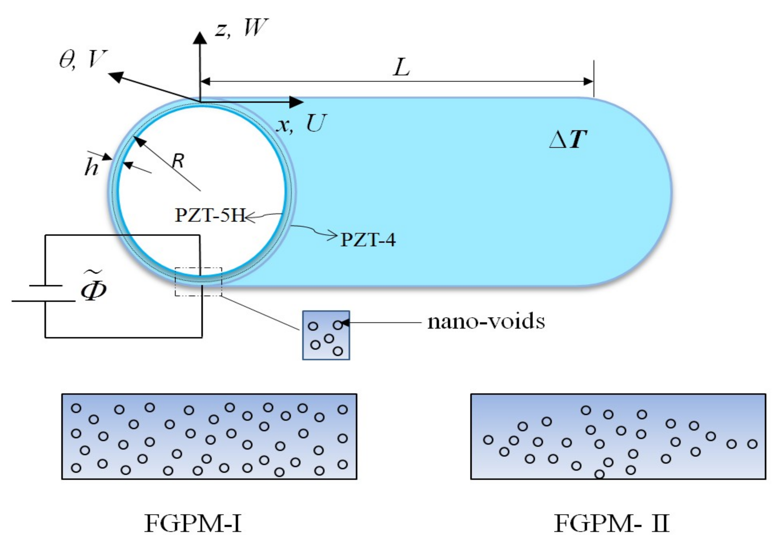
Consider a porous FGPM cylindrical nanoshell composed of PZT-5H and PZT-4. Figure 1 shows the geometry of the nanoshell with the thickness h, the middle-surface radius R and the length L. The FGPM nanoshell is supposed to contain nano-voids that disperse evenly (FGPM-I) or unevenly (FGPM-II) along the thickness direction. Additionally, the nanoshell is subjected to a uniform temperature change ΔT and electric potential . U(x, θ t), V(x, θ, t) and W(x, θ, t) are displacements of points at the middle plane of the shell in x-, θ- and z-axes directions, respectively.
The sum of PZT-5H and PZT-4 volume fractions is V4 + V5H = 1 [33]; For PZT-4, the volume fraction can be written as [34,35,36]:
where the parameter N ∈ [0, ∞) represents the power-law index.
For the FGPM-I nanoshell, the general material properties are given by [37]
where z is the distance from the mid-surface of the FGPM cylindrical nanoshell; P4 and P5H are material properties of PZT-4 and PZT-5H, respectively; α is the porosity volume fraction.
Therefore, the elastic constants cij, the piezoelectric constants eij, the mass density ρ, and the dielectric constants sij of the FGPM-I nanoshell can be expressed as:
For the FGPM-II nanoshell, on the other hand, the material properties in Equations (9)–(12) can be replaced by [38]
According to the Kirchhoff–Love hypothesis, the displacement fields are [39]:
in which t is time, and , and are the displacements of an arbitrary point along the x-, θ- and z-axes, respectively.
Using Love’s first approximation shell theory, the strain-displacement relations can be written as [40]:
Following Wang [41], the distribution of electric potential along the thickness of the FGPM nanoshell is assumed as:
in which ; V0 represents the initial external electric voltage applied to the FGPM nanoshell; Φ(x, θ, t) represents the spatial and time variation of the electric potential in the x-direction and θ-direction.
Using Equation (23), the electric field components Ei are given by
For the porous FGPM cylindrical nanoshell, the nonlocal constitutive relationship (5) and (6) can be given by [42,43]
in which ; , , , , and are defined as:
The strain energy of the porous FGPM cylindrical nanoshell is expressed as follows:
Substituting Equations (20)–(22) and Equations (24)–(26) into Equation (29) gives
in which the resultant forces and the moments can be respectively calculated as
The kinetic energy is given by:
in which , and the rotatory inertia term is neglected due to its slight impact.
Moreover, the work done by external forces can be written as:
in which (,)and (,) are the electrical and thermal forces induced by the uniform external electric voltage V0 and uniform temperature rise ΔT, respectively. They are given by
Using Hamilton’s principle [44,45]:
and applying Equations (29), (33), and (34), it yields the governing equations:
where
The corresponding boundary conditions are:
where nx and nθ denote the direction cosines of the outward unit normal to the boundaries of the mid-plane.
From Equation (27), we obtain the following equations:
where
Substituting Equations (48)–(56) into Equations (37)–(40) gives
The electric potential at both ends of the FGPM nanoshell is assumed to be zero. Then, the associated boundary conditions are expressed as
for a simply-supported end, and
for a clamped end.
3. Solution Procedure
3.1. Navier Procedure
For the porous FGPM cylindrical nanoshell with simply supported-simply supported (SS-SS) boundary condition, analytical solutions of the free vibration problem can be obtained utilizing Navier’s method. For this purpose, the following displacement functions which satisfy the SS-SS boundary condition are introduced:
where , , and represent the displacement amplitude components; m and n are mode numbers; ω represents the natural circular frequency of the porous FGPM nanoshell.
Substituting Equations (63)–(66) into Equations (57)–(60), the following equation can be obtained
The elements in the above matrix are given in the Appendix A Equation (A1). Equation (67) gives the characteristic equation for the natural frequencies of the porous FGPM cylindrical nanoshell. To obtain a nontrivial solution, the determinant of the coefficient matrix must be set to zero.
3.2. Galerkin Solution
For clamped-simply supported (C-SS) and clamped-clamped (C-C) boundary conditions, the spatial displacement field of the porous FGPM nanoshell is expressed as [46]:
Thereinto, the axial modal beam function ϕ(x) could be written as:
where the constants c1, c2, c3, c4, ζi and λi (i = 1, 2, 3, 4…) are given in Table 1.
Inserting Equations (68)–(71) in Equations (57)–(60) and applying the Galerkin method, we obtain:
in which the matrices M and K are the mass matrix and stiffness matrix of the porous FGPM cylindrical nanoshell, respectively.
4. Results and Discussion
For examining the validity of the present analysis, the comparison is performed on natural frequencies of a PZT-4 piezoelectric cylindrical nanoshell. Table 2, Table 3 and Table 4 list the natural frequencies of the piezoelectric nanoshell under different boundary conditions with h = 1 nm, R/h = 50, L/R = 12, m = 1, ΔT = 0, and V0 = 0. Material properties of PZT-4 are shown in Table 5. It is found that the present results match those given by Ke et al. [31] very well, bespeaking the validity of the present study.
In the following sections, free vibration of the porous FGPM cylindrical nanoscale shell shown in Figure 1 is performed; the material properties of the nanoshell are displayed in Table 5. If not specified, the following parameters are used:
h = 0.1 nm, R/h = 50, L/R = 6,
m = 1, N = 1, α = 0.1, V0 = 0, ΔT = 0, e0a = 2 nm
m = 1, N = 1, α = 0.1, V0 = 0, ΔT = 0, e0a = 2 nm
In Table 6, Table 7 and Table 8, the variation of natural frequency of the FGPM-I nanoshell against the circumferential wave number is represented for different porosity volume fractions and different boundary conditions, where N = 20. Among them, α = 0 corresponds to the FGPM cylindrical nanoshell without nano-voids. The results reveal that the natural frequency decreases as the porosity volume fraction increases. With the increase of the circumferential wave number, it is seen that the natural frequency decreases first and then increases. In addition, under the same condition, the SS-SS porous FGPM nanoshell has the lowest natural frequency while the C-C one has the highest natural frequency. This is because the end support is the weakest (in terms of stiffness) for the SS-SS FGPM nanoshell and the strongest for the C-C one. Under the SS-SS boundary condition, it is seen that the minimum natural frequency occurs at n = 3. Therefore, the fundamental frequency of the SS-SS FGPM nanoshell corresponds to mode (m = 1, n = 3). In the next studies, the SS-SS FGPM nanoshell is taken as an example and the mode (1,3) is chosen as a representative mode.
Natural frequency against the radius-to-thickness ratio for different porosity volume fractions is plotted for the FGPM-I nanoshell in Table 9. As the radius-to-thickness ratio increases, one can see that the natural frequency decreases initially and then increases; the frequency does not change monotonously with the radius-to-thickness ratio.
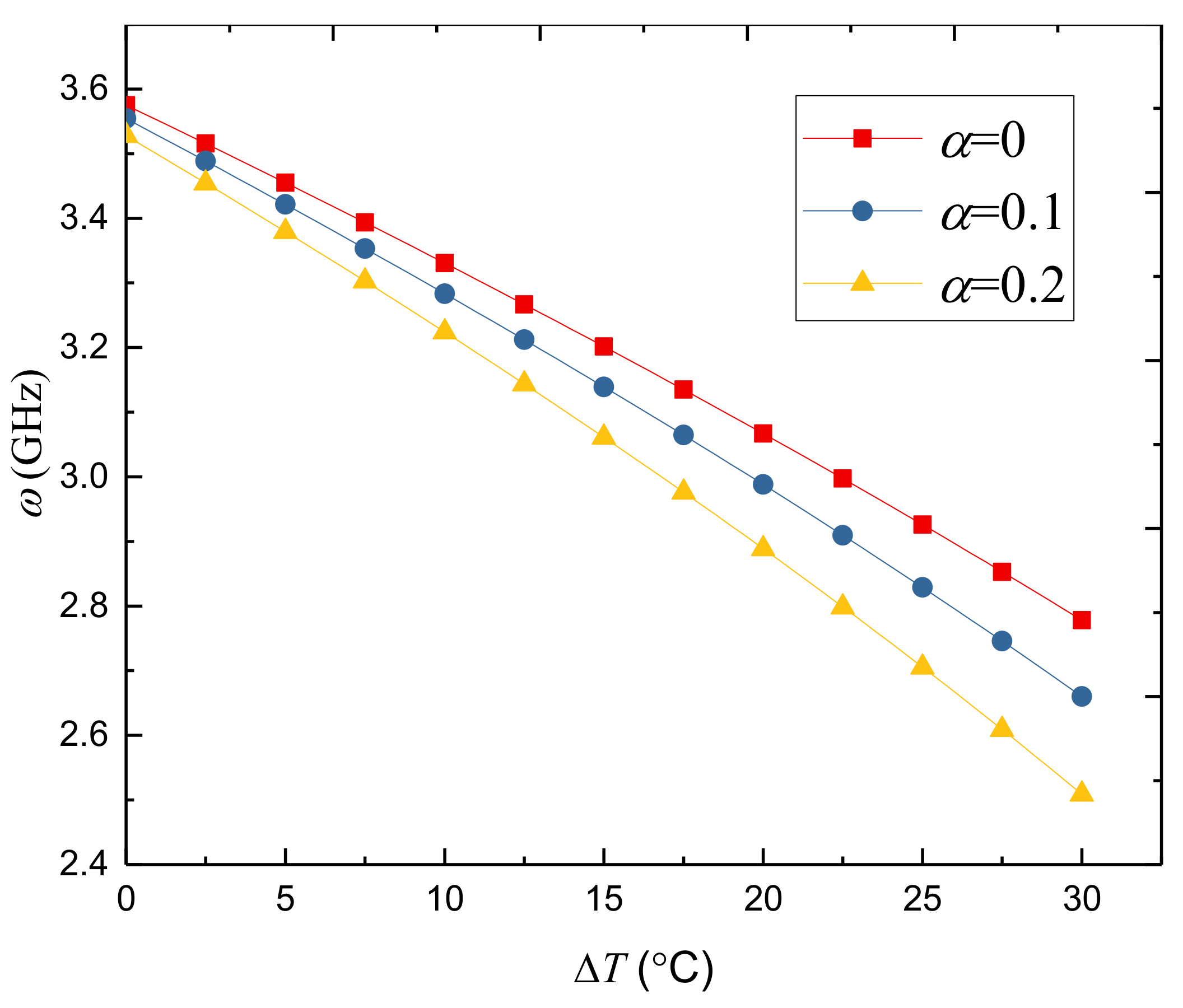
Figure 2 presents the effect of temperature change on the natural frequency of the FGPM-I nanoshell. The natural frequency decreases with the increase of temperature change. This is due to the fact that the larger temperature change results in a reduction in the stiffness and hence leads to the lower natural frequency of the porous FGPM nanoshell.
Table 10 illustrates the natural frequency against the circumferential wave number for different power-law indexes of the FGPM-I nanoshell. The natural frequencies of the FGPM nanoshell decreases with the increase of the power-law index. Additionally, it is seen that the fundamental natural frequency occurs at mode (m = 1, n = 3), which does not change with the power-law index.
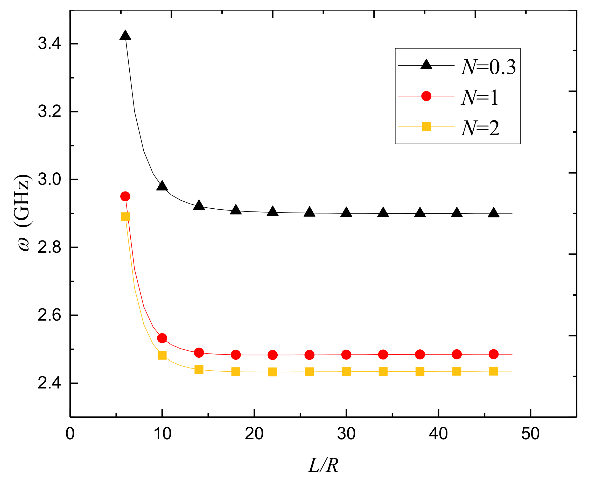
Figure 3 gives the variation of the natural frequency against the length-to-radius ratio for different power-law indexes. As a whole, it is observed that the natural frequency is quite susceptive to the length-to-radius ratio when this ratio is small; the frequency drops quickly as the length-to-radius ratio increases of the porous FGPM nanoshell. However, when L/R > 15, the natural frequency is no longer sensitive to the length-to-radius ratio change.
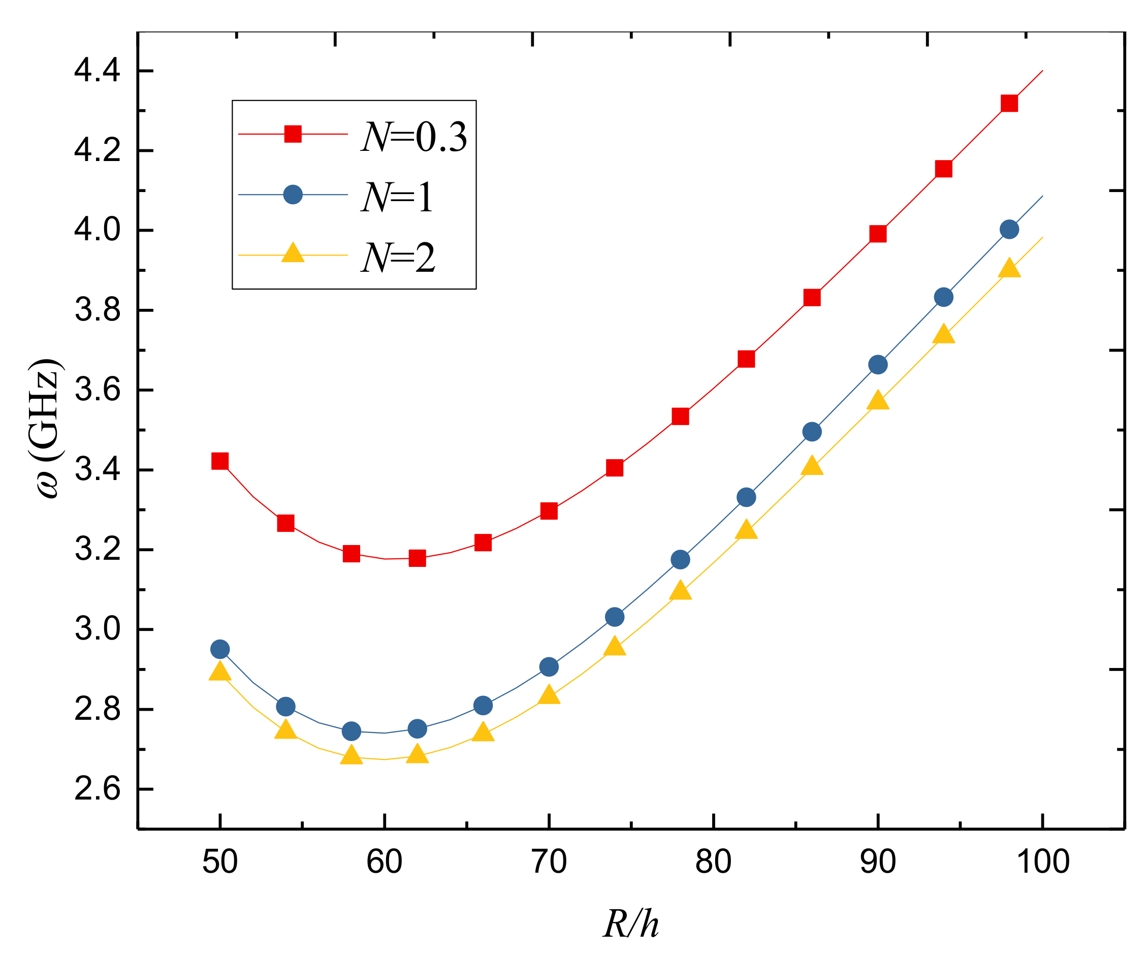
Figure 4 presents the variation of natural frequency against the radius-to-thickness ratio for different power-law indexes. The natural frequency decreases first and then increases as the radius-to-thickness ratio increases. A trend can also be observed that the natural frequency decreases gradually with the increase of the power-law index.
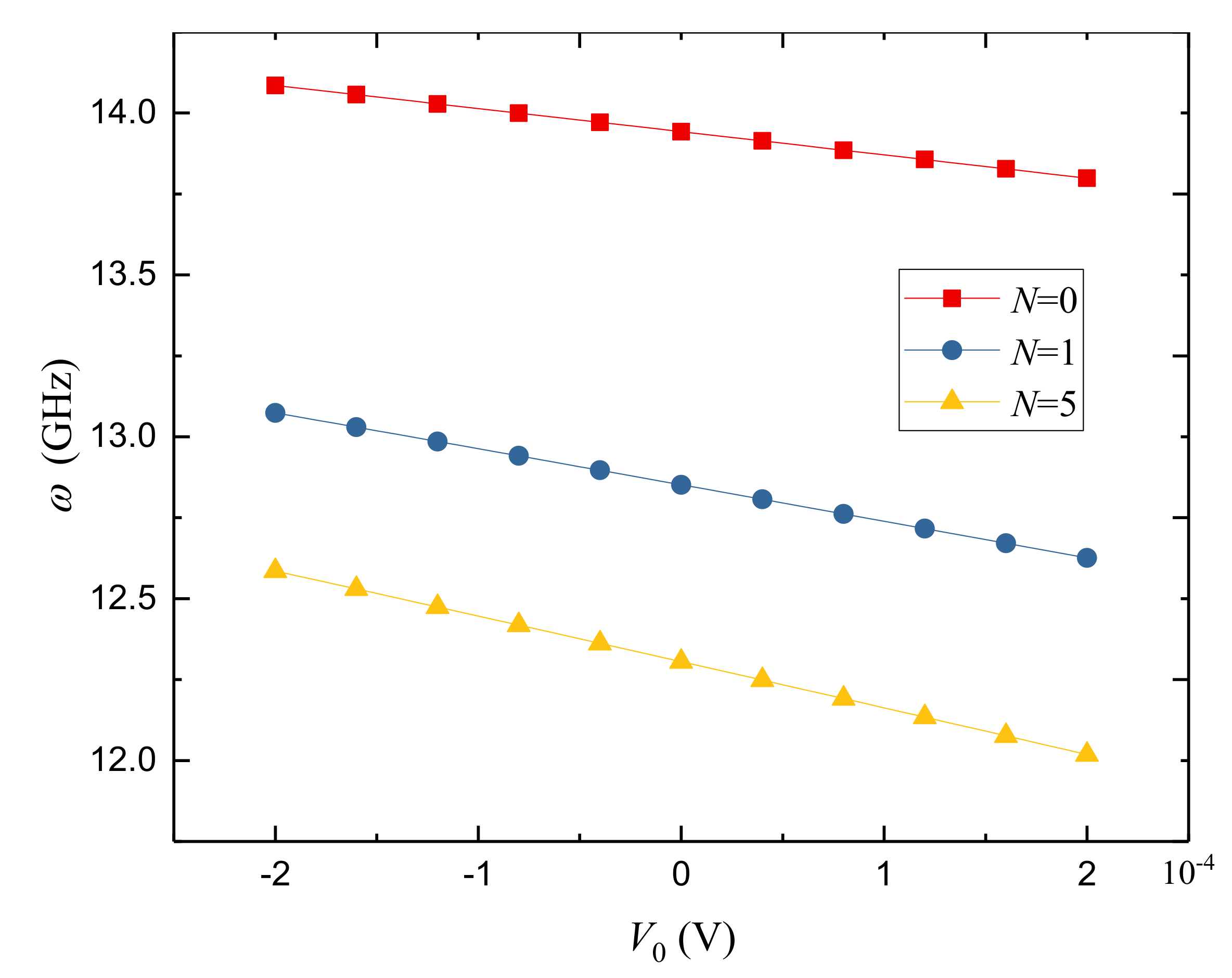
The variation of the natural frequency against external electric potential V0 for different power-law indexes is presented in Figure 5. Here, N = 0 corresponds to the cylindrical nanoshell made of pure PZT-4. As we can see, the natural frequency is quite sensitive to the applied external electric voltage. The natural frequency decreases as the voltage changes from V0 = −0.0002 V to 0.0002 V. The reason is that the axial and circumferential compressive and tensile forces are generated in the porous FGPM nanoshells by the applied positive and negative voltages, respectively. Thereinto, the applied positive voltage reduces the nanoshell stiffness but the negative voltage increases the nanoshell stiffness.
Table 11 presents the variation of nonlocal parameter against natural frequency of the FGPM-I nanoshell. One can see that the frequency decreases gradually with the increasing nonlocal parameter. This is because the nonlocal effect tends to decrease the stiffness of the nanoshell and hence decreases the natural frequency. This phenomenon was also found in nano-beams and nano-plates [56,57,58].
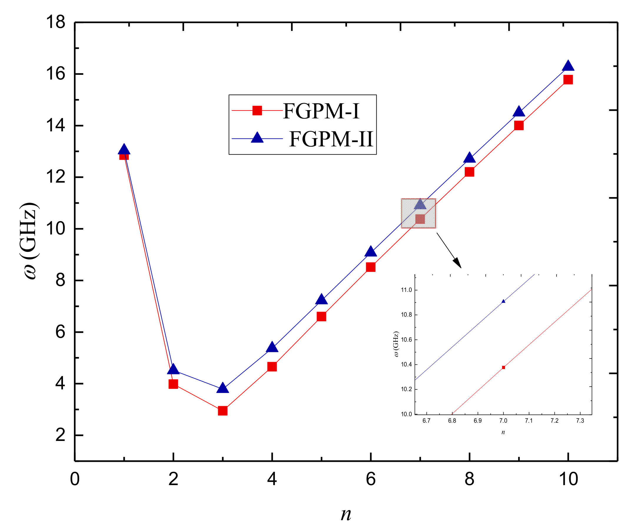
In order to reveal the porosity type effect, the natural frequency against the circumferential wave number for FGPM-I and FGPM-II nanoshells is plotted in Figure 6. One can see that the natural frequency of the FGPM-II nanoshell is close to that of the FGPM-I one at small circumferential wave number. However, the natural frequency of the FGPM-II nanoshell becomes higher than that of its FGPM-I counterpart with the rise of circumferential wave number. The difference between them gets more and more obvious as the circumferential wave number increases further.
Table 12 gives the natural frequencies of FGPM-I and FGPM-II nanoshells for various porosity volume fractions. One can find that the larger nano-void volume fraction leads to the lower natural frequency of the FGPM-I nanoshell, while it leads to the higher natural frequency of the FGPM-II nanoshell. Therefore, it can be concluded that the porosity distribution type has a notable impact on vibration characteristics of FGPM nanoshells.
5. Conclusions
In this work, free vibration of porous FGPM nanoshells subjected to thermal and electrical loads is studied in the framework of Love’s shell theory and nonlocal elasticity theory. Size-dependent governing equations and boundary conditions are obtained based on Hamilton’s principle. Then, natural frequencies of the porous FGPM cylindrical nanoshells are obtained via the Navier method as well as the Galerkin method. The following conclusions were drawn:
- (1)
- The fundamental natural frequency of the porous FGPM nanoshell decreases initially and then increases as the radius-to-thickness ratio increases. Furthermore, the fundamental frequency decreases with the rise of the length-to-radius ratio; especially, the frequency changes notably when the length-to-radius ratio is small;
- (2)
- Applying positive voltage decreases the stiffness while applying negative voltage increases the stiffness of the porous FGPM cylindrical nanoshell. Furthermore, the temperature rise results in a reduction in the stiffness. In addition, the larger power-law index leads to the lower natural frequencies of the porous FGPM cylindrical nanoshell;
- (3)
- The nonlocal parameter has a softening effect on the free vibrations of the porous FGPM nanoscale shells;
- (4)
- The Galerkin solution procedure is an alternative method, which can give numerical results with satisfactory accuracy;
- (5)
- Increasing the porosity volume fraction has a different effect on the natural frequencies of the FGPM-I and FGPM-II nanoshells, which shows that the porosity distribution type plays a notable role on vibration characteristics of the FGPM nanoscale shells.
Author Contributions
Data curation, Y.F.L.; Formal analysis, Y.F.L.; Funding acquisition, Y.Q.W.; Investigation, Y.F.L.; Methodology, Y.F.L.; Project administration, Y.Q.W.; Software, Y.F.L.; Supervision, Y.Q.W.; Validation, Y.F.L.; Writing—original draft, Y.F.L.; Writing—review & editing, Y.Q.W.
Funding
This research was supported by the National Natural Science Foundation of China (Grant no. 11672071) and the Fundamental Research Funds for the Central Universities (Grant no. N170504023).
Conflicts of Interest
The authors declare no conflict of interest.
Appendix A
References
- Gupta, V.; Sharma, M.; Thakur, N. Optimization criteria for optimal placement of piezoelectric sensors and actuators on a smart structure: A technical review. J. Intell. Mater. Syst. Struct. 2010, 21, 1227–1243. [Google Scholar] [CrossRef]
- Yang, M.; Qiao, P. Modeling and experimental detection of damage in various materials using the pulse-echo method and piezoelectric sensors/actuators. Smart Mater. Struct. 2005, 14, 1083–1100. [Google Scholar] [CrossRef]
- Aksel, E.; Jones, J.L. Advances in lead-free piezoelectric materials for sensors and actuators. Sensors 2010, 10, 1935–1954. [Google Scholar] [CrossRef] [PubMed]
- Rama, G. A 3-node piezoelectric shell element for linear and geometrically nonlinear dynamic analysis of smart structures. Facta Univ. Ser. Mech. Eng. 2017, 15, 31–44. [Google Scholar] [CrossRef]
- Schindel, D.W.; Hutchins, D.A.; Grandia, W.A. Capacitive and piezoelectric air-coupled transducers for resonant ultrasonic inspection. Ultrasonics 1996, 34, 621–627. [Google Scholar] [CrossRef]
- Lu, F.; Lee, H.P.; Lim, S.P. Modeling and analysis of micro piezoelectric power generators for micro-electromechanical-systems applications. Smart Mater. Struct. 2003, 13, 57–63. [Google Scholar] [CrossRef]
- Araneo, R.; Rinaldi, A.; Notargiacomo, A.; Bini, F.; Pea, M.; Celozzi, S.; Marinozzi, F.; Lovat, G. Design concepts, fabrication and advanced characterization methods of innovative piezoelectric sensors based on ZnO nanowires. Sensors 2014, 14, 23539–23562. [Google Scholar] [CrossRef]
- Koizumi, M. FGM activities in Japan. Compos. Part B Eng. 1997, 28, 1–4. [Google Scholar] [CrossRef]
- Zhu, X.; Wang, Q.; Meng, Z. A functionally gradient piezoelectric actuator prepared by powder metallurgical process in PNN-PZ-PT system. J. Mater. Sci. Lett. 1995, 14, 516–518. [Google Scholar] [CrossRef]
- Wu, C.; Kahn, M.; Moy, W. Piezoelectric ceramics with functional gradients: A new application in material design. J. Am. Ceram. Soc. 1996, 79, 809–812. [Google Scholar] [CrossRef]
- Sakamura, J.; Yamada, K.; Nakamura, K. Equivalent network analysis of functionally graded piezoelectric transducers. Jpn. J. Appl. Phys. 2000, 39, 3150. [Google Scholar]
- Ballato, J.; Schwartz, R.; Ballato, A. Network formalism for modeling functionally gradient piezoelectric plates and stacks and simulations of RAINBOW ceramic actuators. IEEE Trans. Ultrason. Ferroelectr. Freq. Control 2001, 48, 462–476. [Google Scholar] [CrossRef]
- Takahashi, S.; Miyamoto, N.; Ichinose, N. Functionally gradient piezoelectric ceramics for ultrasonic transducers. Jpn. J. Appl. Phys. 2002, 41, 7103. [Google Scholar] [CrossRef]
- Zhu, J.; Lai, Z.; Yin, Z.; Jeon, J.; Lee, S. Fabrication of ZrO2–NiCr functionally graded material by powder metallurgy. Mater. Chem. Phys. 2001, 68, 130–135. [Google Scholar] [CrossRef]
- Chen, C.Q.; Shi, Y.; Zhang, Y.S.; Zhu, J.; Yan, Y.J. Size dependence of Young’s modulus in ZnO nanowires. Phys. Rev. Lett. 2006, 96, 75505. [Google Scholar] [CrossRef]
- Park, T.-J.; Papaefthymiou, G.C.; Viescas, A.J.; Moodenbaugh, A.R.; Wong, S.S. Size-dependent magnetic properties of single-crystalline multiferroic BiFeO3 nanoparticles. Nano Lett. 2007, 7, 766–772. [Google Scholar] [CrossRef]
- Araneo, R.; Rinaldi, A.; Notargiacomo, A.; Bini, F.; Marinozzi, F.; Pea, M.; Lovat, G.; Celozzi, S. Effect of the scaling of the mechanical properties on the performances of ZnO piezo-semiconductive nanowires. AIP Conf. Proc. 2014, 1603, 14–22. [Google Scholar]
- Araneo, R.; Bini, F.; Rinaldi, A.; Notargiacomo, A.; Pea, M.; Celozzi, S. Thermal-electric model for piezoelectric ZnO nanowires. Nanotechnology 2015, 26, 265402. [Google Scholar] [CrossRef] [PubMed]
- Eringen, A.C. Nonlocal Continuum Field Theories; Springer: New York, NY, USA, 2002; ISBN 0387952756. [Google Scholar]
- Eringen, A.C. On differential equations of nonlocal elasticity and solutions of screw dislocation and surface waves. J. Appl. Phys. 1983, 54, 4703–4710. [Google Scholar] [CrossRef]
- Eringen, A.C. Nonlocal polar elastic continua. Int. J. Eng. Sci. 1972, 10, 1–16. [Google Scholar] [CrossRef]
- Ke, L.L.; Wang, Y.S. Thermoelectric-mechanical vibration of piezoelectric nanobeams based on the nonlocal theory. Smart Mater. Struct. 2012, 21, 025018. [Google Scholar] [CrossRef]
- Jandaghian, A.A.; Rahmani, O. Vibration analysis of functionally graded piezoelectric nanoscale plates by nonlocal elasticity theory: An analytical solution. Superlattices Microstruct. 2016, 100, 57–75. [Google Scholar] [CrossRef]
- Jandaghian, A.A.; Rahmani, O. Size-dependent free vibration analysis of functionally graded piezoelectric plate subjected to thermo-electro-mechanical loading. J. Intell. Mater. Syst. Struct. 2017, 28, 3039–3053. [Google Scholar] [CrossRef]
- Liang, X.; Hu, S.; Shen, S. Size-dependent buckling and vibration behaviors of piezoelectric nanostructures due to flexoelectricity. Smart Mater. Struct. 2015, 24, 105012. [Google Scholar] [CrossRef]
- Yan, Z.; Jiang, L.Y. Vibration and buckling analysis of a piezoelectric nanoplate considering surface effects and in-plane constraints. Proc. R. Soc. A 2012, 468, 3458–3475. [Google Scholar] [CrossRef]
- Ghadiri, M.; Safarpour, H. Free vibration analysis of embedded magneto-electro-thermo-elastic cylindrical nanoshell based on the modified couple stress theory. Appl. Phys. A 2016, 122, 833. [Google Scholar] [CrossRef]
- Fang, X.-Q.; Zhu, C.-S.; Liu, J.-X.; Liu, X.-L. Surface energy effect on free vibration of nano-sized piezoelectric double-shell structures. Phys. B Condens. Matter 2018, 529, 41–56. [Google Scholar] [CrossRef]
- Ansari, R.; Gholami, R.; Norouzzadeh, A. Size-dependent thermo-mechanical vibration and instability of conveying fluid functionally graded nanoshells based on Mindlin’s strain gradient theory. Thin-Walled Struct. 2016, 105, 172–184. [Google Scholar] [CrossRef]
- Sun, J.; Lim, C.W.; Zhou, Z.; Xu, X.; Sun, W. Rigorous buckling analysis of size-dependent functionally graded cylindrical nanoshells. J. Appl. Phys. 2016, 119, 214303. [Google Scholar] [CrossRef]
- Ke, L.L.; Wang, Y.S.; Reddy, J.N. Thermo-electro-mechanical vibration of size-dependent piezoelectric cylindrical nanoshells under various boundary conditions. Compos. Struct. 2014, 116, 626–636. [Google Scholar] [CrossRef]
- Ke, L.L.; Wang, Y.S.; Yang, J.; Kitipornchai, S. The size-dependent vibration of embedded magneto-electro-elastic cylindrical nanoshells. Smart Mater. Struct. 2014, 23, 125036. [Google Scholar] [CrossRef]
- Komijani, M.; Reddy, J.N.; Eslami, M.R. Nonlinear analysis of microstructure-dependent functionally graded piezoelectric material actuators. J. Mech. Phys. Solids 2014, 63, 214–227. [Google Scholar] [CrossRef]
- Wang, Y.Q.; Zu, J.W. Vibration behaviors of functionally graded rectangular plates with porosities and moving in thermal environment. Aerosp. Sci. Technol. 2017, 69, 550–562. [Google Scholar] [CrossRef]
- Wang, Y.Q.; Zu, J.W. Nonlinear steady-state responses of longitudinally traveling functionally graded material plates in contact with liquid. Compos. Struct. 2017, 164, 130–144. [Google Scholar] [CrossRef]
- Wang, Y.Q.; Zu, J.W. Nonlinear dynamics of a translational FGM plate with strong mode interaction. Int. J. Struct. Stab. Dyn. 2018, 18, 1850031. [Google Scholar] [CrossRef]
- Wang, Y.Q. Electro-mechanical vibration analysis of functionally graded piezoelectric porous plates in the translation state. Acta Astronaut. 2018, 143, 263–271. [Google Scholar] [CrossRef]
- Wattanasakulpong, N.; Chaikittiratana, A. Flexural vibration of imperfect functionally graded beams based on Timoshenko beam theory: Chebyshev collocation method. Meccanica 2015, 50, 1331–1342. [Google Scholar] [CrossRef]
- Amabili, M. Nonlinear Vibrations and Stability of Shells and Plates; Cambridge University Press: Cambridge, UK, 2008; ISBN 1139469029. [Google Scholar]
- Soedel, W. Vibrations of Shells and Plates; CRC Press: Boca Raton, FL, USA, 2004; ISBN 0203026306. [Google Scholar]
- Wang, Q. On buckling of column structures with a pair of piezoelectric layers. Eng. Struct. 2002, 24, 199–205. [Google Scholar] [CrossRef]
- Zhang, D.P.; Lei, Y.J.; Shen, Z.B. Thermo-electro-mechanical vibration analysis of piezoelectric nanoplates resting on viscoelastic foundation with various boundary conditions. Int. J. Mech. Sci. 2017, 131–132, 1001–1015. [Google Scholar] [CrossRef]
- Zhao, M.; Qian, C.; Lee, S.W.R.; Tong, P.; Suemasu, H.; Zhang, T.Y. Electro-elastic analysis of piezoelectric laminated plates. Adv. Compos. Mater. 2007, 16, 63–81. [Google Scholar] [CrossRef]
- Wang, Y.Q.; Wan, Y.H.; Zu, J.W. Nonlinear dynamic characteristics of functionally graded sandwich thin nanoshells conveying fluid incorporating surface stress influence. Thin-Walled Struct. 2019, 135, 537–547. [Google Scholar] [CrossRef]
- Wang, Y.Q.; Ye, C.; Zu, J.W. Nonlinear vibration of metal foam cylindrical shells reinforced with graphene platelets. Aerosp. Sci. Technol. 2019, 85, 359–370. [Google Scholar] [CrossRef]
- Loy, C.T.; Lam, K.Y. Vibration of cylindrical shells with ring support. Int. J. Mech. Sci. 1997, 39, 455–471. [Google Scholar] [CrossRef]
- Tornabene, F.; Fantuzzi, N.; Bacciocchi, M.; Viola, E. Effect of agglomeration on the natural frequencies of functionally graded carbon nanotube-reinforced laminated composite doubly-curved shells. Compos. Part B Eng. 2016, 89, 187–218. [Google Scholar] [CrossRef]
- Kamarian, S.; Salim, M.; Dimitri, R.; Tornabene, F. Free vibration analysis of conical shells reinforced with agglomerated Carbon Nanotubes. Int. J. Mech. Sci. 2016, 108, 157–165. [Google Scholar] [CrossRef]
- Nejati, M.; Dimitri, R.; Tornabene, F.; Hossein Yas, M. Thermal buckling of nanocomposite stiffened cylindrical shells reinforced by functionally graded wavy carbon nanotubes with temperature-dependent properties. Appl. Sci. 2017, 7, 1223. [Google Scholar] [CrossRef]
- Fantuzzi, N.; Tornabene, F.; Bacciocchi, M.; Dimitri, R. Free vibration analysis of arbitrarily shaped Functionally Graded Carbon Nanotube-reinforced plates. Compos. Part B Eng. 2017, 115, 384–408. [Google Scholar] [CrossRef]
- Tornabene, F.; Bacciocchi, M.; Fantuzzi, N.; Reddy, J.N. Multiscale approach for three-phase CNT/polymer/fiber laminated nanocomposite structures. Polym. Compos. 2017. [Google Scholar] [CrossRef]
- Nejati, M.; Asanjarani, A.; Dimitri, R.; Tornabene, F. Static and free vibration analysis of functionally graded conical shells reinforced by carbon nanotubes. Int. J. Mech. Sci. 2017, 130, 383–398. [Google Scholar]
- Kiani, Y.; Dimitri, R.; Tornabene, F. Free vibration study of composite conical panels reinforced with FG-CNTs. Eng. Struct. 2018, 172, 472–482. [Google Scholar] [CrossRef]
- Wang, Y.Q.; Huang, X.B.; Li, J. Hydroelastic dynamic analysis of axially moving plates in continuous hot-dip galvanizing process. Int. J. Mech. Sci. 2016, 110, 201–216. [Google Scholar] [CrossRef]
- Yang, J. Special Topics in the Theory of Piezoelectricity; Springer Science & Business Media: Berlin, Germany, 2010; ISBN 0387894985. [Google Scholar]
- Eltaher, M.A.; Hamed, M.A.; Sadoun, A.M.; Mansour, A. Mechanical analysis of higher order gradient nanobeams. Appl. Math. Comput. 2014, 229, 260–272. [Google Scholar] [CrossRef]
- Lim, C.W. Is a nanorod (or nanotube) with a lower Young’s modulus stiffer? Is not Young’s modulus a stiffness indicator? Sci. China Phys. Mech. Astron. 2010, 53, 712–724. [Google Scholar] [CrossRef]
- Ke, L.-L.; Liu, C.; Wang, Y.-S. Free vibration of nonlocal piezoelectric nanoplates under various boundary conditions. Phys. E Low-Dimens. Syst. Nanostruct. 2015, 66, 93–106. [Google Scholar] [CrossRef]
Figure 1.
Schematic of a porous functionally graded piezoelectric material (FGPM) circular cylindrical nanoshell.
Figure 1.
Schematic of a porous functionally graded piezoelectric material (FGPM) circular cylindrical nanoshell.

Figure 2.
Variation of natural frequency ω(GHz) against temperature change △T (°C) for different porosity volume fractions of the FGPM-I nanoshell (n = 3, N = 20).
Figure 2.
Variation of natural frequency ω(GHz) against temperature change △T (°C) for different porosity volume fractions of the FGPM-I nanoshell (n = 3, N = 20).

Figure 3.
Variation of natural frequency ω(GHz) against length-to-radius ratio for different power-law indexes N of FGPM-I nanoshell (n = 3).
Figure 3.
Variation of natural frequency ω(GHz) against length-to-radius ratio for different power-law indexes N of FGPM-I nanoshell (n = 3).

Figure 4.
Variation of the natural frequency ω(GHz) against the radius-to-thickness ratio for different power-law indexes N of FGPM-I nanoshell (n = 3, L = 300 h).
Figure 4.
Variation of the natural frequency ω(GHz) against the radius-to-thickness ratio for different power-law indexes N of FGPM-I nanoshell (n = 3, L = 300 h).

Figure 5.
Variation of natural frequency ω(GHz) against external electric potential V0 for different power-law indexes of FGPM-I nanoshell (n = 1).
Figure 5.
Variation of natural frequency ω(GHz) against external electric potential V0 for different power-law indexes of FGPM-I nanoshell (n = 1).

Figure 6.
Variation of the natural frequency ω(GHz) against the circumferential wave number of different types of porous FGPM nanoshell.
Figure 6.
Variation of the natural frequency ω(GHz) against the circumferential wave number of different types of porous FGPM nanoshell.


Table 1.
Values of c1, c2, c3, c4, ζi and λi for different boundary conditions.
| Boundary Condition | c1 | c2 | c3 | c4 | ζi | λi | ||||
|---|---|---|---|---|---|---|---|---|---|---|
| C-SS | 1 | −1 | 1 | −1 | 3.9266 | 7.0686 | 10.2102 | 13.3518 | … | |
| C-C | 1 | −1 | 1 | −1 | 4.7300 | 7.8532 | 10.9956 | 14.1372 | … | |
Table 2.
Comparison of natural frequency ω(GHz) of a SS-SS homogeneous piezoelectric nanoshell (μ = e0a/L).
Table 2.
Comparison of natural frequency ω(GHz) of a SS-SS homogeneous piezoelectric nanoshell (μ = e0a/L).
| n | μ = 0.02 | μ = 0.04 | ||
|---|---|---|---|---|
| Ke et al. [31] | Present | Ke et al. [31] | Present | |
| 1 | 0.4448 | 0.4448 | 0.4105 | 0.4105 |
| 2 | 0.2190 | 0.2190 | 0.1748 | 0.1748 |
| 3 | 0.4296 | 0.4296 | 0.3016 | 0.3016 |
| 4 | 0.7235 | 0.7235 | 0.4630 | 0.4630 |
| 5 | 1.0361 | 1.0361 | 0.6223 | 0.6223 |
| 6 | 1.3532 | 1.3532 | 0.7780 | 0.7780 |
| 7 | 1.6694 | 1.6694 | 0.9309 | 0.9309 |
| 8 | 1.9829 | 1.9829 | 1.0827 | 1.0827 |
| 9 | 2.2933 | 2.2933 | 1.2310 | 1.2310 |
| 10 | 2.6008 | 2.6008 | 1.3791 | 1.3791 |
Table 3.
Comparison of natural frequency ω(GHz) of a C-SS homogeneous piezoelectric nanoshell (μ = e0a/L).
Table 3.
Comparison of natural frequency ω(GHz) of a C-SS homogeneous piezoelectric nanoshell (μ = e0a/L).
| n | μ = 0.02 | μ = 0.04 | ||
|---|---|---|---|---|
| Ke et al. [31] | Present | Ke et al. [31] | Present | |
| 1 | 0.6189 | 0.6539 | 0.5710 | 0.6031 |
| 2 | 0.2701 | 0.2751 | 0.2155 | 0.2195 |
| 3 | 0.4357 | 0.4362 | 0.3058 | 0.3061 |
| 4 | 0.7247 | 0.7248 | 0.4637 | 0.4638 |
| 5 | 1.0365 | 1.0367 | 0.6225 | 0.6226 |
| 6 | 1.3534 | 1.3535 | 0.7781 | 0.7782 |
| 7 | 1.6695 | 1.6696 | 0.9309 | 0.9310 |
| 8 | 1.9830 | 1.9831 | 1.0817 | 1.0818 |
| 9 | 2.2934 | 2.2935 | 1.2310 | 1.2311 |
| 10 | 2.6008 | 2.6009 | 1.3791 | 1.3792 |
Table 4.
Comparison of natural frequency ω(GHz) of a C–C homogeneous piezoelectric nanoshell (μ = e0a/L).
Table 4.
Comparison of natural frequency ω(GHz) of a C–C homogeneous piezoelectric nanoshell (μ = e0a/L).
| n | μ = 0.02 | μ = 0.04 | ||
|---|---|---|---|---|
| Ke et al. [31] | Present | Ke et al. [31] | Present | |
| 1 | 0.7987 | 0.8487 | 0.7368 | 0.7823 |
| 2 | 0.3386 | 0.3488 | 0.2702 | 0.2782 |
| 3 | 0.4458 | 0.4472 | 0.3129 | 0.3138 |
| 4 | 0.7266 | 0.7268 | 0.4649 | 0.4651 |
| 5 | 1.0371 | 1.0373 | 0.6228 | 0.6229 |
| 6 | 1.3536 | 1.3538 | 0.7782 | 0.7783 |
| 7 | 1.6696 | 1.6698 | 0.9310 | 0.9311 |
| 8 | 1.9830 | 1.9832 | 1.0818 | 1.0819 |
| 9 | 2.2934 | 2.2936 | 1.2310 | 1.2311 |
| 10 | 2.6008 | 2.6010 | 1.3791 | 1.3792 |
| Material | PZT-4 | PZT-5H |
|---|---|---|
| Elastic constants (GPa) | c11 = 132, c12 = 71, c13 = 73, c22 = 132, c23 = 73, c33 = 115, c66 = 30.5 | c11 = 126, c12 = 79.1, c13 = 83.9, c22 = 139, c23 = 83.9, c33 = 117, c66 = 23.5 |
| Piezoelectric constants (C/m2) | e31 = −4.1, e32 = −4.1, e33 = 14.1 | e31 = −6.5, e32 = −6.5, e33 = 23.3 |
| Dielectric constants (10−9 C/Vm) | s11 = 5.841, s33 = 7.124 | s11 = 15.05, s33 = 13.02 |
| Thermal moduli (105 N/km2) | β11 = 4.738, β22 = 4.738, β33 = 4.529 | β11 = 4.738, β22 = 4.738, β33 = 4.529 |
| Pyroelectric constant (10−6 C/N) | p3 = 25 | p3 = 25 |
| Mass density (kg/m3) | ρ = 7500 | ρ = 7500 |
Table 6.
Variation of the natural frequency ω(GHz) against the circumferential wave number n for different porosity volume fractions α of FGPM-I nanoshell (SS-SS).
Table 6.
Variation of the natural frequency ω(GHz) against the circumferential wave number n for different porosity volume fractions α of FGPM-I nanoshell (SS-SS).
| n | α = 0 | α = 0.1 | α = 0.2 |
|---|---|---|---|
| 1 | 12.216 | 12.120 | 11.998 |
| 2 | 4.212 | 4.176 | 4.131 |
| 3 | 3.575 | 3.554 | 3.528 |
| 4 | 5.129 | 5.109 | 5.084 |
| 5 | 6.934 | 6.912 | 6.884 |
| 6 | 8.737 | 8.712 | 8.680 |
| 7 | 10.514 | 10.486 | 10.450 |
| 8 | 12.267 | 12.235 | 12.195 |
| 9 | 14.000 | 13.965 | 13.920 |
| 10 | 15.718 | 15.679 | 15.630 |
Table 7.
Variation of the natural frequency ω(GHz) against circumferential wave number n for different porosity volume fractions α of FGPM-I nanoshell (C-SS).
Table 7.
Variation of the natural frequency ω(GHz) against circumferential wave number n for different porosity volume fractions α of FGPM-I nanoshell (C-SS).
| n | α = 0 | α = 0.1 | α = 0.2 |
|---|---|---|---|
| 1 | 15.958 | 15.833 | 15.675 |
| 2 | 6.000 | 5.951 | 5.889 |
| 3 | 4.042 | 4.017 | 3.985 |
| 4 | 5.223 | 5.202 | 5.176 |
| 5 | 6.961 | 6.939 | 6.911 |
| 6 | 8.750 | 8.724 | 8.692 |
| 7 | 10.522 | 10.493 | 10.458 |
| 8 | 12.273 | 12.241 | 12.201 |
| 9 | 14.005 | 13.969 | 13.925 |
| 10 | 15.722 | 15.683 | 15.634 |
Table 8.
Variation of the natural frequency ω(GHz) against circumferential wave number n for different porosity volume fractions α of FGPM-I nanoshell (C-C).
Table 8.
Variation of the natural frequency ω(GHz) against circumferential wave number n for different porosity volume fractions α of FGPM-I nanoshell (C-C).
| n | α = 0 | α = 0.1 | α = 0.2 |
|---|---|---|---|
| 1 | 18.371 | 18.228 | 18.048 |
| 2 | 7.670 | 7.609 | 7.531 |
| 3 | 4.657 | 4.626 | 4.587 |
| 4 | 5.365 | 5.343 | 5.314 |
| 5 | 7.000 | 6.977 | 6.948 |
| 6 | 8.763 | 8.738 | 8.706 |
| 7 | 10.529 | 10.500 | 10.464 |
| 8 | 12.277 | 12.245 | 12.205 |
| 9 | 14.008 | 13.972 | 13.928 |
| 10 | 15.724 | 15.685 | 15.636 |
Table 9.
Variation of natural frequency ω(GHz) against the radius-to-thickness ratio R/h for different porosity volume fractions of FGPM-I nanoshell (n = 3, L = 300 h, N = 20).
Table 9.
Variation of natural frequency ω(GHz) against the radius-to-thickness ratio R/h for different porosity volume fractions of FGPM-I nanoshell (n = 3, L = 300 h, N = 20).
| R/h | α = 0 | α = 0.1 | α = 0.2 |
|---|---|---|---|
| 50 | 3.575 | 3.554 | 3.528 |
| 55 | 3.353 | 3.332 | 3.304 |
| 60 | 3.239 | 3.217 | 3.189 |
| 65 | 3.211 | 3.187 | 3.158 |
| 70 | 3.248 | 3.223 | 3.192 |
| 75 | 3.333 | 3.307 | 3.274 |
| 80 | 3.452 | 3.425 | 3.390 |
| 85 | 3.594 | 3.565 | 3.529 |
| 90 | 3.751 | 3.721 | 3.683 |
| 95 | 3.917 | 3.885 | 3.845 |
| 100 | 3.575 | 3.554 | 3.528 |
Table 10.
Variation of the natural frequency ω(GHz) against circumferential wave number n for different power-law indexes N of FGPM-I nanoshell.
Table 10.
Variation of the natural frequency ω(GHz) against circumferential wave number n for different power-law indexes N of FGPM-I nanoshell.
| n | N = 0.3 | N = 1 | N = 5 |
|---|---|---|---|
| 1 | 13.474 | 12.852 | 12.305 |
| 2 | 4.437 | 3.982 | 3.967 |
| 3 | 3.422 | 2.950 | 3.088 |
| 4 | 5.027 | 4.656 | 4.735 |
| 5 | 6.929 | 6.602 | 6.630 |
| 6 | 8.822 | 8.512 | 8.503 |
| 7 | 10.680 | 10.376 | 10.336 |
| 8 | 12.508 | 12.203 | 12.135 |
| 9 | 14.312 | 14.002 | 13.908 |
| 10 | 16.097 | 15.779 | 15.661 |
Table 11.
Variation of natural frequency ω(GHz) against the circumferential wave number n for different nonlocal parameter e0a of FGPM-I nanoshell.
Table 11.
Variation of natural frequency ω(GHz) against the circumferential wave number n for different nonlocal parameter e0a of FGPM-I nanoshell.
| n | e0a = 0 | e0a = 1 nm | e0a = 1.5 nm | e0a = 2 nm |
|---|---|---|---|---|
| 1 | 14.101 | 13.755 | 13.356 | 14.101 |
| 2 | 5.168 | 4.775 | 4.392 | 5.168 |
| 3 | 4.650 | 3.971 | 3.433 | 4.650 |
| 4 | 8.839 | 6.879 | 5.630 | 8.839 |
| 5 | 14.826 | 10.455 | 8.193 | 14.826 |
| 6 | 22.203 | 14.182 | 10.752 | 22.203 |
| 7 | 30.928 | 17.943 | 13.267 | 30.928 |
| 8 | 40.993 | 21.693 | 15.738 | 40.993 |
| 9 | 52.398 | 25.414 | 18.172 | 52.398 |
| 10 | 65.143 | 29.101 | 20.575 | 65.143 |
Table 12.
Variation of natural frequency ω(GHz) against length-to-radius ratio L/R of different types of porous FGPM cylindrical nanoshell (n = 3, N = 20).
Table 12.
Variation of natural frequency ω(GHz) against length-to-radius ratio L/R of different types of porous FGPM cylindrical nanoshell (n = 3, N = 20).
| L/R | α = 0 | α = 0.1 | α = 0.2 | ||
|---|---|---|---|---|---|
| Prefect | FGPM-I | FGPM-II | FGPM-I | FGPM-II | |
| 6 | 3.575 | 3.554 | 3.609 | 3.528 | 3.643 |
| 12 | 3.168 | 3.151 | 3.208 | 3.130 | 3.249 |
| 18 | 3.137 | 3.121 | 3.177 | 3.100 | 3.218 |
| 24 | 3.130 | 3.114 | 3.170 | 3.093 | 3.211 |
| 30 | 3.127 | 3.111 | 3.168 | 3.091 | 3.209 |
| 36 | 3.126 | 3.110 | 3.166 | 3.090 | 3.208 |
| 42 | 3.126 | 3.109 | 3.166 | 3.089 | 3.207 |
| 48 | 3.125 | 3.109 | 3.165 | 3.089 | 3.207 |
© 2019 by the authors. Licensee MDPI, Basel, Switzerland. This article is an open access article distributed under the terms and conditions of the Creative Commons Attribution (CC BY) license (http://creativecommons.org/licenses/by/4.0/).
Share and Cite
MDPI and ACS Style
Liu, Y.F.; Wang, Y.Q. Thermo-Electro-Mechanical Vibrations of Porous Functionally Graded Piezoelectric Nanoshells. Nanomaterials 2019, 9, 301. https://0-doi-org.brum.beds.ac.uk/10.3390/nano9020301
AMA Style
Liu YF, Wang YQ. Thermo-Electro-Mechanical Vibrations of Porous Functionally Graded Piezoelectric Nanoshells. Nanomaterials. 2019; 9(2):301. https://0-doi-org.brum.beds.ac.uk/10.3390/nano9020301
Chicago/Turabian StyleLiu, Yun Fei, and Yan Qing Wang. 2019. "Thermo-Electro-Mechanical Vibrations of Porous Functionally Graded Piezoelectric Nanoshells" Nanomaterials 9, no. 2: 301. https://0-doi-org.brum.beds.ac.uk/10.3390/nano9020301
Note that from the first issue of 2016, this journal uses article numbers instead of page numbers. See further details here.