Article

Study on Friction and Wear Properties of Zr–Cu–Ni–Al Crystalline Powder Cladding and Amorphous Composite Powder Cladding by Laser

Nano/Amorphous Materials and Devices Lab, School of Materials and Energy, Guangdong University of Technology, Guangzhou 510006, China
*
Author to whom correspondence should be addressed.
Submission received: 15 December 2020 / Revised: 14 January 2021 / Accepted: 15 January 2021 / Published: 18 January 2021
(This article belongs to the Special Issue Coatings for Corrosion Mitigation)

Abstract

:
In order to improve the friction and wear performance and surface hardness of AISI 1045 steel and expand its application range, this paper carried out the research on friction and wear performance and surface hardness of Zr65Al7.5Ni10Cu17.5 crystalline powder (CP) and amorphous powder (AP) after laser cladding on AISI 1045 steel surface. The results show that both CP and amorphous powder (AP) formed a cladding layer on the surface of AISI 1045 steel under laser irradiation. The thickness of the cladding layer is about 400 μm, and the thickness of the AP cladding layer is slightly larger than that of the CP cladding layer. The results show that there are many holes in the AP cladding layer, and holes can be observed at the junction with the matrix; while the CP cladding layer is well combined with the matrix and no holes are observed. The friction performance of CP cladding layer is better than that of AP cladding layer. In the wear marks of the AP cladding layer, there are bonding areas, while the wear marks of the CP cladding layer have a furrow-like morphology, and part of the matrix is exposed. The surface microhardness and average microhardness of AP cladding layer are 49% and 94% higher than that of CP cladding layer, respectively. Hardness modification has obvious advantages. The reasons for porosity, large friction coefficient and low stability of the friction experiment of the AP cladding layer are analyzed and discussed. The ideas and methods for improving the laser irradiation to achieve both high wear resistance and high strength of the AP cladding layer are proposed.

1. Introduction

AISI 1045 Steel is a daily steel for people, with high strength and forming ability, but its wear resistance and surface hardness are poor, so its use range is limited. In order to improve the surface properties and application range of AISI 1045 steel, the introduction of amorphous layer on the surface is an effective means. Currently, there are several methods used to produce amorphous coatings, such as thermal spray technology and laser cladding technology [1]. In recent years, laser cladding technology has attracted many people’s attention and has been used for commercial purposes to change the various surface characteristics of steel parts. The technology provides rapid cooling rate and opens the way for industrial application of metallic glass. The coating has excellent wear resistance and high surface hardness. The improvement of surface performance can greatly increase the application range of AISI 1045 steel, such as automobile crankshafts, automobile ball joints, micro gears, etc. Compared with other technologies, it has the ability to form various relatively thick protective layers, and the process method is more pure than the chemical process method [1,2,3,4,5,6,7,8].
Since the first synthesis of metallic amorphous phase in 1960, efforts have been made to develop glassy metallic alloys [9]. With the recently developed amorphous materials with large glass forming ability, metallic amorphous coatings can now be produced by laser cladding technology [6,10]. As for the mechanical properties of amorphous materials, it is found that bulk amorphous materials have low ductility, which limits the application of amorphous materials. In the development of amorphous materials, amorphous matrix composites (AMC) have received extensive attention in recent years. Although the corrosion resistance of AMC alloys may not be as good as that of bulk alloys, they have higher ductility and better mechanical properties [11]. In AMC, amorphous-nanocrystalline composites exhibit high hardness, high tensile strength, excellent wear resistance and ductility [12,13]. Since reheating amorphous materials to high temperatures is a common way of synthesizing these composites, multilayer laser cladding can be used to fabricate such composite coatings. When laser cladding is used to form amorphous coating on metal substrate, it is usually found that amorphous coating or crystalline coating can be formed according to the process parameters. Obviously, the phase composition of the coating will significantly affect the surface properties of the substrate. In 1997, Audebert [14] discovered that Zr-based alloys can be partially amorphous by laser surface treatment. Since then, the improvement of Zr-based amorphous and nanocrystalline coatings has been widely studied. In recent years, Yue and Subramanian have successfully strengthened magnesium matrix by laser cladding [15,16]. Zr65Al7.5Ni10Cu17.5 cladding layer was fabricated on magnesium substrate by laser cladding technology, which showed better properties than magnesium matrix [17]. It is conceivable that the coating with high strength and high wear resistance can be produced by forming appropriate amorphous composite on AISI 1045 steel substrate. In this context, the friction and wear properties and surface hardness of AISI 1045 steel after laser cladding Zr65Al7.5Ni10Cu
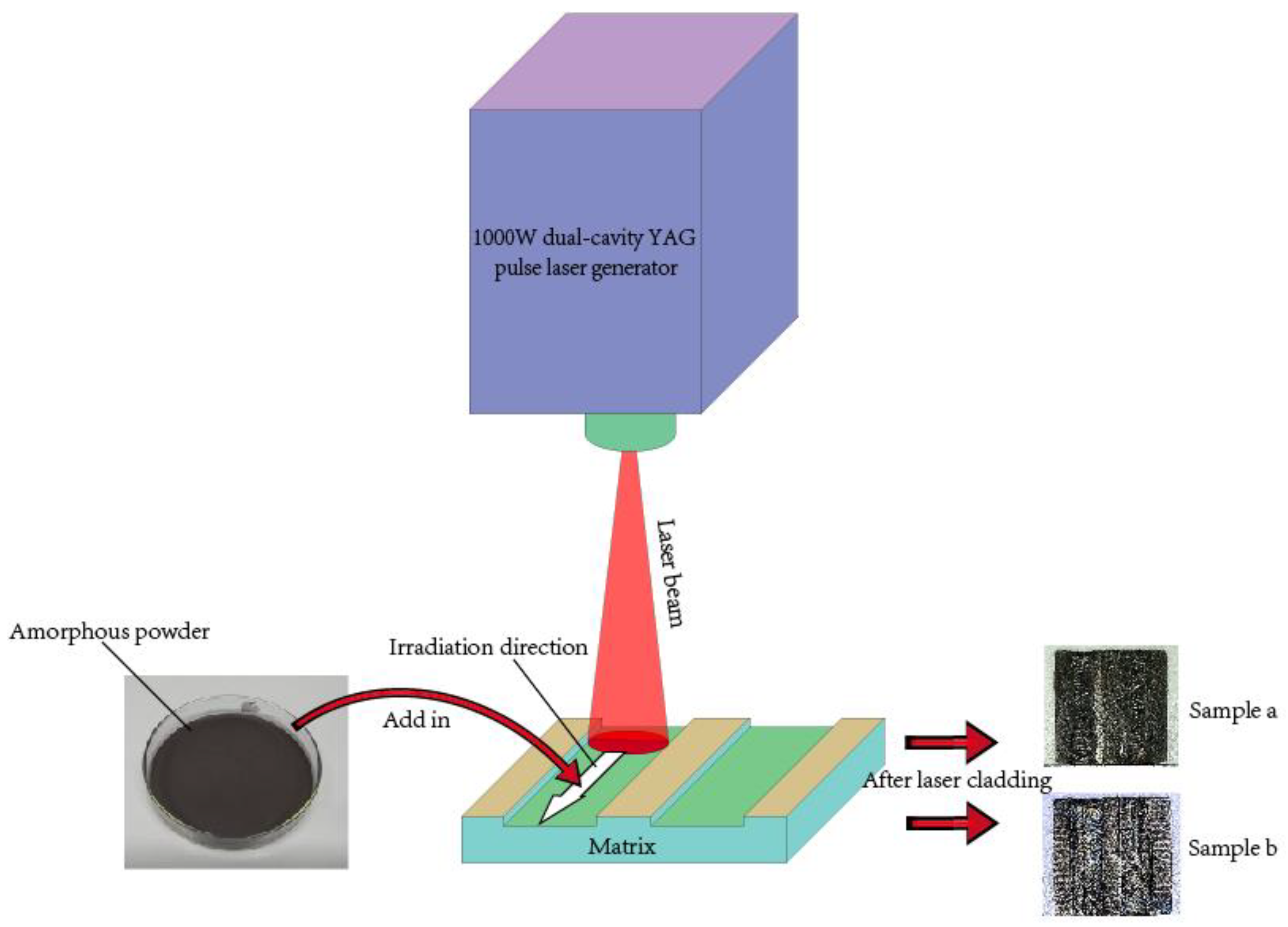
17.5 alloy powder and amorphous composite powder are studied in this paper, which provides ideas and basis for expanding the research field of amorphous alloy and promoting the industrial application of amorphous alloy. This article has guiding value or theoretical significance for the development of high-performance alloy coatings.

2. Experimental

2.1. Powders Preparation and Structure Characterization

The cladding material used in this paper is crystalline powder (CP) and amorphous powder (AP) composed of Zr65Al7.5Ni10Cu17.5. Arc melting from pure elements (purities above 99.96%) was used to prepare ingot with the targeted compositions of Zr65Al7.5Ni10Cu17.5 (at.%). After the ingot was mechanically broken, the powder with a particle size of 400 mesh was screened out. The sieved powder was crystal powder. Take part of the sieved powder for ball milling (The parameters are shown in Table 1) to obtain amorphous powder.
The Zr–Cu–Ni–Al CP and AP were analyzed by an X-ray Diffractometer (D/max-Ultima Type of IV, Rigaku, Osaka, Japan). The two powders were spread flat on the sample stage, and then the stage was placed in the X-ray diffractometer. The X-ray consisted of a Cu beam with a wavelength of 1.54 Å. The voltage and the current were set to 40 kV and 30 mA, respectively. The diffraction angle, 2θ, ranged between 20°–80°, in which data was recorded every 0.013 degrees.

2.2. Sample Preparation

The Zr-Cu-Ni-Al CP and AP cladding layers were fabricated by laser generator (XL-1000WF, Xinglai Laser Technology Co. Ltd, Guangzhou, China). Firstly, An AISI 1045 steel (The chemical compositions are shown in Table 2) sample (AISI 1045, Guangzhou Iron and Steel Group, Guangzhou, China) was taken and cut out two steel substrate samples in size 14 mm × 14 mm × 2 mm with a wire cutter machine. Then the oxide layer on the surface of AISI 1045 steel was grinded by 240 mesh sandpaper.
The substrates are then machined out of two milled grooves by a milling machine, with a width of 4 mm and a depth of 0.4 mm. The two substrates are labeled a and b respectively, AP cladding on a, and CP cladding on b. Further, Spread the pre-prepared CP and AP respectively in the grooves of the AISI 1045 steel matrix, set the parameters of the pulse laser generator as shown in Table 3, and hit the laser on the powder to melt the powder. After self-excited cooling, the molten powder will solidify and bond with the matrix.
Three pieces are cut from the sample prepared in this step, which are convenient for the following tests. Two pieces of 2 mm × 14 mm × 2 mm in size were used for hardness testing and OM, and another piece of 10 mm × 14 mm × 2 mm in size were used for friction wear testing. Place the sample in a soft plastic mold with the cross section facing down, and then pour the epoxy resin and ethylenediamine (according to the 2:1 ratio) into the mold. Put the mold in the drying oven until the epoxy resin is completely cured. The surfaces of the specimens were ground and polished in turn by using sandpapers with size of 240#, 600#, 1000# and 1500#, respectively. Then, Polish the sample with SiO2 polishing powder (Particle size: 0.25 μm) and polishing machine. The final surface roughness reaches about Ra0.02. The schematic diagram of the sample preparation process is shown in Figure 1.

2.3. Friction and Wear Test

The friction and wear properties of two cladding layers were tested by WTM-2E Mini-Tester (Zhongke Kaihua Company, Lanzhou, China) of Friction and Wear. This instrument can detect and collect signals in real time through the computer, and display the change curve of friction coefficient in real time. It is specially used to test the friction coefficient and wear resistance of various coatings or solid lubricating materials. This test was carried out at room temperature in the atmosphere, because AISI 1045 steel is for daily use which is usually served at room temperature. Place the test sample on the center of the sample platform, gently press the sample with a clamp of appropriate size, and then install the three fixing screws. Choose the bolt disc or ball disc indenter, install it on the indenter rod, and fix the locking nut. Rotate the lifting bracket adjustment nut according to the height of the sample and observe the level to make the loading beam parallel. Adjust the load beam weight balance slider to make the load beam at the balance position, and fix the balance slider nut. Start the running program after setting the parameters. The process parameters of friction and wear test are shown in Table 4.

2.4. Optical Microscopy

The optical microscopy of cross section of two samples were observed by high power optical microscope of Zeiss (Oberkochen, Germany).

2.5. Micro-Hardness Tests

The hardness of two samples were tested by THE HV-1000IS type of micro Vickers hardness Tester (HV-1000IS, Nuoen, Hangzhou, China). After the sample is polished by sandpaper and polished by a polishing machine, it is placed on the stage for testing. Start the test after checking that the diamond indenter of the hardness tester is not damaged. After the diamond indenter is pressed into the sample, a pit is formed on the surface of the sample. Align the crosshair of the microscope with the pit, and measure the diagonal length of the pit with an eyepiece micrometer. The instrument will automatically calculate the hardness value of the measured substance based on the applied load and the diagonal length of the pit. In order to reduce the influence of errors on the experimental results, the average value of 5 test points is selected as the final hardness value. The selected load was 300 gf, and the dwell time was 8 s.

3. Result and Discussion

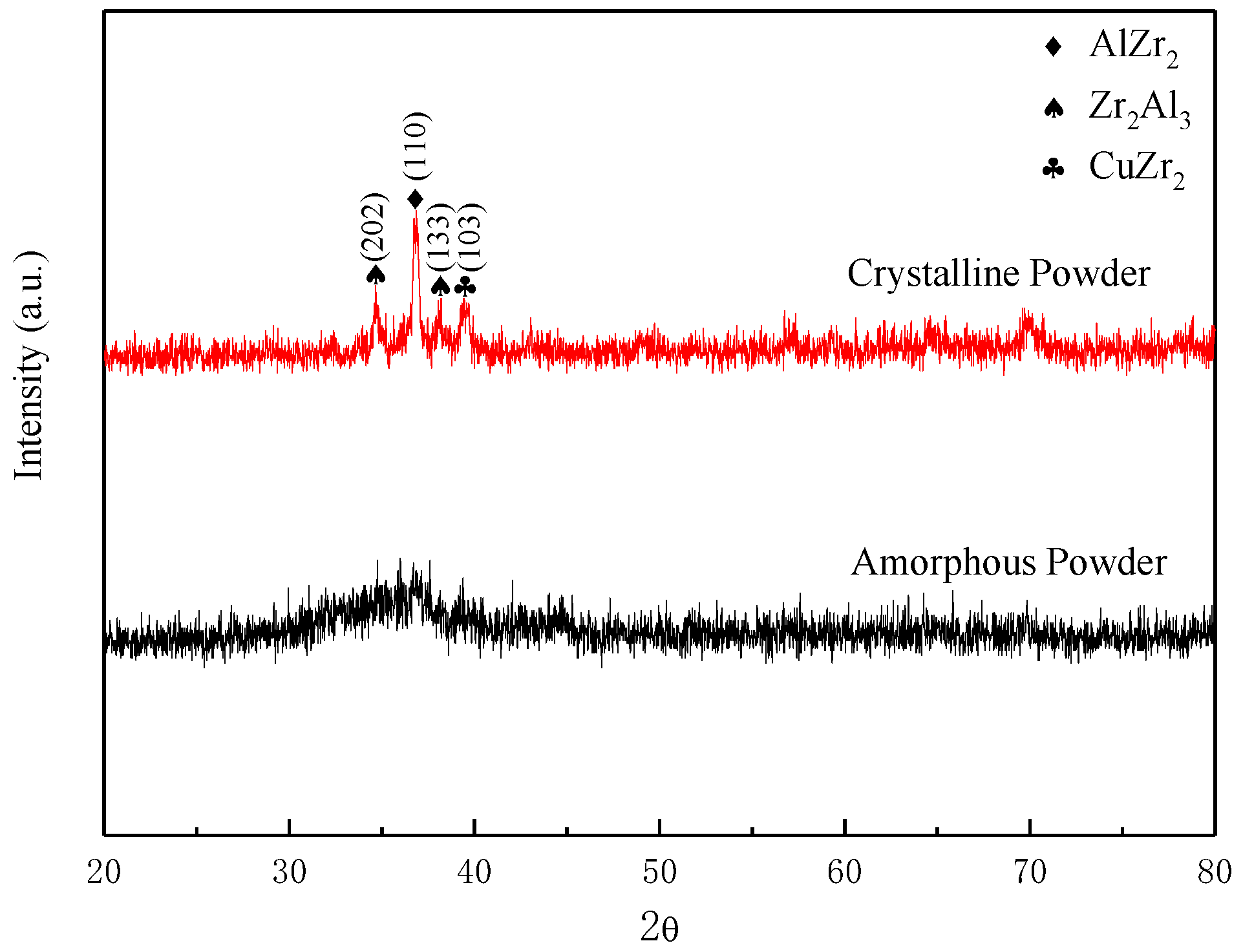
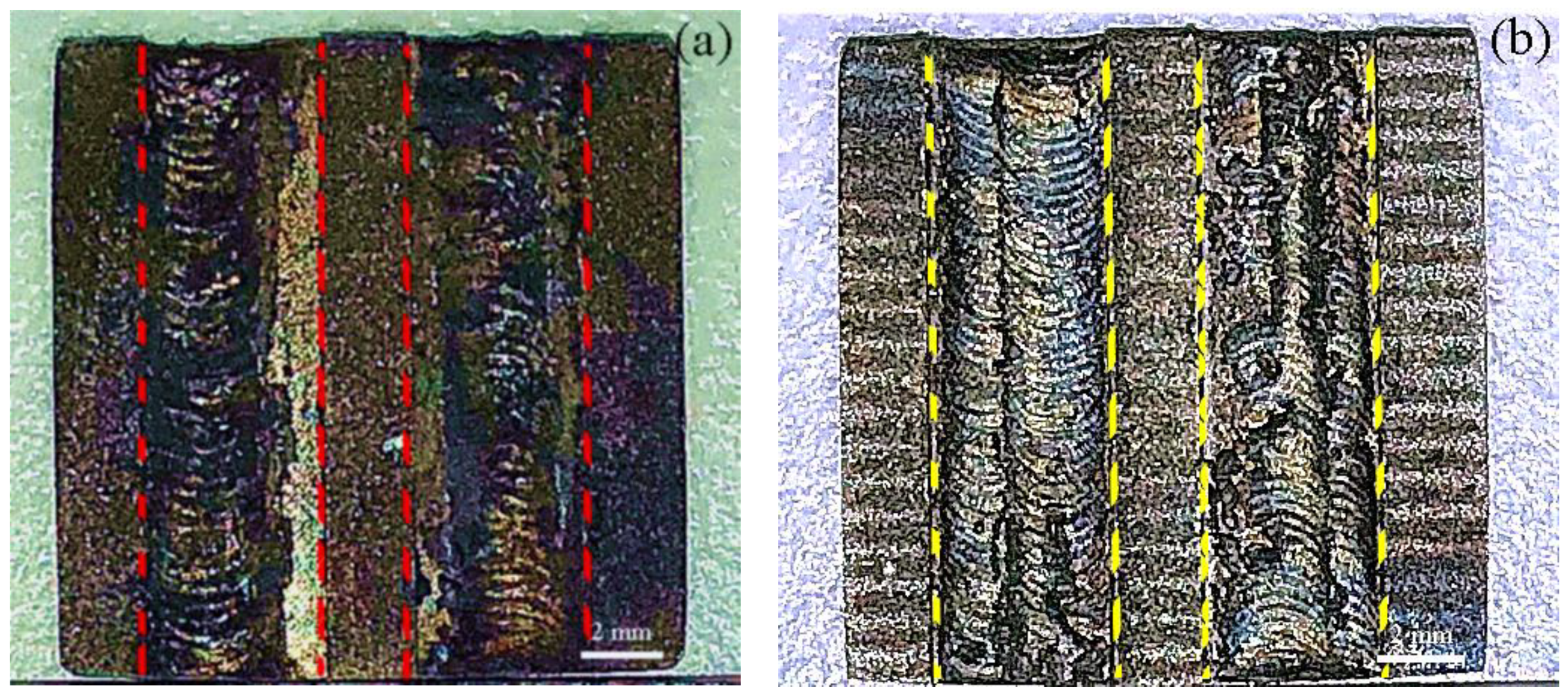
Figure 2 shows the XRD patterns of the prepared crystalline powder (CP) and amorphous powder (AP). It can be seen from the figure that the CP has a sharp diffraction peak at about 2θ = 38° and the amorphous powder presents a wide dispersion diffraction peak at about 2θ = 38°. The sample after laser cladding is shown in Figure 3, in which Figure 3a is the macro sample diagram of amorphous powder cladding layer, and Figure 3b is the macro sample diagram of composite powder cladding. It can be seen from the figure that in the small groove processed in AISI 1045 steel, the two alloy powders are melted and solidified to form a cladding layer under high-energy laser operation. Macroscopically, the surface of the cladding layer presents a dense and regular corrugated accumulation phenomenon.
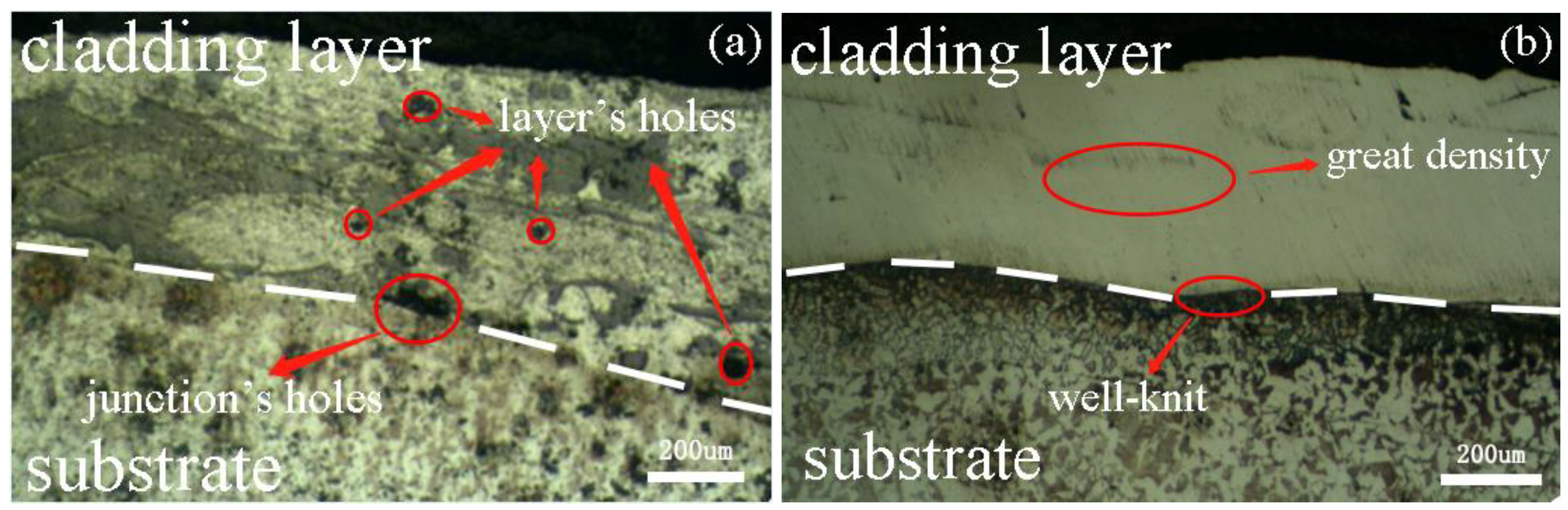
The cross-section optical micrographs of the two specimens with cladding layer are shown in 
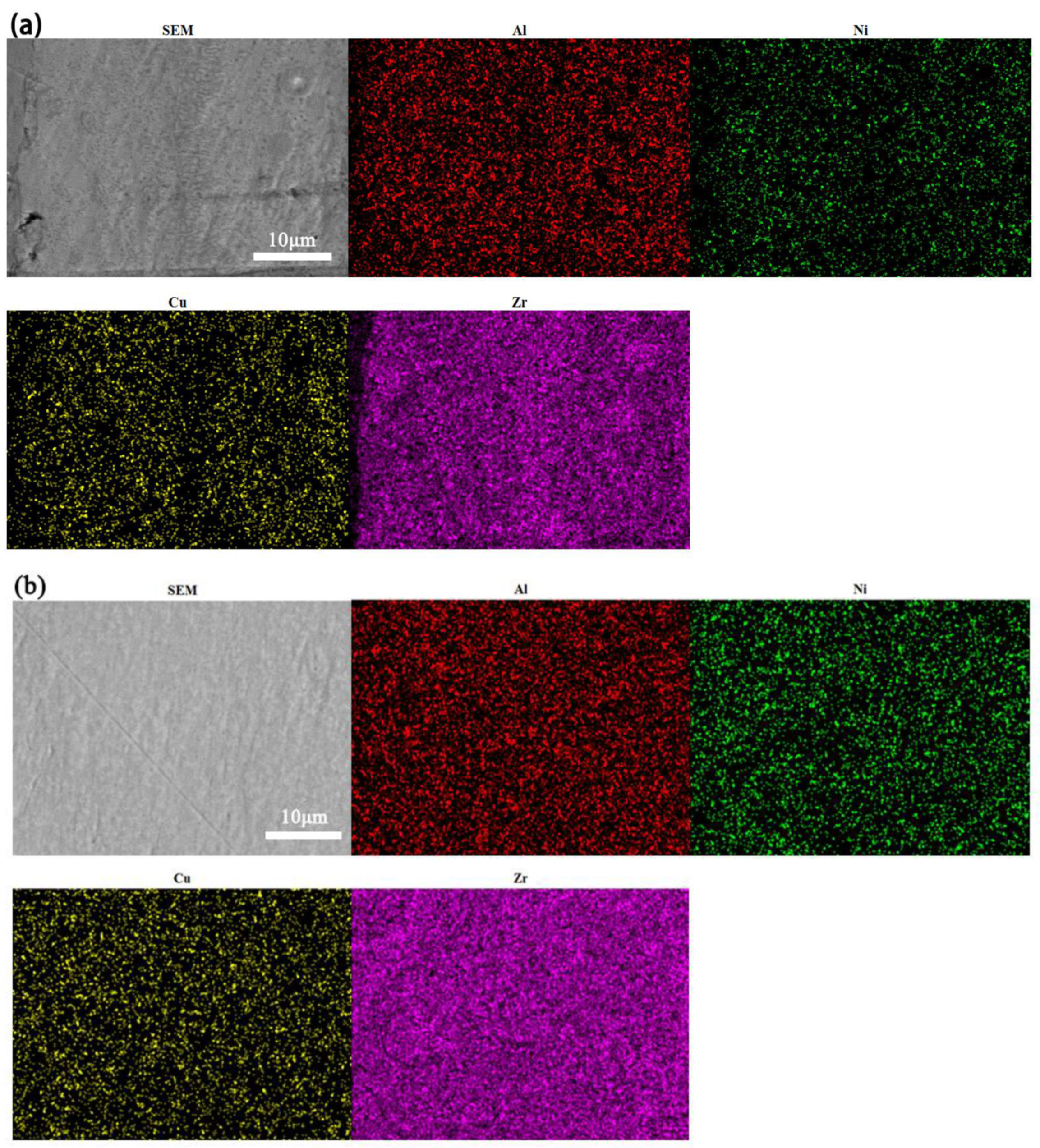
Figure 4. It can be seen from the figure that the CP cladding layer is well bonded with the AISI 1045 steel matrix, and the bonding between the AP cladding layer and the substrate is poor. The cladding thickness of the two samples is about 400 μm, and the amorphous powder cladding layer is thicker. Observing the sample from the figure, there are many small holes distributed on the AP cladding layer, while the CP cladding layer shows a smooth and non-porous state, so the CP cladding layer should be relatively dense. The distribution of elements on the cross section of CP and AP cladding layers (Figure 5) shows that Zr, Cu, Ni and Al elements are uniformly distributed in CP cladding layer, but a little unevenly distributed in AP cladding layer. This may be related to the formation of a large amount of enthalpy and surface activity of the amorphous alloy powder during the mechanical alloying preparation process. It is reported that [18,19] the heat enthalpy and surface activity of the AP prepared by ball milling make it easier for atoms to overcome the potential barrier and form lower crystallization activation energy, and lower the glass transition point and melting point. Some literature points out that [20] the high-energy laser beam interacts with the substance, releasing a large amount of heat instantly to melt the substance quickly. Compared with the CP, the AP can quickly melt to form a cladding layer with only a small amount of external energy due to its own enthalpy and surface activity. The energy density of high-energy laser beam is high, the amorphous powder in the laser beam high-speed scanning, the instantaneous release of heat, through the heat transfer to the matrix more heat, the molten pool often produces gas turbulence, which makes the molten metal easier to flip, gas overflow from the molten pool, forming a large number of small holes and thick cladding layer. In the process of laser irradiation, laser energy is absorbed to form molten metal, and the heat transferred to the matrix is less than that of amorphous powder. The melting process and cooling process are more stable than the melting process of amorphous powder. The formed cladding layer is easier to be dense, with fewer small holes, and the thickness of cladding layer is correspondingly thinner.
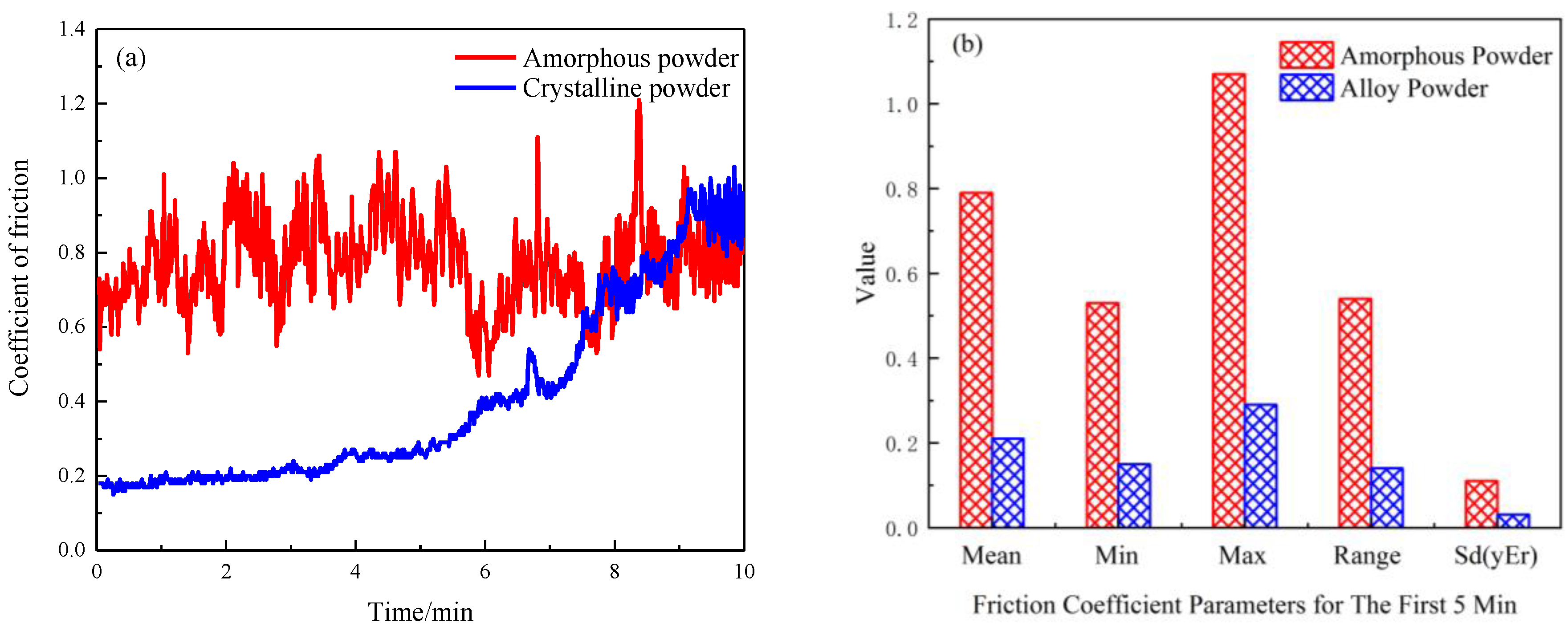
The friction coefficient curve of AP and crystalline powder cladding sample is shown in Figure 6a. It can be seen from Figure 6a that during the friction and wear experiment, the friction coefficient of the amorphous powder cladding layer mainly fluctuates between 0.5 and 1, and the fluctuation range is very large. The maximum instantaneous friction coefficient is 1.21, and the minimum instantaneous friction coefficient is also higher than 0.45. The overall friction coefficient of the CP cladding layer is relatively smooth, and with time increases, the friction coefficient shows a gradually increasing trend. In the first 5 min, the maximum instantaneous friction coefficient of AP cladding layer and CP cladding layer is 1.07 and 0.29, the minimum instantaneous friction coefficient is 0.53 and 0.15, the average friction coefficient is 0.79 and 0.21, and the maximum amplitude of friction coefficient is 0.54 and 0.14, respectively, as shown in 
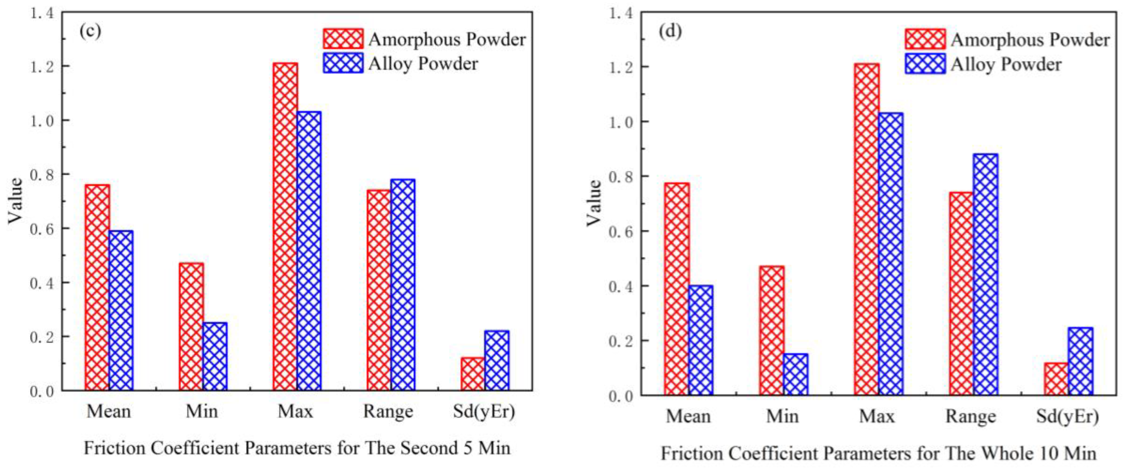
Figure 6b. At this stage, the friction performance parameters of the CP cladding layer are significantly better than those of the AP cladding layer. In the last 5 min, the maximum instantaneous coefficient of friction of AP cladding and CP cladding is 1.21 and 1.03, the minimum instantaneous coefficient of friction is 0.47 and 0.25, the average coefficient of friction is 0.79 and 0.59, and the maximum amplitude of friction coefficient is 0.74 and 0.78, respectively, as shown in Figure 6c. At this stage, the friction performance parameters of the CP cladding layer quickly lose their advantages with the increase of time, and some parameter values are worse than those of the AP cladding layer. During the entire friction and wear experiment, the maximum instantaneous friction coefficients of the AP cladding layer and CP cladding layer were 1.21 and 1.03, the minimum instantaneous friction coefficients were 0.47 and 0.15, and the average friction coefficients were 0.77 and 0.40, respectively. The maximum amplitudes of the coefficients are 0.74 and 0.88, respectively, as shown in Figure 6d. The above data consolidation is shown in Table 5.
Overall, the friction performance of the CP cladding layer is better than that of the AP cladding layer. In the final stage of the experiment, the friction performance gap between the two gradually became smaller, and even showed the opposite result, which may be related to the surface cladding layer being worn through and losing the strengthening effect.
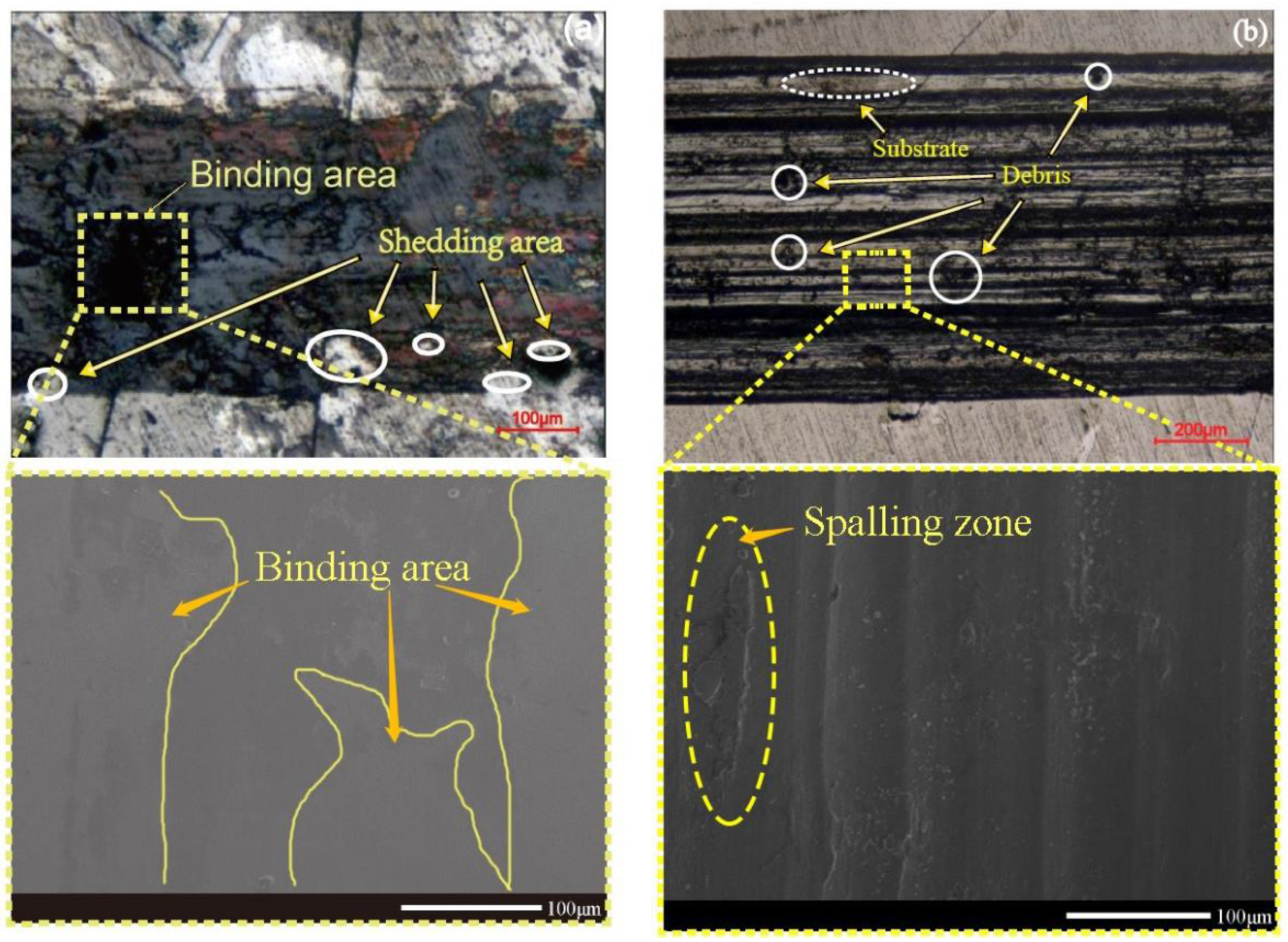
The micro morphology of wear marks of AP cladding layer and CP cladding layer after friction and wear is shown in Figure 7, in which Figure 7a is the wear mark of amorphous cladding layer and Figure 7b is the wear mark of CP cladding layer. The wear scar width of the amorphous powder cladding layer is about 330 μm, and the wear scar width of the alloy powder cladding layer is about 740 μm. Under the same test conditions, the wider the wear scar, the greater the amount of wear. Therefore, the wear amount of the amorphous powder cladding layer in this test is smaller. It can be seen from Figure 7a that the part of the edge of the wear scar of the amorphous cladding layer is partially peeled off, which is related to the rapid and violent melting of the AP under the energy density of the high-energy laser beam and the insufficient bonding of some areas of the cladding layer; Binding area appears in the wear scar. The binding area is caused by local welding and subsequent sliding shear caused by pressure generated in the individual contact area between the GCr15 steel ball and the surface of the cladding layer during the friction test. In Figure 7b, no bonding zone is observed in the wear scar of CP coating, but there are debris and spalling zones. In the process of sliding friction, the GCr15 steel ball and the cladding layer have a slight bite, and then the surface layer is torn out, thus forming spalling zones. Compared with the wear marks of the AP cladding layer, the wear marks of the CP cladding layer show obvious furrow morphology, and part of the substrate is exposed due to the severe wear of the cladding layer, which may be the reason for the sharp rise of the friction coefficient of the CP cladding layer in the later stage of the friction and wear experiment.
Figure 8 shows the distribution of the microhardness of the two cladding samples compared with AISI 1045 steel. It can be seen from Figure 8a that the microhardness of the AP cladding layer and the CP cladding layer is significantly higher than that of the AISI 1045 steel substrate. The surface microhardness of the two cladding samples reached the maximum values of 1322 and 661 Hv, respectively. As the depth increases, the microhardness values of the two cladding samples gradually decrease. Within 300 μm from the surface, the microhardness of the AP cladding layer decreases more rapidly with the increase in depth, and the microhardness is significantly higher than that of the CP cladding layer. Starting at about 400 μm from the surface, the micro-hardness of the two slowly decreases and approaches as the depth increases further. Beyond 700 μm, with the further increase of depth, the microhardness values of the two materials gradually approach 282 Hv, which can be determined as the microhardness value of 45 steel matrix. The surface microhardness of laser cladding layer of AP is increased by 369% compared with that of AISI 1045 steel matrix, and the mean value of microhardness (MV) of the whole cladding layer is 984 Hv, which is 3.5 times of that of AISI 1045 steel matrix. The average microhardness of the cladding layer is 508 Hv, which is 2.3 and 1.8 times of that of the AISI 1045 steel matrix, respectively. The surface microhardness and average microhardness of cladding layer of AP cladding sample are 49% and 94% higher than that of CP cladding sample respectively, which shows great advantage of hardness modification. The microhardness of AP cladding sample and CP cladding sample in powder remelting zone (PRZ), junction zone (JZ) and basic matrix (BM) are 950, 523, 282 and 604, 311 and 282, respectively, as shown in Figure 8b. From the point of view of hardness, the overall hardness of the AP cladding layer is higher than that of the CP modified layer, and the modification effect is very significant.
In this experiment, compared with the CP cladding layer, the AP cladding layer is less dense, with a large number of fine holes, and the thickness of the cladding layer is slightly larger, which is related to the higher activity and enthalpy of the amorphous powder. Reactivity and enthalpy cause the AP cladding layer to have a more violent melting reaction than CP at the same laser energy input, and the heat transport distance is longer. Although the surface microhardness and average microhardness of the AP cladding layer are significantly higher than those of the CP cladding layer, in the friction and wear process, the friction coefficient is large and the friction performance is poor, which contradicts the results of general conventional friction experiments [21]. In fact, in the friction wear experiment, the AP cladding sample is much harder than the CP cladding sample, but the former is distributed with a large number of small holes inside, so that the GCr15 steel ball in the test constantly ups and downs, friction test stability relative to the alloy powder cladding is poor, resulting in violent fluctuations in the coefficient of friction. The CP cladding layer is denser, there are no or a few tiny holes inside, the friction test stability is better, and the friction coefficient is small. Near the end of the frictional wear experiment, the cladding layer was first worn because the hardness and thickness of the CP cladding were smaller than the AP cladding layer. At this time, the force of the friction pair steel ball on the sample is significantly enhanced, resulting in a furrow-like appearance in the wear scar of the CP cladding layer. The intensification of wear leads to widening of the wear scar, and finally the width of the wear scar of the CP cladding layer is larger than that of the AP cladding layer. Due to the extremely high microhardness and thickness of the AP cladding layer, it was not worn through at the end of the experiment, showing a smoother wear scar morphology and a narrower wear scar width. If the AP cladding layer can avoid defects such as porous holes, the AP cladding layer will have more room for performance improvement than the CP cladding layer. It can be predicted that by optimizing the laser irradiation process parameters, appropriately reducing the energy flow density and increasing the pulse width, and taking measures such as protective atmosphere, it is very possible to obtain a less-holes AP cladding modified layer and obtain better overall performance.

4. Conclusions

This article attempts to prepare different types of cladding layers by laser cladding modification technology, and explore ways and methods for strengthening the surface of AISI 1045 steel to expand its application range. The conclusions are as follows: The thickness of the cladding layer is about 400 μm, and the thickness of the amorphous powder (AP) cladding layer is slightly larger than that of the crystalline powder (CP) cladding layer. There are many holes in the AP cladding layer, and holes can be observed at the junction with the matrix; while the CP cladding layer is well combined with the matrix and no holes are observed. The friction performance of the CP cladding layer is better than that of the AP cladding layer. The wear scar of the AP cladding layer has a bonding zone, whereas the wear scar of the CP cladding layer has a furrow-like morphology, and there is no bonding zone, and there is a part of the matrix in the wear scar exposed. The surface microhardness of the AP cladding layer and the average microhardness of the cladding layer are 49% and 94% higher than those of the CP cladding layer, respectively. The microhardness of AP cladding samples and CP cladding samples power remelting zone (PRZ), junction zone (JZ) and basic matrix (BM) are 950, 523, 282 and 604, 311, 282, respectively. From the perspective of hardness only, the overall hardness of the amorphous powder cladding layer is greater than the crystalline powder modified layer, and the modification effect is very significant.

Author Contributions

Y.C. and P.T. designed the study; Y.C., W.Z., C.Z., and K.Z. performed the measurements processed experimental data; Y.C. and P.T. wrote most of the initial versions of the text. All authors contributed to research strategy, the discussion and interpretation of the results and to the final form of the text and figures. All authors have read and agreed to the published version of the manuscript.

Funding

This research was funded by the Applied Science and Technology Research Project of Guangdong Province (2015B010127003), the Guangzhou Science and Technology Project (201607010052, 201807010012), the 2019 Guangdong Province Science and Technology Special Fund (“Big Special Project + Task List” Management Mode) Funded Project (2019dzx025) of Qingyuan City, the National Natural Science Foundation of China (51735003), the foundation and application foundation team project of Guangdong Province (2019BT02C629), and the Project of Guangdong Academy of Sciences (2020GDASYL-20200402005).

Institutional Review Board Statement

Not applicable.

Informed Consent Statement

Not applicable.

Data Availability Statement

Data is contained within the article.

Acknowledgments

Thanks to Zhenghua Huang from Guangdong Institute of materials and processing for the convenience in sample preparation.

Conflicts of Interest

The authors declare no conflict of interest. The funders had no role in the design of the study; in the collection, analyses, or interpretation of data; in the writing of the manuscript, or in the decision to publish the results.

References

  1. Lu, Y.; Huang, G.; Wang, Y. Crack-free Fe-based amorphous coating synthesized by laser cladding. Mater. Lett. 2018, 210, 46–50. [Google Scholar] [CrossRef]
  2. Nie, X.P.; Xu, X.M.; Jiang, Q.K. Effect of microalloying of Nb on corrosion resistance and thermal stability of ZrCu-based bulk metallic glasses. J. Non Cryst. Solids. 2009, 355, 203–207. [Google Scholar] [CrossRef]
  3. Guo, S.F.; Zhang, H.J.; Liu, Z. Corrosion resistances of amorphous and crystalline Zr-based alloys in simulated seawater. Electrochem. Commun. 2012, 24, 39–42. [Google Scholar] [CrossRef]
  4. Raju, V.R.; Kühn, U.; Wolff, U. Corrosion behaviour of Zr-based bulk glass-forming alloys containing Nb or Ti. Mater. Lett. 2002, 57, 173–177. [Google Scholar] [CrossRef]
  5. Zander, D.; Köster, U. Corrosion of amorphous and nanocrystalline Zr-based alloys. Mater. Sci. Eng. A 2004, 375, 53–59. [Google Scholar] [CrossRef]
  6. Inoue, A. Stabilization of metallic supercooled liquid and bulk amorphous alloys. Acta Mater. 2000, 48, 279–306. [Google Scholar] [CrossRef]
  7. Liu, W.; Hou, Y.; Liu, C. Hot corrosion behavior of a centimeter Fe-based amorphous composite coating prepared by laser cladding in molten Na2SO4+ K2SO4 salts. Surf. Coat. Technol. 2015, 270, 33–38. [Google Scholar] [CrossRef]
  8. Shu, F.; Tian, Z.; Zhao, H. Synthesis of amorphous coating by laser cladding multi-layer Co-based self-fluxed alloy powder. Mater. Lett. 2016, 176, 306–309. [Google Scholar] [CrossRef]
  9. Hashimoto, K.; Kumagai, N.; Yoshioka, H. Corrosion-resistant amorphous surface alloys. Corros. Sci. 1993, 35, 363–370. [Google Scholar] [CrossRef]
  10. Inoue, A.; Zhang, T.; Masumoto, T. Glass-forming ability of alloys. J. Non Cryst. 1993, 156, 473–480. [Google Scholar] [CrossRef]
  11. Xu, Y.K.; Xu, J. Ceramics particulate reinforced Mg65Cu20Zn5Y10 bulk metallic glass composites. Scr. Mater. 2003, 49, 843–848. [Google Scholar] [CrossRef]
  12. Sun, W.S.; Quan, M.X. Hardening behavior of amorphous alloy Al90RE5Ni5 dispersion by nanoscale α-Al during crystallization. Mater. Lett. 1996, 27, 101–105. [Google Scholar] [CrossRef]
  13. Greer, A.L. Partially or fully devitrified alloys for mechanical properties. Mater. Sci. Eng. A 2001, 304–306, 68–72. [Google Scholar] [CrossRef]
  14. Audebert, F.; Colaço, R.; Vilar, R. Production of glassy metallic layers by laser surface treatment. Scr. Mater. 2003, 48, 281–286. [Google Scholar] [CrossRef]
  15. Subramanian, R.; Sircar, S.; Mazumder, J. Laser cladding of zirconium on magnesium for improved corrosion properties. J. Mater. Sci. 1991, 26, 951–956. [Google Scholar] [CrossRef]
  16. Yue, T.M.; Su, Y.P.; Yang, H.O. Laser cladding of Zr65Al7.5Ni10Cu17.5 amorphous alloy on magnesium. Mater. Lett. 2007, 61, 209–212. [Google Scholar] [CrossRef]
  17. Yue, T.M.; Su, Y.P. Laser multi-layer cladding of Zr65Al7.5Ni10Cu17.5 amorphous alloy on magnesium substrates. J. Mater. Sci. 2007, 42, 6153–6160. [Google Scholar] [CrossRef]
  18. Zaluski, L.; Zaluska, A.; Strom-Olsen, J.O. Hydrogen absorption in nanocrystalline Mg2Ni formed by mechanical alloying. J. Alloys Compd. 1995, 217, 245–249. [Google Scholar] [CrossRef]
  19. Zhang, X.S.; Ran, G. Review of the Reactive Mechanism in Mechanical Alloying. Heat. Treat. Met. 2003, 6, 28–32. [Google Scholar]
  20. Li, N.; Zhang, J.; Xing, W. 3D printing of Fe-based bulk metallic glass composites with combined high strength and fracture toughness. Mater. Des. 2018, 143, 285–296. [Google Scholar] [CrossRef]
  21. Hua, N.; Liao, Z.; Chen, W. Effects of noble elements on the glass-forming ability, mechanical property, electrochemical behavior and tribocorrosion resistance of Ni-and Cu-free Zr-Al-Co bulk metallic glass. J. Alloys Compd. 2017, 725, 403–414. [Google Scholar] [CrossRef]
Figure 1. The schematic diagram of the sample preparation process.
Coatings 11 00103 g001
Figure 2. XRD patterns of crystalline powder and amorphous alloy powder.
Coatings 11 00103 g002
Figure 3. (a) A sample with amorphous powder cladding layer. (b) A sample with crystalline powder coating.
Coatings 11 00103 g003
Figure 4. (a) A profile of amorphous powder cladding layer. (b) A profile of crystalline powder cladding layer.
Coatings 11 00103 g004
Figure 5. (a) The distribution of elements in the cross-section of amorphous alloy cladding layer. (b) The distribution of elements in the cross-section of crystalline powder cladding layer.
Coatings 11 00103 g005
Figure 6. (a) Curve of friction coefficient of amorphous alloy powder and crystalline powder cladding sample; (b) Parameters of friction coefficient for the first five minutes; (c) Parameters of friction coefficient for the last five minutes; (d) Parameters of friction coefficient for the whole ten minutes.
Coatings 11 00103 g006aCoatings 11 00103 g006b
Figure 7. (a) A wear mark of amorphous powder cladding layer; (b) A wear mark of crystalline powder cladding layer.
Coatings 11 00103 g007
Figure 8. The distribution of the microhardness of the two cladding samples compared with AISI 1045 steel. (a) Microhardness curve of the two cladding samples; (b) Histogram of average microhardness in basic matrix, junction zone, powder remelting zone and mean value of the two cladding samples.
Coatings 11 00103 g008
Table 1. The parameters of ball milling.
ParametersValue
Ball milling medium: ethanol absolute2 mL
Ball milling time15 h
Ball mill speed350 r/min
Ball to material ratio20:1
Table 2. The chemical composition of AISI 1045 steel.
ElementsContent
Fe98.50–98.96
C0.43–0.50
Mn0.60–0.90
P≤0.040
S≤0.050
Table 3. Parameters of laser cladding.
ParametersValue
Pulse current (A)130
Laser frequency (Hz)14
Pulse duration (ms)1.5
Scanning speed (mm/s)4
Spot size (mm)4
Overlapping50%
Table 4. Parameters of friction and wear.
ParametersValue
GCr15 steel ball diameter (mm)3
Load (N)5
Linear reciprocating friction length (mm)3
Friction time (min)10
Sliding speed (mm/min)200
Roughness of GCr15 steel ballRa0.1
Table 5. Data of friction coefficient.
TimeSamplesMaximum Friction CoefficientMinimum Friction CoefficientAverage Friction CoefficientMaximum Amplitude of Friction Coefficient
First 5 minCP0.290.150.210.14
AP1.070.530.790.54
Last 5 minCP1.030.250.590.78
AP1.210.470.790.74
Whole 10 minCP1.030.150.400.88
AP1.210.470.770.74
Publisher’s Note: MDPI stays neutral with regard to jurisdictional claims in published maps and institutional affiliations.

