
Finite Element Analysis of Composite Repair for Damaged Steel Pipeline


1
Department of Civil Engineering, Central South University, Changsha 410075, China
2
Department of Civil and Environmental Engineering, Rutgers, The State University of New Jersey, Piscataway, NJ 08854, USA
*
Author to whom correspondence should be addressed.
Coatings 2021, 11(3), 301; https://0-doi-org.brum.beds.ac.uk/10.3390/coatings11030301
Submission received: 31 December 2020
/
Revised: 26 February 2021
/
Accepted: 2 March 2021
/
Published: 5 March 2021
Abstract
:Carbon fiber reinforced polymer (CFRP) matrix composite overwrap repair systems have been introduced and accepted as an alternative repair system for steel pipeline. This paper aimed to evaluate the mechanical behavior of damaged steel pipeline with CFRP repair using finite element (FE) analysis. Two different repair strategies, namely wrap repair and patch repair, were considered. The mechanical responses of pipeline with the composite repair system under the maximum allowable operating pressure (MAOP) was analyzed using the validated FE models. The design parameters of the CFRP repair system were analyzed, including patch/wrap size and thickness, defect size, interface bonding, and the material properties of the infill material. The results show that both the stress in the pipe wall and CFRP could be reduced by using a thicker CFRP. With the increase in patch size in the hoop direction, the maximum von Mises stress in the pipe wall generally decreased as the maximum hoop stress in the CFRP increased. The reinforcement of the CFRP repair system could be enhanced by using infill material with a higher elastic modulus. The CFRP patch tended to cause higher interface shear stress than CFRP wrap, but the shear stress could be reduced by using a thicker CFRP. Compared with the fully bonded condition, the frictional interface causes a decrease in hoop stress in the CFRP but an increase in von Mises stress in the steel. The study results indicate the feasibility of composite repair for damaged steel pipeline.
1. Introduction
The pipeline system is one of the most capital-intensive infrastructure systems. Recent investigations of pipeline performance have shown that one of the primary reasons for pipeline failure is corrosion [1,2]. Common types of corrosion that may occur in practice include uniform corrosion, pitting corrosion, crevice corrosion, and galvanic corrosion [3]. Numerous studies have been conducted to evaluate the corrosion damage based on physical, empirical, and numerical models [4,5,6,7,8]. The metal loss caused by corrosion not only leads to stress concentration in the pipe wall but also causes corrosion fatigue [9,10,11]. The corroded segment should either be replaced or repaired if the safe operation of the pipeline system cannot be maintained. In most cases, the replacement of the pipeline segment is costly and time-consuming; thus, to repair the damaged pipeline is usually the preferred option [12].
Conventionally, the in-service corroded pipelines are repaired with the external sleeve-repair welding technique, in which the damaged segments are cut off and replaced with new substitution [13,14]. At present, full encirclement steel sleeves, welded leak boxes, and steel mechanical clamps are widely used. However, there are some concerns associated with the above repair methods, including pipe wall melting, high residual stresses, and hydrogen-assisted cracking [15,16,17]. In order to overcome these defects, an alternative in-service repair strategy, namely, fiber-reinforced polymer (FRP) composite repair systems, have been reported in the literatures [18,19,20,21,22,23]. In the FRP composite repair systems, the external defects on the pipe wall are filled with grouts, such as epoxy resins, and then coiled with layers of FRP sleeves using interlayer adhesive. The FRP repair system offers various advantages. First, it requires shorter time and lower maintenance cost. Second, the integrity of the pipeline is ensured during the rehabilitation process so that the pipelines can continue to operate with no leakage. Third, the potential risk of explosion is eliminated and, finally, the corrosion process is slowed [24,25,26].
In order to understand the behavior of the pipelines repaired with the FRP composite repair systems, several studies have been conducted based on analytical, experimental, and finite element (FE) methods [27,28,29,30,31]. In some recent developments of standards, the application of FRP composite repair systems has been gradually accepted [32]. Currently, most of the FRP composite repair systems are based on the wrap repair strategy. However, since the defect geometry has significant impact on the remaining strength of corroded pipeline [33], the full wrap repair strategy could be excessive for some small and shallow defects. In this case, the application of patch repair could be feasible. Moreover, with a pre-cured FRP patch, the time consumption for the repair could be further reduced. Theisen and Keller [34] conducted finite element simulation and experimental tests for both patch and wrap repairs on through-wall defects. The simulation showed that the max strain of patch was slightly higher than the one of wrap type. Ayaz et al. studied the composite patch repair for a small through-wall hole. The results showed that the increment in overlap length could enhance the failure strength [35]. In general, the FRP patch repair strategy is mainly used for small-area through-wall defects at present. However, corrosion is a gradual deterioration process, and the pipe may fail due to internal pressure even when the defect in the pipe wall is shallow. The load transfer mechanism and mechanical behavior of the FRP patch repair under this condition remain unclear.
2. Objectives
The primary objective of this study is to develop 3D FE models that can evaluate the mechanical behavior of the pipeline with carbon fiber reinforced polymer (CFRP) composite repair systems. Two different repair strategies, namely CFRP wrap repair and CFRP patch repair, were considered. The mechanical behavior of the pipeline with the CFRP repair system under both the burst pressure and the maximum allowable operating pressure (MAOP) was analyzed. The presented model was validated with existing experimental data of burst pressure. A lap shear test was conducted to evaluate shear bonding strength between the CFRP and the pipe. With the presented model, various parameters for the design of CFRP repair system were analyzed, including the CFRP patch/wrap size and thickness, defect size, interface property, and the material properties of the infill material.
3. Development of FE Model
3.1. Model Dimensions and Meshes
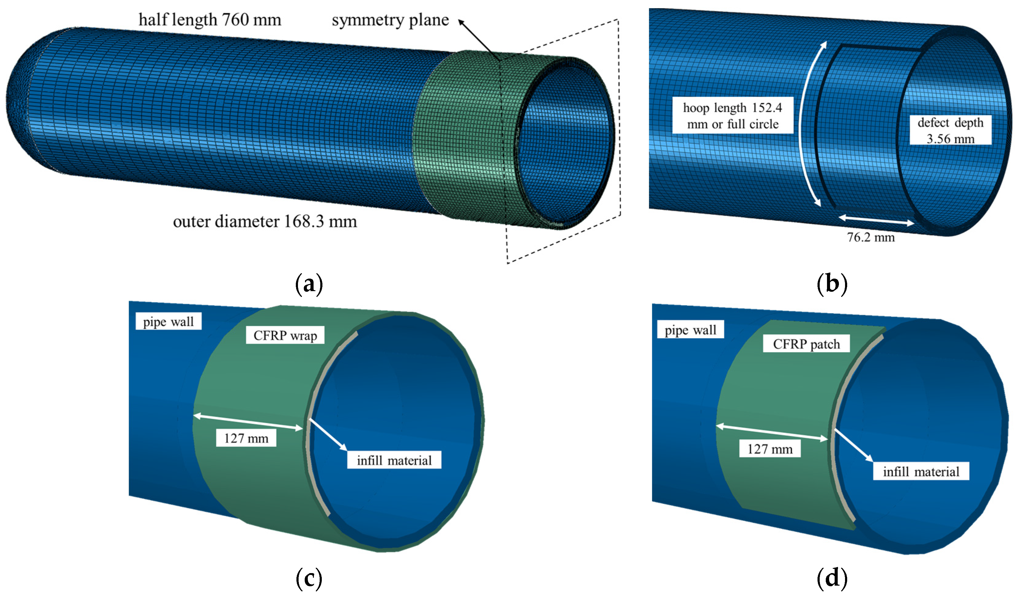
The 3D FE model was developed with commercial software ABAQUS (v6.12). The dimensions of the pipeline segment model are shown in Figure 1. The outer diameter and length of the steel pipe were 168.3 and 1520 mm, respectively. The thickness of steel wall was 7.11 mm. In the symmetrical model, the half-length of the steel pipe was 760 mm, and the symmetric boundary condition was applied to reduce the computational cost. Different-sized defects in the steel pipe wall were simulated to represent for the metal loss due to corrosion, as shown in Figure 1b. The depth in the radial direction and the length in the axial direction were 3.56 and 152.4 mm, respectively, for all defects. In the hoop direction, the defect length was either 152.4 mm or equal to the perimeter of the pipe (full circle). In the symmetrical model, the half-length of the defect in the axial direction was 76.2 mm. Two different repair strategies were evaluated in this study. One was wrap repair, and the other was patch repair. For the wrap repair shown in Figure 1c, the defect in the steel pipe wall was filled with repair material (adhesive putty), and then CFRP wraps were applied along the hoop to cover the defect, while for the patch repair shown in Figure 1d, the CFRP was not applied along the hoop but was patched over the defect with a specific length in the hoop direction. It should be noted that the patch repair was only applied to the defect with a hoop length of 152.4 mm since the CFRP patches should be larger than the defect, and different-sized patches were used in the analysis.
In the FE model, the cap of the pipe was meshed with the free meshing technique. The element type was a ten-node quadratic tetrahedron 3D stress element. The other sections, including the pipe wall, infill material, and the CFRP, were meshed with the structured meshing technique. The element type was an eight-node linear brick, reduced integration 3D stress element. To ensure both the computational accuracy and efficiency, the element size in the hoop direction was taken as 4 mm for the pipe, infill material, and the CFRP. The element size in the axial direction was taken as 4 mm for the infill material and the CFRP. Because the length of the pipe was relatively large, the element size in the length direction was gradually changing. In detail, for the pipe, the element size near the defect was smaller, which was taken as 4 mm, while the element size far from the defect was larger (taken as 10 mm). The meshes were refined around the defect area along the axial direction. In the radial direction, the pipe wall and infill material were divided into 16 and 10 layers of elements, respectively. The layers of elements in the radial direction for the CFRP depended on the thickness of the CFRP. In this study, the thickness of the CFRP was either 3.1 or 6.2 mm. The CFRP was divided into 10 layers for the 3.1 mm thickness and 20 layers for the 6.2 mm thickness. In this case, the total number of elements in the pipe and infill material were determined as about 150,000 and 7000, respectively. The total number of elements ranged from about 13,000 to 90,000, depending on the size of the CFRP.
3.2. Material Properties
In this study, ASTM A106 [36] Grade B steel was used for the pipe wall. A linear elastic model was used to define the material property of the steel before yield, while a nonlinear plastic model, as shown in Table 1, was used to define the plastic behavior of the steel. The repair material was the thickened epoxy. The epoxy was modeled with a bilinear elastic stress–strain model, as shown in Table 1. Two different composite thicknesses were considered: 3.1 mm for six layers of CRFP and 6.2 mm for 12 layers of CFRP. The CFRP was modeled as orthotropic linear elastic material, as shown in Table 1.
3.3. Model Validation
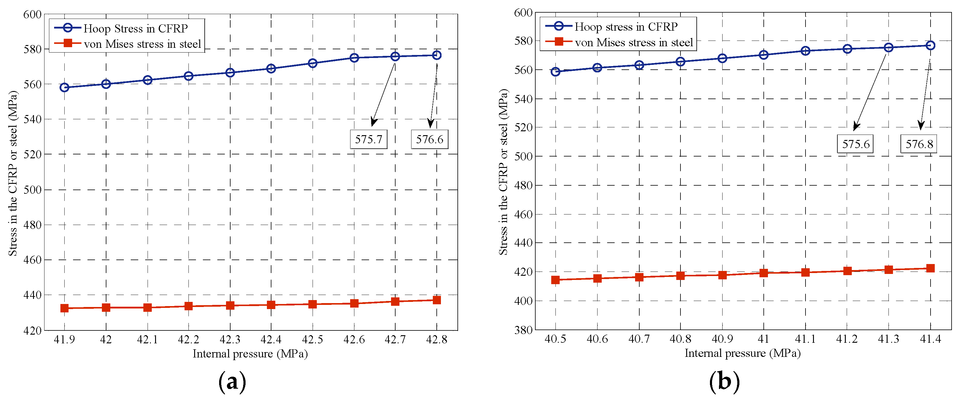
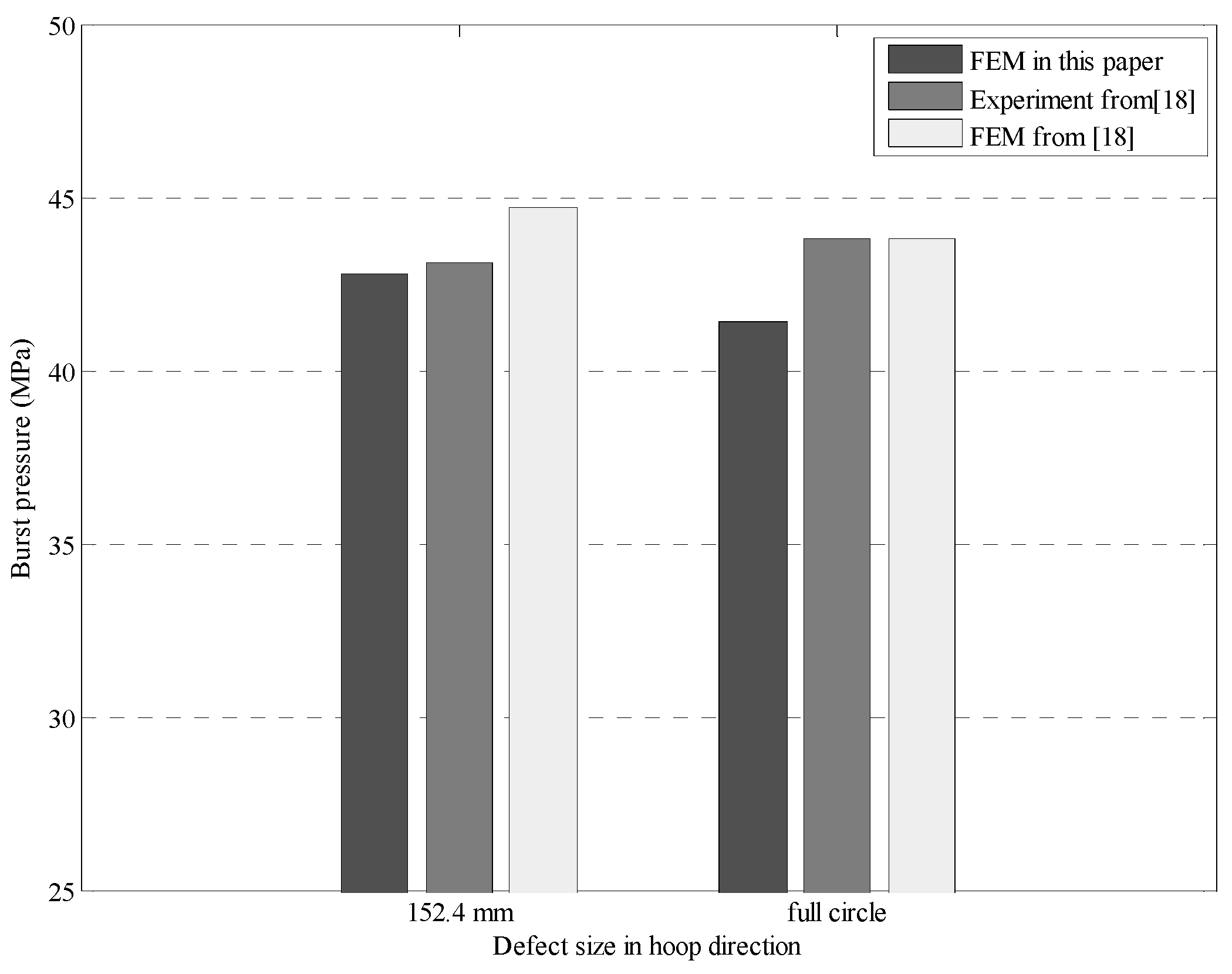
In order to validate the FE model in this study, the burst pressure calculated with the FE model in this paper was compared with the experimental data reported in the literature [18]. In the validation step, the CFRP wrap repair was used, and the thickness of the CFRP was 3.1 mm. An air-actuated, hydraulic power unit was used to pressurize the test vessel. The pump forces water into the pressure vessel until rupture occurs. It was assumed that the pipe wall, infill material, and CFRP were bonded tightly, so that no slip was allowed at the interfaces between different materials. The internal pressure was increased from 40 MPa to the burst pressure by 0.1 MPa. The system could be considered as a burst failure when the von Mises equivalent stress in the steel reached the true ultimate tensile strength or when the maximum hoop stress in the CFRP exceeded its ultimate hoop strength. Figure 2 shows the maximum hoop stress in the CFRP and the maximum von Mises stress in the steel under different internal pressure. The simulation results show that the hoop stress in the CFRP exceeded its ultimate hoop strength (576 MPa) before the von Mises equivalent stress in the steel reached the true ultimate tensile strength (648 MPa). The burst pressure predicted with the FE model in this paper is shown in Figure 3, together with the experimental and numerical data reported in the literature [18]. The relative difference between the predicted and experimental value is 0.69% for the pipe with a 152.4 mm defect in the hoop direction, and it is 5.48% for the pipe with a full-circle defect in the hoop direction. Although the causes of the above relative error may be multiple, such as complex contact conditions between steel, CFRP and infill materials, in general, the accuracy of the FE model developed in this paper is acceptable.
4. Analysis of CFRP Repair on Pipeline Stress
4.1. Determination of MAOP
In most cases, the internal pressure of the pipeline is much lower than the burst pressure of the sound pipeline. Therefore, in the following analysis, the maximum allowable operating pressure (MAOP) was used instead of the burst pressure. In practice, the MAOP cannot exceed the lowest value of the design pressure, test pressure, the maximum operating pressure during the 5 years preceding applicable date, and the maximum safe pressure determined by the operator. In this study, the design pressure was used to determine the MAOP, since the design pressure can be simply determined with Barlow’s formula, as shown in Equation (1):
where P is the design pressure; S is the yield strength of steel; t is the nominal wall thickness of the pipe; D is the outside diameter of the pipe; F is the design factor, equaling 0.72 for liquid pipeline and Class 1 gas pipeline; E is the longitudinal joint factor; T is the temperature factor.
For the pipeline used in this study, the design pressure could be calculated as 18.25 MPa based on Equation (1). As mentioned in the previous section, the CFRP patch repair could not be applied to the full-circle defect since the CFRP patches should be larger than the defect. Therefore, the following discussion was only focused on the defect with a 152.4 mm hoop length.
4.2. Effect of CFRP Thickness and Size
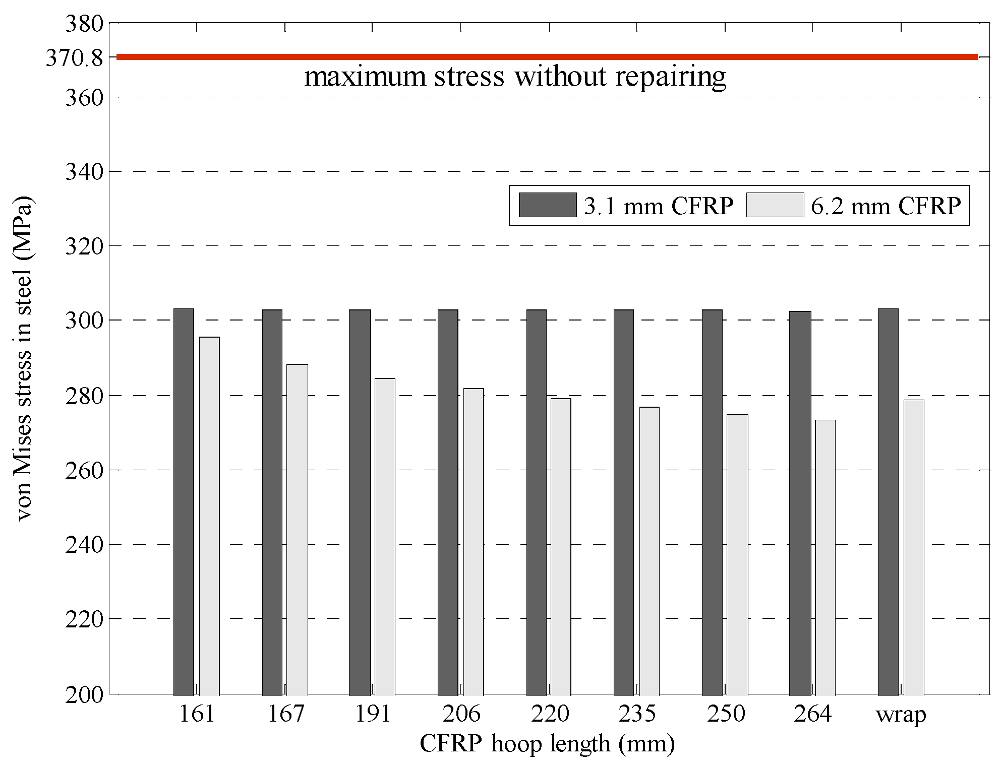
The effects of CFRP thickness and size on the mechanical behavior of the pipeline repair system under the MAOP were analyzed. CFRP patches with two different thicknesses (3.1 and 6.2 mm) in the radial direction were used. The CFRP length in the hoop direction ranged from 161 mm, which was a little larger than the defect, to 264 mm, which equaled half of the pipe perimeter. Despite the CFRP patches, an additional case of CFRP wrap was also developed for comparison. The maximum von Mises stress in the pipe wall and the maximum hoop stress in the CFRP were calculated under the MAOP. Figure 4 shows the maximum von Mises stress in the pipe wall for different cases. As shown in Figure 4, the effect of CFRP size on the maximum von Mises stress was very limited for the 3.1 mm CFRP. A possible reason for this phenomenon is that, for the 3.1 mm CFRP, the maximum von Mises stress in the pipe exceeded the yield strength. In this condition, a relatively small change in stress could lead to a relatively large plastic strain, while for the 6.2 mm CFRP patch, the maximum von Mises stress in the pipe wall generally decreased with the increase in the patch size. This is reasonable since the larger CFRP could provide a larger contact area between the CFRP and the pipe, which enhanced the bonding effect of the repair system. When the 6.2 mm CFRP patch was larger than 235 mm in the hoop direction, the von Mises stress in the steel pipe repaired with CFRP patch could be smaller than that repaired with CFRP wrap. This indicates that it is feasible to use CFRP patch instead of CFRP wrap in proper conditions. Moreover, under the MAOP, the 6.2 mm CFRP patches provided reliable reinforcement since the maximum von Mises stress in the pipe wall was controlled below the yield strength. However, for the 3.1 mm CFRP, the maximum von Mises stress in the pipe wall exceeded the yield strength, indicating there was a risk of failure when the CFRP was too thin. Therefore, compared with the CFRP length in the hoop direction, CFRP thickness is more critical for avoiding failure of the repair system. When the MAOP cannot be reduced, the CFRP thickness should be adequate.
Figure 5 shows the maximum hoop stress in the CFRP for different cases. As shown in Figure 5, for the 6.2 mm CFRP, with the increase in patch size in the hoop direction, the maximum hoop stress in the CFRP increased but was always smaller than that in the CFRP wrap. This indicates that more stress could be transferred to the CFRP when the patch size was larger, while for the 3.1 mm CFRP, larger hoop stress could be observed in the larger CFRP patches. However, the hoop stress in the CFRP wrap could be smaller than that in the CFRP patch. A possible reason for this phenomenon is that the volume of CFRP in the wrap was more than that in the patches; therefore, although more stress could be transferred to the CFRP wrap, the maximum hoop stress could be reduced since the stress could be carried by more CFRP. Similarly, it can be seen from Figure 5 that since the 6.2 mm CFRP could provide more volume to carry the stress, the maximum hoop stress in the 6.2 mm CFRP was always smaller than that in the 3.1 mm CFRP.
4.3. Effect of Modulus of Infill Material
In the composite repair system, the stress is mainly carried by the pipe wall and the CFRP, while the infill material is used as barrier between CFRP and pipeline steel to prevent carbon-induced corrosion of steel while benefiting from the light weight and high strength of carbon fiber. The infill material is usually a polymer material with relatively lower elastic modulus, such as epoxy. However, as an intermediate layer between the pipe wall and CFRP, the modulus of the infill material could have an effect on the load transfer mechanism in the repair system. An inorganic composite that was previously developed for protective coating applications was used as an alternative infill material. The elastic modulus of the inorganic composite can range from 10 to 20 GPa depending on the chemical composition and polymerization process [37]. The effect of infill material modulus on the performance of the CFRP composite repair system is analyzed in this section.
The effect of the infill modulus on the mechanical behavior of the pipeline repair system under the MAOP was analyzed. The CFRP with a thickness of 3.1 mm was not used in this section since the pipe wall may yield under the MAOP based on the previous analysis. The CFRP thickness was 6.2 mm. The maximum von Mises stress in the pipe wall and the maximum hoop stress in the CFRP for repair systems with different infill materials are shown in Figure 6. It can be observed that for any given CFRP size, the von Mises stress in the steel pipe repaired with the 10 GPa-inorganic composite was greater than that repaired with the 20 GPa-inorganic composite but smaller than that repaired with epoxy. Thus, the von Mises stress in the steel pipe decreased for all patch sizes with the increase in the elastic modulus of the filling material. Similarly, the hoop stress in the CFRP decreased for all patch sizes with the increase in the elastic modulus of the filling material. This is mainly because by using an infill material with a higher elastic modulus, the strain in the infill material can be reduced under the same stress. As a result, under the same internal pressure, the deformation of the whole repair system could be reduced. This indicates that the reinforcement of the CFRP repair system can be enhanced by using an infill with a higher elastic modulus.
4.4. Effect of Adhesive Thickness
In the previous FE models, the CFRP patches and wraps were assumed to be bonded tightly with the infill and the pipe wall by using a thin adhesive layer whose thickness could be ignored. However, in practice, the thickness of the adhesive layer can vary. It is also possible that extra infill remains on the pipe wall. In this section, the effect of adhesive thickness on the mechanical behavior of the pipeline repair system is investigated. The 6.2 mm CFRP patches and wraps were used to repair the pipe. A layer of adhesive was simulated to bond the CFRP with the infill and the pipe wall. The thickness of the adhesive was either 2 mm or ignorable (zero). Epoxy (1.74 GPa) and the inorganic composite (10 GPa) were used as infills. The modulus of the adhesive layer was assumed to be either 1.74 or 10 GPa.
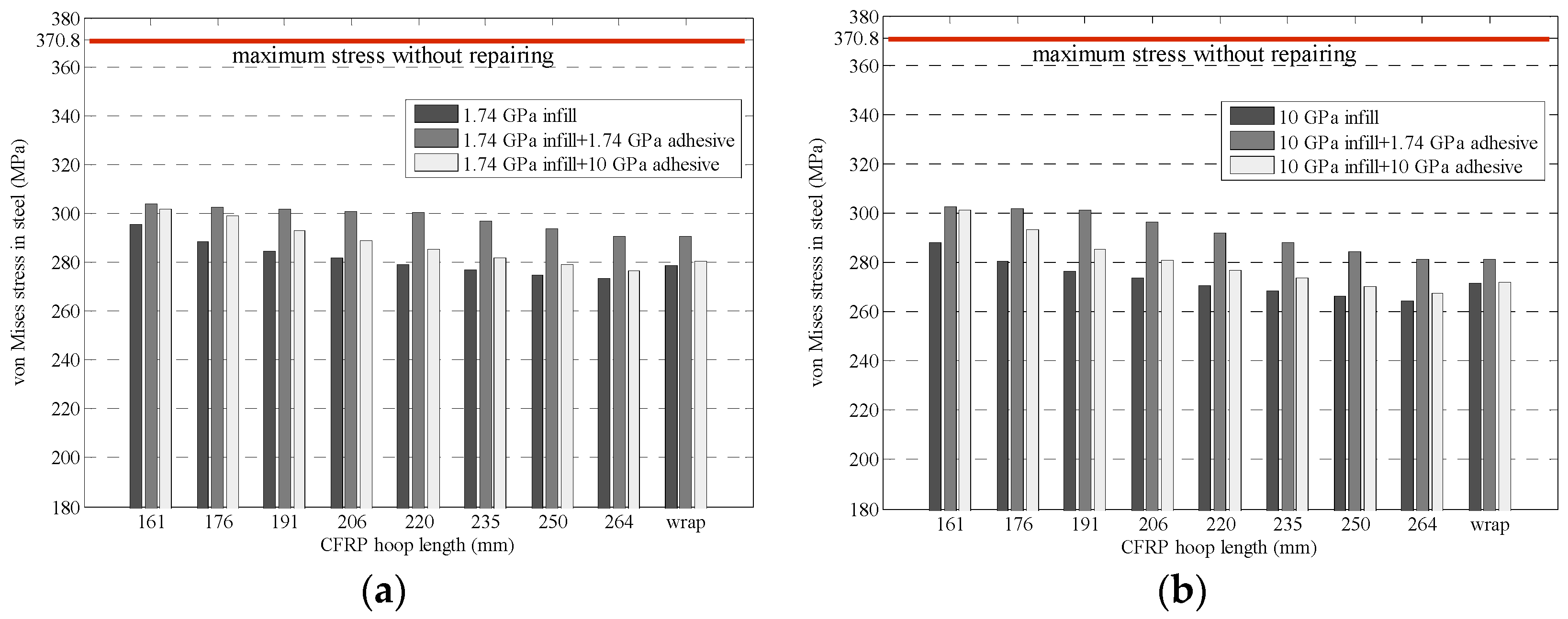
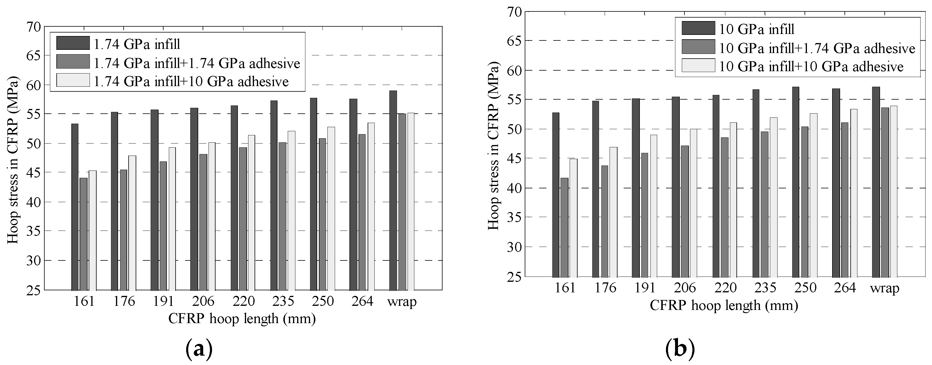
Figure 7 shows the maximum von Mises stress in the pipe wall under the MAOP. It can be observed that with the extra 2 mm adhesive, the maximum von Mises stress in the pipe wall increased for all cases. An opposite trend was observed for the maximum hoop stress in the CFRP, as shown in Figure 8. With the extra 2 mm adhesive, the maximum hoop stress in the CFRP decreased for all cases. This indicates that with the increase in adhesive thickness, the pipe wall carries the higher stress, while the CFRP carries the smaller stress. The main reason for this trend is that the modulus of the adhesive layer is smaller than that of the CFRP and steel pipe. In this case, this adhesive layer could not bear large stress, so the stress from the pipe wall could not be effectively transferred to the CFRP with a thicker adhesive. Therefore, it is not recommended to use more adhesive in the repair system, especially when the corrosion depth is deep. If the extra adhesive cannot be avoided, the resulting adverse effect could be alleviated by using adhesives with higher modulus (e.g., 10 GPa in Figure 7 and Figure 8).
5. Analysis of Bonding Condition between CFRP and Pipe
In the CFRP composite repair systems, the stress is mainly carried by the pipe wall and the CFRP. Therefore, it is important that the bonding strength between pipeline steel and CFRP is high enough to carry the shear stress induced in composite repair. In this section, the bonding condition between the CFRP and pipe wall is analyzed through an experiment and the FE model.
5.1. Shear Bonding Strength Test
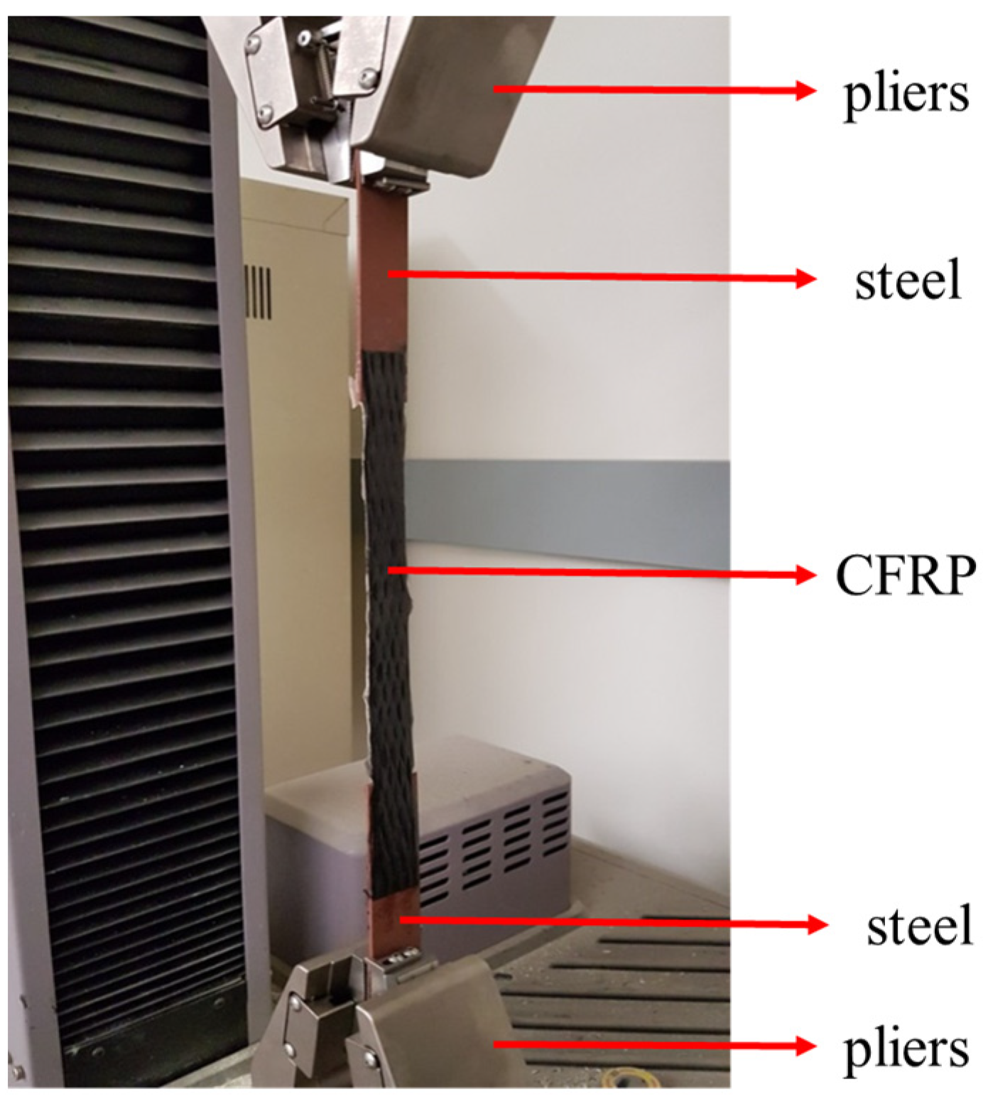
Lap shear tests were conducted to measure the shear bonding strength between the CFRP and steel. The test setup was based on that recommended by ASTM D1002-10 [38], which was modified to include CFRP laminate as the mediator part overlapped with two steel sheets. The overlap length (bond length) on one metal sheet was held to be constant, while the bond length changed on the other steel sheet. This was used to investigate bond failure behavior with changes in bond length on the steel sheet samples. A displacement control tensile loading with a rate of 1.27 mm/min was applied to the specimen until failure occurred. Figure 9 shows the setup for the lap shear test.
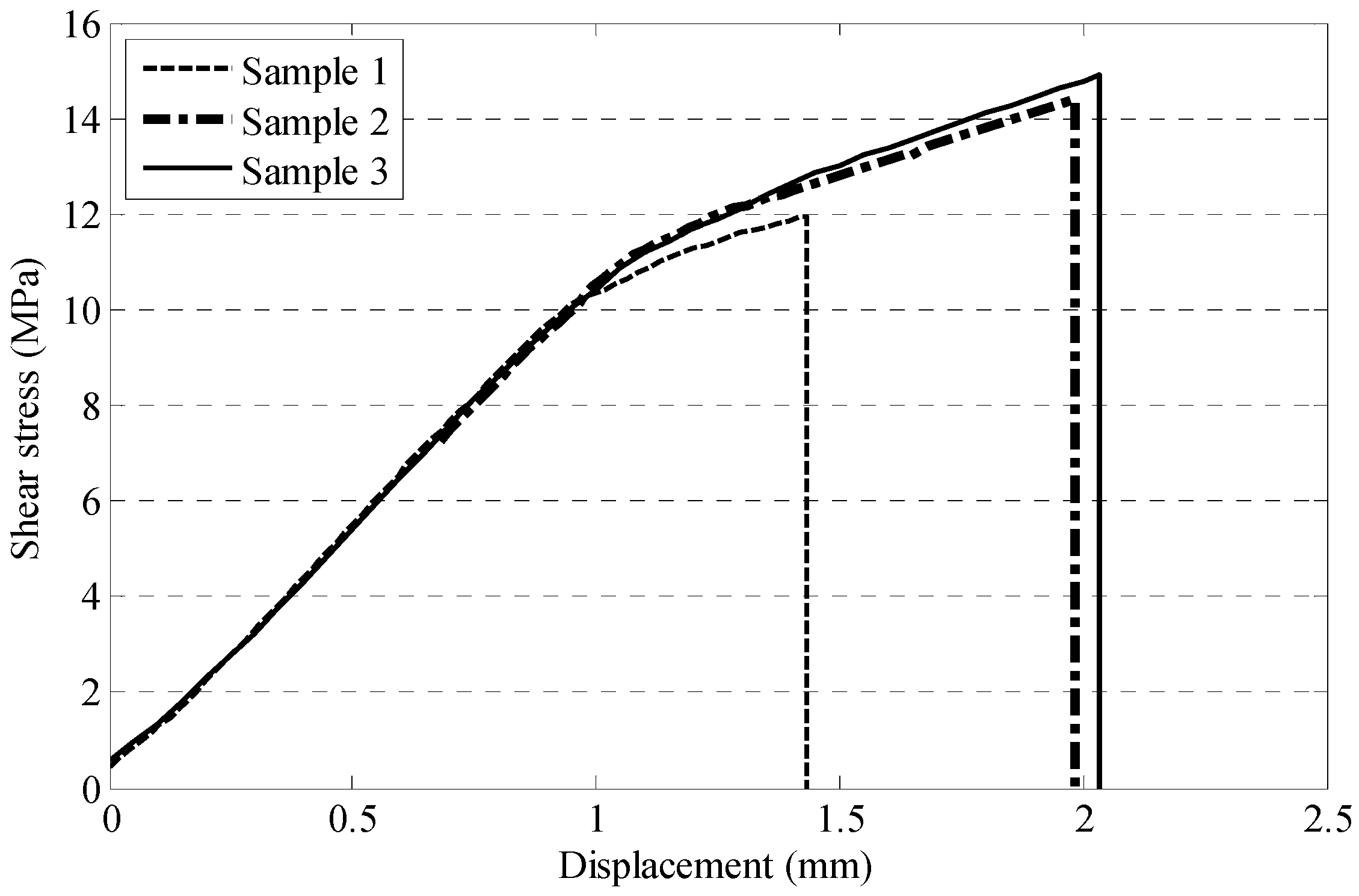
As shown in Figure 9, The specimen was prepared to have an overlap length of 55 mm at one end and 20 mm at the other end. Figure 10 shows the measured tensile stress curve for the steel plates with the CFRP obtained from the lap shear test. It was found that the ultimate shear strength was in the range of 12−14 MPa based on the assumption of uniform shear stress at the interface, which is consistent with the data reported in the literature [39].
5.2. Shear Stress between CFRP and Pipe
For the CFRP composite repair system, the maximum allowable shear stress at the interface between the CFRP and pipe wall should be lower than the shear bond strength, which is 12−14 Mpa, based on the previous experiment. In this section, the shear stress between the CFRP and pipe under the MAOP is analyzed by using the FE model presented in this study. The material properties were taken from Table 1. The maximum shear stress at the interface between the CFRP and the pipe wall is shown in Figure 11.
As shown in Figure 11, compared with CFRP wrap, CFRP patch tended to cause higher shear stress at the interface, for both 3.1 and 6.2 mm repair thicknesses. With the increase in the CFRP hoop length, the shear stress at the interface gradually decreased. The shear stress between the CFRP patches and the pipe wall was generally 3~4 times higher than that between the CFRP wraps and the pipe wall. Moreover, when the CFRP warps were used, the shear stress between the CFRP and the pipe wall was much smaller than the shear bond strength measured in the previous section. However, when the 3.1 mm CFRP patches were used, the shear stress between the CFRP and the pipe ranged from 12.3 to 13.9 MPa, which was close to the shear bond strength. This indicates that the CFRP patches with a thickness of 3.1 mm might fail under the MAOP, while for the 6.2 mm CFRP patches, the maximum shear stress between the CFRP and the pipe wall was always smaller than the shear bond strength. In general, when the CFRP thickness was higher, the interface shear stress was lower. This indicates that when the MAOP cannot be reduced, the repair system should be enhanced either by increasing the shear bonding strength between CFRP and steel or by increasing the thickness of the CFRP.
5.3. Effect of Interface Bonding on Pipe Stress
In the ideal condition, if the CFRP is fully bonded with the infill and the pipe wall, there should be no slip between these layers. However, if the bonds between these layers are not perfect, the performance of the pipe repair system could be influenced. In this section, FE models with different interface properties, namely, fully bonded and frictional conditions, are developed. In the frictional interface, the friction coefficient was set to be 1. The thickness of the CFRP was 6.2 mm. A CFRP patch with 220-mm length in the hoop direction and a CFRP wrap were simulated. Figure 12a,b show the maximum von Mises in the pipe wall and the maximum hoop stress in the CFRP under the MAOP, respectively. As shown in Figure 12a,b, compared with the fully bonded condition, the frictional interface caused a decrease in hoop stress in the CFRP but an increase in von Mises stress in the steel. This is mainly because in the frictional interface, finite slips between different layers were allowed in the tangential direction. Due to the slips, the deformation of the CFRP with a frictional interface would be smaller than that fully bonded with the pipe. As a result, compared with the fully bonded case, the frictional interface caused a decrease in stress in the CFRP but an increase in von Mises stress in the steel. This indicates the existence of an interface that might reduce the stress transfer from the steel to the CFRP. Therefore, effective adhesive should be applied between the CFRP and the infill/pipe wall to ensure enough bond between these layers.
6. Conclusions
This paper conducted finite element analysis to evaluate mechanical behavior of steel pipeline with CFRP repair systems. Two different repair strategies, namely, wrap repair and patch repair, were considered. The presented FE model was validated with experimental results of burst pressure. The following conclusions were concluded from the analysis:
- Both the von Mises stress in the pipe wall and the hoop stress in the CFRP could be reduced by using a thicker CFRP patch or CFRP wrap. With the increase in the patch size in the hoop direction, the maximum von Mises stress in the pipe wall generally decreased, while the maximum hoop stress in the CFRP increased. In theory, it is feasible to use CFRP patch instead of CFRP wrap in proper conditions.
- Both the von Mises stress in the pipe and hoop stress in the CFRP decreased with the increase in the elastic modulus of the filling material for all patch sizes. The reinforcement of the CFRP repair system could be enhanced by using infill with a higher elastic modulus.
- With the increase in adhesive thickness, the pipe wall carries the higher stress, while the CFRP carries the smaller stress. Therefore, excessive adhesive should be avoided, especially for pipes with large defects. Adhesive with a higher modulus should be used if the excessive adhesive cannot be avoided.
- The CFRP patch tended to cause higher interface shear stress than the CFRP wrap. The interface shear stress could be reduced by using thicker CFRP patches. Compared with the fully bonded condition, the frictional interface causes a decrease in hoop stress in the CFRP but an increase in von Mises stress in the steel. Effective adhesive should be applied between the CFRP and the infill/pipe wall to ensure enough bond between these layers.
The study findings indicate the feasibility of composite repair for a damaged steel pipeline. The results of this study provide reference for other types of pipe structures, such as a pipe-in-pipe system or composite pipeline [40]. Further research should be conducted to validate the analysis findings using full-scale tests and to optimize composite repair. The effectiveness of composite repair on pipeline performance under fatigue cyclic loads should also be studied in future work.
Author Contributions
Conceptualization, H.W. and P.N.B.; methodology, H.W. and J.C.; formal analysis, J.C.; investigation, J.C. and M.S.; writing—original draft preparation, J.C.; writing—review and editing, H.W.; supervision, H.W. All authors have read and agreed to the published version of the manuscript.
Funding
This research was funded by USDOT PHMSA through Competitive Academic Agreement Program (CAAP).
Institutional Review Board Statement
Not applicable.
Informed Consent Statement
Not applicable.
Conflicts of Interest
The authors declare no conflict of interest.
References
- Cosham, A.; Hopkins, P. The effect of dents in pipelines—guidance in the pipeline defect assessment manual. Int. J. Press. Vessel. Pip. 2004, 81, 127–139. [Google Scholar] [CrossRef]
- Ghaednia, H.; Das, S.; Wang, R.; Kania, R. Dependence of Burst Strength on Crack Length of a Pipe with a Dent-Crack Defect. J. Pipeline Syst. Eng. Pr. 2017, 8, 04016019. [Google Scholar] [CrossRef]
- Melchers, R.E. Probabilistic Model for Marine Corrosion of Steel for Structural Reliability Assessment. J. Struct. Eng. 2003, 129, 1484–1493. [Google Scholar] [CrossRef]
- De Meo, D.; Oterkus, E. Finite element implementation of a peridynamic pitting corrosion damage model. Ocean Eng. 2017, 135, 76–83. [Google Scholar] [CrossRef] [Green Version]
- Kim, D.K.; Wong, E.W.C.; Cho, N.-K. An advanced technique to predict time-dependent corrosion damage of onshore, offshore, nearshore and ship structures: Part I = generalisation. Int. J. Nav. Arch. Ocean Eng. 2020, 12, 657–666. [Google Scholar] [CrossRef]
- Mohd, M.H.; Kim, K.; Kim, D.W.; Paik, J.K. A time-variant corrosion wastage model for subsea gas pipelines. Ships Offshore Struct. 2014, 10, 1. [Google Scholar] [CrossRef]
- Mohd, M.H.B.; Kim, D.W.; Lee, B.J.; Kim, D.K.; Seo, J.K. On the burst strength capacity of an aging subsea gas pipeline. J. Off-shore Mech. Arct. Eng. 2014, 136, 041402. [Google Scholar] [CrossRef]
- Mohd, M.H.; Lee, B.J.; Cui, Y.; Paik, J.K. Residual strength of corroded subsea pipelines subject to combined internal pressure and bending moment. Ships Offshore Struct. 2015, 10, 1–11. [Google Scholar] [CrossRef]
- Fekete, G.; Varga, L. The effect of the width to length ratios of corrosion defects on the burst pressures of transmission pipe-lines. Eng. Fail. Anal. 2012, 21, 21–30. [Google Scholar] [CrossRef]
- Boswell, C.I.O.B.; Davies, I.J. Pipeline failures in corrosive environments—A conceptual analysis of trends and effects. Eng. Fail. Anal. 2015, 53, 36–58. [Google Scholar]
- Cheng, A.; Chen, N.-Z. An extended engineering critical assessment for corrosion fatigue of subsea pipeline steels. Eng. Fail. Anal. 2018, 84, 262–275. [Google Scholar] [CrossRef] [Green Version]
- Cao, Y.G.; Sun, X.Y.; Zhang, S.H.; Xue, S.F. Field experiments and FEM analysis of third-party damaged oil transmission pipe-line. Eng. Fail. Anal. 2010, 17, 344–352. [Google Scholar] [CrossRef]
- Chapetti, M.; Otegui, J.; Manfredi, C.; Martins, C. Full scale experimental analysis of stress states in sleeve repairs of gas pipelines. Int. J. Press. Vessel. Pip. 2001, 78, 379–387. [Google Scholar] [CrossRef]
- Otegui, J.; Rivas, A.; Manfredi, C.; Martins, C. Weld failures in sleeve reinforcements of pipelines. Eng. Fail. Anal. 2001, 8, 57–73. [Google Scholar] [CrossRef]
- Alian, A.R.; Shazly, M.; Megahed, M.M. 3D finite element modeling of in-service sleeve repair welding of gas pipelines. Int. J. Press. Vessel. Pip. 2016, 146, 216–229. [Google Scholar] [CrossRef]
- Asl, H.M.; Vatani, A. Numerical analysis of the burn-through at in-service welding of 316 stainless steel pipeline. Int. J. Press. Vessel. Pip. 2013, 105–106, 49–59. [Google Scholar] [CrossRef]
- Farzadi, A. Gas Pipeline Failure Caused by In-Service Welding. J. Press. Vessel. Technol. 2015, 138, 011405. [Google Scholar] [CrossRef]
- Duell, J.; Wilson, J.; Kessler, M. Analysis of a carbon composite overwrap pipeline repair system. Int. J. Press. Vessel. Pip. 2008, 85, 782–788. [Google Scholar] [CrossRef]
- Lyapin, A.A.; Chebakov, M.I.; Dumitrescu, A.; Zecheru, G. Finite-Element Modeling of a Damaged Pipeline Repaired Using the Wrap of a Composite Material. Mech. Compos. Mater. 2015, 51, 333–340. [Google Scholar] [CrossRef]
- Junior, M.W.; Reis, J.; Mattos, H.D.C. Polymer-based composite repair system for severely corroded circumferential welds in steel pipes. Eng. Fail. Anal. 2017, 81, 135–144. [Google Scholar] [CrossRef]
- Mattos, H.S.D.; Reis, J.M.L.; Paim, L.M.; da Silva, M.L.; Junior, R.L.; Perrut, V.A. Failure analysis of corroded pipe-lines reinforced with composite repair systems. Eng. Fail. Anal. 2016, 59, 223–236. [Google Scholar] [CrossRef]
- Akram, A.; Mustaffa, Z.; Albarody, T.M.B. Burst capacity of pipe under corrosion defects and repaired with thermosetting liner. Steel Compos. Struct. 2020, 35, 171–186. [Google Scholar]
- Setvati, M.R.; Mustaffa, Z. Rehabilitation of corroded circular hollow sectional steel beam by CFRP patch. Steel Compos. Struct. 2019, 32, 127–139. [Google Scholar]
- Seica, M.V.; Packer, J.A. FRP materials for the rehabilitation of tubular steel structures, for underwater applications. Compos. Struct. 2007, 80, 440–450. [Google Scholar] [CrossRef]
- De Barros, S.; Banea, M.D.; Budhe, S.; De Siqueira, C.E.R.; Lobão, B.S.P.; Souza, L. Experimental analysis of metal-composite repair of floating offshore units (FPSO). J. Adhes. 2017, 93, 147–158. [Google Scholar] [CrossRef]
- Rohem, N.; Pacheco, L.; Budhe, S.; Banea, M.; Sampaio, E.; De Barros, S. Development and qualification of a new polymeric matrix laminated composite for pipe repair. Compos. Struct. 2016, 152, 737–745. [Google Scholar] [CrossRef]
- Alexander, C.; Ochoa, O.O. Extending onshore pipeline repair to offshore steel risers with carbon—Fiber reinforced compo-sites. Compos. Struct. 2010, 92, 499–507. [Google Scholar] [CrossRef]
- Shouman, A.; Taheri, F. Compressive strain limits of composite repaired pipelines under combined loading states. Compos. Struct. 2011, 93, 1538–1548. [Google Scholar] [CrossRef]
- Keller, M.W.; Jellison, B.D.; Ellison, T. Moisture effects on the thermal and creep performance of carbon fiber/epoxy compo-sites for structural pipeline repair. Compos Part B 2013, 45, 1173–1180. [Google Scholar] [CrossRef]
- Mazurkiewicz, L.; Tomaszewski, M.; Malachowski, J.; Sybilski, K.; Chebakov, M.; Witek, M.; Yukhymets, P.; Dmitrienko, R. Ex-perimental and numerical study of steel pipe with part-wall defect reinforced with fibre glass sleeve. Int. J. Press. Vessels Pip. 2017, 149, 108–119. [Google Scholar] [CrossRef]
- Saeed, N.; Ronagh, H.; Virk, A. Composite repair of pipelines, considering the effect of live pressure-analytical and numeri-cal models with respect to ISO/TS 24817 and ASME PCC-2. Compos Part B 2014, 58, 605–610. [Google Scholar] [CrossRef]
- The American Society of Mechanical Engineers. Repair of Pressure Equipment and Piping; ASME PCC-2-2006; ASME: New York, NY, USA, 2006. [Google Scholar]
- Cunha, S.B.; Netto, T.A. Analytical solution for stress, strain and plastic instability of pressurized pipes with volumetric flaws. Int. J. Press. Vessel. Pip. 2012, 89, 187–202. [Google Scholar] [CrossRef]
- Theisen, S.A.; Keller, M.W. Comparison of Patch and Fully Encircled Bonded Composite Repair. In Mechanics of Composite and Multi-Functional Materials; Society for Experimental Mechanics Series; Springer International Publishing: Berlin/Heidelberg, Germany, 2017; Volume 7, pp. 101–106. [Google Scholar]
- Ayaz, Y.; Çitil, Ş.; Şahan, M.F. Repair of small damages in steel pipes with composite patches. Mater. Werkst. 2016, 47, 503–511. [Google Scholar] [CrossRef]
- ASTM. Standard Specification for Seamless Carbon Steel Pipe for high-Temperature Service. ASTM C1754-12; ASTM: West Conshohocken, PA, USA, 2018. [Google Scholar] [CrossRef]
- Schnerch, D.; Stanford, K.; Sumner, E.A.; Rizkalla, S. Strengthening Steel Structures and Bridges with High-Modulus Carbon Fiber-Reinforced Polymers Resin Selection and Scaled Monopole Behavior. Transp. Res. Rec. J. Transp. Res. Board 2004, 1892, 237–245. [Google Scholar] [CrossRef] [Green Version]
- ASTM. Standard Test Method for Apparent Shear Strength of Single-Lap-Joint Adhesively Bonded Metal Specimens by Tension Loading (Metal-to-Metal). ASTM D1002-10; ASTM: West Con-shohocken, PA, USA, 2019. [Google Scholar] [CrossRef]
- Balaguru, P.N.; Lee, K.W. Effectiveness of High Strength Composites as Structural and Protective Coating for Structural El-Ements; Final Report NETCR 28; TRB: New York, NY, USA, 2001. [Google Scholar]
- Jiwa, M.; Kim, D.; Mustaffa, Z.; Choi, H. A systematic approach to pipe-in-pipe installation analysis. Ocean Eng. 2017, 142, 478–490. [Google Scholar] [CrossRef]
Figure 1.
Model dimension: (a) whole model, (b) defect, (c) wrap repair, and (d) patch repair.

Figure 2.
Maximum stress under different internal pressures for (a) 152.4 mm defect and (b) full-circle defect.
Figure 2.
Maximum stress under different internal pressures for (a) 152.4 mm defect and (b) full-circle defect.

Figure 3.
Validation of FE model for burst pressure.

Figure 4.
Maximum von Mises stress in the pipe wall for different CFRP sizes.

Figure 5.
Maximum hoop stress in the pipe wall for different CFRP sizes.

Figure 6.
Effect of infill modulus on (a) von Mises stress in pipe and (b) hoop stress in CFRP.

Figure 7.
Effect of adhesive on von Mises stress in pipe with infill material of (a) 1.74 GPa epoxy and (b) 10 GPa inorganic composite.
Figure 7.
Effect of adhesive on von Mises stress in pipe with infill material of (a) 1.74 GPa epoxy and (b) 10 GPa inorganic composite.

Figure 8.
Effect of adhesive on hoop stress in pipe with infill material of (a) 1.74 GPa epoxy and (b) 10 GPa inorganic composite.
Figure 8.
Effect of adhesive on hoop stress in pipe with infill material of (a) 1.74 GPa epoxy and (b) 10 GPa inorganic composite.

Figure 9.
Laboratory setup for the lap shear test.

Figure 10.
Measured stress from the lap shear test.

Figure 11.
Shear stress between the CFRP and pipe wall.

Figure 12.
Effect of interface property on (a) von Mises stress in pipe and (b) hoop stress in CFRP.
Figure 12.
Effect of interface property on (a) von Mises stress in pipe and (b) hoop stress in CFRP.


Table 1.
Material properties in finite element (FE) model (After Duell et al. 2008 [18]).
Table 1.
Material properties in finite element (FE) model (After Duell et al. 2008 [18]).
| Material | Properties | |||
|---|---|---|---|---|
| Linear (Below Yield) | Nonlinear (Above Yield) | |||
| Steel | Young′s Modulus | 207 GPa | Yield Stress (MPa) | Plastic Strain |
| 301 | 0.0000 | |||
| 317 | 0.0029 | |||
| 374 | 0.0138 | |||
| 412 | 0.0207 | |||
| Poisson′s Ratio | 0.3 | 482 | 0.0386 | |
| 534 | 0.0575 | |||
| 596 | 0.0862 | |||
| 648 | 0.1222 | |||
| Epoxy | Young′s Modulus | 1.74 GPa | Yield Stress | 33 MPa |
| Poisson′s Ratio | 0.45 | Tangent Modulus | 0.87 GPa | |
| CFRP | Young′s Modulus | E1 5.5 GPa (radial) | Poisson′s Ratio (assumed) | ν12 0.1 |
| E2 49 GPa (hoop) | ν13 0.4 | |||
| E3 23.4 GPa (axial) | ν23 0.4 | |||
| Shear Modulus | G12 29.6 GPa | |||
| G13 0.69 GPa | ||||
| Ultimate Hoop Strength | G23 0.69 GPa 576 MPa | |||
Publisher’s Note: MDPI stays neutral with regard to jurisdictional claims in published maps and institutional affiliations. |
© 2021 by the authors. Licensee MDPI, Basel, Switzerland. This article is an open access article distributed under the terms and conditions of the Creative Commons Attribution (CC BY) license (http://creativecommons.org/licenses/by/4.0/).
Share and Cite
MDPI and ACS Style
Chen, J.; Wang, H.; Salemi, M.; Balaguru, P.N. Finite Element Analysis of Composite Repair for Damaged Steel Pipeline. Coatings 2021, 11, 301. https://0-doi-org.brum.beds.ac.uk/10.3390/coatings11030301
AMA Style
Chen J, Wang H, Salemi M, Balaguru PN. Finite Element Analysis of Composite Repair for Damaged Steel Pipeline. Coatings. 2021; 11(3):301. https://0-doi-org.brum.beds.ac.uk/10.3390/coatings11030301
Chicago/Turabian StyleChen, Jiaqi, Hao Wang, Milad Salemi, and Perumalsamy N. Balaguru. 2021. "Finite Element Analysis of Composite Repair for Damaged Steel Pipeline" Coatings 11, no. 3: 301. https://0-doi-org.brum.beds.ac.uk/10.3390/coatings11030301
Note that from the first issue of 2016, this journal uses article numbers instead of page numbers. See further details here.