Review

Surface Modification and Functional Structure Space Design to Improve the Cycle Stability of Silicon Based Materials as Anode of Lithium Ion Batteries

1
School of Chemical Engineering, University of Science and Technology Liaoning, Anshan 114051, China
2
Key Laboratory of Energy Materials and Electrochemistry Research Liaoning Province, University of Science and Technology Liaoning, Anshan 114051, China
3
State Key Laboratory of Metal Material for Marine Equipment and Application, Anshan 114009, China
4
College of Pharmacy, Nankai University, Tianjin 300071, China
*
Authors to whom correspondence should be addressed.
Submission received: 30 June 2021 / Revised: 19 July 2021 / Accepted: 23 July 2021 / Published: 30 August 2021
(This article belongs to the Special Issue Surface Modification and Functionalization for Advanced Materials)

Abstract

:
Silicon anode is considered as one of the candidates for graphite replacement due to its highest known theoretical capacity and abundant reserve on earth. However, poor cycling stability resulted from the “volume effect” in the continuous charge-discharge processes become the biggest barrier limiting silicon anodes development. To avoid the resultant damage to the silicon structure, some achievements have been made through constructing the structured space and pore design, and the cycling stability of the silicon anode has been improved. Here, progresses on designing nanostructured materials, constructing buffered spaces, and modifying surfaces/interfaces are mainly discussed and commented from spatial structure and pore generation for volumetric stress alleviation, ions transport, and electrons transfer improvement to screen out the most effective optimization strategies for development of silicon based anode materials with good property.

1. Introduction

To meet the global energy and environmental demands, tremendous efforts have been devoted to exploring green energy systems [1], however, it is seriously limited by intermittent production of these energies, such as wind and solar powers. Therefore, the efficient utilization of green energy requires the carrier for convenient energy storage and power transfer [2,3,4]. Rechargeable lithium-ion batteries (LIBs) are a very common energy storage device due to their high energy density, high voltage, and environmental friendliness [5], which has tried to apply in electronic devices, electric vehicles, and energy storage stations.
The reversible storage capacity of commercial LIBs depends on the properties of the electrode materials. Presently, the most used anode materials of LIBs are carbonaceous materials including graphite, carbon microbeads and porous carbons, etc. However, the theoretical capacity of the widely used graphite anode is 372 mA·h·g−1 owing to the mechanism by the insertion and disinsertion of lithium ions [6]. To significantly increase the energy density of anodes, the materials for lithium ions storage by alloying and dealloying are expected [7,8]. Among alloying anode materials, silicon has the highest theoretical capacity up to 4200 mA·h·g−1, which corresponds to the alloying reaction as shown in Equation (1) [9,10]. However, there is also a relatively lower level of lithiation reaction of Si corresponded to Equation (2) at room temperature, and its theoretical capacity of lithium is 3579 mA·h·g−1 [11,12].
22 Li + 5 Si → Li22Si5
15 Li + 4 Si → Li15Si4
In addition to the high capacity of lithium storage, Si has the advantage of becoming an anode material for commercial lithium-ion batteries. It is the second abundant element in earth’s crust, low cost, and harmless to the environment. Silicon anode has a low charge -discharge voltage plateau (average charge-discharge voltage potential of Si is ca. 0.4 V vs. Li/Li+), which can avoid the phenomenon of surface lithium plating and Lithium dendrites and thus improve the safety of LIBs [13].
Despite these advantages, the commercialization of silicon based anodes for LIBs is still heavily limited by their poor cycling stability due to the large volume changes of Si during lithiation and delithiation. As a result, the mechanical stress resulted from the volume change of Si anode causes the cracks and pulverization of anode materials, and thus the structures of active materials are destroyed (Figure 1), resulting in a rapid capacity reduction of LIBs [14,15]. The volume effects of silicon anode also cause the solid electrolyte interface (SEI) film to be unstable since the volume stress makes the SEI film around silicon materials destroyed, however, SEI film regenerates once LIBs is charging. These repeated processes can not only consume the limited electrolyte inside the battery but also thicken SEI film, which hinders the diffusion of Li ions through the silicon material and thus results in an increase in electrical resistance of the electrode (Figure 2) [16]. The other main drawback of silicon anode is its low electronic and ionic conductivity, which goes against the energy and power density of silicon anode.
To pave the way for efficient utilization of silicon anode, many efforts have been paid to solve these bottleneck problems. In this review, the progress to improve silicon anodes through the design and construction of structural space in silicon-based materials over the years are systematically summarized. More attention is paid to constructing the space structure or designing the porous structure of silicon anode to buffer the volumetric effects. It has been reviewed from the aspects of silicon nanostructure to minimize volumetric stress, the composite structure of carbon and silicon to build buffering space, and porous silicon to accommodate volumetric inflation.

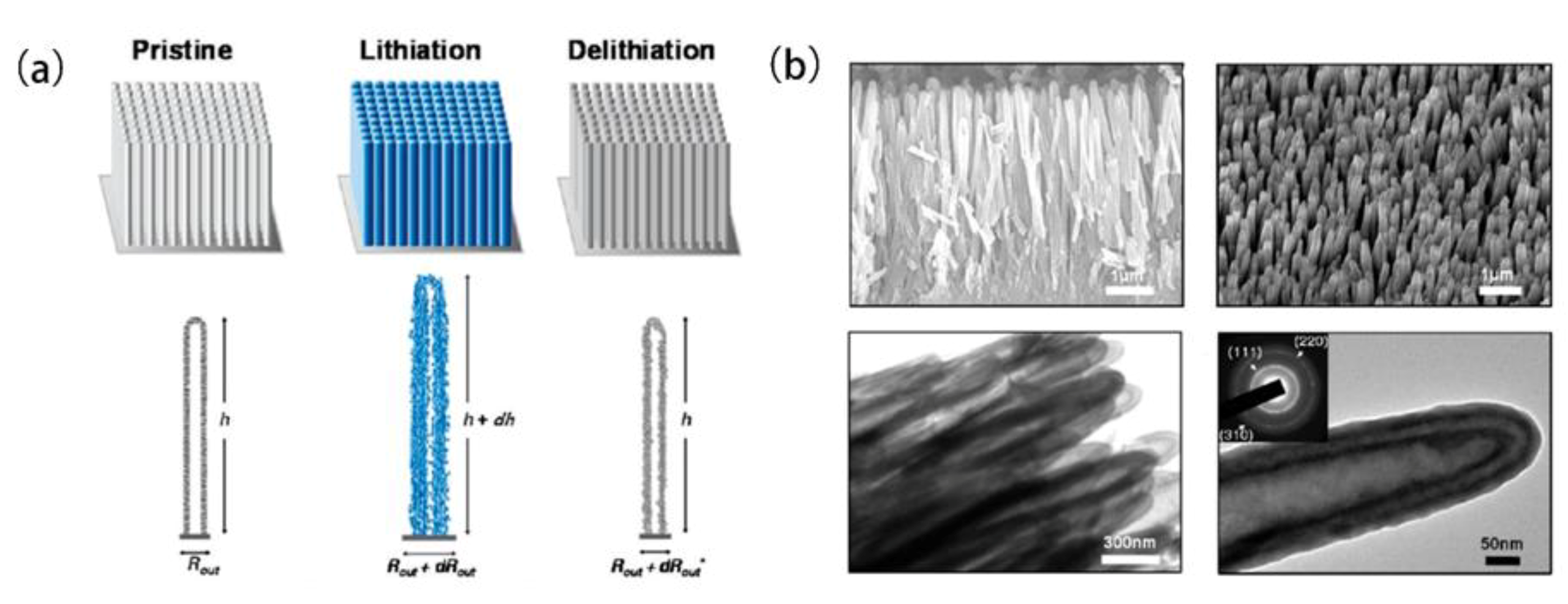
2. Nanostructured Silicon

Nano sizing silicon can prevent the electrode from cracking caused by volume ex-pansion of silicon lithiation and shorten the transport distance of ions and electrons. In 2011, Liu and Huang [17] used in-situ transmission electron microscopy to determine the critical diameter of silicon particles that prevents fragmentation. The results showed that the critical size is about 150 nm. However, using the commercial nano-silicon powders as anode material of LIBs, Chen et al. [18] did not get a good cycling performance of anode. Actually, nano-silicon anode still suffers from the failures during cycling. The vigorous expanding of nano-silicon resulted from lithiation causes the silicon nanoparticles in the electrode to press against each other, however, the delithiation process results in the shrinking of silicon particles in the electrode (Figure 3) [19]. These repeated processes during charge-discharge make the silicon nanoparticles detached from the current collector and, thus, no longer contribute to the capacity of lithium ions storage.
To buffer the stress generated by the volume change during lithiation/delithiation of silicon, it is considered that changing the morphology of nano-silicon is an effective way. One-dimensional nanomaterials like silicon nanowires and silicon nanotubes can buffer volumetric stress by their longitudinal ductility, which could avoid the separation of active materials from the current collector [20]. Chan et al. [21] synthesized silicon nanowire (SiNW) on a stainless-steel substrate by the vapor-liquid-solid template-free growth method. SiNW anode showed a large capacity of 3000 mA·h·g−1 or more at a current density of 210 mA·g−1, with a little degradation after 10 cycles. Cui et al. [22] used a simple one-step synthesis method to coat an amorphous Si-shell on the basis of crystalline SiNW as a stable mechanical support (Figure 4a). The charge storage capacity of these core-shell nanowires is about 1000 mA·h·g−1 at 860 mA·g−1, and the capacity retention rate is about 90% after 100 cycles. Ruffo et al. [23] successfully fabricated large-area SiNW arrays by using stainless steel 304 covered with Au as the catalyst, which exhibited a specific capacity of about 2800 mA·h·g−1 with 85% retention after 50 cycles and more than 99% Coulombic efficiency. SiNW arrays as prepared are neatly arranged on the current collector, the loose nanowire structure leaves a volume both in the axial and the radial direction less prone to the breakage during charge-discharge. Moreover, Wang et al. [24] coated the graphene (GR) layer on SiNWs (SiNW@G) and then coated the SiNW@G with the reduced graphene oxide (RGO) to obtain the SiNW@G@RGO material (Figure 4b). Both the GR and RGO have good conductivity and flexibility, which can improve the electronic conductivity of the anode. The advantage of this structure is that the overlapping graphene sheets can act as an adaptable but sealed sheath that prevents the encapsulated silicon from being directly exposed to the electrolyte and enables the structural and interfacial stability of SiNW. At the same time, the flexible conductive RGO can accommodate the volume change of SiNW@G nanocable. Therefore, the SiNW@G@RGO electrode exhibited a high reversible specific capacity of 1600 mA·h·g−1 at 2.1 A·g−1 and a capacity retention of 80% after 100 cycles. Song et al. [25] constructed a bottom-up hierarchical buffering structure through copper-silicon nanowire hybrids, which can provide electron transport pathways, stable mechanical supports and leave enough room for the expansion of silicon during cycles. After 800 cycles, the reversible capacity of 830 mA·h·g−1 and the capacity retention was 85% can be obtained.
The advantage of silicon nanotube (SiNT) over SiNW is that the hollow inside tube provides space for volume expansion of silicon and reduces overall volume change [26] The tubular structure of SiNT is usually constructed by etching a template, Park, et al. [27] reported on Si nanotubes prepared from aluminum oxide templates and silicon precursors that were reductively decomposed during etching, which has a reversible capacity of about 3200 mA·h·g-1 and retention of 89% after 200 cycles at a rate of 3 A·g−1. Similar to the SiNW arrays, the SiNT arrays (Figure 5a) were also developed by Song and his colleagues using the zinc oxide nanorod arrays as the sacrificial template [28]. The SiNT arrays were coated with highly conductive Ge (Figure 5b), and the type of SiNT/Ge double-layer nanotube array electrode has better performance than the bare SiNT array electrode. After 50 cycles, the reversible capacity is about 1300 mA·h·g−1 with a retention rate of 85% [29]. Although the structure is held to a large extent by using SiNT, the interface of SiNT is not static due to volume expansion, and repeated rupture of the SEI film is an-other critical factor that limits the cycling stability of silicon. Wu et al. [30] designed and synthesized a novel double-walled Si–SiOx nanotube(DWSiNT) anode. SiNTs vapor-deposited on carbon nanofibers were coated with an ion-permeable silicon oxide shell to prevent the volume from expanding outward. The capacity of 1350 mA·h·g−1 can be obtained at 0.2 C after 800 cycles. Especially, at a large rate of 12 C, the capacity of 560 mA·h g−1 can be still kept even after 6000 cycles. It was deduced that the silicon oxide shell forced the volume expansion inward the silicon, and can react with the elec-trolyte to form a stable SEI film.

3. Composite Structure of Silicon/Carbon

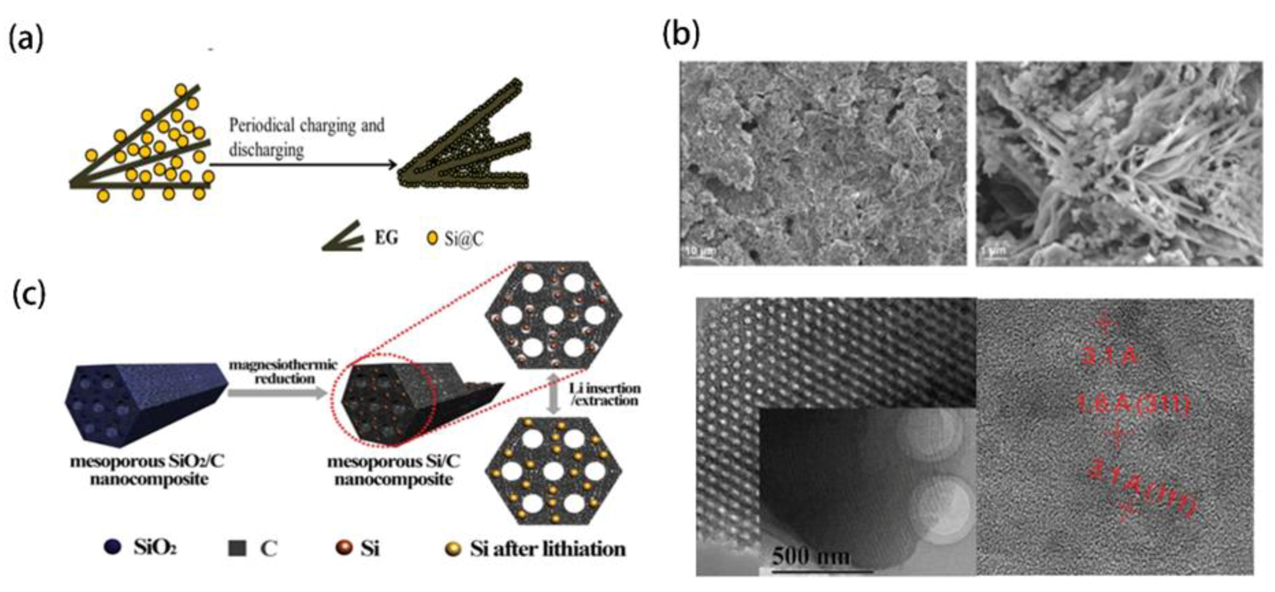
3.1. Embedded Structure of Silicon in Carbon Skeleton

Carbon materials have some advantages of tunable structure for compositing with silicon, good conductivity and porosity for ions and electrons transfer, good mechanical and chemical stability for LIBs. Carbon skeleton has been used to buffer volume expansion of silicon lithiation, meanwhile tenace electronic and ionic conductivity of electrode, and improve performance of silicon based anode. Amorphous carbon can also act as an excellent dispersion matrix for silicon nanoparticles to construct space for alleviating volumetric expansion of silicon lithiation. However, the weak mechanical strength of amorphous carbon makes the composite structure easy to be damaged during cycles. Kwon et al. [31] prepared the silicon quantum dots with a size of less than 5 nm through the reduction of SiCl4 by sodium naphthalene. Silicon quantum dots as prepared are completely covered by amorphous carbon layers. Thereafter, the aggregation of silicon dots during charge-discharge is inhibited and cycling performance of silicon anode is improved. Mesocarbon microbeads (MCMB) have been extensively studied as carbon-based anode materials. Wang et al. [32] used ball milling to evenly distribute nano-silicon particles in the structural gaps of MCMB, the silicon-carbon composite structure can disperse the stress generated by lithiation and delithiation of silicon. The Si-MCMB anode demonstrated a reversible capacity of 1066 mA·h·g−1, which decayed to about 700 mA·h·g−1 after 25 cycles. Magasinski et al. [33] used the annealed carbon blacks as a structural scaffold to deposit silicon nanoparticles by CVD. The carbon blacks between the silicon particles construct the channels that allow lithium ions to rapidly transfer and the voids that adjust the volume change resulted from lithiation and delithiation of silicon. The composite material of silicon exhibited a reversible capacity of 1590 mA·h·g−1 at 1 C after 100 cycles. Recently, Zhu et al. [34] developed the silicon nanodots encapsulated in a double-shell hollow carbon nanosphere (SiNDs@DSHC), which exhibited the reversible capacity of 1350 mA·h·g−1 at a 0.3 A·g−1 after 400 cycles.
Graphite was often introduced into silicon-graphite-amorphous carbon (Si-G-C) composite system due to its high conductivity and high lithium storage capacity. Graphite acts as a conductive agent and auxiliary lithium storage material, amorphous carbon bonds the individual components of the composite [35]. Jo et al. [36] evaluated the cyclic stability of different distribution positions of 20% Si by preparing two Si-G-C composite materials. Type A that Si particles were distributed on the surface of graphite. Type B that Si particles were embedded inside the graphite particle. Electrochemical characterization shows that the cycle stability of B-type material is poor. Jo et al. believe that the reason is the loss of electrical contact caused by the agglomeration of Si particles and the loss of capacity caused by the damaged graphite. Ma et al. [37] mixed and dissolved silicon nanoparticles, exfoliated graphite (EG), and polyvinyl chloride in tetrahydrofuran (Figure 6a,b). After the evaporation of the solvent, the obtained solid mixture was carbonized to produce the composite of Si-EG-C. Since the exfoliated graphite has a high porosity, excellent electronic conductivity, and good flexibility, it can alleviate the volumetric stress resulted by lithiation of silicon. Therefore, the anode of Si-EG-C exhibited a reversible capacity of 902.8 mA·h·g−1 at 200 mA·g−1 and a capacity retention rate of 98.4% after 40 cycles.
The carbon material with uniformly distributed pores facilitates the rapid transmission of lithium ions at the interface between the electrolyte and the silicon particles, and provides a buffer space for the volume expansion of silicon. By using the triblock copolymer of pluronic F127 and resorcinol-formaldehyde polymer as the template agent and carbon precursor, respectively, Park et al. [38] prepared Si nanoparticles embedded in an ordered mesoporous carbon (OMC) composite through one-step self-assembly and solvent evaporation route. As the anode materials of LIBs, the Si@OMC exhibited a high reversible capacity above 700 mA·h·g−1 at 2 A·g−1 for 50 cycles. However, it was believed that commercial silicon nanoparticles might interpenetrate the mesoporous channels of carbon and thus block and limit the diffusion of electrolyte, resulting in low capacity and coulombic efficiency due to the large particle size (>30 nm) of Si. Zhang et al. [39] improved the above preparation method of Si@OMC (Figure 6c), successfully prepared the nanocomposites of OMC and silicon with the specific surface area of 1290 m2·g−1. In the composite, the silicon nanoparticles (about 3 nm) were uniformly embedded in the mesoporous carbon skeleton. As the anode material of LIBs, the composite has a high reversible capacity of 1790 mA·h·g−1 and the coulombic efficiency of 99%, the capacity can still be maintained at 1480 mA·h·g−1 after 1000 cycles at 2 A·g−1. Zeng et al. [40] also reported a similar composite, Si/amorphous SiO2 nanoparticles were encapsulated into the OMC. The amorphous SiO2 nanoparticles uniformly dispersed in the OMC matrix can further reduce the volume change of the active material during the cycling, and can also promote the diffusion of Li ions. As anodes for LIBs, the composites exhibit a reversible capacity of 958 mA·h·g−1 at 200 mA·g−1 after 100 cycles. Owing the highly porous structure, metal organic framework (MOF) derived carbon was used as a dispersion matrix of silicon nanoparticles by Gao et al. [41] the composite electrode as prepared delivered a capacity of 3714 mA·h·g−1 at 200 mA·g−1 and a reversible capacity of 820 mA·h·g−1 at 5000 mA·g−1 even after 1000 cycle. MXene with a layered structure was also used as a dispersion matrix of nanosilicon [42]. Xia et al. [43] prepared the porous silicon nanospheres wrapped by MXene. Since the strong interface interaction between silicon and MXene, the silicon based anode exhibited good durability.

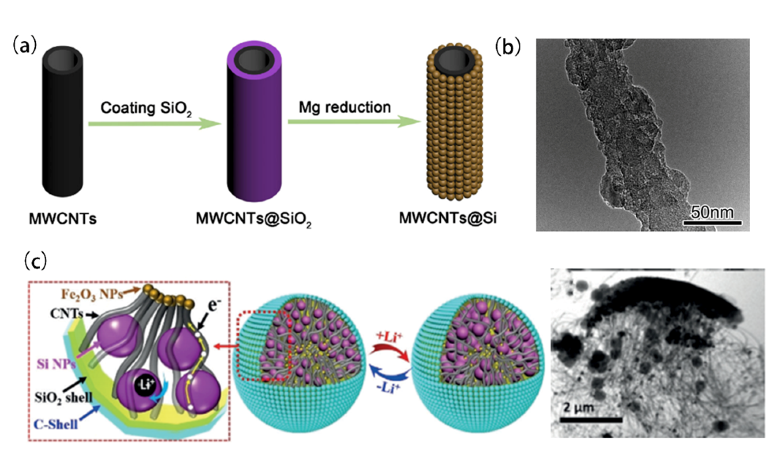
3.2. Coxial Structure of Carbon and Silicon

SiNW and SiNT with a one-dimensional structure had been demonstrated to reduce the possibility of structural cracking during the recycling process. However, the complicated preparation process and low yield directly hinder their large-scale application. Both carbon nanofibers (CNFs) and carbon nanotubes (CNTs) have a quasi-one-dimensional morphology. Their mechanical and electronic properties mainly benefit from the high ratio of length and radius. By utilizing the unusual characteristics of CNFs and CNTs, silicon-based anode with the coaxial structure of silicon and carbons can obtain a high capacity and improved durability. Gómez [44] et al., fixed silicon nanoparticles on the hydroquinone/formaldehyde polymer fiber (RF), to obtain Si particles through heat treatment to anchor on the surface of the carbon nanofiber. The CNF/Si composite material provides a specific capacity of 2500 mA·h·g−1 at 500 mA·g−1, and maintains a specific capacity greater than 2200 mA·h·g−1 after 50 cycles. CNTs are also used for recombination with silicon nanoparticles. Zhang et al. [45] mixed the CNTs, CNFs with carbon coated silicon (Si@C) spherical composites by a series of high-energy wet ball-milling, spray drying and subsequently chemical vapor deposition methods. The CNTs and CNFs were intertwined with Si@C to form the considerable space among the Si@C particles in the composites, which can withstand the volumetric expansion of silicon during lithium insertion, thereby improving the cycle stability of the anode. The high initial specific discharge capacity is approximately 2169 mA·h·g−1 and a reversible specific capacity approached 1195 mA·h·g−1 after 50 cycles at 300 mA·g−1. In order to obtain the higher degree of coverage of Si on CNTs, Chen et al. [18] oxidized the CNT with nitric acid and ncapsulated made the SiO2 coating (CNT@SiO2) by the sol-gel method, and then reduced CNT@SiO2 into CNT@Si (Figure 7a,b) by molten Mg. The surface of the CNT@Si sample is smooth and small silicon particles distributed uniformly were observed by TEM, the CNT@Si nanocomposites show less capacity fading, and a capacity of 800 mA·h·g−1 is achieved after 70 cycles at 500 mA·g−1. A similar structure was also successfully constructed by Liu et al. [46] In the process of synthesizing the SiO2 layer, CTAB was introduced to increase the adhesion of nano-silicon to CNT. In addition, a carbon coating was added to the surface of the silicon layer. The CNT@Si@C sandwich material showed an excellent cycle performance as the anode of LIBs due to that the sandwich-like hollow tube structure of CNT@Si@C not only alleviates the volume change during cycling, but also facilitates Li ions and electrons transport. Therefore, a stable reversible discharge capacity up to 1508 mA·h·g−1 after 1000 cycles was obtained. Zhang et al. [47] constructed a more macroscopic carbon shell to provide internal pores for the volume expansion of silicon, while the coaxial structure of conductive CNTs served as the bridged spaces between the silicon core and the carbon shell (Figure 7c). The half-cell tests showed that a high area capacity of 3.6 mA·h·cm−2 and 95% capacity retention after 450 cycles can be obtained. Jia et al. [48] designed and developed CNT@Si@C microspheres, which can absorb the volume change of Si and hence demonstrate apparent particle expansion of ~30% upon full lithiation, the composite electrodes deliver ~750 mA·h·g−1 specific capacity, <20% initial swelling at 100% state of charge, and ~92% capacity retention after 500 cycles. Wang et al. [49] designed a cellulose-based topological microscroll, and made the carbon-coated silicon nanoparticles anchored on the conductive carbon nanotubes and then confined in a cellulose carbon microscroll, which can supply enough internal voids to accommodate the volume expansion of silicon. The materials as the anode of LIBs supplied a capacity of 2700 mA·h·g−1.

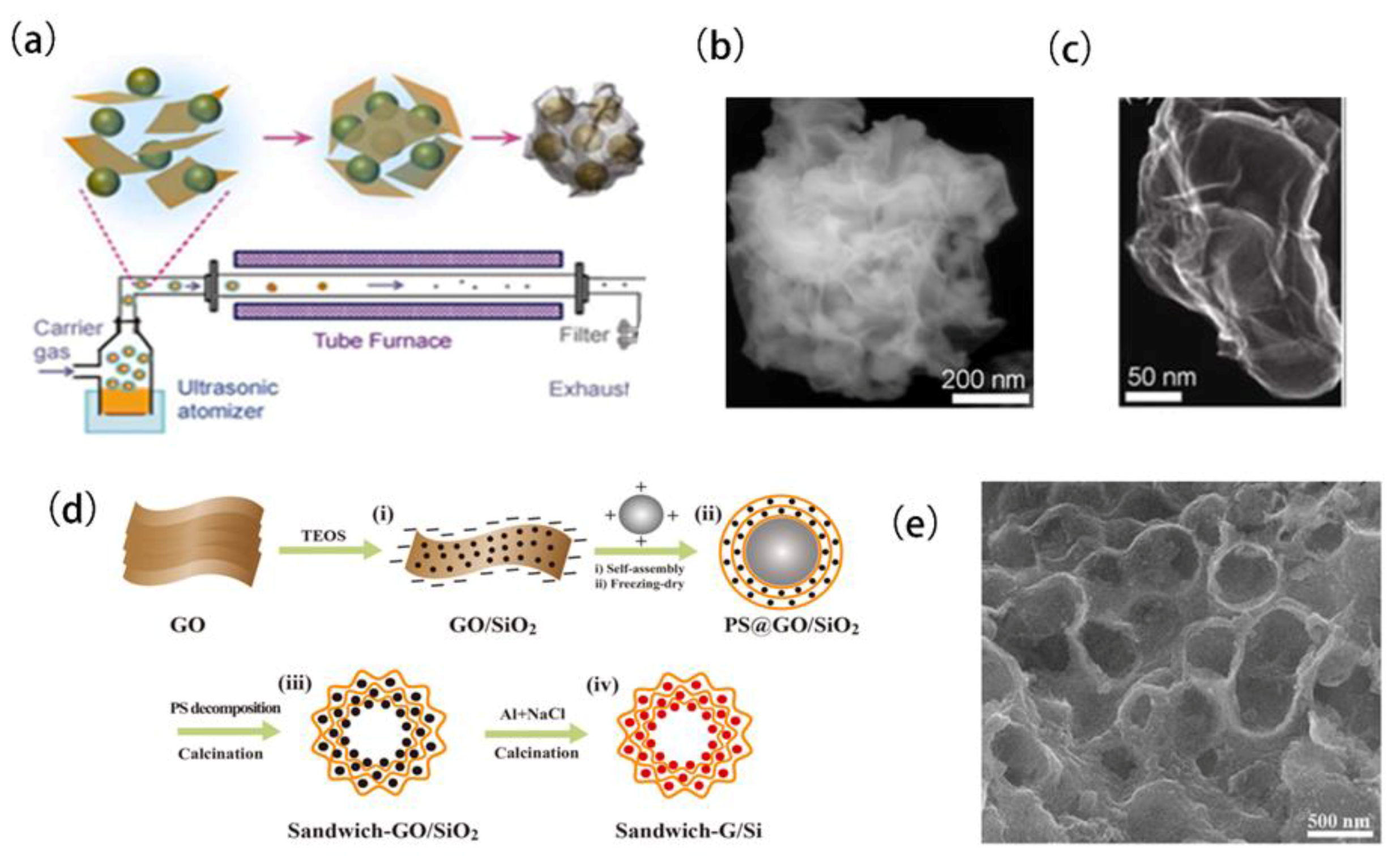
3.3. Package Structure with Graphene

Graphene (GR) has a unique 2D planar structure that can be combined with silicon to construct a silicon/graphene composite with a “package structure” in which. Silicon nanoparticles are distributed between the stacked graphene. Owing to the excellent property of graphene in electronics, mechanics, and structure, the stacked graphene can effectively buffer the volumetric stress resulted by silicon lithiation, inhibit the agglomeration of silicon particles and enhance the ionic and electronic conductivity of anode, therefore give the silicon-based materials promising perspectives as the anode of LIBs. Zhao et al. [50] used HNO3 solution treated graphene oxide (GO) flakes as a support for the “sandwich” structure. The surface of GO contains more oxygen-containing functional groups and has better hydrophilicity, and the advantage of this structure is that Li ions can easily pass through the entire structure of the composite by passing through in plane carbon vacancy defects. After 150 cycles, the composite maintained a capacity of 2656 mA·h·g−1 at 1000 mA·g-1. Liu et al. [51] designed a self-curled Si/RGO nano-sandwich structure film material, the difference between RGO and GO is that there is no oxygen-containing functional group, which makes it chemically stable and has excellent electrical conductivity and mechanical properties. Meanwhile, the internal cavity and nanofilm with good mechanical stability of Si/RGO can effectively alleviate the volumetric stress by lithiation of silicon. Mori et al. [52] used more convenient technology of ionic beam deposition to prepare a multilayer “sandwich” structured silicon/graphene composite under the isolated air conditions. Compared with the “sandwich” structure, the “encapsulated structure” provides more buffer spaces for the volume expansion of silicon lithiation. Luo et al. [53] synthesized GR-encapsulated Si particles in aerosol droplets through a fast, one-step capillary-driven assembly route in aerosol droplets (Figure 8a–c), which still had a reversible specific capacity of 900 mA·h·g−1 after 250 cycles at 1000 mA·g−1. Chabot et al. [54] also synthesized GR-coated silicon composites by surface freeze-drying and thermal reduction methods. However, the weak interaction between GR and Si due to the physical adhesion inter-face is not enough to support a silicon anode electrode with long cycle stability. Jamaluddin et al. [55] reported a simple method of preparing Si@CR anodes. The graphene sheets were synthesized by an electrochemical exfoliation method, and assembled with silicon by a facile spray drying process, without high-temperature treatment [56]. Son et al. [57] encapsulated a movable GR layer on the silicon surface, and adapts to the volume expansion of silicon through the sliding process between adjacent graphene layers. Recently, Liu et al. [58] constructed a novel GR encapsulated Si hollow spherical composite structure through electrostatic layer-by-layer assembly and in-situ aluminothermic reduction (Figure 8d,e). The covalent binding between active Si and conductive GR matrix can significantly enhance the structural integrity. Consequently, GR/Si hollow spherical composite electrode delivered an ultra-stable cycling performance with a high capacity of 1085.6 mA·h·g−1 at 100 mA·g−1 after 500 cycles. Wang et al. [59] successfully coated the soft carbon layers on the nano silicon embedded in GR, the encapsulated carbon layer can alleviate the volume expansion of silicon alloying and inhibit the repeated formation of SEI film on silicon nanoparticles, the anode based this material exhibited excellent durability, which has almost no attenuation after 100 cycles at 0.2 A·g−1.

4. Porous Silicon Structure

4.1. Porous Silicon Derived the Sacrificed Template

Utilizing carbon materials to construct the space for buffering the volume expansion of silicon lithiation can effectively improve the performance of silicon based anode of LIBs. However, carbon materials generally occupy a considerable weight or volume in the composite of silicon and carbon, which results in it being difficult to get a high capacity of the anode. The 3D interconnected porous silicon can prevent pulverization and accommodate volume expansion during cycling. By etching the inactive composition of silicon based materials, the corresponded volume of inactive parts can produce the space to construct the porous structure, which is the most direct way to make porous silicon. Ge et al. [60] prepared nanoporous Si particles through ball-milling and stain-etching the metallurgical Si by using Fe(NO3)3/HF as an etchant. The Kim and Bang team (Figure 9a) [61,62] successively prepared porous Si nanostructures through the Ag-assisted chemical etching process using HF/HNO3 and HF/H2O2 as the etchant. Zhang, et al. [63] developed a method for the preparation of porous silicon via Rochow reaction of commercial Si particles with CH3Cl under the catalysis of Cu. The produced porous silicon was further coated with carbon to form a porous Si/C material, which has a discharge capacity of 1036 mA·h·g−1 at 50 mA·g−1 after 100 cycles as the anode of LIBs. Later, replacing copper catalysts, they used the low-cost ferrite catalysts to catalyze the reaction of Si and liquid ethylene glycol to prepare porous Si materials [64]. In order to further improve the preparation process, Ren et al. [65] designed a simple and environmentally friendly method. The porous silicon was prepared by direct reaction of the Si powder with ethanol in the presence of a copper-based catalyst in an autoclave, which avoided the use of environmentally harmful or expensive reagents. As anode materials of LIBs, the resulted porous Si exhibited a capacity of 1240 mA·h·g−1 at 50 mA·g−1 after 50 cycles.
However, direct etching silicon often requires a high temperature or catalyst, which causes a large amount of energy consumption and high costs. An alternative route is to remove silicon oxides to produce porous Si. Kim et al. [66] reported a synthetic method for preparing of 3D porous Si particles by the removal of SiO2 nanoparticles in the composite material of butyl-capped Si gels and SiO2. Yi et al. [67] heated the commercial micron-sized SiO at 950 °C for 5 h to obtain the Si/SiO2 mixture (Figure 9b). The acetylene CVD was subsequently used to make carbon coating. Finally, the porous Si/C composite material was successfully prepared by the removal of SiO2 and exhibited a capacity of 1459 mA·h·g−1 at 1 A·g−1 after 200 cycles. Wang et al. [68] developed a surface engineering strategy on this basis, the initial coulombic efficiency was increased from 37.6% to 87.5% by depositing a dense silicon skin on porous silicon and further wrapping it with a graphene cage (Figure 9c). An et al. [69] synthesized a microscale silicon skeleton (MSS) and then carried out a dual carbon-hybridized strategy to make a conformal carbon coating and secondary encapsulation by non-filling carbon shell. The conformal carbon coating enhances the internal conductivity and structural stability, and the carbon shell encapsulation further strengthens the structural integrity. Ngo et al. [70] successfully developed a simple MRR in the air without the use of a furnace for the synthesis of interconnected porous Si with a broad pore-size distribution (2–200 nm) by HF acid etching unreacted SiO2. Zhang et al. [71] synthesized porous Si by the reaction between magnesium silicide and carbon dioxide and acid washing, and as the anode materials of LIBs, the carbon-coated porous silicon electrode showed a capacity of ~1124 mA·h·g−1 after 100 cycles with 86.4% capacity retention at 0.4 A·g−1. Recently, An et al. [72] reported a scalable top-down technique to produce ant-nest-like microscale porous silicon (AMPSi) from magnesium silicide by the removal of the Mg3N2 byproduct with an acidic solution in thermal nitridation. The AMPSi with carbon coating anode delivered a high capacity of 1271 mA·h·g−1 at 2100 mA·g−1 with 90% capacity retention after 1000 cycles and had a low electrode swelling of 17.8% at a high areal capacity of 5.1 mA·h·cm−2. Zhou et al. [73] synthesized porous silicon dendrites by etching Si-Al alloys in acid. As anode materials of LIBs, it achieved a reversible discharge capacity of 610 mA·h·g1 at 1 A·g1 after 1000 cycles.

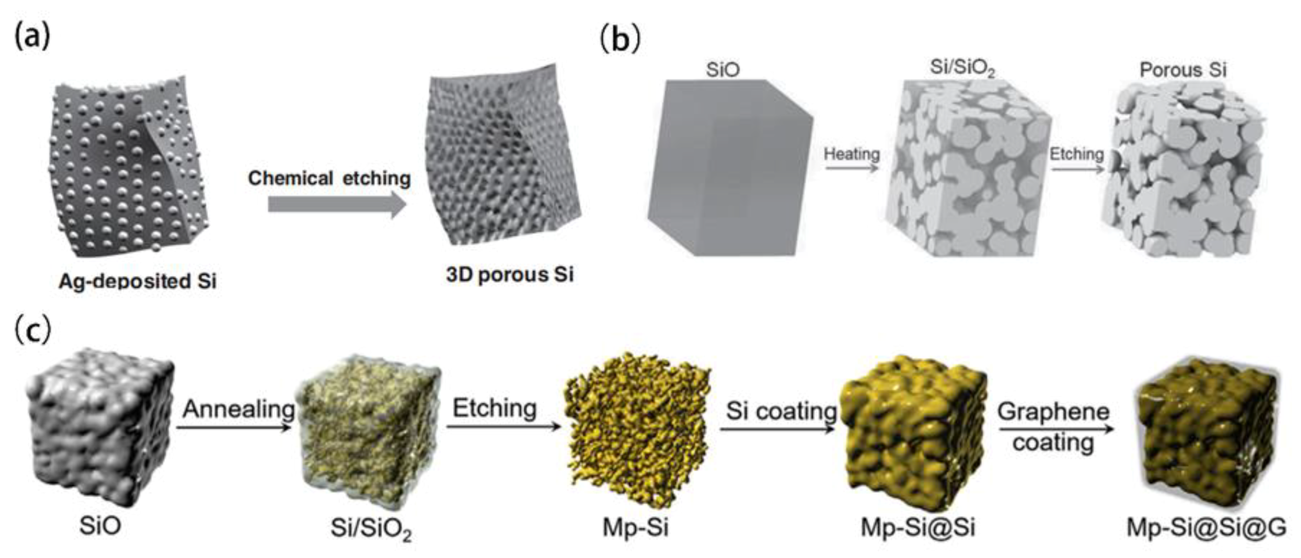
4.2. Porous Silicon by Self-Reorganization

Porous silicon by self-reorganization is the porous structure produced during converting silicon-containing precursors into silicon, such as the conversion of SiO2 into Si. Wang et al. [74] converted the silica spheres prepared by the Stober method into highly monodisperse porous silicon nanospheres (MPSNs) through NaCl added magnesothermic reduction reaction (MRR). MPSNs as an anode of LIBs demonstrated a reversible capacity of 1500 mA·h·g−1 after 500 cycles at 0.5 C. Xiang et al. [75] proved that using Mg2Si as a magnesium source instead of Mg powder and SiO2 nanospheres as reactants, porous silicon spheres can also be prepared. Compared to the traditional MRR using Mg powder as the reactant, the improved method provided good control of heat release and thus to get a stable pore structure. Silicon is the second abundant element in the earth and often exists in the form of SiO2 in nature. It is one of the ideal routes to direct using natural resources containing SiO2 to produce porous silicon for LIB. Favors et al. [76] used beach sands as the silicon source to produce a 3D network of interconnected nanosilicon particles covered by carbon with a thickness of 8–10 nm through the NaCl added MRR process. The carbon coated porous nanosilicon electrode has a capacity of 1024 mA·h·g−1 at 2 A·g−1 after 1000 cycles. Liu et al. [77] constructed a 3D porous silicon (Figure 10b) by reducing the SiO2 in reeds, which showed a good cycling stability that a specific capacity of 420 mA·h·g−1 can be achieved at a rate of 10 C even after 4000 cycles. Rice husks (RHs) are a natural reservoir for nanostructured silica and its derivatives. Using RHs as raw materials, Liu et al. [78] prepared porous Si nanoparticles and demonstrated the good performance as anode for LIBs. Firstly, the organic matters contained in RHs were removed by thermally decomposition, which converted RHs into nano-SiO2, and then MRR on nano-SiO2 was used to produce the porous nano-Si. As the anode materials of LIBs, the porous silicon derived from RHs exhibited a reversible capacity of 2790 mA·h·g−1 and a retention of 86% after 300 cycles. Furthermore, porous silicon (Figure 10c) derived from RHs was used to prepare the composite with RGO [79]. Since an effective three-dimensional conductive network can be formed between silicon particles by RGO. The composite as obtained has a capacity of 907 mA·h·g−1 at 16 A·g−1. Diatomite (DE) has a higher SiO2 content and a unique macroporous structure [80]. The porous silicon [81] owns the specific surface area as high as 296 m2·g−1 had been successfully prepared from DE, and the specific surface area of porous silicon from different silicon sources are shown in Table 1. The DE-based nano Si anodes exhibited a capacity of 1102.1 m·Ah·g−1 after 50 cycles at 0.2 C. On this basis, our group introduced a heat dissipation agent avoiding the side reactions of MRR, to construct a hierarchical porous Si/C composite anode by using DE as the precursor and self-template (Figure 10a,d) [82]. Moreover, Cui et al. [83] successfully prepared a hierarchical mesoporous/macroporous Si/SiO2@C composite material from DE, which with 13% carbon can reach 99.5% after 200 cycles, and the reversible capacity can reach 534.3 mA·h·g−1 at 500 mA·g−1. Through the molten salt-assisted low-temperature aluminothermic reduction technology, Wang et al. [84] prepared nanosilicon assembly microspheres by using diatomite as raw material, which supplied a reversible capacity of 1330.1 mA·h·g−1 at 0.2 A·g−1 after 200 cycles.

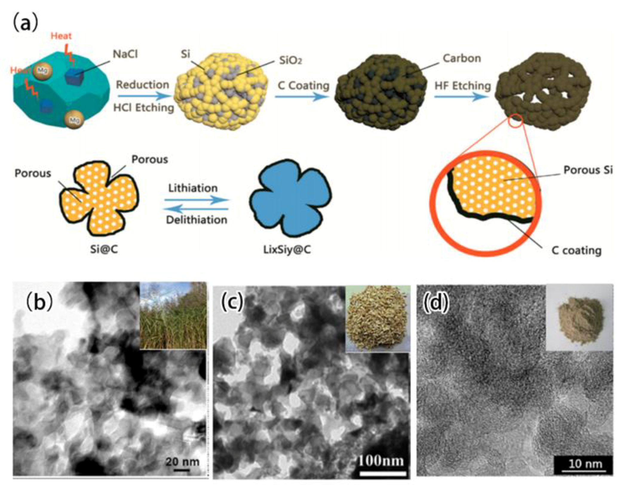
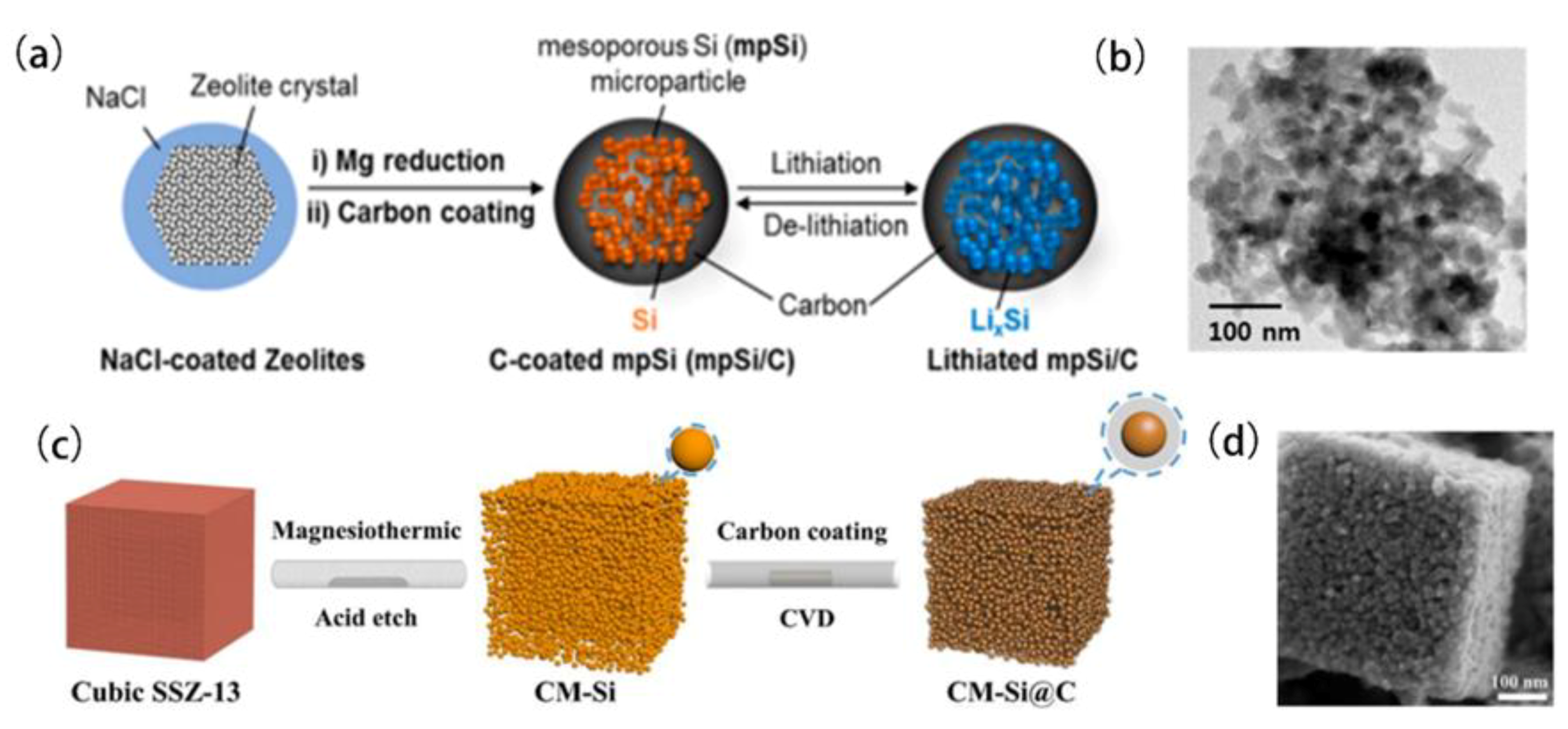
4.3. Porous Structure from the Conversion of Porous Precursor

SiO2 are the most used precursor for producing Si. Based on the low reaction temperature (650 °C) of MRR that is much lower than the melting point of silicon (1410 °C), it is an effective method to prepare a porous silicon based material by reducing the porous SiO2 precursor into Si with a porous structure [85]. Kim et al. [86] firstly synthesized the wrinkled silica nanoparticles (WSN), which then was conversed into a unique high-porosity and canyon-like shape of carbon-coated Si nanoparticles (cpSi@C) through MRR and subsequent carbon deposition. Due to the unique canyon-like surface structure, the fractal transformation of a soft template-based WSN with a large aperture provides additional porosity for Si nanoparticles. The free volume space in the cpSi@C particles is 419% as its Si volume, which is sufficient to accommodate Si volume expansion during cycling. The cpSi@C exhibited a capacity of 822 mA·h·g−1 at 500 mA·g−1 after 200 cycles.
Molecular sieves such as SBA-15 composed of SiO2 have an ordered pore distribution and a 3D interconnected pore structure, it is a good precursor to make porous silicon. By optimizing the condition of MRR of SBA-15, Chen et al. [87] prepared porous silicon with high purity. The porous Si partially kept the channel pore characteristic of SBA-15 and were composed with some tiny nanoparticles. As anode materials of LIBs, it exhibited a reversible capacity of 1004 mA·h·g−1 at 50 mA·g−1 after 50 cycles. To take advantage of carbon nanotubes, Gao et al. [88] first synthesized the porous silicon from KIT-6 template by MRR, and then CNTs were grown onto the porous silicon through an iron catalytic CVD process. The pSi-MWNT combined the good conductivity, flexibleness, high stiffness of carbon nanotubes, and porous structure of silicon, and, thus, exhibited a capacity over 1000 mA·h·g−1 at 300 mA·g−1 after 200 cycles. Furthermore, combining silver nanoparticles and graphene with the porous silicon derived the MCM41 template, Du et al. [89] prepared a graphene-wrapped silver–porous silicon composite, in which Ag nanoparticles were deposited on the surface of mesoporous silicon by utilizing silver mirror reaction and then Ag deposited-porous silicon were covered and wrapped by graphene sheets through reducing the composite of graphene oxide and Ag deposited silicon at 700 °C for 2 h under a 5 vol.% H2/Ar atmosphere. Owing to synergistic effects of Ag nanoparticles enhancing conductivity, graphene improving conductivity and SEI film stability, porous structure of silicon facilitating ions transfer and buffering volumetric expansion, the obtained Ag-pSi/GNS composite exhibited a significantly high capacity, good cycling stability, and excellent rate capability when used as the anode of LIBs. The capacity of 1241 mA·h·g−1 can remain after 50 cycles even at 32 A·g−1. Zeolite sieves own an ordered micropore distribution and have been used as a template to successfully synthesize ordered microporous carbon. However, it is still difficult to get ordered porous silicon by using zeolite as the precursor. Wang et al. [90] reported a high-quality 3D porous (Figure 11c,d) interconnected network of mesoporous silicon sub microcubes composed of Si nanoparticles (5–10 nm) derived from a zeolite SSZ-13 template by a simple and improved MRR method. Using different zeolite as templates, Kim et al. [91] prepared the carbon coated porous silicon (Figure 11a,b), however, the micro-porosity of zeolite was lost after the MRR, the resulted porous silicon presented a broad pore size distribution (19–31 nm) and high pore volume (0.4–0.5 cm3·g−1). As anode of LIBs, the Si derived from zeolite material delivered a capacity of 800–1200 mA·h·g−1 at 500–1000 mA·g−1 with outstanding capacity retention up to 500 cycles.

5. Spatial Structure

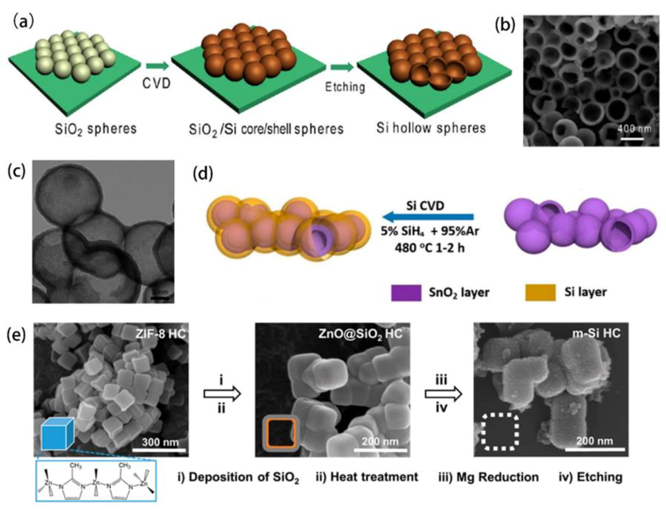
5.1. Hollow Structure of Silicon

The hollow structured silicon can supply a large free space to cushion the volume expansion of silicon based anode during cycles. Yao et al. [92] used the SiO2 sphere as the core template and deposited a silicon layer on the surface of the SiO2 sphere by the CVD technology (Figure 12a,b). By etching the SiO2 core, a novel interconnected Si hollow nanospheres of (SHS) was obtained. The SHS anode achieved an initial discharge capacity of 2725 mA·h·g−1 with the capacity reduction of less than 8% per 100 cycles for a total of 700 cycles. Similarly, using SnO2 as a template to construct the hollow structure is an easier route (Figure 12c,d). Ma et al. [93] prepared the SnO2@Si composite material by coating the Si layer onto the SnO2 template. After removal of SnO2, the SHS can be obtained and exhibited a stable capacity of 1030 mA·h·cm−3 during 500 cycles. Huang et al. [94] used carbonate (CaCO3, Na2CO3, and BaCO3) as a template to prepare hollow silicon in spherical, tubular, and cubic shapes. Chen et al. [95] prepared a porous SiO2 layer onto polystyrene nanoparticles (PS) and then followed by calcination to remove the PS template to construct the hollow structure of SiO2, after the MRR, the porous SiO2 was converted into the hollow Si shell. Ag nanoparticles were composited with hollow Si to further improve the electric conductivity. As anode of LIBs, the material supplied a capacity of 3762 mA·h·g−1 and over 93% capacity retention after 100 cycles. Yoon et al. [96] successfully synthesized mesoporous Si hollow nanocubes (SHC) using the MOF (ZIF-8) as a template (Figure 12e), which is consisted of the mesoporous external shell (~15 nm) of Si and internal void (~60 nm). The SHC with carbon coating supplied the capability of 1050 mA·h g−1 at 15 C and kept the capacity of 850 mA·h·g−1 after 800 cycles at 1 C.

5.2. Silicon Core-Modified Layers Shell Structure

The core-shell structure of silicon core and the surface modification shell is a facile and effective strategy to improve the performance of silicon anode from increasing conductivity, inhibiting volumetric inflation, and stabilizing SEI film [97]. Carbon materials are frequently used as the shell due to their flexibility, good conductivity, and tunability. Chemical vapor deposition (CVD) [98,99] and pyrolytic spraying [100,101] are often used methods to deposit carbon layers around silicon particles. High temperature pyrolysis of carbon precursors such as bitumen and phenolic resins is considered for large scale production of carbon coating due to its relatively simple process [102,103].
In order to obtain a uniform carbon layer as the structured shell, Luo et al. [104] designed and made a microporous carbon coating on silicon nanoparticles to form a uniform coaxial core-shell nanostructure (Figure 13a,b). The authors demonstrated the preparation of a phenolic resin based carbon coating around the surface of silicon nanoparticles by a simple surfactant template sol-gel process. The material as prepared has a carbon layer with a controllable thickness (2–25 nm) and exhibited a capacity of 1006 mA·h·g−1 and a coulombic efficiency of 99.5% after 500 cycles. Polymers have been extensively studied as a surface modification to produce a uniform carbon coating. Polyvinyl alcohol (PVA) [105], polyvinyl chlorideas (PVC) [106], polyvinylidene fluoride (PVDF) [107], polyparaphenylene (PPP) [108] and polystyrene (PS) [109] were coated on silicon nanoparticles and then pyrolized to form the uniform carbon layers. Du et al. [110] dispersed Si nanospheres in distilled water and then wrapped them in soft sodium dodecyl sulfate (SDS). Finally, the polymerization of the pyrrole monomer initiated by the (NH4)2S2O8 oxidant takes place between the soft SDS layer region and the Si spheres, resulting in a uniform polypyrrole (PPy) coating. The PPy@Si electrode demonstrated an excellent cycling stability with 88% capacity retention after 250 cycles. As carbon precursors to make carbon shells, Liu et al. [111] compared the effects of silicon-based core-shell type with polyethylene oxide (PEO), PVC, polyethylene (PE), chlorinated polyethylene (CPE), and PVDF on the property of the resulted carbon layers. It was found that the pyrolysis of PVDF provided an appropriate carbon matrix to buffer the volume effect. The porous composite exhibited a specific capacity of approximately 660 mA·h·g−1 with a 75% capacity retention after 50 cycles. It should be attributed to strong etching by fluorine on silicon during its pyrolysis, which helped to construct a compact interface between Si and the disordered carbon. Yan et al. [112] designed a hierarchical core-shell structure in which silicon particles were encapsulated by a graphene shell, and a conformal carbon shell was introduced to firmly bond the loosely stacked graphene shell and simultaneously seal the nanopores on the surface delivering a high reversible capacity of 1416 mA·h·g−1 at 200 mA·g−1 and 852 mA·h·g−1 at 5 A·g−1, capacity retention of 88.5% could be achieved after 400 cycles at 2 A·g−1. Recently, in order to get a tougher shell inhibiting inflation of Si lithiation, SiO2, TiO2, SiC (Figure 13c,d), SiOx, and TiOx [113,114,115,116,117,118] were used as the shell of core-shell structure, which provided the better structural stability of Si anode during cycles. Maddipatl et al. [119] developed a Si/SiOx@GR anode material. The ultra-thin SiOx layers and highly conductive GR matrix are beneficial to suppress the volume change of silicon, maintain structural integrity, and enhance charge transfer. Therefore Si/SiOx@GR anode owns a good cycling stability. Recently, Pan et al. [120] synthesized a layered porous structure of Si@TiO2@C composite material, the hierarchical porous TiO2 played an effective role on buffering Si expansion during cycles.

5.3. Yolk-Shell Structure

The yolk-shell structure is a novel nano-multiphase composite material with a void between the inner core and the outer shell by etching or removing the sacrificed structure. The composite material exhibits a special Si@void@C yolk-shell configuration. The carbon shell plays as a support framework for the structure and the void space between the nanosilicon particles (SiNP), and the carbon shell allows for the Si-Li alloy to expand without breaking the carbon shell [121].
Liu et al. [122] first proposed the yolk-shell structure that SiNP (Figure 14a) acts as the “yolk” and amorphous carbon plays as the “shell”. Later, Liu and his workmates [123] further synthesized a layered silicon-carbon core-shell composite. When a single silicon nanoparticle is encapsulated by a conductive carbon layer, sufficient expansion and contraction space is left after lithiation and delithiation. Most of these hybrid nanoparticles are then wrapped in a micron sized bag with a thicker carbon layer to serve as an electrolyte barrier. Due to this layered arrangement, the solid electrolyte interface remains stable and the expansion space of Si lithiation keeps limited, therefore the Si based materials as the anode of LIBs exhibited an excellent cycling stability that capacity retention reached 97% after 1000 cycles. Yang et al. [124] replaced the ordinary amorphous carbon shell with a mesoporous carbon shell, which increased the contact area between the electrode and the electrolyte and the Li ions transport efficiency. Sun et al. [125] prepared a Si@SiO2 composite with a yolk-shell structure by a vesicle template method. The SiO2 was used as the outer shell, which can obtain a controlled shell thickness by adjusting the concentration of the surfactant and silicon source. Pan et al. [126] obtained a yolk-shell silicon anode by etching the silicon particles by NaOH solution on the basis of the core-shell structure. According to a similar idea, Wu et al. [127] encapsulated silicon in a hollow carbon tube, leaving an empty space between the Si nanoparticle and the carbon tube. The obtained anode has a capacity retention rate of 90% after 200 cycles.
SiO2 as a stable sacrificial structure has been proved to be able to successfully construct the free space between the carbon shell and the silicon core. However, the etching process requires the use of HF or NaOH solution with strong oxidability reagents. Using the template easy to be removed including magnesium oxide (MgO), calcium carbonate (CaCO3), and alumina (Al2O3) as sacrificial structures have been demonstrated to prepare the silicon anodes with yolk-shell structure [128,129,130]. Xie et al. [131] synthesized Si/C microsphere with voids and holes via the polymerization-induced colloid aggregation (PICA) method. Wang et al. [132] reported a facile templateless approach for preparing Si@void@C materials through controlling the growth kinetics of resin (Figure 14c). The Si@void@C as prepared delivered a large of capacity 1993.2 mA·h·g−1 at 100 mA·g−1 and 799.4 mA·h·g−1 at 10 A·g−1, respectively, capacity retention reached 73.5% at 2.0 A·g−1 after 1000 cycles. Furthermore, Xie et al. [133] constructed the Si@C@void@C spatial structure for the first time by coating the carbon layer before coating the sacrificial layer. The Si@C@void@C structure is derived from the Si@void@C structure. The extra carbon shell not only reduces the electrical resistance between the silicon and the carbon shell, but also effectively protects the silicon from electrolyte corrosion The Si@C@void@C electrode showed significantly enhanced cycle stability with a capacity of 1366 mA·h·g−1 after 50 cycles at 500 mA·g−1. Huang et al. [134] designed a method for constructing a Si@C@void@C structure using polystyrene (PS) and polyaniline (PAni) as the sources generating pore and shell, respectively. PS was grown on the surface of Si nanoparticles and then PAni was coated to form Si@PS@PAni. Due to the significant difference in carbon yield of PS and PAni during calcination, the carbonization of PS is removed leaving and produced the thin carbon layers as inner shells and left void spaces between carbon layers and Si, while PAni was carbonized to form outer C shells, resulting in the formation of Si@C@void@C materials. Yang et al. [135] first reported the synthesis of Si@void@SiO2@void@C nanostructures by selectively etching SiO2 in the Si@SiO2@C structure, and the new structure included a hard silica coating, a conductive carbon layer, and two internal void spaces to confine and accommodate the volume expansion of silicon. In the structure, the carbon layer can improve electrical conductivity, the silica layer has mechanical strength for inhibiting the volume expansion, and the two internal void spaces can limit and accommodate the volumetric expansion of silicon lithiation. Meanwhile, a uniform conductive carbon layer can establish a stable SEI on its outer surface for dual protection. Therefore, these specially designed double-shell structures exhibited a stable capacity of 956 mA·h·g−1 and a capacity retention rate of 83% after 430 cycles. Liu et al. [136] also introduced a SiO2 layer into the yolk-shell structure and made a fully integrated silicon-based anode (Figure 14b). By the multi-component interconnect between the carbon spheres, the cross-linked carboxymethyl cellulose, and citric acid polymer binder. The fully integrated Si@SiO2@void@C electrode owned the higher mechanical strength. And exhibited an excellent cycling stability. It supplied a capacity of 1640 mA·h·g−1 at 1 A·g−1, a capacity retention rate of 84.6% after 1000 cycles even at 5 A·g−1 rate.

6. Conclusions and Prospects

The advantages, problems, and technologies to improve silicon as the anode of LIBs are reviewed and commented on. The critical factors of structured space and pore design to improve the cycle stability of silicon based anode materials are systematically discussed and summarized.
Silicon nanoparticles are produced to cope with the pulverization caused by the volume expansion of silicon during cycles, but the interaction stress between the particles makes them separated from the current collector. One-dimensional nano-structured silicon was designed from nanowires and nanotubes which can improve stability of silicon anode by preventing the electrode from cracking caused by the volume expansion of silicon. However, the complicated preparation process and high cost make it difficult to be commercially applied. Therefore, it requires more and deeper study from lowering the cost of raw materials to simplifying technology.
The hollow and hierarchical porous structure of silicon and carbon were successfully constructed and exhibited the significantly enhanced durability when being used in the anode of LIBs. The drawback is unsatisfying volumetric capacity, since the spaces from the hollow structure or pores cannot supply any capacity for lithium ions storage. Moreover, some of the hollow space and pores were produced through etching templates by using the matters with strong oxidability, which bring the risks to pollute the environment. In future works, it needs to consider how to balance the volumetric capacity and structure space for alleviating the volume inflation. In addition, the agents and processes with environmental friendliness must be developed.
Surface modification is a facile and effective strategy to improve the performance of silicon-based anode from increasing conductivity, inhibiting volumetric inflation to stabilizing SEI film. By using carbon materials with good conductivity and flexibility, the modifications of carbon coatings and graphene’s encapsulation on silicon had shown a significant improvement in the performance of the anode. The yolk-shell structure (Si@void@C) can combine the above technical advantages. The carbon shell serves as the supporting frame and conductive network. The void space between the silicon nanoparticles and the carbon shell allows the Si-Li alloy to expand without destroying the carbon shell, ensuring that the stability of the overall structure of the material and the formation of a stable SEI film during charge-discharge process. It must be emphasized that a strong interaction between the modified layer and silicon is the critical factor to keep the integration of silicon-based material, which is very important for getting the anode with good durability.
Although many significant signs of progress on solving the volumetric effects of silicon lithiation and delithiation have been achieved, which supplies us the considerable routes to get silicon anode with a good performance, there still are some important factors influencing the actual application of silicon as the anode of LIBs needed to be studied. Apart from the electrochemical performance, simplifying technology, lowing the cost, and owning environmental friendliness of the preparation process must be considered and are very important for developing the applicable silicon-based anode for LIBs.

Author Contributions

Conceptualization, Y.C., L.L. and B.A.; Methodology, F.D.; Validation, W.Z., H.Y., C.S., X.G. and Z.L.; Writing—Original Draft Preparation, F.D.; Writing—Review & Editing, Y.C., L.L. and B.A. All authors have read and agreed to the published version of the manuscript.

Funding

Financial supports by the NSFC No. 51972156, 51672117, 51872131, 51672118 and Distinguished Professor of Liaoning Province (2017) are acknowledged.

Institutional Review Board Statement

Not applicable.

Informed Consent Statement

Not applicable.

Data Availability Statement

Not applicable.

Conflicts of Interest

The authors declare no conflict of interest.

References

  1. King, D. Global clean energy in 2017. Science 2017, 355, 111. [Google Scholar] [CrossRef] [Green Version]
  2. Zhang, C.; Wang, F.; Han, J.; Bai, S.; Tan, J.; Liu, J.; Li, F. Challenges and recent progress on silicon-based anode materials for next-generation lithium-ion batteries. Small Struct. 2021, 2, 2100009–2100027. [Google Scholar] [CrossRef]
  3. Yu, B.C.; Hwa, Y.; Kim, J.H.; Sohn, H.J. Carbon coating for Si nanomaterials as high-capacity lithium battery. Electrochem. Commun. 2014, 46, 144–147. [Google Scholar] [CrossRef]
  4. Armand, M.; Tarascon, J.M. Building better batteries: Researchers must find a sustainable way of providing the power our modern lifestyles demand. Nature 2008, 451, 652–657. [Google Scholar] [CrossRef]
  5. Wu, F.; Maier, J.; Yu, Y. Guidelines and trends for next-generation rechargeable lithium and lithium-ion batteries. Chem. Soc. Rev. 2020, 49, 1569–1614. [Google Scholar] [CrossRef]
  6. Tarascon, J.M.; Armand, M. Issues and challenges facing rechargeable lithium batteries. Nature 2001, 414, 359–367. [Google Scholar] [CrossRef] [PubMed]
  7. Higgins, T.M.; Park, S.H.; King, P.J.; Zhang, C.; McEvoy, N.; Berner, N.C.; Daly, D.; Shmeliov, A.; Khan, U.; Duesberg, G. A commercial conducting polymer as both binder and bonductive additive for silicon nanoparticle-based lithium-ion battery negative electrodes. ACS Nano 2016, 10, 3702–3713. [Google Scholar] [CrossRef]
  8. Zhang, Y.; Du, N.; Yang, D. Designing superior solid electrolyte interfaces on silicon anodes for high-performance lithium-ion batteries. Nanoscale 2019, 11, 19086–19104. [Google Scholar] [CrossRef] [PubMed]
  9. Bie, Y.; Yang, J.; Lu, W.; Lei, Z.; Nuli, Y.; Wang, J. A Facile 3D binding approach for high Si loading anodes. Electrochim. Acta 2016, 212, 141–146. [Google Scholar] [CrossRef]
  10. Yao, W.; Chen, J.; Zhan, L.; Wang, Y.; Yang, S. Two-dimensional porous sandwich-like C/Si-graphene-Si/C nanosheets for superior lithium storage. ACS Appl. Mater. Interfaces 2017, 9, 39371–39379. [Google Scholar] [CrossRef] [PubMed]
  11. Abel, P.A.; Lin, Y.M.; Celio, H.; Heller, A.; Mullins, B.C. Improving the stability of nanostructured silicon thin film lithium-ion battery anodes through their controlled oxidation. ACS Nano 2012, 6, 2506–2516. [Google Scholar] [CrossRef]
  12. Lin, C.T.; Huang, T.Y.; Huang, J.J.; Wu, N.L.; Leung, M. Multifunctional Co-poly (amic acid): A new binder for Si-based micro-composite anode of lithium-ion battery. J. Power Sources 2016, 330, 246–252. [Google Scholar] [CrossRef]
  13. Song, J.; Zhou, M.; Yi, R.; Xu, T.; Gordin, M.L.; Tang, D.; Yu, Z.; Regula, M.; Wang, D. Interpenetrated gel polymer binder for high-performance silicon anodes in lithium-ion batteries. Adv. Funct. Mate. 2014, 24, 5904–5910. [Google Scholar] [CrossRef]
  14. Ding, X.; Liu, X.X.; Huang, Y.; Zhang, X.; Zhao, Q.; Xiang, X.; Li, G.; He, P.; Wen, Z.; Li, J. Enhanced electrochemical performance promoted by monolayer graphene and void space in silicon composite anode materials. Nano Energy 2016, 27, 647–657. [Google Scholar] [CrossRef]
  15. Shan, X.; Cao, Z.; Zhu, G.; Wang, Y.; Qu, Q.; Liu, G.; Zheng, H. A trimethylol melamine functionalized polyvinyl alcohol network for high performance nano-silicon anodes. J. Mater. Chem. A 2019, 7, 26029–26038. [Google Scholar] [CrossRef]
  16. Stevenson, K.J. Role of surface oxides in the formation of solid electrolyte interphases at silicon electrodes for lithium-ion batteries. ACS Appl. Mater. Interfaces 2014, 6, 21510–21524. [Google Scholar]
  17. Liu, X.H.; Huang, J.Y. In situ TEM electrochemistry of anode materials in lithium ion batteries. Energy Environ. Sci. 2011, 4, 3844–3860. [Google Scholar] [CrossRef]
  18. Chen, Y.; Du, N.; Zhang, H.; Yang, D. Facile synthesis of uniform MWCNT@Si nanocomposites as high-performance anode materials for lithium-ion batteries. J. Alloys Compd. 2015, 622, 966–972. [Google Scholar] [CrossRef]
  19. Wu, X.L.; Guo, Y.G.; Wan, L.J. Rational design of anode materials based on group IVA elements (Si, Ge, and Sn) for lithium-ion batteries. Chem. Asian J. 2013, 8, 1948–1958. [Google Scholar] [CrossRef]
  20. Yang, Y.; Yuan, W.; Kang, W.; Ye, Y.; Pan, Q.; Zhang, X.; Ke, Y.; Wang, C.; Qiu, Z.; Tang, Y. A review on silicon-nanowires-based anodes for next-generation high-performance lithium-ion batteries from a material-based perspective. Sustain. Energy Fuels 2020, 4, 1577–1594. [Google Scholar] [CrossRef]
  21. Chan, C.K.; Peng, H.; Gao, L.; Mcilwrath, K.; Xiao, F.Z.; Huggins, R.A.; Yi, C. High-performance lithium battery anodes using silicon nanowires. Nat. Nanotechnol. 2007, 3, 31–35. [Google Scholar] [CrossRef]
  22. Cui, L.F.; Ruffo, R.; Chan, C.K.; Peng, H.; Cui, Y. Crystalline-amorphous core shell silicon nanowires for high capacity and high current battery electrodes. Nano Lett. 2009, 9, 491–495. [Google Scholar] [CrossRef]
  23. Ruffo, R.; Hong, S.S.; Chan, C.K.; Huggins, R.A.; Cui, Y. Impedance analysis of silicon nanowire lithium ion battery anodes. J. Phys. Chem. C 2009, 113, 11390–11398. [Google Scholar] [CrossRef] [Green Version]
  24. Wang, B.; Li, X.; Zhang, X.; Luo, B.; Jin, M.; Liang, M. Adaptable silicon-carbon nanocables sandwiched between reduced graphene oxide sheets as lithium ion battery anodes. ACS Nano 2013, 7, 1437–1445. [Google Scholar] [CrossRef]
  25. Song, H.; Wang, S.; Song, X.; Yang, H.; Du, G.; Yu, L.; Xu, J.; He, P.; Zhou, H.; Chen, K. A bottom-up synthetic hierarchical buffer structure of copper silicon nanowire hybrids as ultra-stable and high-rate lithium-ion battery anodes. J. Mater. Chem. A 2018, 6, 7877–7886. [Google Scholar] [CrossRef]
  26. Wen, Z.; Lu, G.; Mao, S.; Kim, H.; Cui, S.; Yu, K.; Huang, X.; Hurley, P.T.; Mao, O.; Chen, J. Silicon nanotube anode for lithium-ion batteries. Electrochem. Commun. 2013, 29, 67–70. [Google Scholar] [CrossRef]
  27. Park, M.H.; Kim, M.G.; Joo, J.; Kim, K.; Kim, J.; Ahn, S. Silicon nanotube battery anodes. Nano Lett. 2009, 9, 3844–3847. [Google Scholar] [CrossRef]
  28. Song, T.; Xia, J.; Lee, J.H.; Lee, D.H.; Kwon, M.S.; Choi, J.M.; Wu, J.; Doo, S.K.; Chang, H.; Park, W.; et al. Arrays of sealed silicon nanotubes as anodes for lithium ion batteries. Nano Lett. 2010, 10, 1710–1716. [Google Scholar] [CrossRef]
  29. Song, T.; Cheng, H.; Choi, H.; Lee, J.H.; Han, H.; Lee, D.H.; Yoo, D.S.; Kwon, M.S.; Choi, J.M.; Doo, S.G.; et al. Si/Ge double-layered nanotube array as a lithium ion battery anode. ACS Nano 2012, 6, 303–309. [Google Scholar] [CrossRef]
  30. Wu, H.; Chan, G.; Choi, J.W.; Ryu, I.; Yao, Y.; Mcdowell, M. Stable cycling of double-walled silicon nanotube battery anodes through solid-electrolyte interphase control. Nat. Nanotechnol. 2012, 7, 310–315. [Google Scholar] [CrossRef]
  31. Kwon, Y.; Park, G.S.; Cho, J. Synthesis and electrochemical properties of lithium-electroactive surface-stabilized silicon quantum dots. Electrochim. Acta 2007, 52, 4663–4668. [Google Scholar] [CrossRef]
  32. Wang, G.X.; Yao, J.; Liu, H.K. Characterization of nanocrystalline Si-MCMB composite anode materials. Electrochem. Solid. State Lett. 2004, 7, A250–A253. [Google Scholar] [CrossRef]
  33. Magasinski, A.; Dixon, P.; Hertzberg, B.; Kvit, A.; Ayala, J.; Yushin, G. High-performance lithium-ion anodes using a hierarchical bottom-up approach. Nat. Mater. 2010, 9, 461. [Google Scholar] [CrossRef]
  34. Zhu, R.; Hu, X.; Chen, K.; Dang, J.; Wang, X.; Liu, X.; Wang, H. Double-shelled hollow carbon nanospheres as enclosed electrochemical reactors to enhance the lithium storage performance of silicon nanodots. J. Mater. Chem. A 2020, 8, 12502–12517. [Google Scholar] [CrossRef]
  35. Yang, J.; Wang, B.F.; Wang, K.; Liu, Y.; Xie, J.Y.; Wen, Z.S. Si/C composites for high capacity lithium storage materials. Electrochem. Solid. State Lett. 2003, 6, A154–A156. [Google Scholar] [CrossRef]
  36. Jo, Y.N.; Kim, Y.; Kim, J.S.; Song, J.H.; Kim, K.J.; Chong, Y.K.; Lee, D.J.; Park, C.W.; Kim, Y.J. Si-graphite composites as anode materials for lithium secondary batteries. J. Power Sources 2010, 195, 6031–6036. [Google Scholar] [CrossRef]
  37. Ma, C.; Ma, C.; Wang, J.; Wang, H.; Shi, J.; Song, Y.; Guo, L.; Liu, L. Exfoliated graphite as a flexible and conductive support for si-based li-ion battery anodes. Carbon 2014, 72, 38–46. [Google Scholar] [CrossRef]
  38. Park, J.; Kim, G.P.; Nam, I.; Park, S.; Yi, J. One-pot synthesis of silicon nanoparticles trapped in ordered mesoporous carbon for use as an anode material in lithium-ion batteries. Nanotechnology 2013, 24, 25602–25608. [Google Scholar] [CrossRef]
  39. Zhang, R.; Du, Y.; Li, D.; Shen, D.; Yang, J.; Guo, Z.; Liu, H.; Elzatahry, A.; Zhao, D. Highly reversible and large lithium storage in mesoporous Si/C nanocomposite anodes with silicon nanoparticles embedded in a carbon framework. Adv. Mater. 2014, 26, 6749–6754. [Google Scholar] [CrossRef]
  40. Zeng, L.; Liu, R.; Han, L.; Luo, F.; Chen, X.; Wang, J.; Qian, Q.; Chen, Q.; Wei, M. Preparation of a Si/SiO2–ordered-mesoporous-carbon nanocomposite as an anode for high-Performance lithium-ion and sodium-ion batteries. Chem. Eur. J. 2018, 24, 1–9. [Google Scholar] [CrossRef]
  41. Gao, R.; Tang, J.; Yu, X.; Tang, S.; Ozawa, K.; Sasaki, T.; Qin, L.C. In situ synthesis of MOF-derived carbon shells for silicon anode with improved lithium-ion storage. Nano Energy 2020, 70, 104444. [Google Scholar] [CrossRef]
  42. Zhang, C.; Park, S.H.; Ascaso, A.S.; Barwich, S.; McEvoy, N.; Boland, C.S.; Coleman, J.N.; Gogotsi, Y.; Nicolosi, V. High capacity silicon anodes enabled by MXene viscous aqueous ink. Nat. Commun. 2019, 10, 849–857. [Google Scholar] [CrossRef] [Green Version]
  43. Xia, M.; Chen, B.; Gu, F.; Zu, L.; Xu, M.; Feng, Y.; Wang, Z.; Zhang, H.; Zhang, C.; Yang, J. Ti3C2Tx MXene nanosheets as a robust and conductive tight on Si anodes significantly enhance electrochemical lithium storage performance. ACS Nano 2020, 14, 5111–5120. [Google Scholar] [CrossRef]
  44. Gómez-Cámer, J.L.; Morales, J.; Sánchez, L. Anchoring Si nanoparticles to carbon nanofibers: An efficient procedure for improving Si performance in Li batteries. J. Mater. Chem. 2010, 21, 811–818. [Google Scholar] [CrossRef]
  45. Zhang, M.; Hou, X.H.; Wang, J.; Li, M.; Hu, S.J.; Shao, Z.P.; Liu, X. Interweaved Si@C/CNTs&CNFs composites as anode materials for Li-ion batteries. J. Alloys Compd. 2014, 588, 206–211. [Google Scholar]
  46. Liu, R.P.; Shen, C.; Dong, Y.; Qin, J.L.; Wang, Q.; Iocozzia, J.; Zhao, S.Q.; Yuan, K.J.; Han, C.P.; Lie, B.H.; et al. Sandwich-like CNTs/Si/C nanotubes as high performance anode materials for lithium-ion batteries. J. Mater. Chem. A 2018, 6, 14797–14804. [Google Scholar] [CrossRef]
  47. Zhang, L.; Wang, C.; Dou, Y.; Cheng, N.; Cui, D.; Du, Y.; Liu, P.; Mamun, M.; Zhang, S.; Zhao, H. A yolk–shell structured silicon anode with superior conductivity and high tap density for full lithium-ion batteries. Angew. Chem. Int. Ed. 2019, 58, 8824–8828. [Google Scholar] [CrossRef] [PubMed]
  48. Jia, P.; Li, X.; Song, J.; Zhang, X.; Luo, L.; He, Y.; Li, B.; Cai, Y.; Hu, S.; Xiao, X.; et al. Hierarchical porous silicon structures with extraordinary mechanical strength as high-performance lithium-ion battery anodes. Nat. Commun. 2020, 11, 1474–1482. [Google Scholar] [CrossRef] [Green Version]
  49. Wang, H.; Fu, J.; Wang, C.; Wang, J.; Yang, A.; Li, C.; Sun, Q.; Cui, Y.; Li, H. A binder-free high silicon content flexible anode for Li-ion batteries. Energy Environ. Sci. 2020, 13, 848–858. [Google Scholar] [CrossRef]
  50. Zhao, X.; Hayner, C.M.; Kung, M.C.; Kung, H.H. In-plane vacancy-enabled high-power Si-graphene composite electrode for lithium-ion batteries. Adv. Energy Mater. 2011, 1, 1079–1084. [Google Scholar] [CrossRef]
  51. Liu, X.; Zhang, J.; Si, W.; Xi, L.; Eichler, B.; Yan, C. Sandwich nanoarchitecture of Si/reduced graphene oxide bilayer nanomembranes for li-ion batteries with long cycle life. ACS Nano 2015, 9, 1198–1205. [Google Scholar] [CrossRef]
  52. Mori, T.; Chen, C.J.; Hung, T.F.; Mohamed, S.G.; Lin, Y.Q.; Lin, H.Z.; Sung, J.C.; Hu, S.F. High specific capacity retention of graphene/silicon nanosized sandwich structure fabricated by continuous electron beam evaporation as anode for lithium-ion batteries. Electrochim. Acta 2015, 165, 166–172. [Google Scholar] [CrossRef]
  53. Luo, J.; Zhao, X.; Wu, J.; Jang, H.D.; Kung, H.H.; Huang, J. Crumpled graphene-encapsulated Si nanoparticles for lithium ion battery anodes. J. Phys. Chem. Lett. 2012, 3, 1824–1829. [Google Scholar] [CrossRef]
  54. Jamaluddin, A.; Umesh, B.; Chen, F.; Chang, J.K.; Su, C.Y. Facile synthesis of core-shell structured Si@graphene balls as a high-performance anode for lithium-ion batteries. Nanoscale 2020, 12, 9616–9627. [Google Scholar] [CrossRef]
  55. Chabot, V.; Feng, K.; Park, H.W.; Hassan, F.M.; Elsayed, A.R.; Yu, A. Graphene wrapped silicon nanocomposites for enhanced electrochemical performance in lithium ion batteries. Electrochim. Acta 2014, 130, 127–134. [Google Scholar] [CrossRef]
  56. Zhao, G.; Zhang, L.; Meng, Y.; Zhang, N.; Sun, K. Decoration of graphene with silicon nanoparticles by covalent immobilization for use as anodes in high stability lithium ion batteries. J. Power Sources 2013, 240, 212–218. [Google Scholar] [CrossRef]
  57. Son, I.H.; Park, J.H.; Kwon, S.; Park, S.; Rümmeli, M.H.; Bachmatiuk, A.; Song, H.J.; Ku, J.; Choi, J.W.; Choi, J.M. Silicon carbide-free graphene growth on silicon for lithium-ion battery with high volumetric energy density. Nat. Commun. 2015, 6, 7393–7400. [Google Scholar] [CrossRef] [PubMed] [Green Version]
  58. Liu, X.; Lu, J.; Jiang, J.; Jiang, Y.; Zhang, J. Enhancing lithium storage performance by strongly binding silicon nanoparticles sandwiching between spherical graphene. Appl. Surf. Sci. 2021, 539, 148191–148199. [Google Scholar] [CrossRef]
  59. Wang, F.; Hu, Z.; Mao, L.; Mao, J. Nano-silicon@soft carbon embedded in graphene scaffold: High-performance 3D free-standing anode for lithium-ion batteries. J. Power Sources 2020, 450, 227692–227701. [Google Scholar] [CrossRef]
  60. Ge, M.; Lu, Y.; Ercius, P.; Rong, J.; Fang, X.; Mecklenburg, M.; Zhou, C. Large-scale fabrication, 3D tomography, and lithium-ion battery application of porous silicon. Nano Lett. 2013, 14, 261–268. [Google Scholar] [CrossRef]
  61. Kim, J.S.; Choi, W.; Cho, K.Y.; Byun, D.; Lim, J.C.; Lee, J.K. Effect of polyimide binder on electrochemical characteristics of surface-modified silicon anode for lithium ion batteries. J. Power Sources 2013, 244, 521–526. [Google Scholar] [CrossRef]
  62. Bang, B.M.; Lee, J.; Kim, H.; Cho, J.; Park, S. High-performance macroporous bulk silicon anodes synthesized by template-free chemical etching. Adv. Energy. Mater. 2012, 2, 878–883. [Google Scholar] [CrossRef]
  63. Zhang, Z.; Wang, Y.; Ren, W.; Tan, Q.; Chen, Y.; Li, H.Z.; Zhong, Z.; Su, F. Scalable synthesis of interconnected porous silicon/carbon composites by the rochow reaction as high-performance anodes of lithium ion batteries. Angew. Chem. Int. Ed. 2014, 53, 5165–5169. [Google Scholar]
  64. Zhang, Z.; Wang, Y.; Ren, W.; Tan, Q.; Zhong, Z.; Su, F. Low-cost synthesis of porous silicon via ferrite-assisted chemical etching and their application as Si-based anodes for Li-ion batteries. Adv. Electron. Mater. 2015, 1, 1400059–1400066. [Google Scholar] [CrossRef]
  65. Ren, W.; Wang, Y.; Zhang, Z.; Tan, Q.; Zhong, Z.; Su, F. Carbon-coated porous silicon composites as high performance Li-ion battery anode materials: Can the production process be cheaper and greener? J. Mater. Chem. A. 2016, 4, 552–560. [Google Scholar] [CrossRef]
  66. Kim, H.; Han, B.; Choo, J.; Cho, J. Three-dimensional porous silicon particles for use in high-performance lithium secondary batteries. Angew. Chem. Int. Ed. 2010, 47, 10151–10154. [Google Scholar] [CrossRef]
  67. Yi, R.; Dai, F.; Gordin, M.L.; Chen, S.; Wang, D. Micro-sized Si-C composite with interconnected nanoscale building blocks as high-performance anodes for practical application in lithium-ion batteries. Adv. Energy. Mater. 2013, 3, 273–278. [Google Scholar] [CrossRef]
  68. Wang, J.; Liao, L.; Lee, H.; Shi, F.; Huang, W.; Zhao, W.; Pei, A.; Tang, J.; Zeng, X.; Chen, W.; et al. Surface-engineered mesoporous silicon microparticles as high-Coulombic efficiency anodes for lithium-ion batteries. Nano Energy 2019, 61, 404–410. [Google Scholar] [CrossRef]
  69. An, W.; He, P.; Xiao, C.; Guo, E.; Pang, C.; He, X.; Ren, J.; Yuan, G.; Du, N.; Yang, D. Hierarchical carbon shell compositing microscale silicon skeleton as high-performance anodes for lithium-ion batteries. ACS Appl. Energy Mater. 2021, 4, 4976–4985. [Google Scholar] [CrossRef]
  70. Ngo, D.T.; Le, H.; Pham, X.M.; Jung, J.W.; Vu, N.H.; Fisher, J.G. Highly porous coral-like silicon particles synthesized by an ultra-simple thermal-reduction method. J. Mater. Chem. A 2018, 6, 1–3. [Google Scholar] [CrossRef]
  71. Zhang, Y.; Du, N.; Chen, Y.; Lin, Y.; Jiang, J.; He, Y. Carbon dioxide as green carbon source for synthesis of carbon cages encapsulating porous silicon as high performance lithium-ion battery anodes. Nanoscale 2018, 10, 5626–5633. [Google Scholar] [CrossRef] [PubMed]
  72. An, W.; Gao, B.; Mei, S.; Xiang, B.; Fu, J.; Wang, L.; Zhang, Q.; Chu, P.; Huo, K. Scalable synthesis of ant-nest-like bulk porous silicon for high-performance lithium-ion battery anodes. Nat. Commun. 2019, 10, 1447–1457. [Google Scholar] [CrossRef] [Green Version]
  73. Zhou, J.; Zhou, L.; Yang, L.; Chen, T.; Li, J.; Pan, H.; Yang, Y.; Wang, Z. Carbon free silicon/polyaniline hybrid anodes with 3D conductive structures for superior lithium-ion batteries. Chem. Commun. 2020, 56, 2328–2331. [Google Scholar] [CrossRef] [PubMed]
  74. Wei, W.; Favors, Z.; Ionescu, R.; Ye, R.; Bay, H.H.; Ozkan, M. Monodisperse porous silicon spheres as anode materials for lithium ion batteries. Sci. Rep. 2015, 5, 8781–8786. [Google Scholar]
  75. Xiang, B.; An, W.L.; Fu, J.J.; Mei, S.X.; Guo, S.G.; Zhang, X.; Gao, B.; Chu, P. Graphene-encapsulated blackberry-like porous silicon nanospheres prepared by modest magnesiothermic reduction for high-performance lithium-ion battery anode. Rare Met. 2020, 40, 1–10. [Google Scholar] [CrossRef]
  76. Favors, Z.; Wang, W.; Bay, H.H.; Mutlu, Z.; Ahmed, K.; Liu, C.; Ozkan, M.; Ozkan, C.S. Scalable synthesis of nano-silicon from beach sand for long cycle life li-ion batteries. Sci. Rep. 2014, 4, 5623–5629. [Google Scholar] [CrossRef] [Green Version]
  77. Liu, J.; Kopold, P.; Aken, P.A.; Maier, J.; Yu, Y. Energy storage materials from nature through nanotechnology: A sustainable route from reed plants to a silicon anode for lithium ion batteries. Angew. Chem. Int. Ed. 2015, 127, 9632–9636. [Google Scholar] [CrossRef]
  78. Liu, N.; Huo, K.; Mcdowell, M.T.; Jie, Z.; Cui, Y. Rice husks as a sustainable source of nanostructured silicon for high performance li-ion battery anodes. Sci. Rep. 2013, 3, 1919–1925. [Google Scholar] [CrossRef]
  79. Jiao, L.S.; Liu, J.Y.; Li, H.Y.; Wu, T.S.; Li, F.; Wang, H.Y.; Niu, L. Facile synthesis of reduced graphene oxide-porous silicon composite as superior anode material for lithium-ion battery anodes. J. Power Sources 2016, 315, 9–15. [Google Scholar] [CrossRef]
  80. Shen, L.; Guo, X.; Fang, X.; Wang, Z.; Chen, L. Magnesiothermically reduced diatomaceous earth as a porous silicon anode material for lithium ion batteries. J. Power Sources 2012, 213, 229–232. [Google Scholar] [CrossRef]
  81. Wei, L.; Wang, X.; Meyers, C.; Wannenmacher, N.; Ji, X. Efficient fabrication of nanoporous Si and Si/Ge enabled by a heat scavenger in magnesiothermic reactions. Sci. Rep. 2013, 3, 2222–2228. [Google Scholar]
  82. Di, F.; Wang, N.; Li, L.; Geng, X.; Yang, H.; Zhou, W.; Sun, C.; An, B. Coral-like porous composite material of silicon and carbon synthesized by using diatomite as self-template and precursor with a good performance as anode of lithium-ion battery. J. Alloys Compd. 2020, 854, 157253–157260. [Google Scholar] [CrossRef]
  83. Yu, H.; Cui, M.; Wang, L.; Guo, X.; Wang, E.; Yang, Y.; Wu, T.; He, D.; Liu, S.; Yu, H. Design hierarchical mesoporous/macroporous silicon-based composite anode material for low-cost high-performance lithium-ion batteries. J. Mater. Chem. A 2019, 7, 3874–3881. [Google Scholar]
  84. Wang, D.; Zhang, D.; Dong, Y.; Lin, R.; Liu, X.; Li, A.; Chen, X.; Song, H. Reconstructed nano-Si assembled microsphere via molten salt-assisted low-temperature aluminothermic reduction of diatomite as high-performance anodes for lithium-ion batteries. ACS Appl. Energy Mater. 2021, 4, 6146–6153. [Google Scholar] [CrossRef]
  85. Bao, Z.; Weatherspoon, M.R.; Shian, S.; Cai, Y.; Graham, P.D.; Allan, S.M.; Ahmad, G.; Dickerson, M.B.; Church, B.C.; Kang, Z.; et al. Chemical reduction of three-dimensional silica micro-assemblies into microporous silicon replicas. Nature 2007, 38, 172–175. [Google Scholar] [CrossRef] [PubMed]
  86. Kim, B.; Ahn, J.; Oh, Y.; Tan, J.; Lee, D.; Lee, J.; Moon, J. Highly porous carbon-coated silicon nanoparticles with canyon-like surfaces as a high-performance anode material for Li-ion batteries. J. Mater. Chem. A 2018, 6, 3028–3037. [Google Scholar] [CrossRef]
  87. Chen, W.; Fan, Z.; Dhanabalan, A.; Chen, C.; Wang, C. Mesoporous silicon anodes prepared by magnesiothermic reduction for lithium ion batteries. J. Electrochem. Soc. 2011, 158, A1055–A1059. [Google Scholar] [CrossRef]
  88. Gao, P.; Jia, H.; Yang, J.; Nuli, Y.; Wang, J.; Chen, J. Three-dimensional porous silicon-MWNT heterostructure with superior lithium storage performance. Phys. Chem. Chem. Phys. 2011, 13, 20108–20111. [Google Scholar] [CrossRef]
  89. Du, F.H.; Wang, K.X.; Fu, W.; Gao, P.F.; Wang, J.F.; Yang, J.; Chen, J.S. A graphene-wrapped silver–porous silicon composite with enhanced electrochemical performance for lithium-ion batteries. J. Mater. Chem. A 2013, 1, 13648–13654. [Google Scholar] [CrossRef]
  90. Wang, B.; Li, W.; Wu, T.; Guo, J.; Wen, Z. Self-template construction of mesoporous silicon submicrocube anode for advanced lithium ion batteries. Energy Storage Mater. 2018, 17, 139–147. [Google Scholar] [CrossRef]
  91. Kim, N.; Park, H.; Yoon, N.; Lee, K. Zeolite-templated mesoporous silicon particles for advanced lithium-ion battery anodes. ACS Nano 2018, 12, 3853–3864. [Google Scholar] [CrossRef]
  92. Yao, Y.; Mcdowell, M.T.; Ryu, I.; Wu, H.; Liu, N.; Hu, L.; Nix, W.D.; Cui, Y. Interconnected silicon hollow nanospheres for lithium-ion battery anodes with long cycle life. Nano Lett. 2011, 11, 2949–2954. [Google Scholar] [CrossRef] [PubMed]
  93. Ma, T.; Yu, X.; Li, H.; Zhang, W.; Cheng, X.; Zhu, W.; Qiu, X. High volumetric capacity of hollow structured SnO2@Si nanospheres for lithium-ion batteries. Nano Lett. 2017, 17, 3959–3964. [Google Scholar] [CrossRef] [PubMed]
  94. Huang, X.; Yang, J.; Mao, S.; Chang, J.; Hallac, P.B.; Fell, C.R.; Metz, B.; Jiang, J.; Hurley, P.T.; Chen, J. Controllable synthesis of hollow Si anode for long-cycle life lithium-ion batteries. Adv. Mater. 2014, 26, 4326–4332. [Google Scholar] [CrossRef]
  95. Chen, D.; Mei, X.; Ge, J.; Lu, M.; Xie, J.; Lu, J.; Lee, Y. Reversible lithium-ion storage in silver-treated nanoscale hollow porous silicon particles. Angew. Chem. Int. Ed. 2012, 51, 2409–2413. [Google Scholar] [CrossRef]
  96. Yoon, T.; Bok, T.; Kim, C.; Na, Y.; Park, S.; Kim, K.S. Mesoporous silicon hollow nanocubes derived from metal–organic framework template for advanced lithium-ion battery anode. ACS Nano 2017, 11, 4808–4815. [Google Scholar] [CrossRef] [PubMed]
  97. Kim, Y.S.; Kim, K.W.; Cho, D.; Hansen, N.S.; Lee, J.; Joo, Y.L. Silicon-rich carbon hybrid nanofibers from water-based spinning: The synergy between silicon and carbon for li-ion battery anode application. Chemelectrochem 2014, 1, 220–226. [Google Scholar] [CrossRef]
  98. Dimov, N.; Kugino, S.; Yoshio, M. Carbon-coated silicon as anode material for lithium ion batteries: Advantages and limitations. Electrochim. Acta. 2003, 48, 1579–1587. [Google Scholar] [CrossRef]
  99. Dimov, N.; Fukuda, K.; Umeno, T.; Kugino, S.; Yoshio, M. Characterization of carbon-coated silicon: Structural evolution and possible limitations. J. Power Sources 2003, 114, 88–95. [Google Scholar] [CrossRef]
  100. Ng, S.H.; Wang, J.; Wexler, D.; Konstantinov, K.; Guo, Z.P.; Liu, H.K. Highly reversible lithium storage in spheroidal carbon-coated silicon nanocomposites as anodes for lithium-ion batteries. Angew. Chem. Int. Ed. 2006, 45, 6896–6899. [Google Scholar] [CrossRef]
  101. Ng, S.H.; Wang, J.; Konstantinov, K.; Wexler, D.; Chew, S.Y.; Guo, Z.P.; Liu, H.K. Spray-pyrolyzed silicon/disordered carbon nanocomposites for lithium-ion battery anodes. J. Power Sources 2007, 174, 823–827. [Google Scholar] [CrossRef]
  102. Wen, Z.S.; Yang, J.; Wang, B.F.; Wang, K.; Liu, Y. High capacity silicon/carbon composite anode materials for lithium ion batteries. Electrochem. Commun. 2003, 5, 165–168. [Google Scholar] [CrossRef]
  103. Shen, L.; Wang, Z.; Chen, L. Carbon-coated hierarchically porous silicon as anode material for lithium ion batteries. RSC Adv. 2014, 4, 15314–15318. [Google Scholar] [CrossRef]
  104. Luo, W.; Wang, Y.; Chou, S.; Xu, Y.; Li, W.; Kong, B. Critical thickness of phenolic resin-based carbon interfacial layer for improving long cycling stability of silicon nanoparticle anodes. Nano Energy 2016, 27, 255–264. [Google Scholar] [CrossRef] [Green Version]
  105. Liu, Y.; Hanai, K.; Yang, J.; Imanishi, N.; Hirano, A.; Takeda, Y. Morphology-stable silicon-based composite for li-intercalation. Solid State Ionics. 2004, 168, 61–68. [Google Scholar] [CrossRef]
  106. Xu, Y.H.; Yin, G.P.; Ma, Y.L.; Zuo, P.J.; Cheng, X.Q. Nanosized core/shell silicon@carbon anode material for lithium ion batteries with polyvinylidene fluoride as carbon source. J. Mater. Chem. 2010, 20, 3216–3220. [Google Scholar] [CrossRef]
  107. Zhang, X.W.; Patil, P.K.; Wang, C.; Appleby, A.J.; Little, F.E.; Cocke, D.L. Electrochemical performance of lithium ion battery, nano-silicon-based, disordered carbon composite anodes with different microstructures. J. Power Sources 2004, 125, 206–213. [Google Scholar] [CrossRef]
  108. Em, I.S.; Kumta, P.N. High capacity Si/C nanocomposite anodes for li-ion batteries. J. Power Sources 2004, 136, 145–149. [Google Scholar]
  109. Feng, M.; Tian, J.; Xie, H.; Kang, Y.; Shan, Z. Nano-silicon/polyaniline composites with an enhanced reversible capacity as anode materials for lithium ion batteries. J. Solid. State. Electrochem. 2015, 19, 1773–1782. [Google Scholar] [CrossRef]
  110. Du, F.H.; Li, B.; Fu, W.; Xiong, Y.J.; Wang, K.X.; Hen, J. Surface binding of polypyrrole on porous silicon hollow nanospheres for li-ion battery anodes with high structure stability. Adv. Mater. 2014, 26, 6145–6150. [Google Scholar] [CrossRef]
  111. Liu, Y.; Wen, Z.Y.; Wang, X.Y. Electrochemical behaviors of Si/C composite synthesized from F-containing precursors. J. Power Sources 2009, 189, 733–737. [Google Scholar] [CrossRef]
  112. Yan, Y.; Xu, Z.; Liu, C.; Dou, H.; Wei, J.; Zhao, X.; Ma, J.; Dong, Q.; Xu, H.; He, Y.; et al. Rational design of robust janus shell on silicon anodes for high performance lithium ion batteries. ACS Appl. Mater. Interfaces 2019, 11, 17375–17383. [Google Scholar] [CrossRef]
  113. Tao, H.C.; Yang, X.L.; Zhang, L.L.; Ni, S.B. Double-walled core-shell structured Si@SiO2@C nanocomposite as anode for lithium-ion batteries. Ionics 2014, 20, 1547–1552. [Google Scholar] [CrossRef]
  114. Hu, G.; Yu, R.; Liu, Z.; Yu, Q.; Zhang, Y.; Chen, Q.; Wu, J.; Zhou, L.; Mai, L. Surface oxidation layer-mediated conformal carbon coating on Si nanoparticles for enhanced lithium storage. ACS Appl. Mater. Interfaces 2021, 13, 3991–3998. [Google Scholar] [CrossRef] [PubMed]
  115. Fang, S.; Shen, L.; Xu, G.; Nie, P.; Wang, J.; Dou, H.; Zhang, X. Rational design of void-involved Si@TiO2 nanospheres as high-performance anode material for lithium-ion batteries. ACS Appl. Mater. Interfaces 2014, 6, 6497–6503. [Google Scholar] [CrossRef] [PubMed]
  116. Ngo, D.T.; Le, H.; Pham, X.M.; Park, C.N.; Park, C.J. Facile synthesis of Si@SiC composite as an anode material for lithium-ion batteries. ACS Appl. Mater. Interfaces 2017, 9, 32790–32800. [Google Scholar] [CrossRef]
  117. Yu, Y.; Gang, L.; Xu, C.; Lin, W.; Rong, J.; Yang, W. Rigid TiO2−x coated mesoporous hollow Si nanospheres with high structure stability for lithium-ion battery anodes. RSC Adv. 2018, 8, 15094–15101. [Google Scholar] [CrossRef] [Green Version]
  118. Wen, Z.; Lu, G.; Cui, S.; Kim, H.; Ci, S.; Jiang, J.; Hurley, K.; Chen, J. Rational design of carbon network cross-linked Si-SiC hollow nanosphere as anode of lithium-ion batteries. Nanoscale 2013, 6, 342–351. [Google Scholar] [CrossRef]
  119. Maddipatl, R.; Lok, C.; Lee, K.S. Electrochemical performance of an ultrathin surface oxide modulated nano-Si anode confined in a graphite matrix for highly reversible lithium-ion batteries. ACS Appl. Mater. Interfaces 2020, 12, 54608–54618. [Google Scholar] [CrossRef] [PubMed]
  120. Pan, Q.; Zhao, J.; Xing, B.; Jiang, S.; Pang, M.; Qu, W.; Zhang, S.; Zhang, Y.; Zhao, L.; Liang, W. A hierarchical porous architecture of silicon@TiO2@carbon composite novel anode materials for high performance Li-ion batteries. New J. Chem. 2019, 43, 15342–15350. [Google Scholar] [CrossRef]
  121. Ru, Y.; Evans, D.G.; Zhu, H.; Yang, W. Facile fabrication of yolk–shell structured porous Si–C microspheres as effective anode materials for Li-ion batteries. RSC Adv. 2014, 4, 71–75. [Google Scholar] [CrossRef]
  122. Liu, N.; Wu, H.; Mcdowell, M.T.; Yao, Y.; Wang, C.; Cui, Y. A yolk-shell design for stabilized and scalable li-ion battery alloy anodes. Nano Lett. 2012, 12, 3315–3321. [Google Scholar] [CrossRef] [PubMed] [Green Version]
  123. Liu, N.; Lu, Z.; Zhao, J.; McDowell, M.T.; Lee, H.-W.; Zhao, W.; Cui, Y. A pomegranate-inspired nanoscale design for large-volume-change lithium battery anodes. Nat. Nanotechnol. 2014, 9, 187–192. [Google Scholar] [CrossRef] [PubMed]
  124. Yang, J.; Wang, Y.; Chou, S.; Zhang, R.; Xu, Y.; Fan, J.; Zhang, W.; Liu, H.K.; Zhao, D.; Dou, S.X. Yolk-shell silicon-mesoporous carbon anode with compact solid electrolyte interphase film for superior lithium-ion batteries. Nano Energy 2015, 18, 133–142. [Google Scholar] [CrossRef] [Green Version]
  125. Sun, Z.; Song, X.; Zhang, P.; Gao, L. Controlled synthesis of yolk-mesoporous shell Si@SiO2 nanohybrid designed for high performance li ion battery. RSC Adv. 2014, 4, 20814–20820. [Google Scholar] [CrossRef]
  126. Pan, L.; Wang, H.; Gao, D.; Chen, S.; Tan, L.; Lei, L. Facile synthesis of yolk–shell structured Si–C nanocomposites as anodes for lithium-ion batteries. Chem. Commun. 2014, 50, 5878–5880. [Google Scholar] [CrossRef] [Green Version]
  127. Wu, H.; Zheng, G.; Liu, N.; Carney, T.J.; Yang, Y.; Cui, Y. Engineering empty space between Si nanoparticles for lithium-ion battery anodes. Nano Lett. 2012, 12, 904–909. [Google Scholar] [CrossRef] [Green Version]
  128. Ma, Y.; Tang, H.; Zhang, Y.; Li, Z.; Zhang, X.; Tang, Z. Facile synthesis of Si-C nanocomposites with yolk-shell structure as an anode for lithium-ion batteries. J. Alloys Compd. 2017, 704, 599–606. [Google Scholar] [CrossRef] [Green Version]
  129. Zhang, L.; Rajagopalan, R.; Guo, H.; Hu, X.; Dou, S.; Liu, H. A green and facile way to prepare granadilla-like silicon-based anode materials for li-ion batteries. Adv. Funct. Mater. 2016, 26, 440–446. [Google Scholar] [CrossRef] [Green Version]
  130. Du, F.H.; Zhou, N.Y.; Wang, Y.; Wang, D.; Ge, Q.; Chen, S.; Yang, H.Y. Green fabrication of silkworm cocoon-like silicon-based composite for high-performance li-ion batteries. ACS Nano 2017, 11, 8628–8650. [Google Scholar] [CrossRef] [PubMed]
  131. Xie, C.; Xu, Q.; Sari, H.M.K.; Li, X. Elastic buffer structured Si/C microsphere anodes via polymerization-induced colloid aggregation. Chem. Commun. 2020, 56, 6770–6773. [Google Scholar] [CrossRef]
  132. Wang, F.; Wang, B.; Ruan, T.; Gao, T.; Dou, S. Construction of structure-tunable Si@void@C anode materials for lithium-ion batteries through controlling the growth kinetics of resin. ACS Nano 2019, 13, 12219–12229. [Google Scholar] [CrossRef]
  133. Xie, J.; Tong, L.; Su, L.; Xu, Y.; Wang, L.; Wang, Y. Core-shell yolk-shell Si@C@void@C nanohybrids as advanced lithium ion battery anodes with good electronic conductivity and corrosion resistance. J. Power Sources 2017, 342, 529–536. [Google Scholar] [CrossRef]
  134. Huang, X.; Sui, X.; Yang, H.; Ren, R.; Wu, Y.; Guo, X.; Chen, J. Hf-free synthesis of Si/C yolk/shell anodes for lithium-ion batteries. J. Mater. Chem. A 2018, 6, 2593–2601. [Google Scholar] [CrossRef]
  135. Yang, L.Y.; Li, H.Z.; Liu, J.; Sun, Z.Q.; Tang, S.S.; Lei, M. Dual yolk-shell structure of carbon and silica-coated silicon for high-performance lithium-ion batteries. Sci. Rep. 2015, 5, 10908–10916. [Google Scholar] [CrossRef] [Green Version]
  136. Liu, Y.; Tai, Z.; Zhou, T.; Sencadas, V.; Zhang, J.; Zhang, L.; Konstantinov, K.; Guo, Z.; Liu, H.K. An all-integrated anode via interlinked chemical bonding between double-shelled-yolk-structured silicon and binder for lithium-ion batteries. Adv. Mater. 2017, 29, 1703028.1–1703028.11. [Google Scholar] [CrossRef]
Figure 1. Schematic diagram of silicon anode material cracking during charge-discharge cycles. The volumetric effect of the silicon-lithium alloy results in high mechanical strain, which causes the silicon anode material to rupture.
Coatings 11 01047 g001
Figure 2. Schematic diagram of formation process of SEI film around the surface of silicon during charge-discharge cycles. The volume effect of silicon-lithium alloy makes it impossible to form a stable SEI film.
Coatings 11 01047 g002
Figure 3. Structure destruction of silicon nanoparticles lose electrical contact during cycles due to stress caused by volumetric effects [19]. Reprinted with permission from [19]. Copyright 2013 John Wiley and Sons.
Coatings 11 01047 g003
Figure 4. (a) Schematic diagram of working principle and TEM images of SiNWs [22]. (b) Schematic diagram of synthesis method and working principle of SiNW@G@RGO anode for LIBs [24]. Reprinted with permission from [22]. Copyright 2009 American Chemical Society. Reprinted with permission from [24]. Copyright 2013 American Chemical Society.
Coatings 11 01047 g004
Figure 5. (a) 3D view of SiNT array anode material and simplified cross-section view before and after electrochemical cycling [28]. (b) TEM images of SiNT/Ge array [29]. Reprinted with permission from [28]. Copyright 2009 American Chemical Society. Reprinted with permission from [29]. Copyright 2012 American Chemical Society.
Coatings 11 01047 g005
Figure 6. (a) Schematic diagram of synthetized silicon-embedded annealed carbon black anode material. (b) SEM micrographs of Si-EG-C electrode after the first discharge (lithium-intercalation) [37]. (c) Schematic diagram and TEM images of Si/OMC composite material with high specific surface area [39]. Reprinted with permission from [37]. Copyright 2014 Elsevier. Reprinted with permission from [39]. Copyright 2014 John Wiley and Sons.
Coatings 11 01047 g006
Figure 7. (a) Schematic diagram of synthetized MWCNTs@Si composite material. (b) TEM images of MWCNTs@Si composite material [18]. (c) 3D view and TEM image of CNT/Si/SiO2/C composite material [47]. Reprinted with permission from [18]. Copyright 2015 Elsevier. Reprinted with permission from [47]. Copyright 2019 John Wiley and Sons.
Coatings 11 01047 g007
Figure 8. (a) Schematic illustration of the preparation process and (b) SEM and (c) TEM image of Si@G anode material by one-step capillary-driven assembly route in aerosol droplets [53]. (d) Schematic illustration of the preparation process and (e) SEM image of GR/Si hollow spherical anode material [58]. Reprinted with permission from [53]. Copyright 2012 American Chemical Society. Reprinted with permission from [58]. Copyright 2021 Elsevier.
Coatings 11 01047 g008
Figure 9. (a) Schematic illustration of the preparation process of porous Si by etching Ag template [62]. (b) Schematic illustration of the preparation process of porous Si by disproportionation reaction of SiO [67]. (c) Schematic illustration of the preparation process of Mp-Si@Si@G sample [68]. Reprinted with permission from [62]. Copyright 2012 John Wiley and Sons. Reprinted with permission from [67]. Copyright 2012 John Wiley and Sons. Reprinted with permission from [68]. Copyright 2019 Elsevier.
Coatings 11 01047 g009
Figure 10. (a) Schematic illustration of the preparation process of porous silicon from diatomite. TEM images of porous silicon from (b) reed [77], (c) rice husk [79], (d) diatomite [82]. Reprinted with permission from [77]. Copyright 2015 John Wiley and Sons. Reprinted with permission from [79]. Copyright 2016 Elsevier. Reprinted with permission from [82]. Copyright 2021 Elsevier.
Coatings 11 01047 g010
Figure 11. (a) Schematic illustration of the preparation process of pSi/C composite from zeolite template. (b) TEM images of pSi/C composite from zeolites template [91]. (c) Schematic illustration of the preparation process and (d) SEM images of CM-Si@C composite from SSZ-13 template [90]. Reprinted with permission from [91]. Copyright 2018 American Chemical Society. Reprinted with permission from [90]. Copyright 2018 Elsevier.
Coatings 11 01047 g011
Figure 12. (a) Schematic illustration of the preparation process (b) SEM image of Si hollow spheres from removing SiO2 spheres [92] (c) TEM image and (d) Schematic illustration of the preparation process of Si hollow spheres from removing SnO2 layer [93]. (e) SEM images illustrating synthetic routes of m-Si HC: (i) Deposition of SiO2 shell coating on ZIF-8 NC, (ii) heat treatment for calcination, (iii) MRR, and (iv) etching with HCl [96]. Reprinted with permission from [92]. Copyright 2011 American Chemical Society. Reprinted with permission from [93]. Copyright 2017 American Chemical Society. Reprinted with permission from [96]. Copyright 2017 American Chemical Society.
Coatings 11 01047 g012
Figure 13. (a) Schematic illustration and (b) TEM images of the fabrication of phenolic resin-based carbon interfacial layer coated commercial silicon nanoparticles through the surfactant template sol-gel approach [104]. (c) Schematic of the synthesis and (d) TEM images of Si@SiC derived from SiO2@C precursors [116]. Reprinted with permission from [104]. Copyright 2016 Elsevier. Reprinted with permission from [116]. Copyright 2017 American Chemical Society.
Coatings 11 01047 g013
Figure 14. (a) 3D view and TEM image of yolk-shell Si@void@C anode material and simplified cross-section view before and after electrochemical cycling [122]. (b) 3D view of Si@SiO2@void@C anode material [136]. (c) Schematic illustration of the preparation process of Si@void@C anode material by the presented templateless method [132]. Reprinted with permission from [122]. Copyright 2012 American Chemical Society. Reprinted with permission from [136]. Copyright 2017 John Wiley and Sons. Reprinted with permission from [132]. Copyright 2019 American Chemical Society.
Coatings 11 01047 g014
Table 1. Specific surfaces area of porous Si from different silicon sources.
PrecursorSilica SphereBeach SandRice HuskDiatomite
Stotal (m2·g−1)215323289296
reference[74][76][78][81]
Publisher’s Note: MDPI stays neutral with regard to jurisdictional claims in published maps and institutional affiliations.

