
Polytetrafluoroethylene Modified Nafion Membranes by Magnetron Sputtering for Vanadium Redox Flow Batteries


State Key Laboratory of Mechanical Transmission, School of Materials Science and Engineering, Chongqing University, Chongqing 400044, China
*
Author to whom correspondence should be addressed.
†
These authors contributed equally to this work.
Coatings 2022, 12(3), 378; https://0-doi-org.brum.beds.ac.uk/10.3390/coatings12030378
Submission received: 8 February 2022
/
Revised: 7 March 2022
/
Accepted: 9 March 2022
/
Published: 14 March 2022
(This article belongs to the Special Issue 10th Anniversary of Coatings: Invited Papers in "Surface Characterization, Deposition and Modification" Section)
Abstract
:Commercial Nafion membranes have been widely used for vanadium redox flow batteries (VRFB) but with relatively low ion selectivity. A chemical method is commonly employed to modify the organic membranes, whereas physical approaches are rarely reported in view of less compatibility with the organic species. In this study, an ultrathin polytetrafluoroethylene (PTFE) film of less than 30 nm is deposited onto the Nafion substrates by radio frequency magnetron sputtering to form PTFE@Nafion composite membranes. The PTFE layer of hydrophobic and inert feature enhances the dimensional stability and the ion selectivity of the Nafion membranes. The VRFB single cell with an optimized composite membrane exhibits a better self-discharge property than that of the Nafion 212 (i.e., 201.2 vs. 18.6 h), due to a higher ion selectivity (i.e., 21.191 × 10⁴ vs. 11.054 × 10⁴ S min cm–3). The composite membranes also show better discharge capacity retention than the Nafion 212 over the entire 100 cycles. The results indicate that the magnetron sputtering is an alternative and feasible route to tailor the organic membranes via surface modification and functionalization.
1. Introduction
The utilization of renewable energies (e.g., wind, solar, and tidal energy) has been the global focus towards sustainable development [1,2,3,4,5]. The intermittent features of renewable energy make it difficult to achieve a reliable energy storage. Vanadium redox flow battery (VRFB) is regarded as one of the most promising systems for large-scale energy storage, considering its long lifetime, fast response, high reliability, low cost, and decoupling of power and capacity [6,7,8]. An ion exchange membrane is a core component in a flow battery to separate the catholyte and anolyte and to conduct protons. The commercial Nafion membranes have been widely employed due to their good conductivity and high chemical and mechanical stability [9,10,11]. However, Nafion membranes generally exhibit large permeability for vanadium ions and thus hinder VRFB development and deployment [12,13,14,15].
To reduce ion permeability and enhance ion selectivity, chemical strategies have been the prevailing approach to modify and improve the Nafion-based membranes, such as sol–gel modification, interfacial polymerization, oxidation polymerization, surfactant treatment, solution casting, and electrodeposition. Sol–gel modification is an effective way to incorporate different additives into the membranes. Xi et al. [16] employed SiO2 nanoparticles to modify Nafion membranes by sol–gel reaction with tetraethyl-orthosilicate. The pores of Nafion membrane were filled with the SiO2 nanoparticles, thus resulting in reduced permeability of vanadium ions. Polymerization is another useful method to introduce organic species. Luo and co-workers [17] synthesized a cationic charged layer on the surface of the Nafion membrane by interfacial polymerization, and Dai et al. [18,19] designed a composite membrane with zwitterionic groups by grafting the sulfobetaine methacrylate onto Nafion membrane via polymerization. The charge repulsion effect and covalent bonds between the additives and matrix suppressed the vanadium ion penetration and enhanced ion selectivity. Solution casting is also feasible to modify the membranes with either organic or inorganic additives. Ye and co-workers [20] used the lignin to blend with Nafion by solution casting, and also [21] incorporated TiO2 nanotubes into the Nafion membranes to achieve high-performance VRFBs. In addition, electrodeposition is also an alternative to tailor the membranes. Zeng et al. [22] modified the Nafion membranes with pyrrole by electrodeposition and revealed an improved property of membrane resistance and vanadium permeability. It is noteworthy that the chemical methods usually require harsh environments and multiple reactions with delicate conditions. To this end, a physical deposition approach is an alternative which is, however, rarely reported due to less compatibility with the organic species.
A physical deposition is a facile and cost-effective way for large-scale surface modification with high-quality thin films, which are generally used for metallic and inorganic species. In this study, a composite membrane of PTFE@Nafion is prepared by radio frequency magnetron sputtering. An ultrathin PTFE layer is deposited onto the Nafion surface and performs as a blocking layer to reduce the permeation of vanadium ions and enhance the dimensional stability of the Nafion membranes for VRFB application.
2. Experimental
The Nafion 212 membranes (DuPont, Wilmington, NC, USA) and PTFE targets (Teflon, purity 99.99%, Shanghai, China) were commercially obtained. The PTFE@Nafion composite membranes were prepared by radio frequency (RF) magnetron sputtering (JPGF-480, Beijing, China) under an argon atmosphere (purity 99.999%). The Nafion membranes were immediately put into the chamber after removing the surface protective layer. The chamber was then pumped down to a vacuum level of less than 3 × 10⁻³ Pa. The distance between the membrane and the target was set as 10 cm. The following major parameters were optimized to adjust the film thickness and surface roughness, i.e., the sputtering power (90, 100, 110, 120, and 130 W), the chamber pressure (0.6, 0.8, 1.0, 1.2, and 1.4 Pa), the substrate temperature (80, 90, 100, 110, and 120 °C), and the deposition time (30, 60, 90, and 120 s). The PTFE films were also sputtered onto the glass substrates (CITOGAS, REF10127105P-G) to determine the film thickness and roughness (Ra) by surface profiler (Dektak 150, Veeco Instruments, Tucson, AZ, USA). Although the film roughness on glasses might exhibit some deviations from that on Nafion membranes, it could be used to optimize the sputtering conditions.
The morphologies of composite membranes were examined by field emission scanning electron microscopy (FESEM, FEI Nova 400, Hillsboro, OR, USA). The contact angle measurement was performed with an optical tensiometer (Attension Theta, KSVMRI instruments Ltd., Helsinki, Finland) to evaluate the wetting property of the composite membranes. The static contact angle was measured with water droplet (about 5 μL) on the as-deposited composite membranes or the pristine Nafion after removing the protective layer on the surface. The water uptake (WU) was determined by the weight difference between the wet and dry membranes, as follows:
where Wwet and Wdry are the weight of the wet and dry membranes, respectively. Before the water absorption test, the membranes were cut into a size of 2 × 2 cm2 and dried for more than 24 h, and then the weight of dry membrane was measured. Thereafter, the membranes were soaked in deionized water for 12 h, taken out and quickly wiped with absorbent paper to remove the water on the surface, and then the weight of the wet membrane was measured. The swelling ratio (SR) was obtained by calculating the length difference between the wet and dry membranes. The swelling ratio was calculated by:
where Lwet and Ldry are the length of the wet (soaked in deionized water for 12 h) and dry (the as-deposited composite membrane or the pristine Nafion membrane after removing the protective layer on surface) membranes, respectively. The permeability measurement was carried out using a home-made cell, as detailed in our previous report [23]. In brief, the two isolated compartments were filled with 70 mL of 1.5 M VOSO4 in 3.0 M H2SO4 solution and 70 mL of 1.5 M MgSO4 in 3.0 M H2SO4 solution, respectively, which were separated by a composite membrane. The concentration of VO2+ in the MgSO4 compartment was examined with a UV-vis spectrometer (UV-2450PC, Shimadzu, Tokyo, Japan) every 12 h. The permeability (P) can be calculated by [12,17,18]:
where V is the solution volume in the MgSO4 compartment, L and A are the thickness and active area (2.01 cm2) of the membrane, respectively, C0 and Ct are the initial concentration of VO2+ (1.5 M) and the concentration of VO2+ in the MgSO4 compartment as a function of time (t).
The conductivity of the membrane was examined with an electrochemical workstation (CHI660E, Chenhua, Shanghai, China) in a frequency range of 1 Hz–100 KHz. The membrane conductivity (σ) can be calculated by [24,25,26]:
where R1 and R2 are the cell resistance with and without membrane, respectively, which were determined by the intercept at the real axis in a Nyquist plot. The active area was 13.5 cm2 for the conductivity measurement.
A VRFB single cell was assembled as per our previous report [20]. The 15 mL of 1.5 M VO2+ in 3 M H2SO4 and 15 mL of 1.5 M V3+ in 3 M H2SO4 were employed as the catholyte and anolyte, respectively. The PTFE side of a composite membrane was faced to the catholyte to confront the highly corrosive environment. The cell tests were conducted with a battery testing system (CT2001A, LANHE, Wuhan, China). A voltage window of 0.7–1.75 V was used for the cyclic test. An open circuit voltage (OCV) decay of single cell at 75% state of charge (SOC) was recorded beyond 0.85 V.
3. Results and Discussion
3.1. Characterization of Composite Membranes
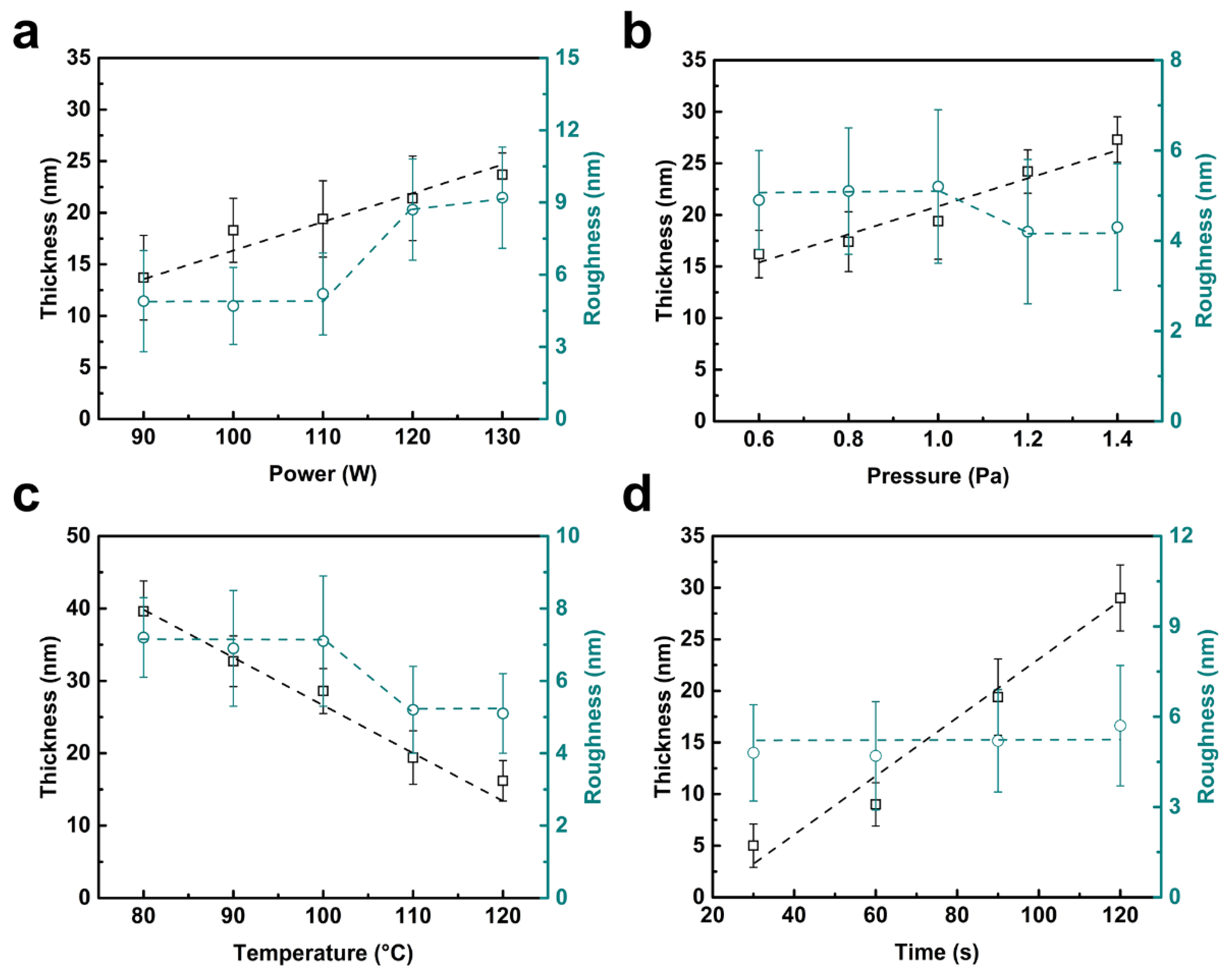
In general, the polytetrafluoroethylene bears a hydrophobic and inert nature. Once formed on the Nafion surface, it behaves as a blocking layer to expel the water molecules and retard the ion permeation. However, the PTFE is also an insulator which, on the other hand, enlarges the membrane’s resistance. As such, the film thickness should be optimized to reach a compromise between the permeability and conductivity. Four important parameters for the RF magnetron sputtering are considered herein, i.e., the sputtering power, chamber pressure, substrate temperature and deposition time. Figure 1 shows that the film thickness generally exhibits a linear relationship with the key parameters. The PTFE thickness increases with the power, as shown in Figure 1a). This is attributed to an enhanced energy of Ar+ ions that generate more PTFE particles with a high deposition rate. Meanwhile, the sputtered particles also bear high energy and tend to form islands on the membrane surface, thus increasing the roughness. An abrupt enhancement arises beyond 110 W for the surface roughness. Accordingly, a sputtering power of 110 W is used for an optimal film deposition. The PTFE thickness displays a similar varying trend with the pressure, as shown in Figure 1b. The quantity of Ar+ ions is promoted under high pressure, resulting in a high deposition rate. However, the average energy of each Ar+ ion is reduced under this scenario because of shortened mean free path for collision. The size of PTFE particles bombarded by Ar+ ions is decreased accordingly, which in turn decreases the film roughness. An optimal pressure of 1.2 Pa is hence selected based on the roughness step presented in Figure 1b. By contrast, the PTFE thickness decreases with the elevated temperature in light of an enhanced evaporation rate of the resulting films, as displayed in Figure 1c. Once reaching the membrane surface, the sputtered PTFE particles can obtain more energy at a high substrate temperature. This facilitates the translational movement of the particles, thereby giving rise to a reduced surface roughness over 110 °C. Consequently, an optimal substrate temperature of 110 °C is chosen herein. With these optimized parameters, the PTFE thickness is tailored to be about 5, 10, 20, and 30 nm by controlling the deposition time of 30, 60, 90, and 120 s, respectively, as shown in Figure 1d. Subsequently, the composite film is referred to as 30PTFE@Nafion, 60PTFE@Nafion, 90PTFE@Nafion, and 120PTFE@Nafion based on the deposition time. The surface roughness remains almost unchanged under the optimal conditions.
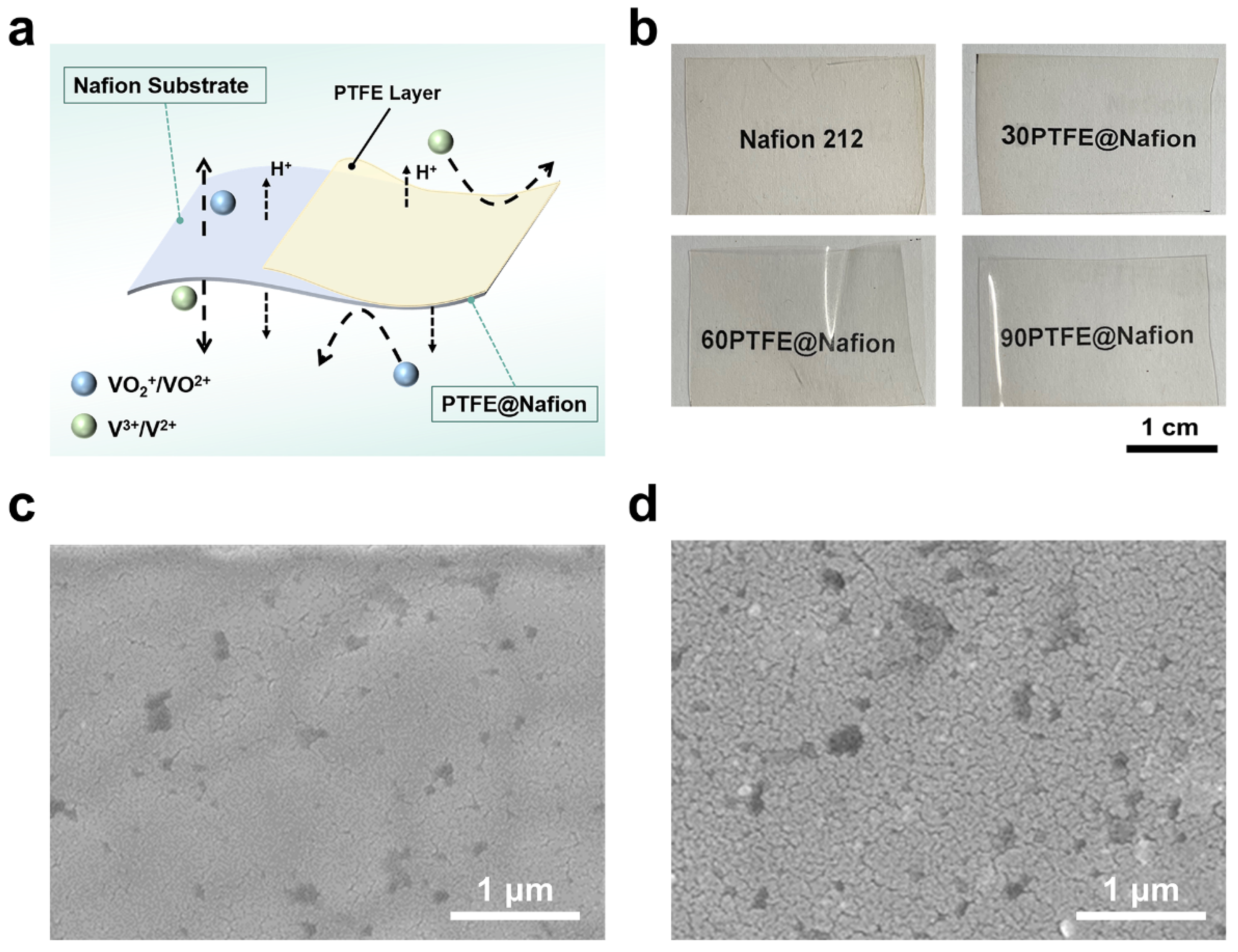
Figure 2a illustrates the microstructure of a PTFE@Nafion composite membrane, where an ultrathin layer of PTFE film is deposited onto the Nafion surface. The PTFE film is expected to suppress the permeation of different vanadium ions and to maintain the transport of protons. Figure 2b displays the photographs of Nafion 212 and PTFE@Nafion membranes. All of the membranes are transparent and show less differences because of the ultrathin films. The corresponding FESEM images of the original and composite membranes reveal that a uniform and porous, thin film is developed on the Nafion substrate, as compared in Figure 2c,d. The porous feature provides the diffusion pathway for both ion permeation and water migration (proton transport) in the operation of VRFB cells, which can be tailored by varying the film thickness. Some small clusters are observed on the composite membrane surface, which stem from the aggregation of PTFE particles. Further examination discloses that the morphologies are almost the same for 60PTFE@Nafion, 90PTFE@Nafion, and 120PTFE@Nafion membranes, while that for 30PTFE@Nafion is not well developed because of the small thickness, as shown in Figure S5.
3.2. Property of Composite Membranes
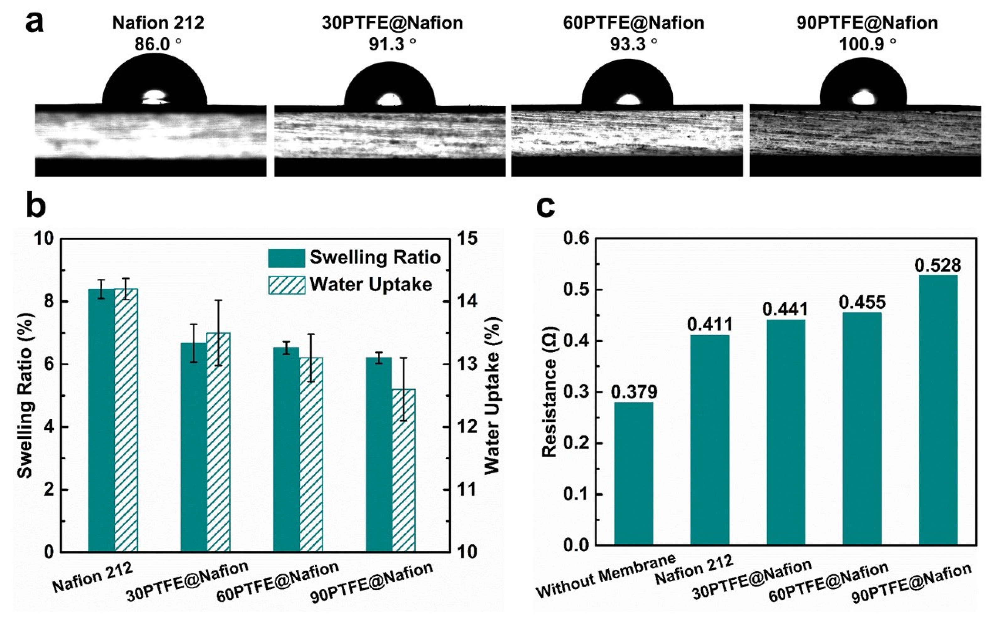
Water contact angle is used to evaluate the surface wettability of the membranes. Figure 3a shows that the contact angle increases with the PTFE thickness due to the hydrophobic nature of polytetrafluoroethylene. Such a hydrophobicity is beneficial to the water repulsion and thus enhances the dimensional stability of membranes. Figure 3b exhibits that the swelling ratio (SR) and water uptake (WU) decline gradually with the increased PTFE thickness, i.e., from 8.4% to 6.2% for SR and from 14.2% to 12.6% for WU. This indicates that the PTFE films can stabilize the Nafion membrane in view of the hydrophobicity. A low swelling ratio also facilitates the PTFE@Nafion membranes to reduce the permeation of vanadium ions and enhance the cyclic stability of flow cells. Nonetheless, the insulating character of PTFE films promotes the membrane resistance, as displayed in Figure 3c. The area resistance increases with the PTFE thickness and is determined to be 0.432, 0.837, 1.026, and 2.012 Ω cm2 with an active area of 13.5 cm2 for Nafion 212, 30PTFE@Nafion, 60PTFE@Nafion, and 90PTFE@Nafion membranes, respectively. (see Figure S6 for corresponding Nyquist plots and detailed interpretation).
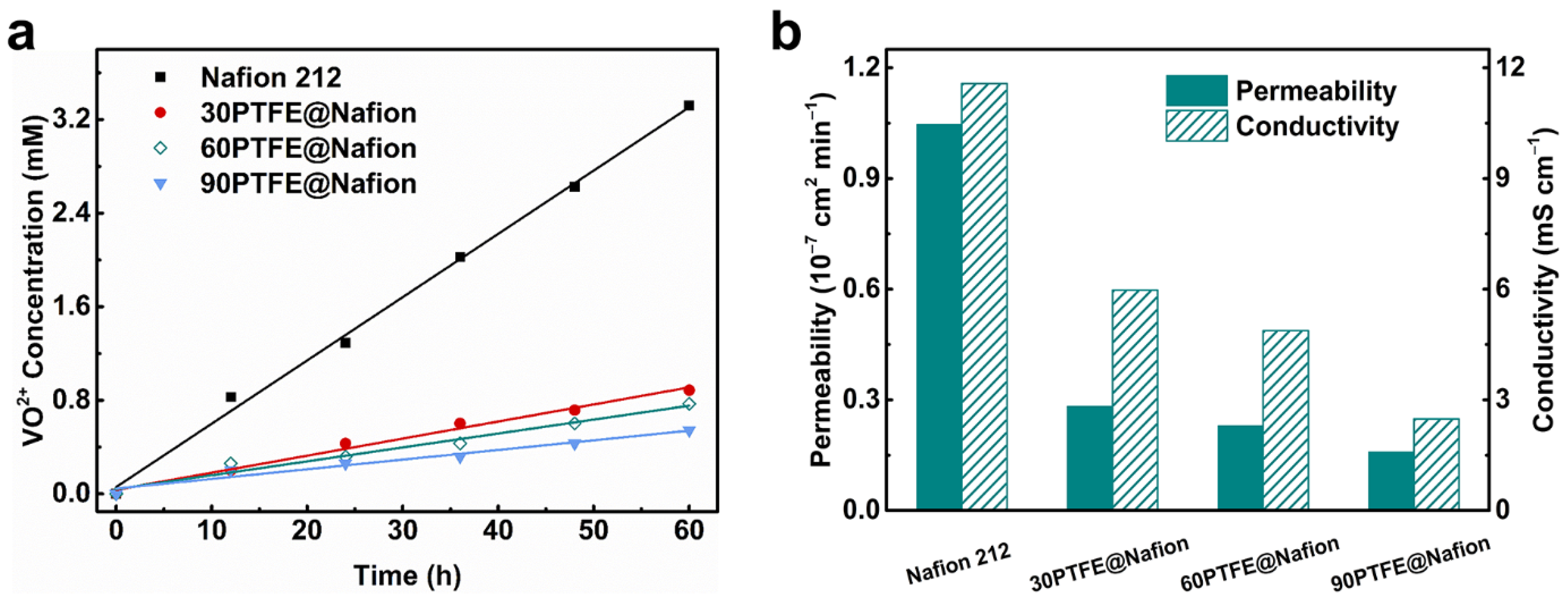
Figure 4a displays the diffusion rate of VO2+ ions for different membranes. Upon coating with the PTFE films, the ion permeation is considerably suppressed with the composite membranes, and the permeation rate decreases with the increased PTFE thickness. This is due to the blocking effect of PTFE layer. The permeability thus declines accordingly, as shown in Figure 4b. On the other hand, the conductivity is also reduced with the increasing film thickness. This suggests that the proton transport is hindered with the PTFE films. Both can be ascribed to the increased diffusion pathway for ion permeation and water migration (proton transport) as the thickness of the porous film increases. In this regard, the ion selectivity (σ/P) is widely used to reach a compromise between the ion permeability and proton conductivity. A high ion selectivity is beneficial to the cell performance. The ion selectivity is hence determined to be 11.054 × 10⁴, 21.109 × 10⁴, 21.191 × 10⁴, and 15.635 × 10⁴ S min cm–3 for Nafion 212, 30PTFE@Nafion, 60PTFE@Nafion, and 90PTFE@Nafion, respectively. Considering the dimensional stability and ion selectivity of the composite membranes, the 60PTFE@Nafion is employed for vanadium redox flow battery.
3.3. Cell Performances
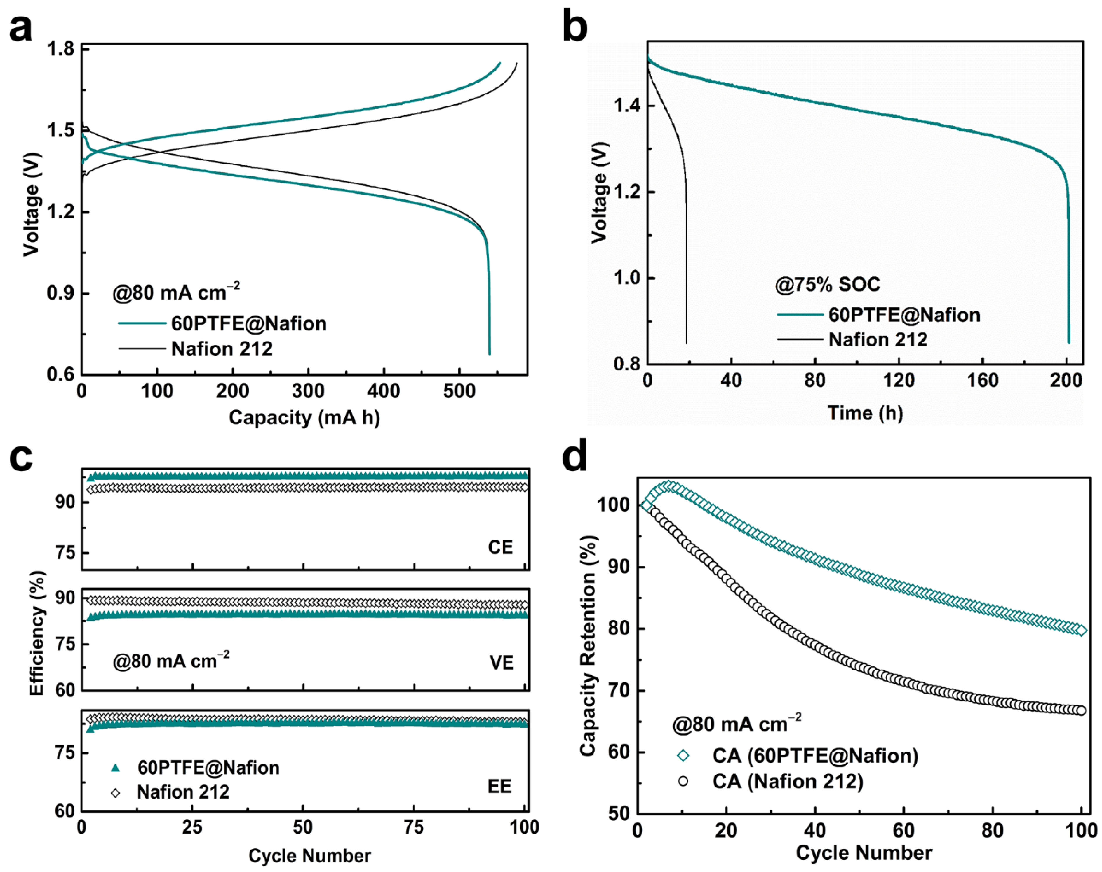
Figure 5a presents the charge–discharge curves of VRFB cells with the Nafion 212 and 60PTFE@Nafion membranes at 80 mA cm–2. Although the charge capacity being a little lower, the single cell with 60PTFE@Nafion membrane exhibits comparable discharge capacity with the Nafion 212. This is attributed to the suppressed permeation of vanadium ions in the presence of PTFE films. The average charge and discharge voltage of 60PTFE@Nafion is not as good as that of the Nafion 212, in light of the enlarged resistance with PTFE layer (see Figure 3c). The OCV decay is used to further investigate the self-discharge property induced by the permeation of vanadium ions. Figure 5b discloses that the OCV decay maintains 201.2 h for the 60PTFE@Nafion membrane, being more than ten-times that for the Nafion 212 counterpart (i.e., 18.6 h). This is in good agreement with the high ion selectivity (i.e., 21.191 × 10⁴ vs. 11.054 × 10⁴ S min cm–3). It demonstrates that the sputtered PTFE films are effective in retarding the crossover of vanadium ions.
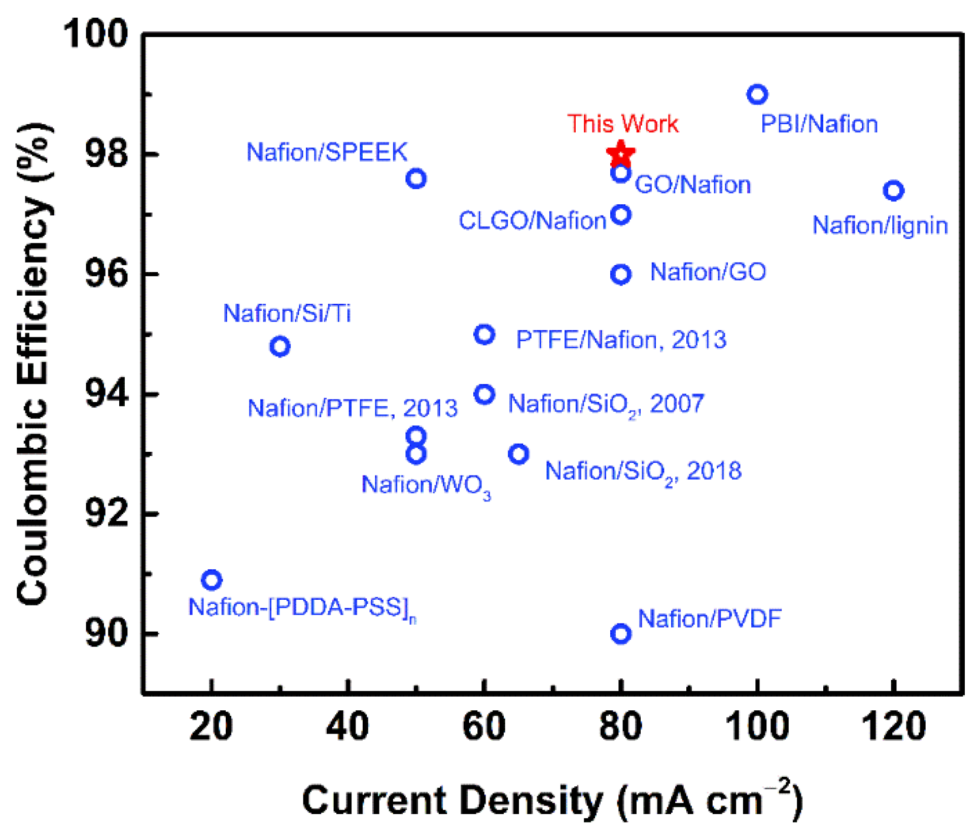
Figure 5c shows a comparison of coulombic, voltage and energy efficiencies between the single cells with 60PTFE@Nafion and Nafion 212 membranes. The coulombic efficiency keeps about 98% for 60PTFE@Nafion membrane and is higher than of the Nafion 212 (i.e., ~94%). This is ascribed to the good ion selectivity with the sputtered PTFE films. The coulombic efficiency even performs better than most of the Nafion-based bulk membranes synthesized by chemical methods, as shown in Figure 6. However, the voltage efficiency of the cell with 60PTFE@Nafion membrane is relatively lower than the Nafion 212 (i.e., 82% vs. 87%), as a result of increased area resistance. Eventually, a comparable energy efficiency is achieved for both membranes. Nevertheless, the discharge capacity retention of the cell with 60PTFE@Nafion membrane performs better than the Nafion 212 over the entire 100 cycles, as displayed in Figure 5d. This originates from the hydrophobic and inert nature of PTFE films that give rise to high dimensional stability and ion selectivity. The major findings herein suggest that the magnetron sputtering approach provides an alternative to modify the organic membranes for VRFB application.
4. Conclusions
A PTFE@Nafion composite membrane is prepared by depositing an ultrathin PTFE film (less than 30 nm) on a Nafion substrate with radio frequency magnetron sputtering. The composite membrane exhibits good dimensional stability and high ion selectivity, due to the hydrophobic and inert nature of the PTFE layer that suppresses the vanadium ion permeation. The 60PTFE@Nafion membrane renders a better self-discharge property than the Nafion 212 counterpart (i.e., 201.2 vs. 18.6 h) in light of higher ion selectivity (i.e., 21.191 × 10⁴ vs. 11.054 × 10⁴ S min cm–3). The VRFB single cell with 60PTFE@Nafion membrane shows better discharge capacity retention than the Nafion 212 over the entire 100 cycles and maintains about 80% at 100 cycles. The major findings indicate that it is feasible and promising to use physical approaches to modify the organic membranes for VRFB application, as compared to the conventional chemical methods.
In addition, there are also some limitations for the method reported herein. (1) The property of the composite membranes is highly dependent on the quality of the sputtering targets. (2) The diversity of organic films is limited by the available sputtering targets. In this regard, more efforts are required to develop sputtering targets of high quality and diversity.
Supplementary Materials
The following supporting information can be downloaded at: https://0-www-mdpi-com.brum.beds.ac.uk/article/10.3390/coatings12030378/s1, Figure S1: Typical surface profiles of PTFE films prepared at different sputtering powers; Figure S2: Typical surface profiles of PTFE films prepared at different chamber pressures; Figure S3: Typical surface profiles of PTFE films prepared at different substrate temperatures; Figure S4: Typical surface profiles of PTFE films prepared at different deposition times; Figure S5: Top-view FESEM images ofdifferent composite membranes; Figure S6: The Nyquist plots for the cells with different membranes.
Author Contributions
Conceptualization, J.S., J.Y. and L.S.; methodology, J.S., J.Y. and Z.Q.; software, J.S.; validation, J.S., J.Y. and L.S.; formal analysis, J.S., J.Y. and L.S.; investigation, J.S. and J.Y.; resources, L.S.; data curation, J.S., J.Y. and Z.Q.; writing—original draft preparation, J.S. and L.S.; writing—review and editing, L.S.; visualization, J.S. and L.S.; supervision, L.S.; project administration, L.S.; funding acquisition, L.S. All authors have read and agreed to the published version of the manuscript.
Funding
The authors are grateful for the financial support from the National Natural Science Foundation of China (51871037), the Natural Science Foundation of Chongqing, China (cstc2021jcyj-jqX0020), the Chongqing Talents: Exceptional Young Talents Project (cstc2021ycjh-bgzxm0063, CQYC201905023), and the National Key Research and Development Program of China (2020YFF0421893).
Institutional Review Board Statement
Not applicable.
Informed Consent Statement
Not applicable.
Data Availability Statement
Data sharing is not applicable to this article.
Conflicts of Interest
The authors declare no conflict of interest.
References
- Xiang, C.; Zhao, X.; Tan, L.; Ye, J.; Wu, S.; Zhang, S.; Sun, L. A solar tube: Efficiently converting sunlight into electricity and heat. Nano Energy 2019, 55, 269–276. [Google Scholar] [CrossRef]
- Tan, R.; Wang, A.; Malpass-Evans, R.; Williams, R.; Zhao, E.W.; Liu, T.; Ye, C.; Zhou, X.; Darwich, B.P.; Fan, Z.; et al. Hydrophilic microporous membranes for selective ion separation and flow-battery energy storage. Nat. Mater. 2020, 19, 195–202. [Google Scholar] [CrossRef] [PubMed]
- Chen, I.S.; Luo, T.; Moon, G.H.; Ogieglo, W.; Kang, Y.S.; Wessling, M. Untra-high proton/vanadium selectivity for hydrophobic polymer membranes with intrinsic nanopores for redox flow battery. Adv. Energy Mater. 2016, 6, 1600517. [Google Scholar]
- Yuan, Z.; Duan, Y.; Zhang, H.; Li, X.; Zhang, H.; Vankelecom, I. Advanced porous membranes with ultra-high selectivity and stability for vanadium flow batteries. Energy Environ. Sci. 2016, 9, 441–447. [Google Scholar] [CrossRef]
- Kim, J.Q.; So, S.; Kim, H.-T.; Choi, S.Q. Highly ordered ultrathin perfluorinated sulfonic acid lonomer membranes for vanadium redox flow battery. ACS Energy Lett. 2021, 6, 184–192. [Google Scholar] [CrossRef]
- Wu, C.; Lu, S.; Wang, H.; Xu, X.; Peng, S.; Tan, Q.; Xiang, Y. A novel polysulfone–polyvinylpyrrolidone membrane with superior proton-to-vanadium ion selectivity for vanadium redox flow batteries. J. Mater. Chem. A 2016, 4, 1174–1179. [Google Scholar] [CrossRef]
- Wu, C.; Bai, H.; Lv, Y.; Lv, Z.; Xiang, Y.; Lu, S. Enhanced membrane ion selectivity by incorporating graphene oxide nanosheet for vanadium redox flow battery application. Electrochim. Acta 2017, 248, 454–461. [Google Scholar] [CrossRef]
- Xia, L.; Long, T.; Li, W.; Zhong, F.; Ding, M.; Long, Y.; Xu, Z.; Lei, Y.; Guan, Y.; Yuan, D.; et al. Highly Stable Vanadium Redox-Flow Battery Assisted by Redox-Mediated Catalysis. Small 2020, 16, 2003321. [Google Scholar] [CrossRef] [PubMed]
- Li, Y.; Lin, X.; Wu, L.; Jiang, C.; Hossain, M.; Xu, T. Quaternized membranes bearing zwitterionic groups for vanadium redox flow battery through a green route. J. Membr. Sci. 2015, 483, 60–69. [Google Scholar] [CrossRef]
- Winardi, S.; Raghu, S.C.; Oo, M.O.; Yan, Q.; Wai, N.; Lim, T.M.; Skyllas-Kazacos, M. Sulfonated poly (ether ether ketone)-based proton exchange membranes for vanadium redox battery applications. J. Membr. Sci. 2014, 450, 313–322. [Google Scholar] [CrossRef]
- Wang, N.; Yu, J.; Zhou, Z.; Fang, D.; Liu, S.; Liu, Y.-N. SPPEK/TPA composite membrane as a separator of vanadium redox flow battery. J. Membr. Sci. 2013, 437, 114–121. [Google Scholar] [CrossRef]
- Semiz, L.; Sankir, N.D.; Sankir, M. Influence of the basic membrane properties of the disulfonated poly(arylene ether sulfone) copolymer membranes on the vanadium redox flow battery performance. J. Membr. Sci. 2014, 468, 209–215. [Google Scholar] [CrossRef]
- Gindt, B.P.; Tang, Z.; Watkins, D.L.; Abebe, D.G.; Seo, S.; Tuli, S.; Ghassemi, H.; Zawodzinski, T.A.; Fujiwara, T. Effects of sulfonated side chains used in polysulfone based PEMs for VRFB separator. J. Membr. Sci. 2017, 532, 58–67. [Google Scholar] [CrossRef] [Green Version]
- Ren, J.; Dong, Y.; Dai, J.; Hu, H.; Zhu, Y.; Teng, X. A novel chloromethylated/quaternized poly(sulfone)/poly(vinylidene fluoride) anion exchange membrane with ultra-low vanadium permeability for all vanadium redox flow battery. J. Membr. Sci. 2017, 544, 186–194. [Google Scholar] [CrossRef]
- Pu, Y.; Huang, X.; Yang, P.; Zhou, Y.; Xuan, S.; Zhang, Y. Effect of non-sulfonated diamine monomer on branched sulfonated polyimide membrane for vanadium redox flow battery application. Electrochim. Acta 2017, 241, 50–62. [Google Scholar] [CrossRef]
- Xi, J.; Wu, W.Z.; Qin, X.; Chen, L. Nafion/SiO2 hybrid membrane for vanadium redox flow battery. J. Power Sources 2007, 166, 531–536. [Google Scholar] [CrossRef]
- Luo, Q.; Zhang, H.; Chen, J.; Qian, P.; Zhai, Y. Modification of Nafion membrane using interfacial polymerization for vanadium redox flow battery applications. J. Membr. Sci. 2008, 311, 98–103. [Google Scholar] [CrossRef]
- Dai, J.; Dong, Y.; Yu, C.; Liu, Y.; Teng, X. A novel Nafion-g-PSBMA membrane prepared by grafting zwitterionic SBMA onto Nafion via SI-ATRP for vanadium redox flow battery application. J. Membr. Sci. 2018, 554, 324–330. [Google Scholar] [CrossRef]
- Dai, J.; Zhang, H.; Sui, Z.; Hu, H.; Gao, P.; Zhu, Y.; Dong, Y.; Teng, X. Study on Nafion/Nafion-g-poly (sulfobetaine methacrylate)-blended amphoteric membranes for vanadium redox flow battery. Ionics 2020, 26, 801–811. [Google Scholar] [CrossRef]
- Ye, J.; Yuan, D.; Ding, M.; Long, Y.; Long, T.; Sun, L.; Jia, C. A cost-effective nafion/lignin composite membrane with low vanadium ion permeation for high performance vanadium redox flow battery. J. Power Sources 2021, 482, 229023. [Google Scholar] [CrossRef]
- Ye, J.; Zhao, X.; Ma, Y.; Su, J.; Xiang, C.; Zhao, K.; Ding, M.; Jia, C.; Sun, L. Hybrid Membranes Dispersed with Superhydrophilic TiO2 Nanotubes Toward Ultra-Stable and High-Performance Vanadium Redox Flow Batteries. Adv. Energy Mater. 2020, 10, 1904041. [Google Scholar] [CrossRef]
- Zeng, J.; Jiang, C.; Wang, Y.; Chen, J.; Zhu, S.; Zhao, B.; Wang, R. Studies on polypyrrole modified nafion membrane for vanadium redox flow battery. Electrochem. Commun. 2008, 10, 372–375. [Google Scholar] [CrossRef]
- Ye, J.; Lou, X.; Wu, C.; Wu, S.; Ding, M.; Sun, L.; Jia, C. Ion Selectivity and Stability Enhancement of SPEEK/Lignin Membrane for Vanadium Redox Flow Battery: The Degree of Sulfonation Effect. Front. Chem. 2018, 6, 549. [Google Scholar] [CrossRef] [PubMed]
- Yang, R.; Cao, Z.; Yang, S.; Michos, I.; Xu, Z.; Dong, J. Colloidal silicalite-nafion composite ion exchange membrane for vanadium redox-flow battery. J. Membr. Sci. 2015, 484, 1–9. [Google Scholar] [CrossRef]
- Niu, R.; Kong, L.; Zheng, L.; Wang, H.; Shi, H. Novel graphitic carbon nitride nanosheets/sulfonated poly(ether ether ketone) acid-base hybrid membrane for vanadium redox flow battery. J. Membr. Sci. 2017, 525, 220–228. [Google Scholar] [CrossRef]
- Zheng, L.; Wang, H.; Niu, R.; Zhang, Y.; Shi, H. Sulfonated poly (ether ether ketone)/sulfonated graphene oxide hybrid membrane for vanadium redox flow battery. Electrochim. Acta 2018, 282, 437–447. [Google Scholar] [CrossRef]
- Xi, J.; Wu, Z.; Teng, X.; Zhao, Y.; Chen, L.; Qiu, X. Self-assembled polyelectrolyte multilayer modified Nafion membrane with suppressed vanadium ion crossover for vanadium redox flow batteries. J. Mater. Chem. 2008, 18, 1232–1238. [Google Scholar] [CrossRef]
- Teng, X.; Zhao, Y.; Xi, J.; Wu, Z.; Qiu, X.; Chen, L. Nafion/organic silica modified TiO2 composite membrane for vanadium redox flow battery via in situ sol–gel reactions. J. Membr. Sci. 2009, 341, 149–154. [Google Scholar] [CrossRef]
- Mai, Z.; Zhang, H.; Li, X.; Xiao, S.; Zhang, H. Nafion/polyvinylidene fluoride blend membranes with improved ion selectivity for vanadium redox flow battery application. J. Power Sources 2011, 196, 5737–5741. [Google Scholar] [CrossRef]
- Teng, X.; Dai, J.; Su, J.; Zhu, Y.; Liu, H.; Song, Z. A high performance polytetrafluoroethene/Nafion composite membrane for vanadium redox flow battery application. J. Power Sources 2013, 240, 131–139. [Google Scholar] [CrossRef]
- Teng, X.; Sun, C.; Dai, J.; Liu, H.; Su, J.; Li, F. Solution casting Nafion/polytetrafluoroethylene membrane for vanadium redox flow battery application. Electrochim. Acta 2013, 88, 725–734. [Google Scholar] [CrossRef]
- Yu, L.; Lin, F.; Xu, L.; Xi, J. A recast Nafion/graphene oxide composite membrane for advanced vanadium redox flow batteries. RSC Adv. 2016, 6, 3756–3763. [Google Scholar] [CrossRef]
- Ahn, S.M.; Jeong, H.Y.; Jang, J.-K.; Lee, J.Y.; So, S.; Kim, Y.J.; Hong, Y.T.; Kim, T.-H. Polybenzimidazole/Nafion hybrid membrane with improved chemical stability for vanadium redox flow battery application. RSC Adv. 2018, 8, 25304–25312. [Google Scholar] [CrossRef] [Green Version]
- Su, L.; Zhang, D.; Peng, S.; Wu, X.; Luo, Y.; He, G. Orientated graphene oxide/Nafion ultra-thin layer coated composite membranes for vanadium redox flow battery. Int. J. Hydrogen Energy 2017, 42, 21806–21816. [Google Scholar] [CrossRef]
- Luo, Q.; Zhang, H.; Chen, J.; You, D.; Sun, C.; Zhang, Y. Preparation and characterization of Nafion/SPEEK layered composite membrane and its application in vanadium redox flow battery. J. Membr. Sci. 2008, 325, 553–558. [Google Scholar] [CrossRef]
- Zhang, D.; Wang, Q.; Peng, S.; Yan, X.; Wu, X.; He, G. An interface-strengthened cross-linked graphene oxide/Nafion212 composite membrane for vanadium flow batteries. J. Membr. Sci. 2019, 587, 117189. [Google Scholar] [CrossRef]
- Wang, N.; Peng, S.; Lu, D.; Liu, S.; Liu, Y.-N.; Huang, K. Nafion/TiO2 hybrid membrane fabricated via hydrothermal method for vanadium redox battery. J. Solid State Electrochem. 2012, 16, 1577–1584. [Google Scholar] [CrossRef]
- Lee, K.J.; Chu, Y.H. Preparation of the graphene oxide (GO)/Nafion composite membrane for the vanadium redox flow battery (VRB) system. Vacuum 2014, 107, 269–276. [Google Scholar] [CrossRef]
Figure 1.
Optimization of sputtered PTFE films. Effect of sputtering power (a), chamber pressure (b), substrate temperature (c), and deposition time (d) on film thickness and surface roughness. Each of the data points is based on at least 5 measurements (see Figures S1–S4 in the Supplemental Information for typical surface profiles). The broken lines are used to assist view only.

Figure 2.
Morphologies of sputtered PTFE films. (a) Schematic illustration of a composite membrane and its influence on ion permeation, (b) photographs of different membranes, and top-view FESEM images of Nafion 212 (c) and 60PTFE@Nafion composite membrane (d). The dark contaminants in (c) and (d) are induced by gold sputtering to facilitate FESEM characterization.

Figure 3.
Surface wettability and dimensional stability of composite membranes. (a) Water contact angle, (b) swelling ratio and water uptake, and (c) membrane resistance.
Figure 3.
Surface wettability and dimensional stability of composite membranes. (a) Water contact angle, (b) swelling ratio and water uptake, and (c) membrane resistance.

Figure 4.
Ion permeation properties of composite membranes. (a) Time-dependent concentration of VO2+ ions, (b) permeability and conductivity.
Figure 4.
Ion permeation properties of composite membranes. (a) Time-dependent concentration of VO2+ ions, (b) permeability and conductivity.

Figure 5.
Cell performances employing Nafion and 60PTFE@Nafion membranes at 80 mA cm–2. (a) Charge–discharge curves, (b) self-discharge curves under 75% SOC, (c) coulombic, voltage, and energy efficiencies, and (d) discharge capacity retention.
Figure 5.
Cell performances employing Nafion and 60PTFE@Nafion membranes at 80 mA cm–2. (a) Charge–discharge curves, (b) self-discharge curves under 75% SOC, (c) coulombic, voltage, and energy efficiencies, and (d) discharge capacity retention.


Publisher’s Note: MDPI stays neutral with regard to jurisdictional claims in published maps and institutional affiliations. |
© 2022 by the authors. Licensee MDPI, Basel, Switzerland. This article is an open access article distributed under the terms and conditions of the Creative Commons Attribution (CC BY) license (https://creativecommons.org/licenses/by/4.0/).
Share and Cite
MDPI and ACS Style
Su, J.; Ye, J.; Qin, Z.; Sun, L. Polytetrafluoroethylene Modified Nafion Membranes by Magnetron Sputtering for Vanadium Redox Flow Batteries. Coatings 2022, 12, 378. https://0-doi-org.brum.beds.ac.uk/10.3390/coatings12030378
AMA Style
Su J, Ye J, Qin Z, Sun L. Polytetrafluoroethylene Modified Nafion Membranes by Magnetron Sputtering for Vanadium Redox Flow Batteries. Coatings. 2022; 12(3):378. https://0-doi-org.brum.beds.ac.uk/10.3390/coatings12030378
Chicago/Turabian StyleSu, Jun, Jiaye Ye, Zhenyu Qin, and Lidong Sun. 2022. "Polytetrafluoroethylene Modified Nafion Membranes by Magnetron Sputtering for Vanadium Redox Flow Batteries" Coatings 12, no. 3: 378. https://0-doi-org.brum.beds.ac.uk/10.3390/coatings12030378
Note that from the first issue of 2016, this journal uses article numbers instead of page numbers. See further details here.