Article

Study on Adhesion Reliability and Particle Inhibition of Epoxy Resin Coating in DC GIL after Thermal Ageing Experiment

State Key Laboratory of Alternate Electrical Power System with Renewable Energy Sources, North China Electric Power University, Beijing 102206, China
*
Author to whom correspondence should be addressed.
Submission received: 17 May 2022 / Revised: 14 June 2022 / Accepted: 16 June 2022 / Published: 17 June 2022
(This article belongs to the Special Issue Surface Modification and Surface Flashover Performance Enhancement)

Abstract

:
The movement of metal particles is effectively inhibited when a DC GIL’s (gas-insulated transmission line) electrode is coated. This article aims to study the problem of coating falling off during GIL operation and the change in the particle-inhibitory effect after coating ageing. A closed constant temperature heating platform and a particle motion observation platform in an SF6 atmosphere were built. The epoxy resin coating was aged for 1200 h in an SF6 atmosphere at 160 °C. Pull-off and particle-lifting experiments were carried out for the samples. The experimental results show that the adhesion of the coating changes from rapid decline to slow decline, decreasing by 35.5%. The lifting voltage of particle startup gradually decreased, and the inhibition effect on particle activity decreased from 45.89% to 35.7%. The coating mass loss rate and surface morphology were tested to explain adhesion decline. Then, the dielectric constant, electrical conductivity and adhesion work between the coating and the particles, which are the key factors affecting the lifting of the particles, were measured. Compared with the adhesion work, the dielectric constant of the coating has a greater impact on the starting voltage. The dielectric constant of the coating decreases by 24.07%, and the conductivity increases, which weakens its inhibition of particles. After ageing, due to the decrease in the dielectric constant and the increase in the conductivity of the coating, the inhibition of coating on particles is weakened. This paper reveals the changes in coating adhesion reliability and particle inhibition in DC GIL, providing guidance for using and improving the performance of coatings in practical engineering.

1. Introduction

Gas-insulated transmission lines (GILs) have begun to replace overhead lines and cables in complex environments because they have the following advantages: high voltage level, large transmission capacity, flexible layout, free from the adverse external environment and low failure rate [1,2,3,4,5]. During GIL operation, the accumulation of surface charges near metal particles and insulators leads to uneven local electric fields, resulting in partial discharge and damage to GIL insulation systems [6,7,8,9,10]. Some studies have shown that electrode coating can effectively suppress the movement of metal particles and reduce electrode surface roughness. At the same time, the insulation coating can hinder the pre-discharge process in the gas, improve the breakdown voltage of the air gap and reduce the particle collision charge and charge conduction, which weakens the partial discharge and enhances the insulation strength of the system [11,12]. However, due to GILs’ large conveying capacity and long continuous operation, conductor heating is serious, and electrode surface temperature can reach over 105 °C. The long-term high-temperature operation of GILs poses significant challenges to the reliability of the coating on GIL electrodes [13,14].
Polyethylene terephthalate (PET) film, insulating paint and epoxy resin are common coating materials in GIL [15]. Epoxy resin is widely used in engineering practice due to its good insulation performance, mechanical properties, excellent substrate adhesion and film-forming performance [16,17,18,19,20]. Coating the electrode with epoxy resin can effectively weaken the conduction of surface charge, change the electric field between the electrodes and inhibit the activity of particles. H. Parekh [21] of India, K.D. Srivastava [22] of Canada and Hiroyuki Hama [23] of Japan carried out experiments on coating electrodes near GIL insulators to inhibit particle movement. The results show that the electrode coating can effectively improve the particle-lifting voltage, and the coating with different thicknesses will affect the particle-lifting voltage under different air pressure. However, their experiments were all carried out when the coating’s mechanical properties and insulation properties were good, without considering the effect of property changes after ageing of the coating on the change in particle inhibition in actual operation.
At the same time, good interfacial adhesion between the coating and the electrode is necessary for the coating to play a full role. Many studies have been conducted on adhesion changes and methods to improve adhesion [24,25,26]. The coating and substrate are combined due to mechanical bite, physical adsorption with van der Waals force as the prominent role and chemical adsorption with chemical bonds as the leading role. Therefore, the coating can increase the mechanical bite between interfaces by grinding, sandblasting, shot blasting and other methods to increase the surface roughness of the substrate. The substrate surface can also be treated by phosphating, acidification and surface oxidation, which adds active groups on the substrate surface to generate chemical bonds between the coating and the substrate to increase the chemical force between the interfaces [27,28,29]. Improving the mechanical properties of the coating can also cause the coating to have better ageing resistance during operation [30,31]. At present, the research on the mechanical properties of the coating has also achieved a lot [32,33]. In the process of GIL operation, with the increase in equipment operation years, the coating will fall off due to adhesion failure, which will make the inhibition effect of coating on particle movement completely invalid. Many studies have been carried out on the ageing of insulating materials under different operating environments of electrical equipment and the influence of film covering on particle movement. Some achievements have been achieved [34,35,36]. However, the above study only considered the deterioration of material properties in different environments. Still, it did not consider that the epoxy resin attached to the base material weakened and fell off in ageing, resulting in ineffective insulation.
In this article, thermal ageing experiments were carried out in SF6, and a batch of epoxy resin specimens attached to aluminum alloy was prepared. Pull-off tests for adhesion and particle-lifting tests were carried out on the ageing samples at different ageing times. The mass loss rate, surface morphology, adhesion work, dielectric constant and coating conductivity are tested. For samples with different ageing times, the adhesion reliability of epoxy resin coating and the change in lifting voltage to inhibit particle lifting are analyzed and explained by examining the changes of coating-related properties to guide practical engineering.

2. Materials and Methods

2.1. Samples

As the metal base material to make epoxy resin coatings attached to aluminum alloy, 7075 aluminum alloy was selected. Processing sheet test pieces with length 60 mm × 60 mm and thickness 3 mm were used. The aluminum alloy was cleaned with ethanol and dried at room temperature. Epoxy resin coating is a solvent-free epoxy imine drop immersion resin provided by Xu Jue Electric Company. Aluminum alloy was coated with the coating method. Two layers of Yaping 7388 paper tape were pasted on both sides of the 7075 aluminum alloy, and a groove was formed in the middle of the aluminum alloy manually. The epoxy resin coating was placed on the aluminum alloy with a straw, and then the coating was pushed evenly along the direction of the adhesive tape with a glass rod. In this way, the epoxy resin coating was evenly distributed on the surface of the aluminum alloy. The samples were then placed in a constant temperature blast drying oven and cured at 80 °C for 10 h. The coating thickness was measured with a 415 f/N coating thickness gauge. Samples with an average coating thickness of 50 ± 5 μm were selected.

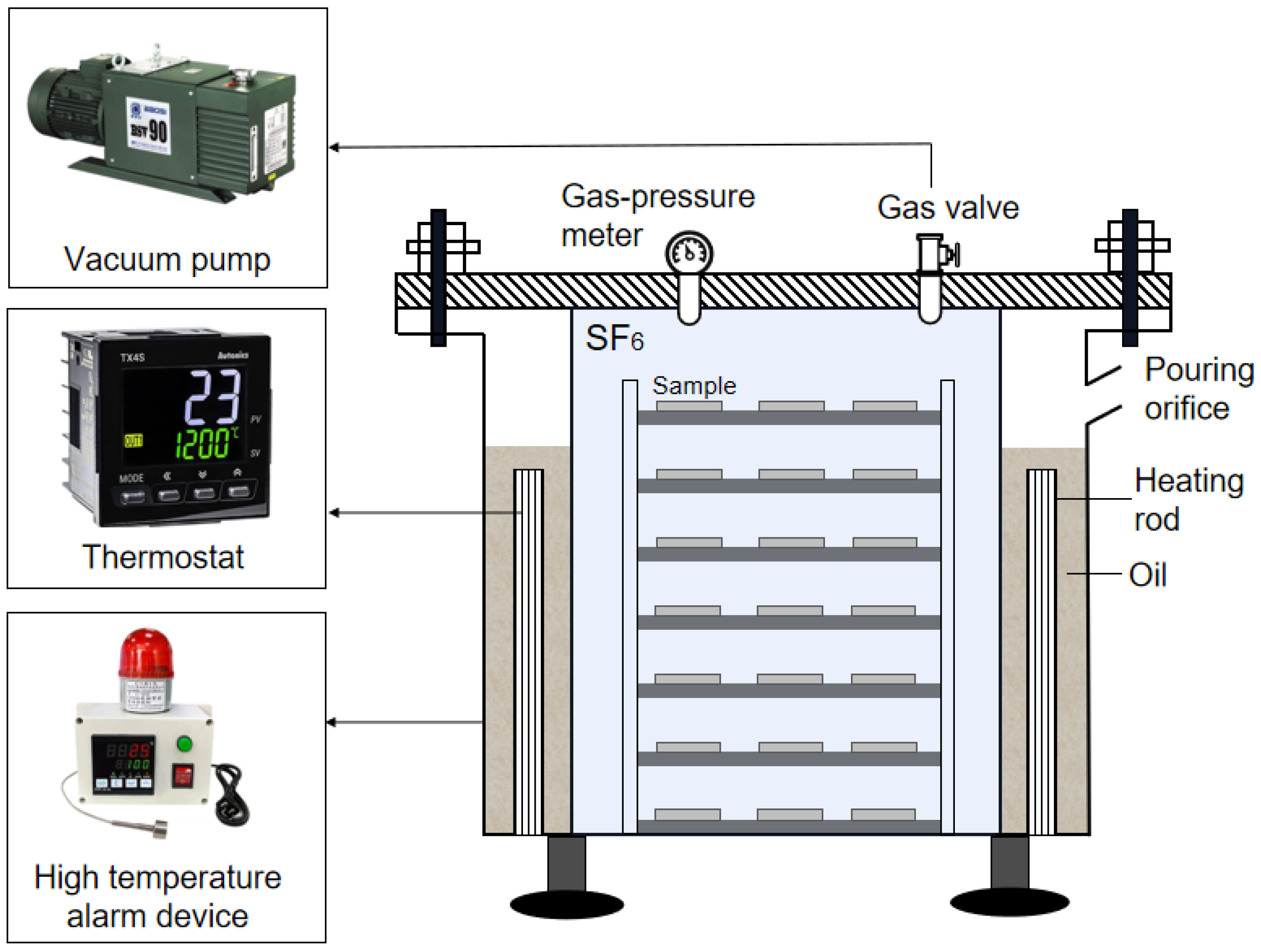
2.2. Ageing Conditions

The occurrence of partial discharge was inhibited by filling SF6 gas in GIL. At high temperature, oxygen in the air has a strong oxidation effect on epoxy resin coating, which would seriously affect the reliability of the experiment. To simulate the actual working conditions in GIL and eliminate the influence of air on the ageing of epoxy coating, the sample was placed in SF6 with an air pressure of 0.1 MPa for thermal ageing. The ageing temperature was set to 160 °C to speed up the experiment and the longest ageing time to 1200 h. The performances of epoxy resin coating were tested at the ageing times of 0 h, 60 h, 180 h, 300 h, 600 h, 900 h and 1200 h. The closed constant temperature heating platform with SF6 is shown in Figure 1. The platform controls the internal temperature by heating the oil with heating rods. The platform is equipped with a temperature control system and a high-temperature alarm device. In each test, a vacuum pump was used to pump the device into the vacuum, and SF6 gas of 0.1 MPa was filled while the change in the barometer was observed. After filling, heating began.
To reduce the error caused by the dispersion of samples, three samples were arranged under each ageing condition for independent repeated tests. At each temperature, the samples were put in reverse order into the closed constant temperature heating platform in SF6, which is shown in Figure 1. The samples with an ageing time of 1200 h were put in first, the samples with an ageing time of 600 h were put in after 600 h, the sample with an ageing time of 300 h was put in after 300 h, and so on. All samples were placed in the ageing chamber according to the required ageing time. The aim was to take all samples out on the same day, effectively avoiding the measurement environment’s impact. After thermal ageing, the samples should be placed in a dry airtight container for at least 24 h before performance testing.

2.3. Measurement

In this article, the change in adhesion between epoxy resin coating and aluminum alloy during the ageing process and the change in inhibitory effect of the coating on the particles after the thermal ageing test were studied, respectively. After the adhesion test of epoxy resin coating, mass loss tests and surface morphology tests were carried out to explain the adhesion change. After that, a lifting experiment was conducted on the surface of the electrode coated with epoxy resin. The adhesion energy, dielectric constant and conductivity were tested to explore the reasons for changing the particles’ lifting voltage and charging time.

2.3.1. Pull-Off Test for Adhesion

The adhesion tester and test principle as shown in Figure 2, the PosiTest AT-A coating adhesion test instrument made by Defelsko was used in the adhesion test. Spindles with a diameter of 20 mm were selected. A two-part Araldite 2015 (Huntsman Advanced Materials, Beijing, China) adhesive was used to stick the spindle to the epoxy coating’s surface. Reference standard ISO-4624-2003 paints and varnishes were used for the pull-off test for adhesion [37]; the pull was applied at a constant rate until the coating fell off. Average coating adhesion was obtained by testing three samples at each ageing time node.

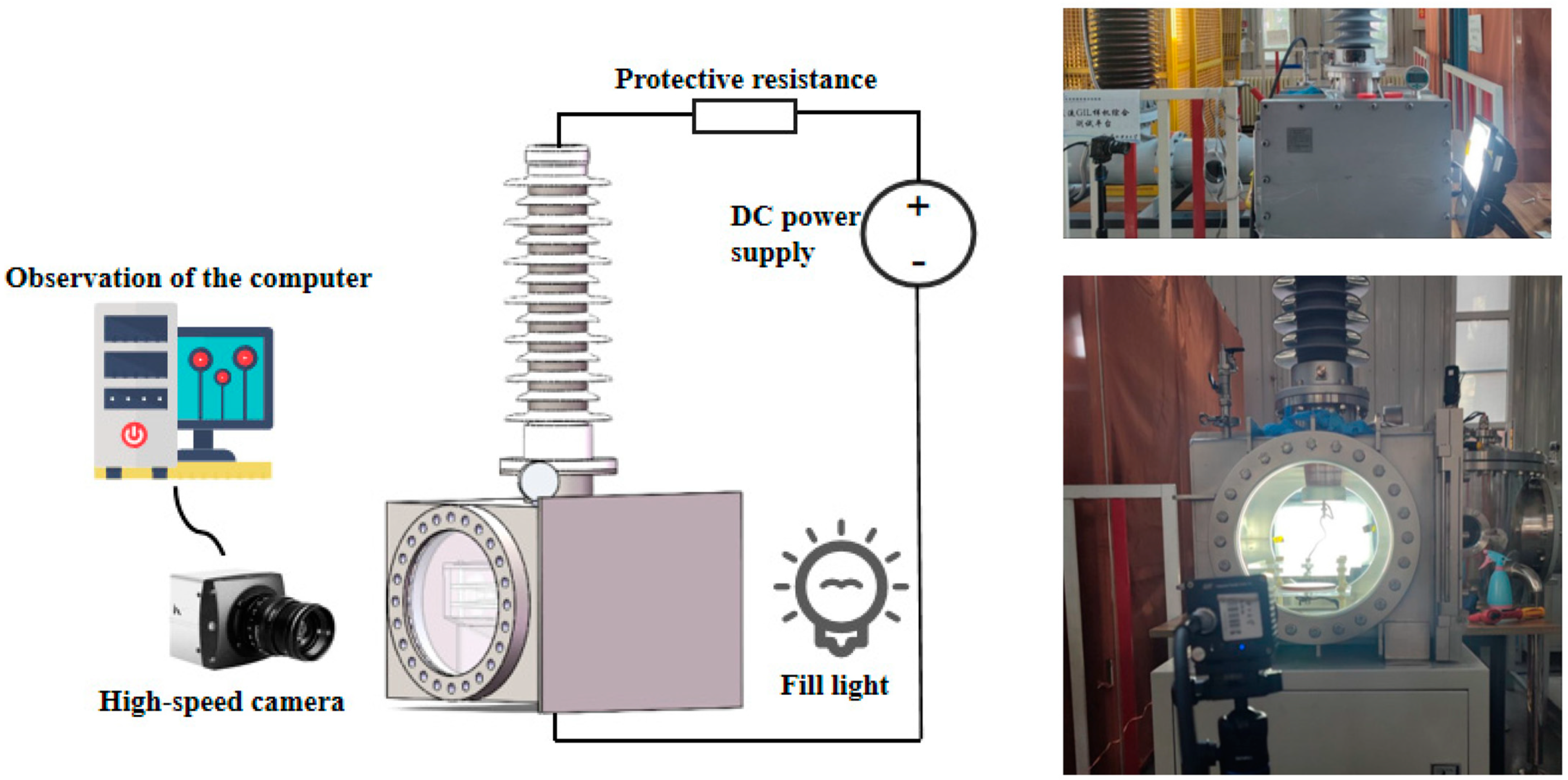
2.3.2. Particle Movement Test

The observation platform of particle motion is shown in Figure 3. The aluminum alloy electrode was suspended with plastic bolts in the funnel-shaped cavity. The pole spacing was set to 20 mm. Then it was placed in a sealed metal cavity, vacuumized and filled with 0.1 MPa SF6 gas so that the breakdown voltage of the experiment could be greater than that of the air environment. The signal generator generated the DC voltage (Agilent 33522A, Palo Alto, CA, USA), amplified 5000 times by the high voltage amplifier (Trek Model 50/12 A, Denver, CO, USA) and applied to the electrode plate. The motion of the metal particles was observed with a high-speed camera (Fastec HiSpec5, Shanghai, China), and the high-speed camera took 1000 frames per second. At the same time, a high-power LED was used to fill the light of the test platform.
The metal particles are aluminum spheres with a radius of 0.3 mm (ρ = 2.7 g/cm3). The electrode surface was coated with epoxy coatings of 50 μm thickness with different ageing times. Before each experiment, the metal particles, electrode plate and epoxy resin coating were wiped with silk soaked with ethanol. After ethanol evaporation, the metal particles were placed on the epoxy resin coating between the electrodes for the particle-lifting experiment.

3. Pull-Off Test for Adhesion

3.1. Experimental Principle

The interfacial adhesion between polymer and metal is an important index to evaluate the performance of coatings. Adhesion represents the maximum load the coating can withstand before separation, and the breaking point is found on the weakest plane consisting of aluminum ingots, glue, coating and substrate. The force is defined as the adhesion between the interfaces when the coating is completely separated from the substrate due to tension [38]. During the adhesion test, the spindle should be perpendicular to the coating. If the spindle is inclined or does not combine well with the adhesive, the stress will be concentrated on the interface between a part of coating and the substrate. Only a small force will destroy the coating, and the measured adhesion is smaller than the actual value. Experimentally measured adhesions include interfacial adhesion, thermal stress, the cohesion of polymer during curing shrinkage and plastic deformation force when it is stripped. Because there is an electric field in GIL, to make the electric field uniform, the interior of the electrode is polished very smoothly. Therefore, 7075 aluminum alloy, as smooth as possible, is selected in the experiment to reduce the mechanical bite between the aluminum alloy and epoxy resin coating.

3.2. Experimental Result

The relationship of adhesion between aluminum and aged epoxy coatings is shown in Figure 4. It can be seen from the figure that the adhesion between the unaged epoxy resin coating and aluminum alloy is 2.628 MPa. After 1200 h of ageing at SF6 at 160 °C, the adhesion decreased to 1.695 MPa, falling by 35.50%. The adhesion is 1.831 MPa at 300 h of ageing, decreasing by 30.32%. The results showed that the decrease in adhesion was mainly concentrated in the early stage of the ageing experiment. During the whole ageing experiment, the adhesion decreased by 0.933 MPa in total. In the first 300 h of ageing, the adhesion decreased by 0.797 MPa, accounting for 85.42% of the decrease in the whole process.
The samples after the adhesion test are shown in Figure 5. Figure 5a–g show the samples with the ageing times of 0, 60, 180, 300, 600, 900 and 1200 h, respectively. As can be seen from the figure, with the extension of ageing time, the surface gloss of the epoxy resin coating gradually decreases, and the coating begins to turn yellow due to heat. The performance of the epoxy resin coating should change significantly during ageing.

3.3. Analysis of Factors Affecting Adhesion Change

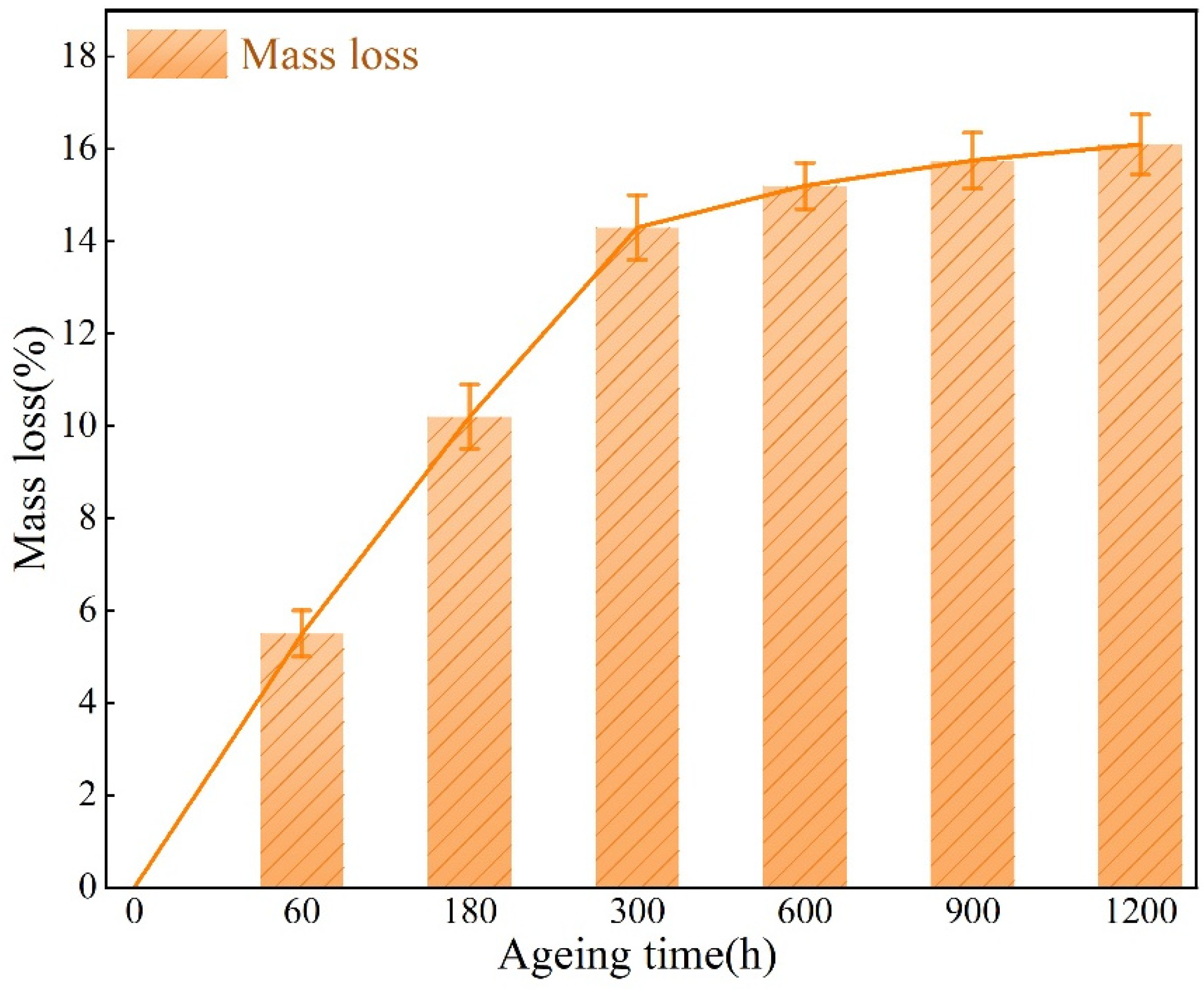
3.3.1. Mass Loss Rate Analysis

A precision balance of 0.01 mg Mettle-Toledo ME104 was used to measure the mass of samples before and after ageing at 160 °C. The mass loss rate is calculated as follows:
η = m 0 m i m 0 × 100 %
where η is the mass loss rate, m 0 is the initial mass of the sample and m i is the mass of the samples at different thermal ageing times.
The Figure 6 shows the relationship between the mass loss rate of epoxy resin coatings and ageing time under the environment of sulfur hexafluoride at 160 °C. With an increase in ageing time, the weight loss rate of epoxy resin coating increases gradually. In the early stage of the ageing test, the coating mass loss rate is the fastest. In the first 300 h, the mass loss rate reaches 14.7%. As the ageing time increases, the mass loss rate decreases and the coating’s quality changes little. After the whole ageing experiment, the mass loss rate reached 16.2%, an increase of only 1.5% compared with the first 300 h. In the first quarter of the ageing experiment, the mass loss accounted for 90.74% of the total mass loss. In the last three quarters of the experiment, the loss rate of quality accounted for only 9.26% of the whole experiment.
In the early stage of ageing, the high temperature makes the crystal water in the epoxy resin coating precipitate rapidly and takes away part of the existing low molecular substances, resulting in a rapid decline in the coating quality. After that, under the action of physical ageing and chemical ageing, the weak bond fracture in the coating produces low molecular substances. The common molecular substances volatilize under continuous high temperatures, making the ageing weight loss rate increase. By the middle and later stage of the ageing experiment, the water of crystallization has been almost lost. The main cause of mass loss is the generation and evaporation of small molecules after decomposition. However, due to high temperature evaporation, the loss rate of small molecules is not as fast as that of crystal water evaporation, so in the middle and later stage of the ageing experiment, the mass loss rate of epoxy coating begins to slow down.

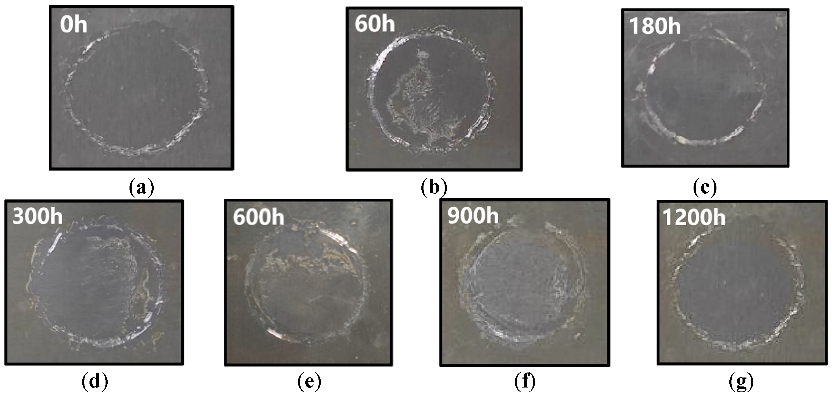
3.3.2. Surface Morphology Analysis

Figure 7 shows the SEM images of samples in different ageing stages at 5000 times magnification. As shown in Figure 7a, the surface of nonaged epoxy resin is flat and smooth, without prominent cracks and bulges, and there are few white spots and texture patterns. As shown in Figure 7b,c, after ageing for 60 h and 180 h, the surface of the samples is no longer flat, and small bulges appear. When the ageing time reaches 300 h, the number of surface protrusions increases and the diameter increases further, and cracks begin to appear simultaneously. With the increase in ageing time, cracks develop where holes appear, and some particles appear on the surface of the epoxy resin coating and become fluffy. When the coating is aged 900 h, the surface defects are further increased. When the coating is aged 1200 h, more and more dense small particle cracks appear on the coating surface. The holes and cracks are further expanded and widened, the structure is fluffy powdery and the surface flatness is significantly damaged.
In the later stage of ageing, many micro-defects can be observed due to the release of internal stress caused by bulge fracture, resulting in coating cracks. The difference in the thermal expansion coefficient between epoxy resin coating and aluminum alloy also results in thermal stress at the interface, which increases the generation of cracks. In addition, long-term thermal radiation will also cause coating cross-linking and shrinkage, further promoting the rupture of the coating, which reduces the protective performance of the coating.

3.4. Discussion

According to the mass loss rate, surface morphology and adhesion changes of epoxy resin coating, in the early experiment, it can be seen that the water of crystallization inside the epoxy resin coating is precipitated, and the volume of the coating shrinks as the quality of the coating decreases. In the process of shrinkage, the interface adhesion is greatly affected. At the same time, due to the precipitation of crystalline water in the epoxy resin coating, the coating is rapidly embrittled, and the mechanical properties are reduced, resulting in a decrease in the tensile capacity of the coating. The coating is more likely to fail in the process of being pulled. In the middle and late stages of the ageing experiment, the chemical bond between the epoxy resin coating and aluminum alloy substrate is broken due to long-term thermal action. Small molecular substances are gradually produced in the coating, and the small molecular substances evaporate under the action of high temperature. The coating also begins to grow bulges and microcracks, which eventually leads to further decline in mechanical properties and further continuous decline in adhesion. The mass loss caused by ageing makes the coating shrink, and because of the evaporation of crystal water and small molecules in the coating, the bumps and cracks in the coating affect the bonding strength between the coating and aluminum alloy, so that the adhesion further continuous decline.

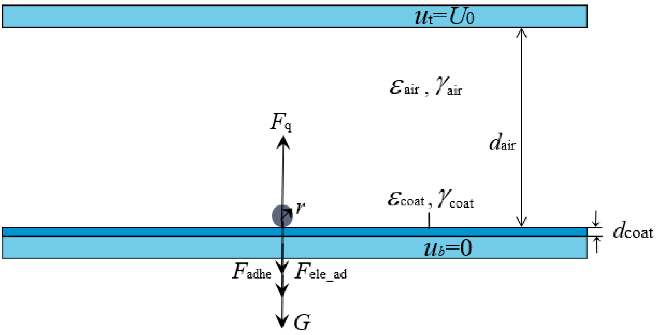
4. Particle-Lifting Experiment

4.1. Experimental Principle

The charging mechanism of metal particles is slightly different in the direct current (DC) field and alternating current (AC) field. When the applied voltage is DC voltage, the particle is charged mainly by conductance current. Under AC voltage, the particles are charged due to micro-discharges between insulating media. The charging and force model of spherical metal particles between plates is shown in Figure 8.
The upper plate is connected to a DC power supply, the voltage is U 0 , the lower plate is grounded and the distance between plates is d air = 20 mm. The epoxy resin coating thickness d coat = 50 μm. The dielectric constant and conductivity of the air gap are ε air and γ air , respectively. The dielectric constant and conductivity of epoxy resin coating are ε coat and γ coat . The radius of spherical particles is r = 0.3 mm. The experiment adopts the method of gradually increasing the voltage. The voltage rise rate is 0.25 kv/s. Wait for 300 s every 5 kV rise, so that the charge can be fully conducted to the particles, and then continue to increase the voltage.
In the vertical direction, the particle itself is subjected to gravity, and there is electrostatic adsorption force and adhesion work between the particle and the coating. When the electrode is coated, the film is polarized by the electric field, and the charge is transferred to the particle to charge the particle. The two processes are synchronous. The polarization time constant and the charge time constant are equal, and their magnitudes are τ :
τ = ε 0 ε coat γ coat
where ε 0 is the dielectric constant of vacuum. When the upper plate voltage U0 is increased, the electrostatic force of the particle F q will increase. When the electrostatic force is greater than the sum of gravity G, electrostatic adsorption force F ele _ ad and adhesion F adhe of the particle, the particle will be lifted.
To study the influence of electrode surface coating on the lifting voltage of particles under DC voltage, the authors built the charging and lifting model of metal particles in previous studies. Considering the electrostatic adsorption force provided by the coating can significantly improve the lifting voltage of the particle, the formula of particle lift voltage at t > 3 τ is calculated experimentally:
U coated - lift = 1.664 ε coat 0.664 ε coat + 1 U bare - lift
where U bare - lift is the particle-lifting voltage at the bare electrode. According to the formula, the larger the dielectric constant of the electrode surface coating, the higher the voltage requirement of the particle to overcome gravity and electrostatic adsorption force, and the higher the lifting voltage. However, the effect of adhesion work between metal particles and epoxy resin coating is not considered in this formula.
Based on this model, Huang Xuwei constructed a formula for lifting the voltage of particles in the coated state considering adhesion work [39]. Concerning metal particle-lifting voltage considering adhesion work under the condition of coating on electrode U lift _ co :
U lift _ co ( t ) = a air 2 ( 1 e t τ ) 1 2 [ ε coat ( ε coat + 1 ) π ε 0 ε air r ] 1 2 [ 4 r 2 ρ g + W a π 180 r arccos ( 1 4 3 r 3 π ρ g k tension ) ] 1 2
where ρ is the density of aluminum particles, g is the acceleration of gravity and k tension is the elastic constant of the epoxy coating. It can be seen from Formula (4) that the starting voltage of metal particles has a positive correlation with the adhesion work W a and the dielectric constant ε coat .

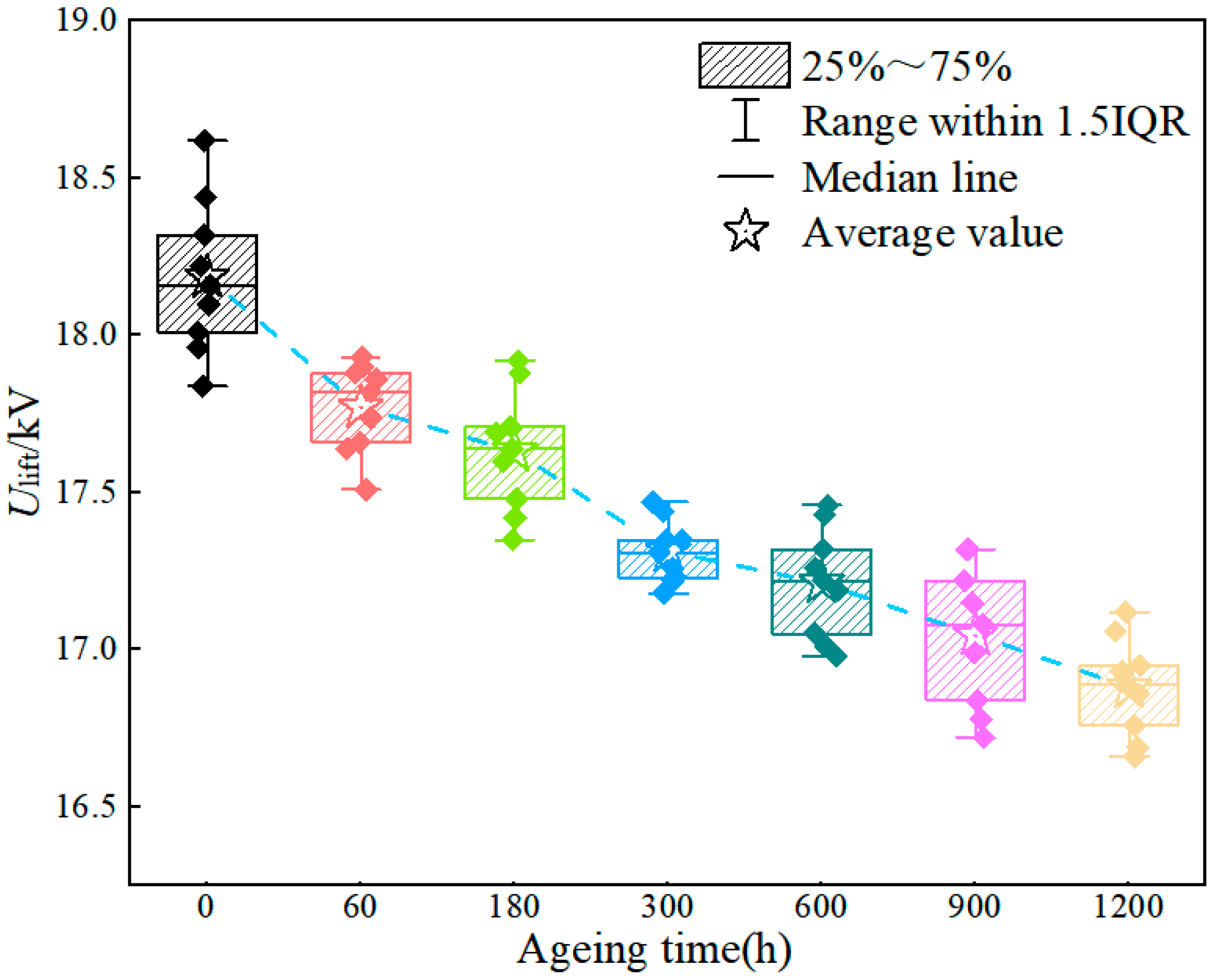
4.2. Experimental Results

The motion photos of aluminum alloy particles between plates are shown in Figure 9. Figure 9a is the picture of the static particle, and Figure 9b is the picture of the lifting particle.
The lifting voltage of particles with different ageing times was tested. The results show that the lifting voltage was 12.42 kV when the test was carried out on the bare electrode. To ensure the reliability of the experimental results, multiple groups of experiments were carried out on samples with different ageing degrees. The experimental results are shown in Figure 10. When the surface of the electrode was coated with epoxy resin, the lifting voltage increased to 18.12 kV, which is about 45.89% higher than that of the bare electrode. With the increase in ageing time, the inhibitory effect of the coating on particles decreased gradually. When the ageing time reached 1200 h, the particle-lifting voltage was about 16.86 kv. Although the lifting voltage decreased, it was still significantly higher than that of the bare electrode, which was about 35.7%, indicating that the ageing coating still had an obvious inhibitory effect on the movement of particles.

4.3. Analysis of Factors Affecting Particle-Lifting Voltage

4.3.1. The Adhesion Work Analysis

There is adhesion between two-phase materials. The adhesion is produced by the mutual adsorption of adhesive and adherend molecules or atoms in the interface layer. Any ideal solid material has cohesive mechanical strength, which depends on the various attractive forces between the basic particles. All the forces that play different roles in the same solid also have adhesive force through interface action when connecting two different materials [40]. The primary condition for these forces to occur at the interface between two substances is that the two substances must be in closest or indirect contact. In GIL, there is contact between aluminum metal particles and coating.
Whether the polarity between the adhesive and the adherend is matched and whether the surface tension is close will affect the firmness of the bonding. Because an interface layer is formed between the two phases, which is different from the bulk phase, the properties of the interface layer greatly influence the mechanical properties of the materials. The bigger the interfacial tension, the lower the adhesion work and the lower the bonding strength. In contrast, the smaller the interfacial tension, the greater the adhesion work and the higher the bonding strength. Because direct measurement of interfacial tension and adhesion work is troublesome and undeveloped, measurement of the contact angle is often used to calculate [41].
The adhesion work was calculated by Young’s equation [36]:
W a = γ ( 1 + cos θ )
where θ is the contact angle, and γ is the surface tension of water. According to Formula (5), the smaller the contact angle, the greater the adhesion work. Good wetting performance can increase the adhesion work of the two phases and thus improve the adhesion strength. The smaller the contact angle θ , the better the wetting property of the material. At the same time, according to the theory of interfacial tension, the wetting capacity of the two phases is stronger when the polarity of the two substances is compatible and the adhesion effect is the largest.
Figure 11 shows the relationship between contact angle and ageing time of epoxy resin coating. The contact angle tested for aluminum is 62.4°. The test results of the contact angle of epoxy resin coating are shown in Figure 8. The contact angle decreases from 103° to 68.7°. The polarity of the aged epoxy resin coating is better matched with that of aluminum, indicating that the adhesion between the aged coating and aluminum alloy is stronger. The increase in adhesion work will make it more difficult for particles to move.

4.3.2. Dielectric Constant and Conductivity Analysis

The dielectric constant at power frequency and conductivity at 30 °C of epoxy resin coatings with different ageing times are tested, and the results are shown in Table 1:
It can be seen from the table that the dielectric constant of the nonaged epoxy resin coating is 5.40. During the ageing process, the dielectric constant shows an apparent downward trend. After 1200 h of ageing, the dielectric constant decreases to 4.10, 24.07%. After the thermal ageing experiment, the charge transfer inside the coating becomes easier. The conductivity increases from 1.34 × 10⁻¹³ S/m to 1.72 × 10⁻¹¹ S/m, which is a significant increase.
In the ageing process, the dielectric constant of epoxy resin coating gradually decreases and the adhesion work gradually increases, which will impact the particle-lifting voltage. If only the influence of the dielectric constant is considered, the particle-lifting voltage should decrease. If only the power of adhesion work is considered, the particle-lifting voltage should increase. According to the experimental results, the particle-lifting voltage still decreases after ageing, indicating that among the indicators affecting the particle-lifting voltage, the change in dielectric constant of the coating is the main influencing factor.
From the changes in conductivity and dielectric constant, it can be seen that with the ageing of the coating, the charging time constant of metal particles will decrease, the charging time will become faster and the inhibition of particle movement will also be weakened.

5. Conclusions

In this paper, the closed constant temperature heating platform and particle motion observation platform in an SF6 atmosphere were built. The pull-off and particle-lifting experiments were carried out for the epoxy resin coating, which was aged for 1200 h in an SF6 atmosphere at 160 °C. This paper reveals the changing rules of coating adhesion reliability and particle inhibition in DC GIL. The results provide guidance for the use and improvement of coatings in practical engineering. The main conclusions are summarized as follows:
(1)
During thermal ageing, the adhesion between epoxy resin and aluminum alloy decreased from 2.628 to 1.695 MPa, a fall of 35.5%. After ageing, the mass of epoxy coating decreased by 16.2%. The mass of epoxy resin coating decreased rapidly in the early stage of ageing, which led to the shrinkage of coating volume and the rapid reduction of adhesion. The generation of microcracks will further reduce the adhesion.
(2)
When the electrode surface was coated with epoxy coating, the lifting voltage of the particle increased by 45.89% compared with that of the bare electrode. After ageing, the inhibition effect on particles was weakened, but the lifting voltage of particles still increased by 35.7%. Obviously, the aged coating still has a significant inhibitory effect on particles. The dielectric constant of the coating decreased by 24.07% due to ageing, which is the main reason for the weakened inhibition of the coating on particles.
(3)
In the ageing process, the adhesion work between particles and the coating increased, the dielectric constant of the coating itself decreased and the starting voltage decreased, which proves that the change in the dielectric constant of the coating has a greater impact on the lifting voltage of particles than the adhesion work.

Author Contributions

Conceptualization, J.W. and Z.W.; methodology, J.W. and Z.W.; software, J.W. and R.L.; validation, J.W. and R.X.; formal analysis, Q.L.; investigation, J.W.; data curation, Z.W.; writing—original draft preparation, J.W.; writing—review and editing, J.W.; supervision, Q.L.; project administration, J.W.; funding acquisition, J.W. All authors have read and agreed to the published version of the manuscript.

Funding

This research was funded by the National Natural Science Foundation of China (52177140), and the Fundamental Research Funds for the Central Universities (2022JG003).

Institutional Review Board Statement

Not applicable.

Informed Consent Statement

Not applicable.

Data Availability Statement

All data included in this study are available upon request by contact with the corresponding author.

Conflicts of Interest

The authors declare no conflict of interest.

References

  1. Xiao, D.; Yan, J. Application and development of gas insulated transmission line (GIL). High Volt. Eng. 2017, 43, 699–707. [Google Scholar]
  2. Koch, H.; Hopkins, M. Overview of Gas Insulated Lines; IEEE: San Francisco, CA, USA, 2005; pp. 940–944. [Google Scholar]
  3. Koch, H. Basic Information on Gas Insulated Transmission Lines(GIL); IEEE: Pittsburgh, PA, USA, 2008; pp. 1–4. [Google Scholar]
  4. Tang, H.; Wu, G.; Fan, J. Insulation design of gas insulated HVDC transmission line. Power Syst. Technol. 2008, 32, 65–70. [Google Scholar]
  5. Magier, T.; Tenzer, M.; Koch, H. Direct current gas insulated transmission lines. IEEE Trans. Power Deliv. 2018, 33, 440–446. [Google Scholar] [CrossRef]
  6. Straumann, U.; Schuller, M.; Franck, C.M. Theoretical Investigation of HVDC Disc Spacer Charging in SF6 Gas insulated Systems. IEEE Trans. Dielectr. Electr. Insul. 2013, 19, 2196–2205. [Google Scholar] [CrossRef]
  7. Mansour, D.; Nishizawa, K.; Kojima, H. Charge accumulation effects on time transition of partial discharge activity at GIS spacer defects. IEEE Trans. Dielectr. Electr. Insul. 2010, 17, 247–255. [Google Scholar] [CrossRef]
  8. Kindersberger, J.; Lederle, C. Surface charge decay on insulators in air and sulfurhexafluorid—Part I: Simulation. IEEE Trans. Dielectr. Electr. Insul. 2008, 15, 941–948. [Google Scholar] [CrossRef]
  9. Kindersberger, J.; Lederle, C. Surface charge decay on insulators in air and sulfurhexafluorid—Part II: Measurements. IEEE Trans. Dielectr. Electr. Insul. 2008, 15, 949–957. [Google Scholar] [CrossRef]
  10. Li, C.; Hu, J.; Lin, C. Surface charge migration and dc surface flashover of surface-modified epoxy-based insulators. J. Phys. D Appl. Phys. 2017, 50, 065301. [Google Scholar] [CrossRef]
  11. Hama, H.; Hikosaka, T.; Okabe, S. Cross-equipment study on charging phenomena of solid insulators in high voltage equipment. IEEE Trans. Dielectr. Electr. Insul. 2007, 14, 508–519. [Google Scholar] [CrossRef]
  12. Zhang, C.; Uin, H.; Zhang, S. Plasma surface treatment to improve surface charge accumulation and dssipation of epoxy resin exposed to DC and nanosecond-pulse voltages. J. Phys. D Appl. Phys. 2017, 50, 5203–5214. [Google Scholar]
  13. Kochh, C. Turbulent Natural Convection and Thermal Behavior of Cylindrical Gas Insulated Transmission Lines(GIL); IEEE: Washington, DC, USA, 2001; pp. 162–166. [Google Scholar]
  14. Hillers, T. Gas Insulated Transmission Lines (GIL): Ready for the Real World; IEEE: Singapore, 2000; pp. 575–579. [Google Scholar]
  15. Zhang, Z.; Zhang, Z.; Deng, B. Research Status and Prospect of Surface Charge on DC GIL Insulator. Insul. Mater. 2019, 52, 1–7. [Google Scholar]
  16. Li, J.; Liu, M.; Niu, G.; Xiong, Q.; Ma, Y.; An, R.; Bai, W.; Qin, C.; Ren, W. Enhanced Anti-Corrosion Performances of Epoxy Resin Using the Addition of Sodium Dodecylbenzene Sulfonate-Modified Graphene. Coatings 2021, 11, 655. [Google Scholar] [CrossRef]
  17. Hussian Siyal, S.; Ali Jogi, S.; Muhammadi, S.; Ahmed Laghari, Z.; Ali Khichi, S.; Naseem, K.; Saad Algarni, T.; Alothman, A.; Hussain, S.; Javed, M.S. Mechanical Characteristics and Adhesion of Glass-Kevlar Hybrid Composites by Applying Different Ratios of Epoxy in Lamination. Coatings 2021, 11, 94. [Google Scholar] [CrossRef]
  18. Abakah, R.R.; Huang, F.; Hu, Q.; Wang, Y.; Liu, J. Comparative Study of Corrosion Properties of Different Graphene Nanoplate/Epoxy Composite Coatings for Enhanced Surface Barrier Protection. Coatings 2021, 11, 285. [Google Scholar] [CrossRef]
  19. Yang, S.; Huo, S.; Wang, J.; Zhang, B.; Wang, J.; Ran, S.; Fang, Z.; Song, P.; Wang, H. A highly fire-safe and smoke-suppressive single-component epoxy resin with switchable curing temperature and rapid curing rate. Compos. Part B-Eng. 2021, 207, 108601.1–108601.11. [Google Scholar] [CrossRef]
  20. Aslan, A.; Salur, E.; Düzcükolu, H. The effects of harsh aging environments on the properties of neat and MWCNT reinforced epoxy resins. Constr. Build. Mater. 2021, 22, 121929. [Google Scholar] [CrossRef]
  21. Parekh, H.; Srivastava, K.D.; van Heeswijk, R.G. Lifting field of free conducting particles in compressed SF6 with dielectric coated electrodes. IEEE Trans. Power Appar. Syst. 1979, PAS-98, 748–758. [Google Scholar] [CrossRef]
  22. Srivastava, K.D.; van Heeswijk, R.G. Dielectric coatingseffect on breakdown and particle movement in GITL systems. IEEE Trans. Power Appar. Syst. 1985, PAS-104, 22–31. [Google Scholar] [CrossRef]
  23. Hama, H.; Okabe, S. Factors dominating dielectric performance of real-size gas insulated system and their measures by dielectric coatings in SF6 and potential gases. IEEE Trans. Dielectr. Electr. Insul. 2013, 20, 1737–1748. [Google Scholar] [CrossRef]
  24. Kim, S.; Hong, H.; Han, T.H.; Kim, M.O. Early-Age Tensile Bond Characteristics of Epoxy Coatings for Underwater Applications. Coatings 2019, 9, 757. [Google Scholar] [CrossRef] [Green Version]
  25. Kim, S.; Hong, H.; Park, J.K.; Park, S.; Choi, S.I.; Kim, M.O. Effect of Exposure Conditions on the Interfacial Bond Properties of SS400 Plate Coated with Various Epoxy Resins. Coatings 2020, 10, 1159. [Google Scholar] [CrossRef]
  26. Zhang, T.; Zhang, T.; He, Y.; Zhang, S.; Ma, B.; Gao, Z. Long-Term Atmospheric Aging and Corrosion of Epoxy Primer-Coated Aluminum Alloy in Coastal Environments. Coatings 2021, 11, 237. [Google Scholar] [CrossRef]
  27. Kurdi, J.; Ardelean, H.; Marcus, P. Adhesion properties of aluminium-metallized/ammonia plasma-treated polypropylene: Spectroscopic analysis (XPS, EXES) of the aluminium/polypropylene interface. Appl. Surf. Sci. 2002, 189, 119–128. [Google Scholar] [CrossRef]
  28. Chiang, P.C.; Whang, W.T.; Wu, S.C. Effects of titania content and plasma treatment on the interfacial adhesion mechanism of nano titania -hybridized polyimide and copper system. Polymer 2004, 45, 4465–4472. [Google Scholar] [CrossRef]
  29. Kondoh, E. Material characterization of Cu(Ti) polyimide thin film stacks. Thin Solid Films 2000, 359, 255–260. [Google Scholar] [CrossRef]
  30. Fuseini, M.; Zaghloul, M.M.Y.; Elkady, M.F.; El-Shazly, A.H. Ebaluation of synthesized Polynailine nanofibres as corrosion protection film coating on copper substrate by electrophoretic deposition. J. Mater. Sci. 2022, 57, 6085–6101. [Google Scholar] [CrossRef]
  31. Zaghloul, M.M.Y.; Mohamed, Y.S.; El-Gamal, H. Fatigue and tensile behaviors of fiber-reinforced themosetting composites embedded with nanoparticles. J. Compos. Mater. 2019, 53, 709–718. [Google Scholar] [CrossRef]
  32. Zaghloul, M.M.Y.; Steel, K.; Veidt, M.; Heitzmann, M.T. Wear behavior of polymeric materials reinforced with man-made fibres: A Comprehensive review about fibre volume fraction influence on wear performance. J. Reinf. Plast. Compos. 2021, 41, 215–241. [Google Scholar] [CrossRef]
  33. Zaghloul, M.M.Y. Machanical properties of linear low-denisity polyethylene fire-retarded with melamine polyphosphate. J. Appl. Polym. Sci. 2018, 135, 46. [Google Scholar] [CrossRef]
  34. Xie, W.; Yang, Z.; Cheng, X. Study on Thermo-Oxygen Aging Characteristics of Epoxy Resin Material. Diangong Jishu Xuebao 2020, 35, 4397–4404. [Google Scholar]
  35. Li, Q.; Liu, W.; Han, S.; Lu, X. Analysis on Partial Discharge Characteristics of Epoxy Resin Insulation During High-frequency Electrical-thermal Aging. High Volt. Eng. 2015, 41, 389–395. [Google Scholar]
  36. Wang, Y.; Liu, Y.; Wang, S.; Xu, H. The Effect of Electrothermal Aging on the Properties of Epoxy Resin in Dry-Type Transformer. Diangong Jishu Xuebao 2018, 33, 3906–3916. [Google Scholar]
  37. EN ISO 4624-2003; Paints and Varnishes—Pull-Off Test for Adhesion. ISO: Geneva, Switzerland, 2003.
  38. Dmitruk, A.; Mayer, P.; Pach, J. Pull-off strength and abrasion resistance of anti-corrosive polymer and composite coatings. Int. J. Surf. Sci. Eng. 2019, 13, 50. [Google Scholar] [CrossRef]
  39. Huang, X.; Ni, X.; Wang, J.; Li, Q.; Lin, J.; Wang, Z. Synthesis of Phenyl-Thioether Polyimide as the Electrode Coating Film and Its Suppression Effect on Motion Behavior of the Metal Particles under DC Stresses. Diangong Jishu Xuebao 2018, 33, 4712–4721. [Google Scholar]
  40. Li, D.; Neumann, A.W. A reformulation of the equation of state for interfacial tensions. J. Colloid Interface Sci. 1990, 137, 304–307. [Google Scholar] [CrossRef]
  41. Sun, J.; Nie, F.; Zhang, L. The calculation of interfacial tension and adhesive work for TATB to fluoropolymer. Adhension 2001, 22, 27–28. [Google Scholar]
Figure 1. Closed constant temperature heating platform in SF6.
Coatings 12 00858 g001
Figure 2. PosiTest AT-A coating adhesion test instrument and test principle.
Coatings 12 00858 g002
Figure 3. Particle motion observation platform.
Coatings 12 00858 g003
Figure 4. Relationship of adhesion between aluminum and aged epoxy coatings.
Coatings 12 00858 g004
Figure 5. Samples after the pull-off test. (a) 0 h; (b) 60 h; (c) 180 h; (d) 300 h; (e) 600 h; (f) 900 h; (g) 1200 h.
Coatings 12 00858 g005
Figure 6. The relationship of mass loss rate of aged epoxy coatings with time.
Coatings 12 00858 g006
Figure 7. The SEM images of samples in different ageing stages at 5000 times magnification. (a) 0 h; (b) 60 h; (c) 180 h; (d) 300 h; (e) 600 h; (f) 900 h; (g) 1200 h.
Coatings 12 00858 g007
Figure 8. Charging and force model of spherical metal particles.
Coatings 12 00858 g008
Figure 9. (a) The picture of the static particle (b) The picture of the lifting particle.
Coatings 12 00858 g009
Figure 10. Lifting voltage of epoxy resin coating under different ageing time.
Coatings 12 00858 g010
Figure 11. Relationship between contact angle and ageing time of epoxy resin coating.
Coatings 12 00858 g011
Table 1. Dielectric constant and conductivity of epoxy resin coating under different ageing time.
Ageing Time (h)0601803006009001200
Dielectric constant (F/m)5.405.124.814.624.374.254.10
Conductivity (S/m)1.34 × 10−133.34 × 10−136.16 × 10−131.84 × 10−124.12 × 10−128.57 × 10−121.72 × 10⁻¹¹
Publisher’s Note: MDPI stays neutral with regard to jurisdictional claims in published maps and institutional affiliations.

