Article

Effect of Si Content on Deposition and High-Temperature Oxidation of Al-Si Coatings Obtained by Magnetron Sputtering PVD Method

1
German Aerospace Center (DLR), Institute of Materials Research, Linder Hoehe, 51147 Cologne, Germany
2
Łukasiewicz Research Network-Institute for Ferrous Metallurgy, 44-100 Gliwice, Poland
*
Author to whom correspondence should be addressed.
Submission received: 16 May 2022 / Revised: 10 June 2022 / Accepted: 14 June 2022 / Published: 18 June 2022

Abstract

:
Intermetallic Al-Si-based coatings can greatly increase the oxidation resistance of γ-TiAl alloys. However, the effects of the Si addition are not fully understood. Therefore, it is difficult to determine the Si content that is optimal for oxidation resistance. Therefore, pure Al and several Al-Si coatings with varying Si contents between 1 and 81 at.% were studied. The coatings were produced using a combinatorial magnetron sputtering process. Scanning electron microscopy and energy dispersive X-ray spectroscopy were used for structure and chemical analysis. The phases were identified by X-ray diffraction. Cyclic oxidation tests at 900 °C were conducted up to 5000 cycles of 1 h each and subsequently evaluated by thermogravimetric analysis. Si addition in the range of 1 to 12 at.% did not deteriorate the oxidation resistance compared to a pure Al coating up for 1000 cycles (1 h) of oxidation at 900 °C, while higher Si contents led to a high mass gain. For oxidation times up to 5000 cycles (1 h), a sufficient thickness of the coatings is crucial for good oxidation resistance. The main effect of Si addition is to enhance the transformation speed of the deposited Al and Si to the high temperature stable Ti(Al,Si)3 phase during the heat treatment. Si additions of up to 12 at.% led to increased initial mass gains and a decrease in the oxidation rates during subsequent exposures compared to pure Al coatings.

1. Introduction

Titanium aluminides (γ-TiAl) are suitable high-temperature structural materials due to their low density, high strength and good oxidation resistance [1,2,3]. However, the application temperature of γ-TiAl is limited to a maximum of around 750–800 °C due to their inherently low oxidation resistance [4,5,6,7,8]. Coatings are one feasible way to increase the oxidation resistance so that operation temperatures above 800 °C can be achieved [9,10].
The literature indicates that decent oxidation resistance is obtained with various coatings prepared using simple aluminizing of TiAl [10,11,12,13,14,15,16,17,18,19]. The oxidation resistance based on the formation of the oxidation-resistant TiAl3 phase leads to a protective, thermally grown Al2O3 layer [10,11,12]. A further increase in oxidation resistance can be achieved by modification of the aluminizing coatings with silicon [13,14,15,16,17,18,19]. Several reasons for the positive effect of Si on the oxidation behavior of pure Ti as well as Ti and TiAl alloys are proposed in the literature. Different authors stated the formation of SiO2 as the reason for an improved oxidation resistance since it possesses a low oxygen diffusivity and is therefore known as a slow-growing protective oxide [20,21,22]. Additionally, SiO2 particles in TiO2 lead to a densification with only minor grain growth of TiO2 and thus increase the adhesion of the thermally grown oxide layer [23,24,25]. The presence of Si in TiO2 as a solid solution reduces the oxygen diffusion through the oxide scale by blocking the interstitial positions [22,23]. Vojtěch et al. [22] stated that Si can promote the formation of a protective titanium nitride layer below the thermally grown oxide layer on a Ti-7.8Si (in wt.%) alloy, which reduces the oxidation rate in the temperature range of 750 to 1050 °C. However, the formation of a titanium nitride layer is only beneficial for binary Ti-Si alloys. For γ-TiAl alloys, the formation of a titanium nitride layer would be detrimental due to the “nitrogen effect”, which promotes the formation of a non-protective TiO2 layer rather than protective Al2O3 [5,26]. Therefore, the suppression of a nitride formation in Ti-Al-Si systems could also be one important effect arising from Si-based coatings on γ-TiAl alloys, as indicated by Moskal et al. [27].
Novák et al. [28] attributed the positive effect of Si to the formation of a continuous Ti5Si3 sublayer below the thermally grown oxide scale of TiO2 and Al2O3 on a Ti-15Al-15Si (in wt.%) alloy. However, the intermetallic Ti5Si3 phase can also lead to growth of a SiO2 layer with high oxidation resistance [29,30].
In the presence of Al, the Ti5Si3 phase can have a positive impact on the oxidation resistance of Al-rich coatings: in several studies, the formation of Ti5Si3 in Al-Si-based coatings on γ-TiAl alloys was observed [31,32,33]. Segregation of the Ti5Si3 phase at the grain boundaries of the TiAl2 and TiAl3 phases embedded in an Al-rich matrix of Al-Si-based coatings can act as an Al diffusion barrier [34]. Moreover, the inhibited Al diffusion due to the Ti5Si3 phase can counteract the Al depletion in Al-rich Ti-Al coatings [32,33,34].
Further effects are being discussed to arise from Si that is dissolved in the TiAl3 phase. Previous thermodynamic calculations showed that the formation of Ti5Si3 from the Ti(Al,Si)3 phase helps with decelerating the transformation of the protective TiAl3 to TiAl2 and eventually to a non-protective TiAl. This is due to the fact that Ti is “gettered” by the formation of Ti5Si3 when Al is consumed into the Al2O3 growth [32,33] and thus also suppresses the formation of non-protective TiO2. However, the formation of the Ti5Si3 phase in Al-Si coatings on TiAl alloys can also have a detrimental effect: prior to the formation of stable and slow-growing α-Al2O3, the development of a metastable and fast-growing θ-Al2O3 was already reported during the initial oxidation processes of TiAl3 at 900 °C by Gauthier et al. [12]. Therefore, the stabilization of the TiAl3 phase by additions of Si leads to an enhanced formation of the fast-growing θ-Al2O3. This results in a higher mass gain during the initial oxidation for the Si-richer aluminide coating on γ-TiAl substrate alloys, as shown by Swadźba et al. [17].
In summary, there is no clear conclusion on the mechanisms and extent that the addition of Si to Al-based oxidation protective coatings on γ-TiAl alloys improves their oxidation resistance. Thus, systematic studies are required to find the optimal range for the best oxidation protection of Al-Si-based coatings. Only a few of these studies have been published so far: a systematic study of Al-Si coatings on γ-TiAl with Si contents between 0 and 100% in the slurry was performed by Moskal et al. [27]. They found that Si contents of 5 and 12.5 at.% Si in the slurry led to the most beneficial oxidation behavior after 500 h of oxidation at 900 °C. In the study by Swadźba et al. [17], a low Si content had the lowest mass gain after 130 cycles of 23 h at 850 °C. These authors also compared a pure aluminide coating with “high-Si” and “low-Si” containing Si-aluminide coatings produced by pack cementation (90 and 80 wt.% Si in the pack) [17].
Further systematic studies are necessary to obtain a more profound understanding of the involved effects of Si on phase development during oxidation and the oxidation behavior of Al-Si-based coatings for γ-TiAl alloys. The current work focuses on this topic in order to provide a fundamental explanation of these effects of Si as well as help to develop a more effective Al-Si-based oxidation-resistant coating with a precise composition. Therefore, a pure aluminide coating and several Al-Si coatings with different Si contents from 1 to 81 at.% were deposited on TNB-V2, a third-generation γ-TiAl alloy, using magnetron sputtering. The coatings were tested up to 5000 cycles (of 1 h) under cyclic oxidation at 900 °C. The magnetron sputtering allowed the combinatorial deposition of several compositions in one coating batch.

2. Material and Methods

2.1. Substrate Material

The γ-TiAl alloy TNB-V2 (nominal chemical composition listed in Table 1) was used as substrate material. The material was purchased from GfE Gesellschaft für Elektrometallurgie and machined by electrical discharge machining (EDM) to flat coin samples. The samples had a thickness of 1 mm and a diameter of 15 mm as well as a 2 mm borehole for fixation during the coating deposition process and the cyclic oxidation test. Prior to coating deposition, the samples were vibratory polished to a surface roughness below Sa = 1.6 µm and ultrasonically cleaned in ethanol.

2.2. Coating Deposition by Combinatorial DC Magnetron Sputtering

The different intermetallic-based Al-Si and the pure Al coatings were deposited by magnetron sputtering using an IMPAX 100 HT system from SVS Vacuum Coating Technology. A combinatorial approach was used for the deposition of the different Al-Si coatings. The TiAl samples were fixed on 8 different positions between the two pure elemental targets of Al and Si. Due to the different distances between the targets and the samples, varying chemical coating compositions were achieved in one batch process. The received chemical compositions of the different Al-Si-based coatings on the TNB-V2 alloy are summarized in Table 2. The pure Al coating was deposited in a separate sputtering process by placing the samples directly in front of the Al source. All deposition processes were performed at a substrate temperature of 200 °C in order to reduce thermal stress in the coatings during deposition.
Two coating runs with different setups of pylons were carried out (Figure 1). Different positions in the overlapping Al and Si plasmas allowed different chemical compositions. The samples at the positions 2, 4 and 5 were fixed at different heights, which allowed shadowing of one of the plasmas partially. Closer distances of the sample to a target increased the concentration of the corresponding element in the final coating. At position 3, the geometric distances from the sample to the Al and the Si targets were identical.
Different power was used for the Al target (3 kw) and Si target (1.2 kW) in order to reproduce the Al-18Si paper (in at.%) of a previous work [32] at position 3. However, due to shadowing effects of the additional pylons on positions 1 and 5, the Si content was only 12 at.%. In this work, two runs in total were conducted to produce the 8 compositions (1st run: Figure 1a; 2nd run: Figure 1b). Between Al-12Si and Al-58Si, a larger gap of compositions occurred, which was due to the sample positioning and shadowing.
The pylons as well as the samples themselves rotated in order to obtain a homogeneous coating around the specimens. The pressure during the process was 5.1 × 10⁻³ mbar, which resulted from an argon flow of 300 sccm. The total deposition time was 4 h. After the deposition, all coatings were annealed in a high-vacuum furnace with a pressure below 10−5 mbar at 600 °C for 20 h using a heating rate of 0.5 K/min followed by a shutdown of the furnace.

2.3. Cyclic Oxidation Tests at 900 °C in Lab Air

Cyclic oxidation tests were carried out in an automatic test rig at a calibrated temperature of 900 °C in laboratory air. Each cycle consisted of 60 min of heating followed by 10 min of air cooling. The mass changes were measured with an ME5-OCE balance from Sartorius after different numbers of cycles.
The parabolic growth constant was calculated from a Δm vs. t1/2 plot where Δm is the mass change and t the time of oxidation. The initial mass gain Δmi was determined as the intercept from the regression line for parabolic growth in the Δm vs. t1/2 plot. This calculation is valid for the assumption that the growth follows a parabolic course starting at t = 0. A detailed description of this method was published by Pieraggi [35]. However, the obtained results are only an estimation since cyclic oxidation tests were used. For more precise results, isothermal oxidation tests would be required since the handling of the oxidized samples during the weighing process influences the results. However, cyclic testing involves the stresses generated by each cycle and represent a more realistic testing condition for a potential application in aeroengines.

2.4. Analytic Methods

Cross-sectional microanalysis of the coating microstructures and chemical compositions was conducted by scanning electron microscopy (SEM) using an FEI Helios NanoLab 600i equipped with UltraDry energy-dispersive X-ray spectroscopy (EDS) from Thermo Fisher Scientific. All the SEM images are backscatter electron images using a circular backscatter detector. For the phase identification, X-ray diffraction measurements were performed utilizing a Bruker D8 advanced diffractometer, equipped with a Cu tube, using Bragg–Brentano geometry.

3. Results

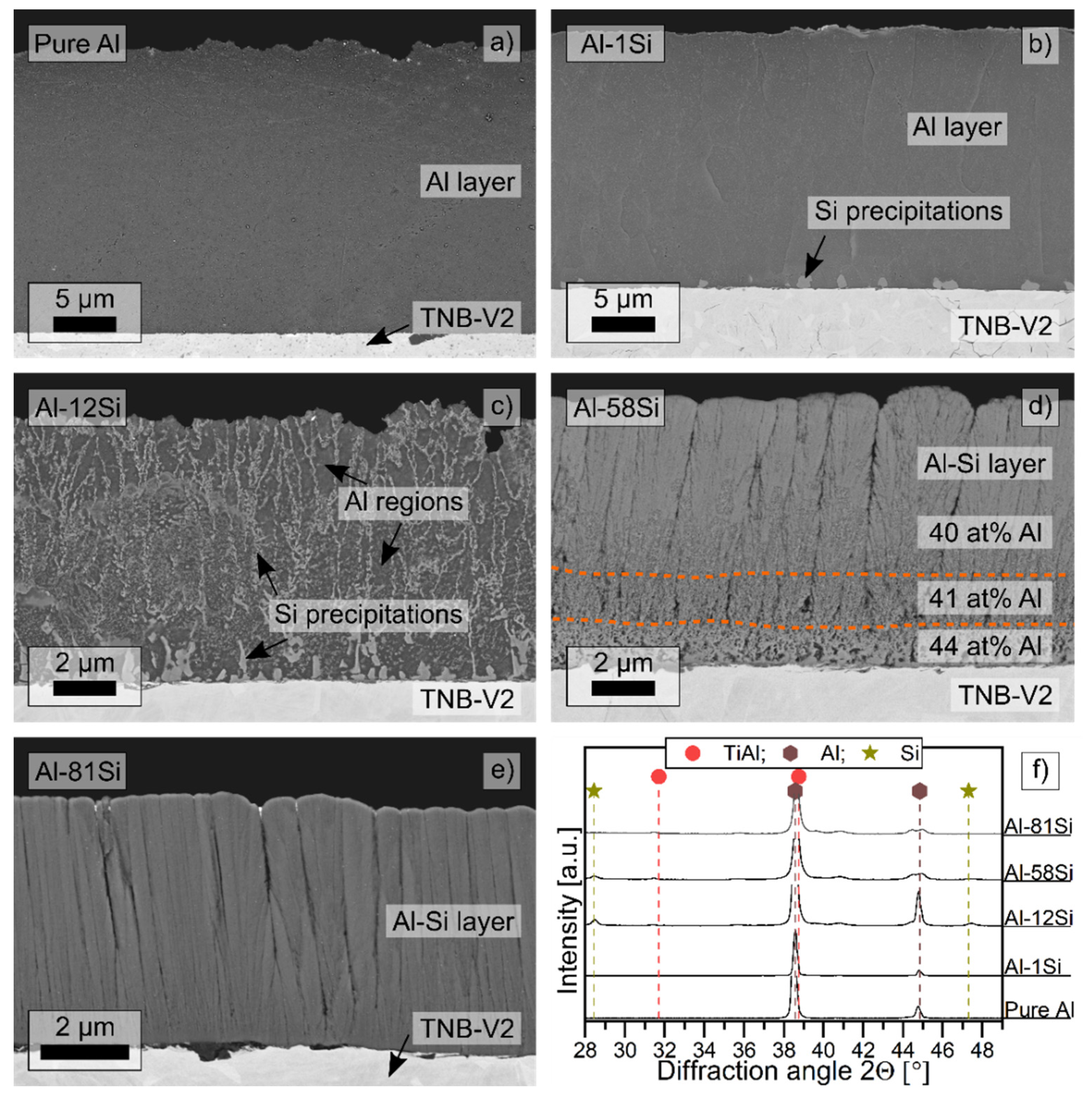
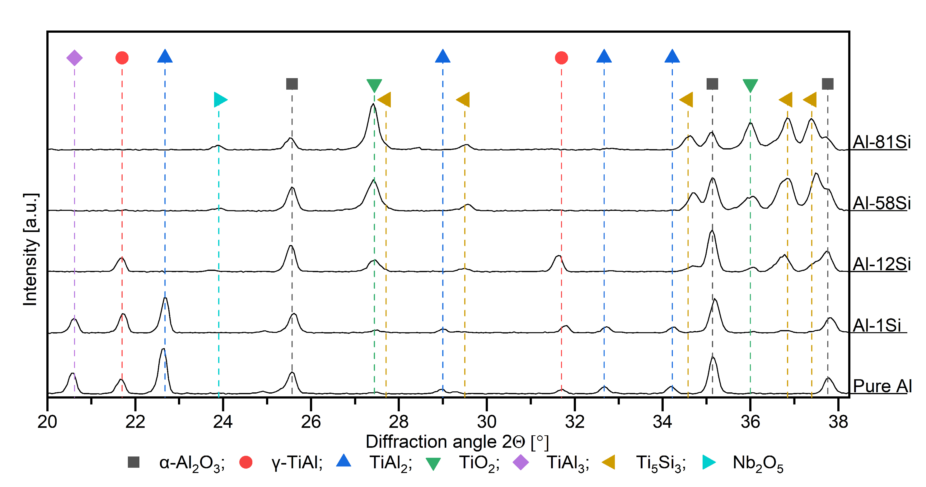
3.1. Intermetallic Al-Si-Based and Pure Al Coatings in the As-Coated Condition and after Vacuum Heat Treatment for 20 h at 600 °C

The respective microstructures of the deposited coatings of pure Al, Al-1Si, Al-12Si, Al-58Si and Al-81Si (at.%) on the γ-TiAl-based alloy TNB-V2 are shown in the SEM cross sections in Figure 2a–e. Additionally, the corresponding XRD results are displayed in Figure 2f. These coating compositions were chosen because they cover the whole range of different morphologies received after deposition by DC magnetron sputtering. The coating morphologies of the Al-2Si and Al-3Si coatings are comparable to the Al-1Si coating, whereas the Al-64Si coating is comparable to the Al-58Si, and the Al-78Si is similar to the Al-81Si coating (at.%).
The microstructure of the deposited layers changed as a consequence of the increasing amount of Si. The pure Al coating shows a dense and homogeneous morphology (Figure 2a). The Al-1Si coating has a very similar microstructure as the pure Al coating: it is dense and homogenous (Figure 2b). Unlike the pure Al coating, few round Si grains are present close to the coating/substrate interface, but no Si was detected by EDS in the Al phase. The Al-12Si coating shows a two-phase, branched morphology in most regions of the coating and more globular grains only at the coating/substrate interface (Figure 2c). The Si grains are embedded in a dense Al matrix without any voids, comparable to the Al-18Si coating from previous work [32].
The Al-58Si coating provides a columnar morphology consisting of Si columns with Al located in the intercolumnar gaps (Figure 2d). The columnar structure can be subdivided into three different layers showing a different coating density as well as different Al contents. At the substrate/coating interface, several Si branches are visible. However, the structure is more like a random network including larger pores. The Al content in this region is 44 at.% (balance: Si). The layer on top of that is indicated by fewer Si branches and gaps that have grown together. The Al content decreases to 41 at.%. In the upper layer, the Si branches have grown together densely, and only small gaps are visible. The latter morphology is predominant in most of the coating and is characterized by a homogeneous growth and an Al content of 40 at.%.
The Al-81Si coating provides an amorphous, columnar morphology of Si supersaturated with Al and Al in the columnar gaps (Figure 2e). Some darker regions are visible between the coating and substrates. These are residues from EDM, which were not removed by vibratory finishing. However, all coatings provide a good adhesion to the TNB-V2 substrate.
Except the Al-81Si coating, all coatings are, at least partially, crystalline. Peaks of pure Al are present in all crystalline coatings (Figure 2f). In the Al-81Si coating, the Si emerges as an amorphous phase; thus, no Si reflexes are visible. The Si reflex in the Al-58Si coating is broadened and not as sharp as in the Al-12Si coating, indicating amorphous regions in the Si phase.
After the magnetron sputtering deposition, the Al-Si coatings were heat treated at 600 °C for 20 h in a vacuum in order to form intermetallic Ti-Al and Ti-Si phases. SEM micrographs and XRD results after the heat treatment are displayed in Figure 3.
In the pure Al coating, a layer consisting of the TiAl3 phase (tetragonal, PDF 37-1449) formed during the heat treatment, which is confirmed by XRD (Figure 3a, f). Additionally, a top layer of pure Al is still present even after the 20 h heat treatment at 600 °C. Between the TiAl3 and pure Al, a ridged interface with some visible holes is present. The holes at the interface as well as the white spots are an artifact of metallographic preparation.
The Al-1Si coating still contains pure Al after the heat treatment as well, according to XRD (Figure 3f). However, in the observed coating regions in SEM, no pure Al top layer is visible (Figure 3b). The cross section reveals two regions of the reaction zone: on top, a Si-containing region with columnar grains of the Ti(Al,Si)3 phase formed with an average Si content of 5 at.%. The peak shift of the TiAl3 phase in XRD can be a result of the smaller radius of Si atoms in comparison to the substituted Al. Below the Si-containing region, no Si is found and globular grains of pure TiAl3 phase are present.
The Al-12Si coating formed the Ti(Al,Si)3 phase as well (Figure 3c). XRD measurements also show some traces of the remaining Al phase, which are not visible in the SEM image. The layer can be separated into several regions: on top, coarse globular grains are present with some columnar grains. Such as in the Al-1Si coating, a region of small, globular TiAl3 grains is adjacent to the substrate. Between the substrate and the coating, a thin layer of bright precipitates is present.
The Al-58Si coating consists mainly of a Ti7Al5Si12 (tetragonal, PDF 18-0071) phase top layer with some Ti(Al,Si)3 phases, which are visible as darker grains (Figure 3d). Below, an interlayer of predominantly Ti(Al,Si)3 phase is present, which contained sporadically some bright grains of the Ti5Si3 phase. Close to the coating/substrate interface, a striped structure of a bright and darker phase is visible.
The structure of the Al-81Si coating is similar to the Al-58Si coating with its three regions. However, the top layer of the Ti7Al5Si12 phase is extended, whereas the interlayer of Ti(Al,Si)3 has a smaller size and significantly more bright grains of Ti5Si3 phase. The striped structure adjacent to the substrate also exists in the Al-81Si coating (Figure 3e).

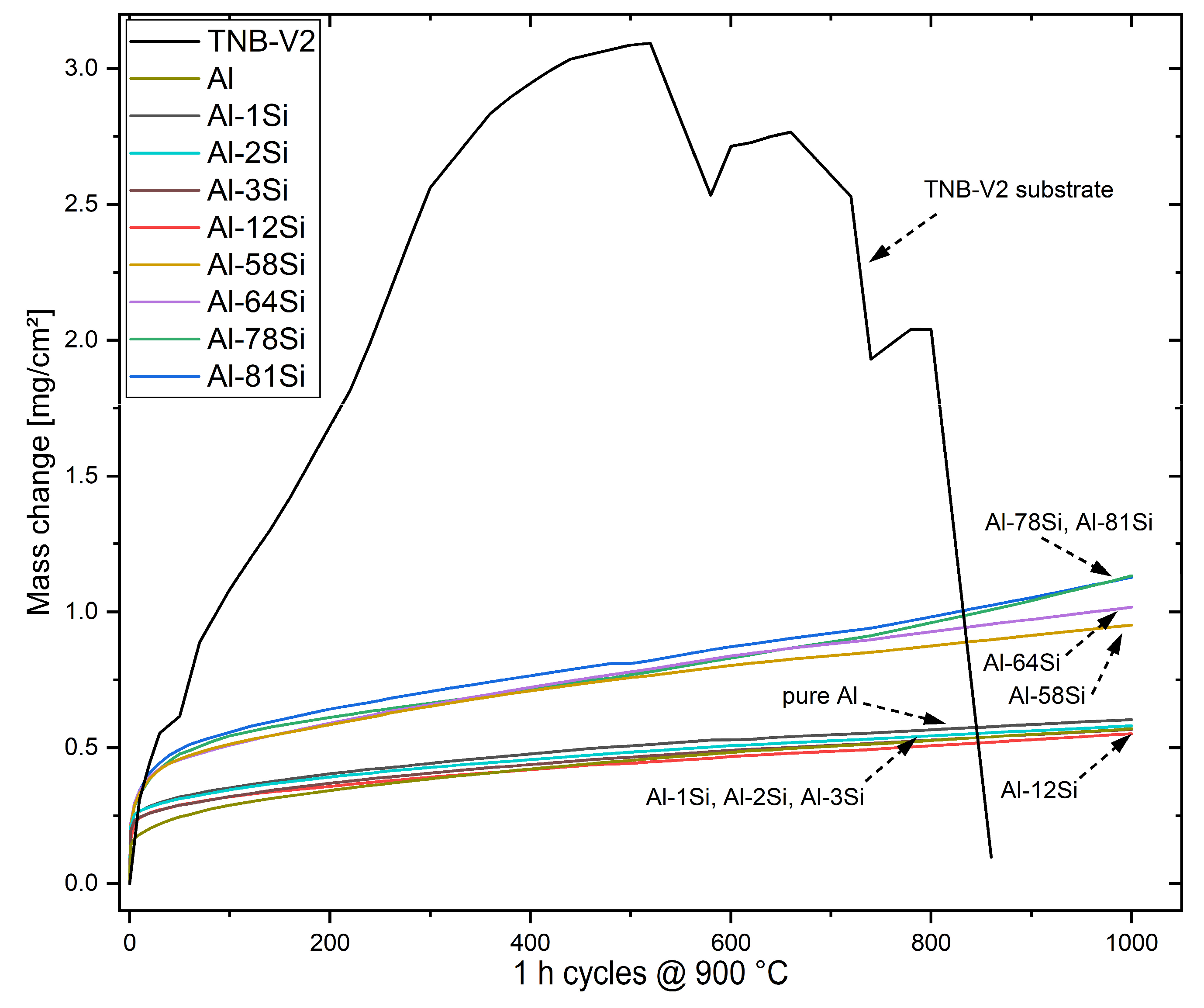
3.2. Thermogravimetric Analysis during Cyclic Oxidation Tests of the Coated TNB-V2 Alloy at 900 °C up to 1000 Cycles in Air

Cyclic oxidation tests were conducted with the different Al-Si-coated and post-heat-treated TNB-V2 alloy samples as well as the bare γ-TiAl-based substrate material at 900 °C for 1000 cycles in laboratory air. Mass gain analyses depending on the number of 1 h cycles were performed and are presented in Figure 4. The uncoated TNB-V2 substrate alloy shows a rapid mass gain up to 3.1 mg/cm² after about 500 cycles, followed by a mass decrease due to spallation of the oxide scale. In contrast, no spallation can be observed for all coated TNB-V2 alloy samples, which show a parabolic mass gain. In Table 3, the parabolic growth rates as well as the mass changes by the initial oxide formations and after 1000 cycles of oxidation are listed. The oxidation curves (Figure 4) can be separated in ≤12 at.% Si, including the pure Al coating and ≥58 at.% Si. The coatings with a Si ≤ 12 at.% and the pure Al coating have the lowest mass gain after 1000 cycles with at most 0.58 mg/cm². The Al-Si coatings with Si ≥ 58 at.% show a significantly higher mass gain by a factor of two after 1000 cycles at 900 °C. In the Si ≤ 12 at.% set of curves, the total mass gain after 1000 cycles increases with decreasing Si content. An exception is the pure Al coating having a mass gain of Δm1000C = 0.57 mg/cm², which is comparable to the mass gain of the Al-3Si coating. The Si ≥ 58 at.% set of curves shows a direct correlation between the Si content and mass gain. Thus, a higher Si content leads to a higher total mass gain after 1000 cycles.
The lowest parabolic growth rate is achieved with the Al-12Si coating (12 at.% Si). With higher Si contents, the growth rate constants are higher by a factor of two and with lower Si contents the constants increase slightly with decreasing Si content. The mass gain by the initial oxidation (Table 3) shows that the pure Al coating has the lowest initial oxidation. By increasing the Si content, the initial mass gain increases. This leads to the observed curve shape: during the first 400 cycles, the pure Al coating shows the lowest mass gain, but with longer oxidation times the lower parabolic growth rate of the Al-12Si coating leads to the lowest total mass gain after 1000 1 h cycles.
The transition of initial oxidation to a stable oxidation occurs after more cycles in case of the Si ≥ 58 at.% coatings. Additionally, the parabolic growth rate is by a factor of two higher for those coatings compared to the lowest parabolic growth rate of the Al-12Si coating. With a Si content below 12 at.%, the growth rate constants increase slightly.
However, most coatings have a mass gain below Δm1000C = 1 mg/cm² after 1000 cycles, which is commonly described as a threshold value for good oxidation resistance [36].

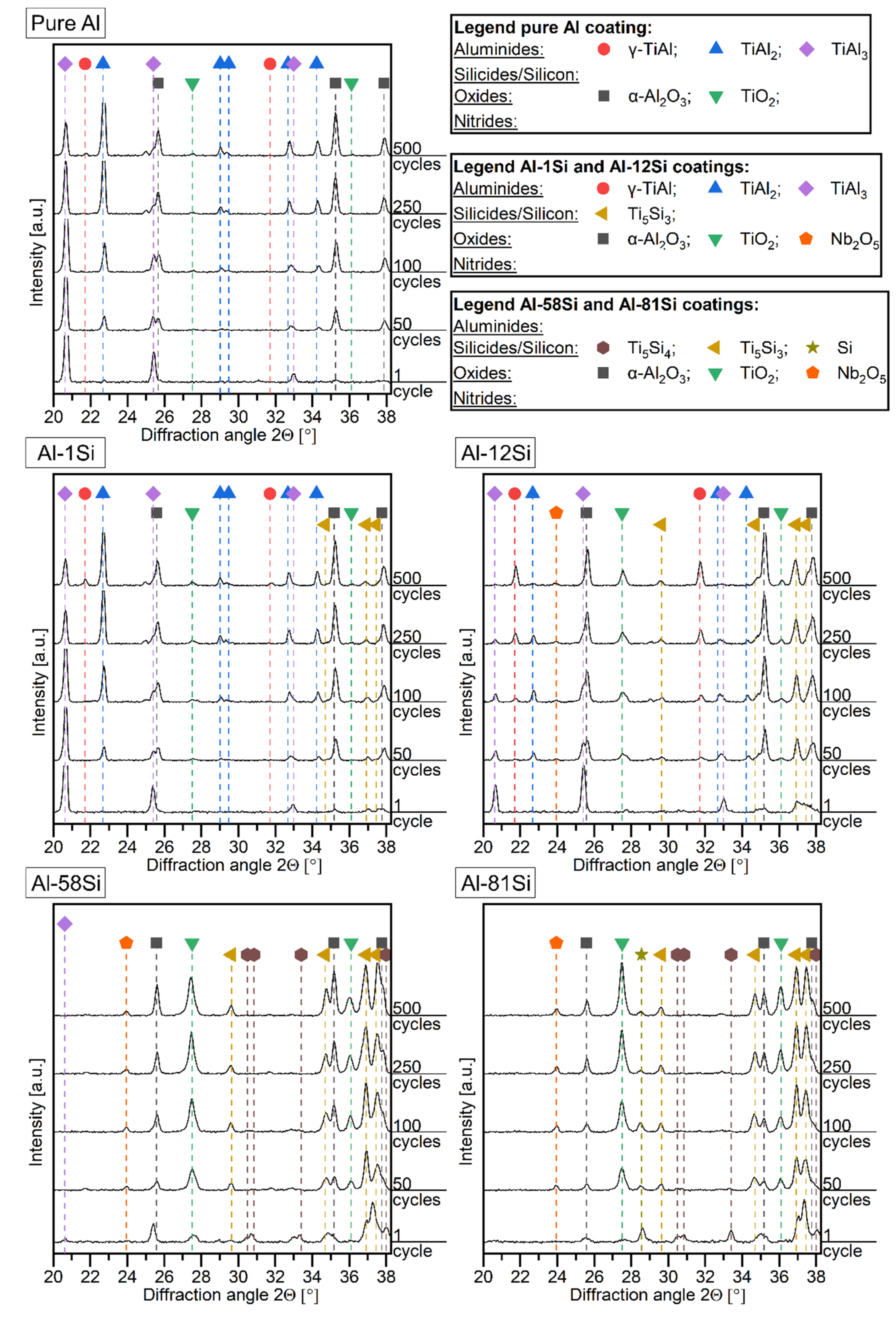
3.3. Oxide Formation as Well as Phase Formation in the Al-Si Coatings on TNB-V2 Alloy during the Initial 500 Cycles at 900 °C

X-ray diffractograms of the different Al-Si coatings after different numbers of cycles are displayed in Figure 5. After just one cycle of oxidation at 900 °C, no pure Al was present in the pure Al and Al-1Si coatings. Therefore, it can be stated that a complete reaction of Al to the TiAl3 (tetragonal, PDF 37-1449) phase occurred. Additionally, traces of the TiAl2 (tetragonal, PDF 47-1177) phase were observed. During further oxidation, TiAl3 transformed completely to the TiAl2 phase. Predominantly α-Al2O3 and traces of TiO2 were found in both coatings. Additionally, traces of the Ti5Si3 phase were detected in the Al-1Si coating after 50 cycles.
The Al-12Si coating consisted of the TiAl3 phase as well as Ti5Si3, which started to form after the first cycle of oxidation but was not yet present after the vacuum heat treatment at 600 °C.
Longer oxidation times led to the transformation of TiAl3 to TiAl2 and eventually to TiAl (tetragonal, PDF 05-0678). The Ti5Si3 phase developed during the first 50 cycles and no changes in the peak intensities were observed during further oxidation. α-Al2O3 as well as TiO2 were formed.
After one cycle of oxidation, the Al-58Si coating formed just a small amount of the TiAl3 phase. The Ti5Si4 (tetragonal, PDF 27-0907) phase was detected besides the majority of the Ti5Si3 phase (hexagonal, PDF 29-1362). The Ti7Al5Si12 phase that was present after vacuum annealing was not detected. Oxides such as Al2O3 and TiO2 were detected after one cycle. The intensity of the Al2O3 peaks was larger in comparison to the TiO2 peaks, indicating a preferential formation of Al2O3 at the beginning of oxidation. After 50 cycles of oxidation, the TiAl3 and Ti5Si4 phases disappeared and the intensity of the TiO2 peaks increased more than that of the Al2O3 peaks. In addition, Nb2O5 was found for the first time after 50 cycles as an additional oxide, whereas no silicon oxide was detected.
In the Al-81Si coating, no Ti7Al5Si12 phase was detected after one cycle of oxidation. Instead, the Ti5Si4, Ti5Si3 and Si phases were present. The Ti5Si4 phase disappeared after 50 cycles of oxidation, whereas the Si phase was still detected after 500 cycles of oxidation. Initially, Al2O3 and TiO2 formed after one cycle. During further oxidation, the intensity of TiO2 peaks increased faster than that of Al2O3, suggesting a preferential oxidation of Ti. From 50 cycles on, Nb2O5 could be detected. SiO2 was absent in the diffractograms even after 500 cycles.
As seen in Figure 4 and Table 3, the Al-Si coatings have a higher initial mass gain than the pure Al coating. Therefore, SEM micrographs of the formed oxide layers in top view were taken after 10 cycles of exposure to 900 °C in air (Figure 6). The pure Al coating has a rough surface which is covered by a furrowed oxide layer. The furrowed oxide layer most likely consists of α-Al2O3 (Figure 6a). Although deeper furrows are present, no cracks are visible. On the Al-1Si and Al-12Si coatings, two regions are visible: one region is characterized by small plate-like oxides, which are most probably θ-Al2O3, and the other region is covered by a smoother oxide, which can be α-Al2O3 (Figure 6b,c). The Al-56Si coating has, comparable to the Al-1Si and Al-12Si, some fuzzy-looking oxides and some regions with more compact, plate-like oxides (Figure 6d). The smoothest oxide surface is exhibited by the Al-81Si coating (Figure 6e). However, it is separated in different islands by a crack network. No plate-like oxides are observed.

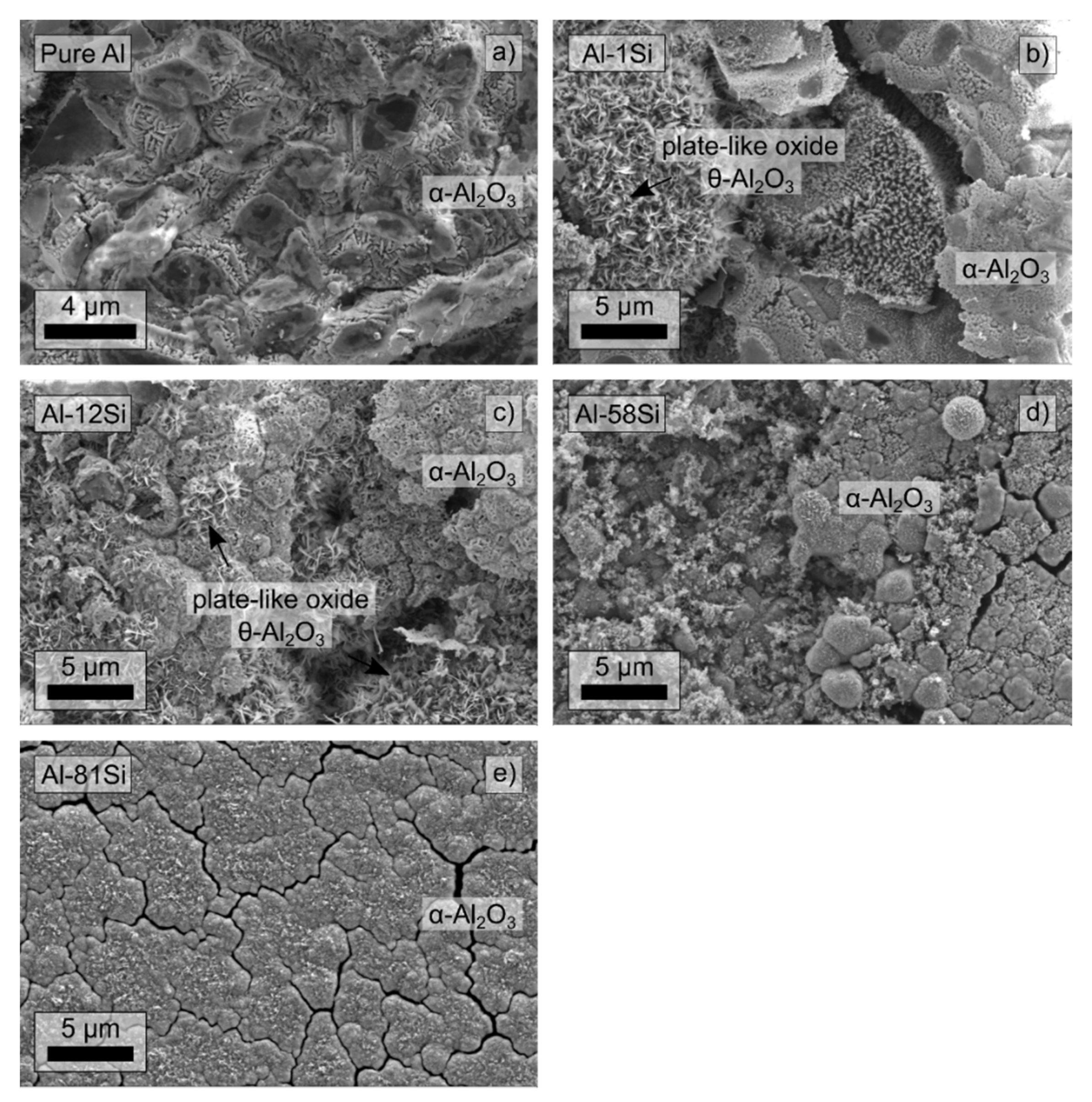
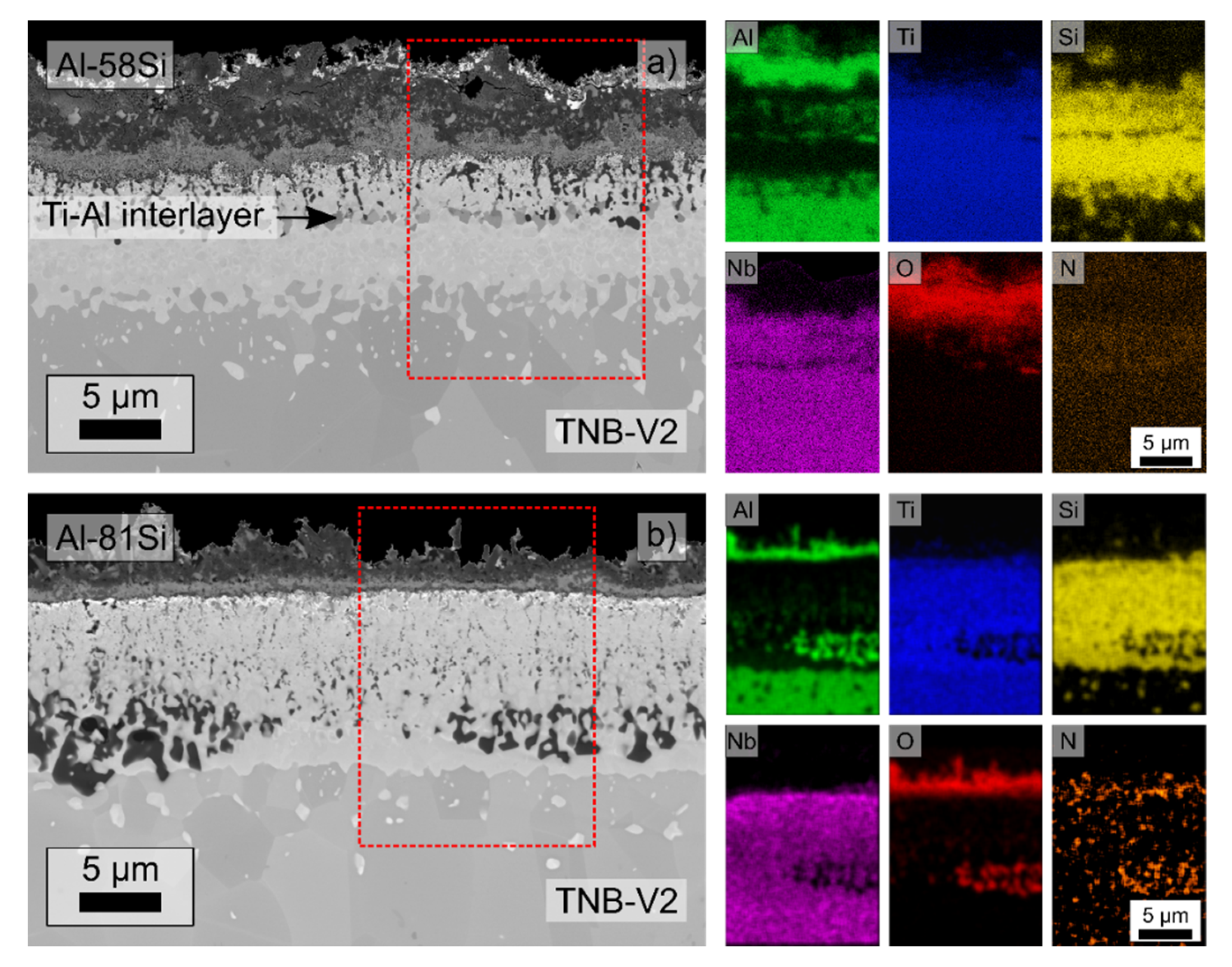
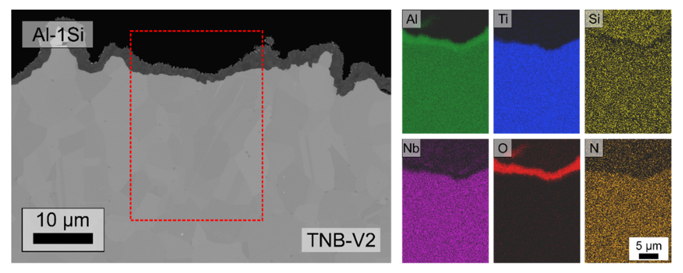
3.4. Microstructure Analysis of the Al-Si Coatings after 1000 Cycles of Exposure to 900 °C

The SEM cross sections as well as the EDX element mappings are displayed in Figure 7 for the pure Al, the Al-1Si and the Al-12Si after oxidizing for 1000 cycles at 900 °C in air. As already recognizable by XRD (Figure 5), in all Al-Si coatings α-Al2O3 is detected. The cross-sectional SEM analyses reveal that the α-Al2O3 is present as a thermally grown oxide (TGO) layer on the surfaces. The TGOs on the pure Al and Al-1Si coatings are dense, compact and uniform (Figure 7a,b). On the Al-12Si sample, the TGOs enclose some bright precipitates of probably Ti5Si3 phase (Figure 7c). Nitrogen is not found in any of the coating nor the TGO by EDS. The thicknesses of the TGOs are on average around 1.6 µm for the pure Al, the Al-1Si and the Al-12Si coatings.
Below the TGO, the pure Al coating consists of the TiAl2 and the (Ti,Nb)Al3 phases. Below the Al-rich phases, TiAl is present. The Al-1Si coating has a comparable structure to the pure Al coating: TiAl2 and (Ti,Nb)Al3 are present below the TGO and γ-TiAl below the Al-rich phases. Additionally, some small, bright Ti5Si3 precipitates are visible in the coating.
In the Al-12Si coating, larger amounts of the bright Ti5Si3 are present adjacent to the γ-TiAl phase. Directly below the TGO, Ti5Si3 is present as an interrupted sub-layer. With a larger depth below the TGO, less Ti5Si3 is visible. Pores are present in the Ti-12Si coating, located close to the TGO.
The SEM cross sections of the Al-58Si and Al-81Si, after oxidation for 1000 cycles at 900 °C, are displayed in Figure 8. The microstructure of the TGOs in the Si-rich (≥58 at.%) coatings varies significantly from the coatings with lower Si contents (≤12 at.%, compared to Figure 7). On both coatings, the TGO consists of an outer and a darker oxide layer, identified as Al2O3, and an inner, brighter oxide layer of TiO2. The TGO on the Al-58Si coating is thicker (~6.5 µm) than the one formed on the Al-81Si coating (~4.0 µm) and around four times thicker than the TGOs on the coatings with Si ≤ 12 at.%. The TiO2 is dense and fine crystalline. Below the TGO, a continuous Ti5Si3 layer is present in both coatings. In the case of the Al-58Si coating, an interrupted Ti-Al layer is present within the Ti5Si3 zone. Based on the EDS mappings, these regions contained Al and thus can be the γ-TiAl phase, although in the XRD scans no γ-phase is detected due to the low penetration depth of the X-rays. Directly below the TGO, the Nb content slightly increases, and bright regions along grain boundaries are visible in both coatings.
Both coatings exhibit dark Al2O3 oxides along the grain boundaries within the Ti5Si3 layer. In the Al-58Si coating, these oxides are mainly present below the interrupted TiAl layer, whereas in the Al-81Si coating these oxides are present within the whole layer. However, the size of the oxides increases closer to the coating/substrate interface.
Besides Ti and Al, Nb and Si are detected within the TGO. Nb can be identified as Nb2O5 by XRD, whereas no SiO2 is detected in XRD. This indicated that the Si is present either as an amorphous SiO2 or partially as a solid solution within rutile (TiO2).
After the cyclic oxidation test at 900 °C for 1000 h in total, the phase composition has changed as shown in the X-ray diffractograms in Figure 9. In all coatings, oxides are present, which are mainly α-Al2O3 and TiO2. However, the intensity of the TiO2 peaks is quite low for the pure Al and the Al-12Si coatings. For the Si ≥ 12 at.% coatings, the peak intensity of the TiO2 increases with increasing Si content.
In the pure Al and Al-1Si coatings, the TiAl3 as well as the TiAl2 phases are still present besides the γ-TiAl phase. In the Al-12Si coating, only the γ-TiAl phase is present. In the Al-58Si and Al-81Si coatings, no γ-TiAl phase is detected by XRD. Instead, the Ti5Si3 phase is present. The same phases can be found in the Al-12Si coating and, with a very low reflex intensity, in the Al-1Si coating. Nb2O5 is present in the Si ≥ 12 at.% coatings as an additional oxide. Peaks of SiO2 are generally not detected in all Al-Si coatings up to the maximal tested time of 1000 h at 900 °C.

3.5. Enhanced Long-Time Cyclic Oxidation Behavior at 900 °C up to 5000 Cycles in Air

In order to obtain a better understanding of the sustainable lifetime and further oxidation processes, cyclic oxidation tests were continued up to 5000 cycles at 900 °C (Figure 10). After 1500 cycles, the Al-12Si coating has an increasing mass gain and the curve deviated from a parabolic course and represented a rather increasing progression. The same behavior is shown by the curves for the Al-58Si and Al-64Si coatings.
In contrast, the mass gain for the coatings with Si < 12 at.% stays low, and the curves have a parabolic progression. The Al-78Si and Al-81Si coatings have a parabolic progression as well, however, with a higher growth rate (Table 4). After 5000 cycles, the total mass gain of all coatings with Si ≤ 3 at.% is still below 0.85 mg/cm², indicating their excellent oxidation resistance on the TNB-V2 alloy (Table 4). Additionally, none of the tested coatings show a dramatic mass loss due to spallation, as well as no breakaway oxidation, unlike the uncoated TNB-V2 substrate in Figure 4.

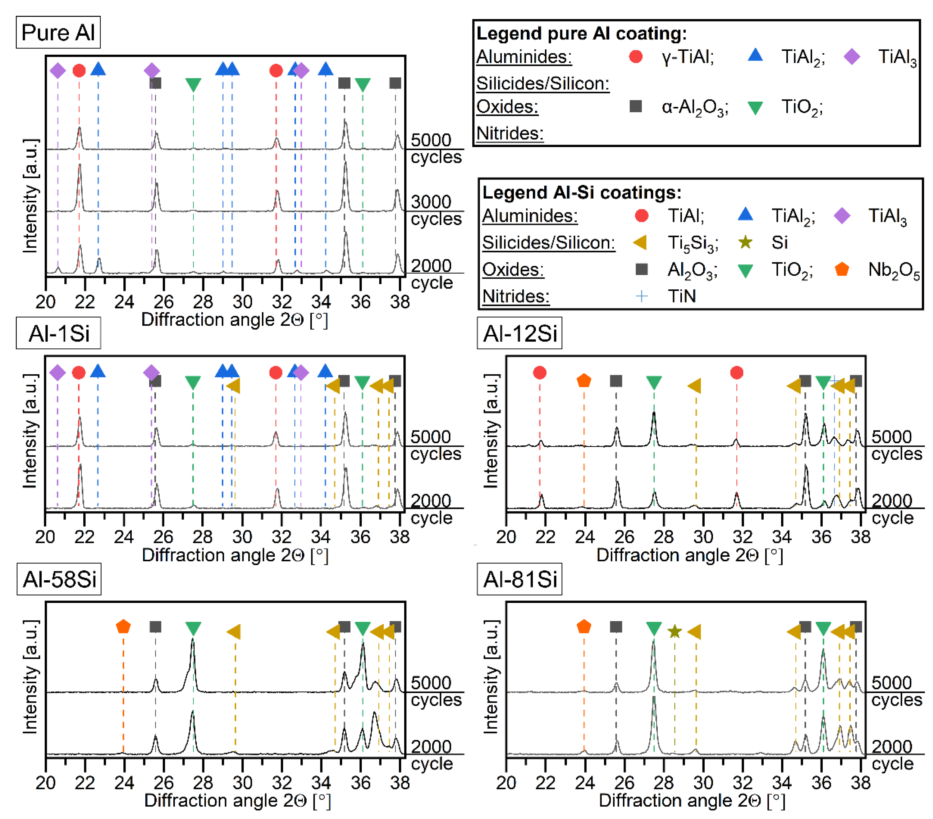
3.6. Phases Formation and Microstructure Changes during 5000 Cycles at 900 °C

The present phases in the Al-Si coatings were tracked in a 1000 cycle frequency by XRD and the representative selected diffractograms shown in Figure 11. The XRDs were tracked for all compositions. However, only the representative coatings of Al-1Si, Al-12Si, Al-58Si and Al-81Si are shown. In the pure Al coating, TiAl3 and TiA2 were still present after 2000 cycles but eventually transformed to the γ-TiAl phase. The intensity of the peaks that are associated to the already-formed oxides of Al and Ti remains nearly unchanged. After 5000 cycles, α-Al2O3 is still the dominant phase.
In the Al-1Si coating, the TiAl3 and TiAl2 phases already transformed into γ-TiAl after 2000 cycles. The Ti5Si3 phase degraded with increasing time. However, due to the low intensity of peaks after 1000 cycles, the precise point in time cannot be identified. No changes in the oxide peaks’ intensity are visible, and the α-Al2O3 oxide is still the main present oxide.
The Al-12Si coating shows mainly increasing TiO2 peak intensities. However, the Al2O3 and TiAl signals decrease only slightly. TiN could also be present, however, due to the proximity of the TiN peak to the peak of the Ti5Si3 phase; this phase is difficult to identify unambiguously. The peaks of the Ti5Si3 phase do not change and Nb2O5 is present in traces.
The surface of the Al-58Si coating is composed mainly of oxides where TiO2 is the main phase. The intensity of the Nb2O5 peak decreases with time during the cyclic oxidation test at 900 °C. This indicates that the Nb2O5 is present below the TiO2. With increasing thickness of TiO2, the penetration depth of the X-rays is insufficient to reach the Nb2O5. The same reason is valid for the Ti5Si3 layer, as its peaks also show a decreasing intensity or even disappear. In contrast, the intensity of the Al2O3 peaks is nearly unchanged. This is due to the fact that the Al2O3 formed above the rutile layer, as shown in Figure 8.
The Al-81Si coating shows a behavior similar to the Al-58Si coating. The main phases are TiO2 and Al2O3, which were already present after 500 cycles (compare to Figure 5). Nb2O5 is still detected after 5000 cycles, but the intensity of its peaks decreases over time. Si disappears after 3000 cycles, and the intensity of the Ti5Si3 peaks decreases due to the growth of the overlying TiO2 phase.
After oxidation for 5000 cycles at 900 °C, the pure Al and the Al-1Si coatings have a very similar appearance. Thus, only the Al-1Si coating is presented in Figure 12. On both coatings, a dense TGO formed and consists of Al2O3 with traces of Ti, most probably in the form of TiO2. No nitride layer is present on both coatings. Below the TGO, the microstructure of both coatings consists homogenously of the γ-TiAl phase without any precipitates. In the Al-1Si coating, the Si content is below the detection limit of EDS and only background noise is detected. Thus, the Si seems to diffuse into the TNB-V2 substrate alloy, leading to an even distribution. In the TGO on the Al-1Si coating, no Si is detected as well. The TGO on the pure Al coating was around 2.7 µm thick and 2.3 µm on the Al-1Si coating.
The cross section of the Al-12Si coating after 5000 cycles of oxidation reveals the formation of oxide nodules in some regions of the coating, whereas other regions are still undamaged (Figure 13). The nodules consist of different oxides. The former Al2O3 layer is still present. However, above are larger grains of TiO2 and below fine crystalline TiO2. Additionally, Nb and Si are present in the TiO2. The XRD results in Figure 11 indicate that Nb is present as Nb2O5, whereas Si can be present in a solid solution or amorphous SiO2. A nitride layer, presumably TiN, is detected beside a silicide layer below the oxide nodule. The undamaged regions of the Al-12Si coating show minor changes after the 5000 cycles (compare to Figure 7). The main phase in the TGO is still Al2O3 with traces of Ti. The thickness of the oxide layer is around 2.2 µm in the undamaged region. Below the TGO, a Ti5Si3 sub-layer formed, which is interrupted only sporadically (Figure 13c). Inside the coating, larger grains of Ti5Si3 within a γ-TiAl matrix are present. Additionally, internal oxides are visible, which are rich in Si. These internal oxides are adjacent to Ti5Si3 phases. Thus, it could be assumed that these oxides are amorphous SiO2. Some regions below the TGO are marked by a higher Ti content.
Cross sections of the Al-58Si and the Al-81Si coatings after 5000 cycles at 900 °C are presented in Figure 14. In the TGO on the Al-58Si coating, a layer of Al2O3 is still present. However, above the Al2O3, larger grains of TiO2 formed and below the Al2O3 a fine crystalline and rather dense TiO2 layer appeared. The average thickness of the TGO on the Al-58Si coating is 11.2 µm (Figure 14a). Below the TGO, a layer of the Ti5Si3 phase is still present with only minor internal oxides of Al2O3 located in the outermost region of the Ti5Si3 layer. The region directly below the TGO is also marked by an enhanced Nb content and bright grain boundaries. Additionally, the content of N is elevated in the same region.
The Al-81Si coating has an outmost Al2O3 layer (Figure 14b). The TiO2, which formed below the Al2O3, is fine crystalline and dense. The total thickness of the TGO is approximately 4.2 µm. The Ti5Si3 layer under the TGO is permeated with internal oxides, which were identified as Al2O3. However, the majority of these oxides are located within the Ti5Si3 layer and only a few penetrate into the substrate. At the TGO/Ti5Si3 interface, a higher amount of Nb was detected, and bright grain boundaries are present as well. In the TNB-V2 substrate, regions with a higher Ti content are visible. No distinctive N-rich region is identified in the Al-81Si coating.

4. Discussion

4.1. Morphology and Phase Formation in the Al-Si-Based Coating after Magnetron Sputtering

The observed morphologies of the Al-Si-based coatings on the γ-TiAl-based TNB-V2 alloy, displayed in the SEM cross sections in Figure 2, were a result of different nucleation and growth mechanisms during the PVD deposition process using DC magnetron sputtering. Additionally, the Al-Si system is eutectic and does not contain any intermetallic phases [37]. This limited the obtained phases to Al and Si, which in turn have only a very limited solubility in each other (maximum 0.016 at.% of Al in Si at 1190 °C and 0.05 at.% of Si in Al at 300 °C [37]).
The pure Al coating showed a homogenous, densely layered structure according to zone two of the Thornton structure model [38], due to the low melting point of Al (Tm,Al) of around 933.15 K (~660 °C) [37] and the substrate deposition temperature (Tsub) of 473.15 K (200 °C), which lead to a Tsub/Tm,Al ratio of 0.51.
The morphology of the Al-1Si coating was very similar to the pure Al coating, except for some grains of Si that were found at the coating/TNB-V2 substrate interface. The Si grain formation exclusively at the interface was a result of a heterogenous nucleation. This form of nucleation was preferred in comparison to the homogenous nucleation due to the smaller required critical nucleus size [39]. This heterogenous nucleation could have taken place at the free surfaces (coating/environment), at the Al grain boundaries or at the coating/substrate interface. The nucleation at the free surfaces could be hindered by the deposition of further atomic layers during the sputtering process leading to a “moving” free surface. Heterogeneous nucleation would also be conceivable at the quadruple Al grain boundaries and triple points within the layer but was not observed in the present work. One explanation would be that during the initial layer formation no suitable grain boundary of the Al matrix was present. However, the coating/substrate interface was an energetically favorable location for nucleation. Thus, the first Si grains formed there. During proceeding deposition, the Si did not form further crystal nuclei. Instead, the Si atoms were diffusing within the layer until it reached the already-formed Si grains at the coating/substrate interface. Therefore, nucleation at the interface seemed to be energetically most favorable.
A similar behavior was also described by McCaldin and Sankur [40] in Al layers on Si substrate. Si precipitates formed at the coating/substrate interface as well as at the free surface within the Al layer after a heat treatment at 530 °C for 1 h [40]. Van Gurp [41] also observed the preferential formation of Si precipitates at the coating/substrate interface in evaporated Al-Si layers (Si content between 0.4 and 1.8 at.%) on a Si wafer. Van Gurp [41] explained the preferential formation at the interface by the fact that this was a large nucleation site.
The nucleation at the coating/substrate interface required a sufficient diffusion speed of Si in Al so the deposited Si could diffuse through the whole coating. In addition to the diffusion that occurred already in situ during the deposition process at around 200 °C, the substrate was cooled down after the deposition to 150 °C in 15 min. Under the assumption of an average temperature of 175 °C during this 15 min, the diffusion length (Dt)1/2 can be estimated to 28.6 µm with the diffusion coefficient (D) taken from the literature [41]. This allows the conclusion to be drawn that the last deposited Si atoms can diffuse from the surface through the maximum of 20 µm of Al-Si coating to the coating/substrate interface and precipitate as Si grains.
The coating morphology achieved in the Al-12Si coating is a result of nucleation of Si at the coating/substrate interface as well as at the quadruple and triple points of grain boundaries and along the grain boundaries themselves in the Al layer. During the first stage of deposition, the diffusion length to the substrate was short; thus, a nucleation at the interface was preferred. However, during longer deposition times, this distance increased. Due to the higher Si content, the necessary amount for nucleation at quadruple grain boundaries and triple points was reached easier than in the Al-1Si coating. The precipitation of Si took place there during longer deposition times, leading to the branched structure. The precipitation of Si along grain boundaries in similar structures was also described in the literature [41].
The Si ≥ 58 at.% coatings had a columnar morphology according to zone one of the structure zone model by Thornton due to the high melting point of Si (Tm,Si = 1687.15 K, 1414 °C [37]) and thus a Tsub/Tm,Si ratio of 0.28.
The Al-81Si coating provided a predominantly amorphous structure, which probably suppressed any Al diffusion or precipitation. Thus, a homogenous, columnar structure with a homogenous Al distribution was formed.
The different coating thicknesses were a result of the different sputtering yields. Compared to Si, the sputtering yield of Al is over two times higher, depending on the Ar+ ion energy [42].

4.2. Phase Evolution during Vacuum Heat Treatment at 600 °C for 20 h

After the deposition process using DC magnetron sputtering PVD, a post heat treatment in a high vacuum atmosphere at 600 °C for 20 h of the different Al-Si coatings was performed. An enhanced surface roughness occurred especially for the coatings with Si ≤ 12 at.% (Figure 3). A higher roughness consequently led to a larger surface, which results in a higher mass gain. Since the roughness was not considered in calculating the samples’ surface area, the obtained mass change values per surface area were overestimated for rougher surfaces. The mechanism for formation of this enhanced surface roughness is displayed in Figure 15 for the pure Al coating and in Figure 16 for the Al-1Si coating.
During the post heat treatment of the pure Al coating, small grains or “pockets” of the TiAl3 phase were formed (Figure 15 t0→t1). A formation of these grains seemed to be energetically more favorable than the formation of a continuous TiAl3 interface as a film due to lower surface energy. During further heat treatment, Al diffused through the TiAl3 grains and reacted with Ti at the TiAl3/TiAl interface to form TiAl3 (Figure 15 t1→t2). Thus, the TiAl3 grains grew to a continuous but unevenly thick interlayer between the pure Al coating and the γ-TiAl substrate. The reaction zone was located at the TiAl3/TiAl interface since the Al diffusion in the TiAl3 phase is faster (D*Al = 27.1 × 10⁻¹⁵ m²/s at 575 °C [43]) than the diffusion of Ti (D*Ti = 1.2 × 10⁻¹⁵ m²/s at 575 °C [43]). Additionally, Thiyaneshwaran et al. [43] observed that the nucleation of the TiAl3 phase takes place preferentially at the TiAl3/Ti interface in Ti-Al diffusion couples due to the Al diffusion being over 20 times faster than the Ti diffusion in the TiAl3 phase. Moreover, the diffusion of Al and Ti in the γ-TiAl phase is nine orders of magnitudes slower than the Al diffusion in the TiAl3 phase. With the values taken from [44], the tracer diffusion coefficients can be calculated to D*Al = 1.9×10⁻²⁴ m²/s and D*Ti =6.2 × 10⁻²² m²/s, respectively, at 575 °C. Therefore, the diffusion processes in the γ-TiAl phase were negligible.
After 20 h of heat treating at 600 °C (Figure 15 t3), the reaction of the pure Al coating to TiAl3 was not finished leaving a rough Al/TiAl3 interface, but the surface of the coating was still flat.
The phase transformations in the Al-1Si coating started with the reaction of Si with the γ-TiAl-based substrate alloy (Figure 16 t0). This reaction led to the formation of similar “pockets” of another phase, as in the pure Al coating. The formed intermediate phase was not analyzed in this work. However, it could be expected that a ternary Ti-Al-Si phase formed, denoted as τ-phase (Figure 16 t0→t1). Such a ternary phase was also the phase that formed first in a Ti/Al-Si diffusion couple investigated from Dezellus et al. [45]. However, due to further diffusion processes, eventually the τ-phase transformed to Ti(Al,Si)3, and additional TiAl3 formed below this zone (Figure 16 t1→t2). The reason for this TiAl3 formation was the same as for the pure Al coating. Al diffused through the Ti(Al,Si)3/TiAl3 and reacted in the reaction zone at the TiAl3/TiAl interface. This led to an upward “movement” of the Si-containing Ti(Al,Si)3. After the heat treatment, the Al was consumed, and the Ti(Al,Si)3 phase was located at the outmost region of the coating (Figure 16 t3), as observed in Figure 3. It is noteworthy that the transformation of the Al-1Si coating to the intermetallic phases was accelerated compared to the pure Al coating. Although the thickness of both coatings was comparable, no remaining Al phase was observed using SEM in the Al-1Si coating after the heat treatment. This indicated an effect of the Si on the diffusion of Al or the reaction of Al with Ti. As shown in [17] for a pack cementation process, the addition of Si to the pack increases the grow rate of aluminide coatings.
A mechanism for the phase formation of Al-12Si and Al-20Si (in wt.%) cold-sprayed coatings on TiAl-based substrate alloy during heat treating was suggested by Wang et al. [46]. According to their mechanism, at the initial time of heat treatment, Si diffused inwards to the substrate and reacted there to an τ2-Ti(AlxSi1-x)2 interlayer. By forming this τ2 phase, Ti was consumed from the substrate, which led to the formation of a Ti(Al,Si)3 layer below the τ2 interlayer. Eventually, the τ2 phase was decomposed by the further inward diffusion of Al from the coating [46]. In a previous work, this mechanism was confirmed by HT-XRD for an Al-18Si (in at.%) magnetron sputtered coating [32]. Therefore, this mechanism seemed to be valid also for the microstructure evolution of the Al-12Si coating during heat treatment. A melting of the coating is less probable due to the low heating rate and the fast reaction of Si with TiAl. Based on our previous work, a heat treatment for 2 h at 550 °C is sufficient for a complete reaction of all the Si from an Al-18Si (in at.%) coating with a TNB-V2 substrate [32].
At the beginning of the heat treatment of the Al-58Si and Al-81Si coatings, the ternary Ti7Al5Si12 phase was formed by inward diffusion of Al and Ti into the coating. The already-present Al in the coating seems to facilitate the diffusion of Al into the coating. In comparison to pure Si coatings on TiAl, no significant inward diffusion of Al into the coating was observed during heat treatment, and instead an Al-enriched layer formed below the coating [47,48].
In the present work, after the formation of the Ti7Al5Si12 phase and with progressing Al and Ti diffusion, Ti7Al5Si12 eventually transformed into Ti(Al,Si)3 and Ti5Si3. Since the Al-58Si contained more Al from the beginning, a more pronounced Ti(Al,Si)3 layer was found.

4.3. Oxidation Behavior of the Pure Al and Al-Si-Based PVD Coatings and the Influence of the Si Contents

In the present work, it was shown that all Al-Si-based coatings deposited by magnetron sputtering greatly improve the oxidation resistance of the γ-TiAl alloy TNB-V2 when exposed at 900 °C up to 5000 cycles. After 1000 cycles, all the Si ≤ 12 at.% coatings had a maximum mass gain of 0.6 mg/cm². This is well below the value of 1 mg/cm² after 1000 cycles, which is the threshold commonly taken for good oxidation resistance [10,36]. From the coatings with Si ≥ 58 at.%, only the one with a Si content of 58 at.% stayed below 1 mg/cm².
The PVD coatings presented in this work had a lower mass gain than the comparable slurry Al-Si coatings produced by Moskal et al. [27] on TiAl48-2-2: the lowest mass gain they observed was 0.9 mg/cm², which showed the Al-12.5Si (in at.%) slurry coating after 500 h of oxidation at 900 °C. The lower mass gain of the magnetron-sputtered coatings in the present work could be a result of the different substrate alloy composition or the heat treatment of the coating. In [27], a diffusion treatment at 950 °C for 4 h in an argon atmosphere was performed, which led to a melting of Al-Si coatings due to the eutectic temperature of 577 °C [37]. As a result, the coatings of [27] exhibited a higher Si content at the coating/surface interface after diffusion treatment. Compared to that, the Si ≤ 12 at.% coatings produced in this work had a higher Si content below the surface of the coating, which could have positively influenced the oxidation behavior.
However, an effect of the substrate is also most likely since Moskal et al. used a TiAl48-2-2 alloy as substrate material, which contains only 2 at.% Nb but additionally 2 at.% Cr, whereas in this work a TNB-V2 was utilized, which contains no Cr but 8 at.% Nb.
In the work of Swadźba et al. [17], pure Al and Al-Si coatings with two different Si contents in the pack were produced by pack cementation on TNB-V5. Due to diffusion processes during the pack cementation, the exact Si content in the coatings could not be determined; therefore, the coatings were named low-Si and high-Si coatings [17]. They observed that the high-Si coating has a lower initial thickness and a higher mass gain after 131 23 h cycles (3013 h in total) at 850 °C than the low-Si coating. The differences in the mass gain are based mainly on the mass gain during the first hours since, after a longer oxidation times, both coatings exhibited logarithmic oxidation kinetics [17]. Due to the different Si distribution in the Al-Si coatings obtained by pack cementation and by sputtering in the present work, a direct comparison is not possible since also no logarithmic growth kinetics was observed in this work. However, a comparison for the pure Al coatings, which eventually formed TiAl3, is possible: Swadźba et al. [17] calculated a parabolic growth rate Kp of 81.46 × 10⁻⁴ mg2/(cm4 h) for the pure aluminide coating tested at 850 °C, which is around half to one order of magnitude larger than the Kp (Table 3 and Table 4) obtained in this work with a 50 °C higher testing temperature. Other Kp values found in the literature for TiAl3 coatings at 900 °C are 32 × 10−5 mg2/(cm4 h) [49] of Chu et al., who produced sputtered Al coatings on a Ti-50Al (at.%) substrate material and heat treated them in a high vacuum atmosphere before cyclic oxidation. In a previous study, a Kp of 28.6 × 10⁻⁵ mg2/(cm4 h) was achieved for a 10 µm thick, magnetron-sputtered Al-30Ti (at.%) coating which was deposited on the same TNB-V2 substrate material with the same sample geometry [34].
These values are all higher than the one obtained in this work. The reason for this could be (besides different substrate alloys) a difference in the thickness of the aluminide coatings. Chu et al. [49] observed that a thicker Al coating eventually transformed into an aluminide layer during heat treatment and exhibited a lower parabolic growth rate compared to a thinner coating. They used Ti-50Al as substrate material and tested the coated samples at 900 °C in cyclic oxidation tests. The obtained Kp for a 3 µm thick Al film was 709 × 10−5 mg2/(cm4 h), while for the aforementioned 5 µm thick Al film, which led to an 8 µm thick TiAl3 layer, a Kp value of 32 × 10−5 mg2/(cm4 h) was observed [49].
However, thin Al/aluminide coatings can suffer from a depletion of Al, which leads to an insufficient oxidation resistance after a certain time marked by a linear mass gain [17] or breakaway oxidation [34,49]. This was not observed in this work for the initially 22.2 µm thick pure Al coating, which showed excellent oxidation resistance for 5000 cycles at 900 °C.
For Al-Si coatings on γ-TiAl-based alloys, no Kp values at 900 °C are provided in the literature. However, in this work the calculated Kp values for the Al-Si are all within the range of reported values of TiAl3-based coatings, which is due to the large amount of this phase in the layers. The additional Ti5Si3 phase, which is present in the Al-Si coatings, can have a linear growth rate but also a parabolic rate depending on the actual composition. However, Kp values can be as low as 2 × 10⁻⁵ mg2/(cm4 h) for Ti5Si3.2 at 1000 °C [50].
Compared to the pure Al coating, the Si < 12 at.% coatings have a lower Kp, indicating a better oxidation resistance. However, due to the higher initial mass gain (mi) of the Si < 12 at.% coatings, their total mass gain after 5000 cycles is higher than one of the pure Al coatings. In contrast, high Si contents (≥ 58 at.%) led to an increased oxidation rate and the associated mass gain. Therefore, the oxidation behavior of the different Al-Si coatings will be separately discussed in the following sections for the Si ≤ 12 at.% and high Si ≥ 58 at.% contents.

4.3.1. Oxidation Behavior of Al and Al-Si with ≤ 12 at.% Si PVD Coatings

After the vacuum heat treatment, TiAl3 was the predominant phase in the pure Al coating as well as in the Al-Si coating with a Si content of 12 at.% and below (Figure 3). At this stage, Si was mainly dissolved in the Ti(Al,Si)3 phase. In the literature, a maximum solubility of Si in the Ti(Al,Si)3 phase is stated to be around 15 at.% [51]. At high temperature exposures, α-Al2O3 forms as a protective layer on the surface as described in the literature for both the TiAl3 and the Ti(Al,Si)3 phases [11,12,32,52,53]. Due to the Al2O3 formation, Al is consumed from the TiAl3 phase, and a conversion from TiAl3 to the TiAl2 phase occurs. The TiAl2 phase, however, provides only a low solubility of Si [51]. Therefore, a direct transformation of Ti(Al,Si)3 to TiAl2 is not possible. Instead, the Ti5Si3 phase forms additionally with the Si provided by the former Ti(Al,Si)3 phase. The required Ti is also provided by the Ti(Al,Si)3 phase, which releases Ti when Al is consumed during oxidation. When the Si is consumed from the Ti(Al,Si)3, leading to the formation of TiAl3, the transformation into TiAl2 eventually occurs. Therefore, the reaction scheme can be qualitatively written as:
Ti ( Al , Si ) 3 + O 2   TiAl 3 + Ti 5 Si 3 + Al 2 O 3 + O 2   TiAl 2 + Ti 5 Si 3 + Al 2 O 3
Eventually, all Si is used for the formation of the Ti5Si3 phase, and the TiAl2 phase starts to form. The microstructure composed of the TiAl2 and Ti5Si3 phases can also lead to a sufficient oxidation protection on TiAl-based alloys [12].
When the Si is present only in the Ti5Si3 phase, a direct influence of Si on the phase transformation seems unlikely, since Ti5Si3 is a thermodynamically stable phase, and TiAl2 and γ-TiAl have a very low solubility of Si with maximum values of 0.5 at.% [32,51]. However, it was shown that the Ti5Si3 phase hinders interdiffusion processes between a Ti-30Al (in at.%) coating and the TNB-V2 and TiAl48-2-2 substrate alloys when applied as a continuous layer and therefore slows down the Al depletion [34]. In the literature, the segregation of the Ti5Si3 phase along the grain boundaries can be found for different Al-Si-based coatings [31,33]. These Ti5Si3 precipitates could effectively slow down the grain boundary diffusion of Al. In the Al-12Si coating, a segregation of Ti5Si3 at the grain boundaries was observed as well, so this is a plausible mechanism of an increased oxidation resistance for this coating composition. Additionally, a Ti5Si3 sublayer formed below the TGO in the Al-12Si coating, which could have additional beneficial properties in terms of oxidation, according to Novák et al. [28]. However, they did not provide any further explanation on the mechanism.
Ti5Si3 has a maximum solubility of Al around 3 at.% at 900 °C [54]. The dissolution of Al in Ti5Si3 in Al-Si-based coatings was also described by Swadźba et al. [19]. In their Si-aluminide coatings, the only oxide formed close to the Al containing Ti5Si3 grains was Al2O3, whereas neither SiO2 nor TiO2 were observed [17,19]. This indicates that Al containing Ti5Si3 is able to form Al2O3, which could be the reason why a Ti5Si3 sublayer can enhance the oxidation resistance.
However, for Al-Si layer with lower Si contents (≤3 at.%), as investigated in this work, the segregation of the Ti5Si3 phase took place as small precipitates. These precipitates were still located at grain boundaries but did not form a continuous seal or a sublayer below the TGO. Therefore, the effect of the Ti5Si3 phase on the oxidation behavior seems negligible or not present for lower Si contents (≤3 at.%) after the Ti5Si3 formation.
Other hypotheses described in the literature include that Si dissolves in rutile, resulting in a slower oxygen diffusion [22,23]. Since Si could not be detected in the TGO formed on the Si ≤ 12 at.% coatings, which also consisted mainly of Al2O3 with only traces of TiO2, this effect is therefore unlikely in the present work. The same applies to the statement that small SiO2 particles in rutile prevent recrystallization and delamination [23,24,25], since no major amounts of rutile were formed.
Since the Al-Si coatings with a very low Si content (≤ 3 at.%) tend to have a lower parabolic growth rate constant but a higher initial mass gain, it can be concluded that this is caused by an effect during the beginning of the oxidation process. Although the Si content is quite low (1–3 at.%) after deposition, the Si distribution after heat treatment plays an important part. In the Al-1Si coating, the Si was present in a rather thin region at the outmost part of the layer after heat treatment (Figure 3b). This led to a Si content as high as 5 at.% in this region, which could have an influence on the oxidation process. As described earlier, Si has a stabilizing effect on the TiAl3 phase during oxidation, due to the Ti gettering by the formation of the Ti5Si3 phase. However, TiAl3 could also form the transient θ-Al2O3 oxide, which is known to be a fast-growing polymorph of Al2O3 [12,17,55]. In comparison, theTiAl2 phase forms exclusively the desired α-Al2O3 [12]. Therefore, the Si content in the region below the TGO could stabilize the TiAl3 phase for a longer time, compared to the pure Al coating. This in turn led to a more pronounced or longer formation of θ-Al2O3 (Figure 6), which is characterized by a high growth rate and thus a higher initial mass gain (Figure 4 and Figure 10, Table 3 and Table 4). During prolonged cyclic oxidation tests at 900 °C, the θ-Al2O3 transformed into the stable and slow-growing α-Al2O3. However, after α-Al2O3 formed from θ-Al2O3, the estimated parabolic growth rates were lower in comparison to the pure Al coating, which did not exhibit θ-Al2O3 formation (Figure 6). This mechanism was also described in previous work for Si-Al coatings produced by a pack cementation process with different Si contents, which showed a similar behavior and a lower parabolic growth rate with higher Si contents [17]. Thus, this mechanism seems to be favorable in order to explain a positive effect of Si contents of 3 at.% or lower on the oxidation behavior of Al-Si coatings.
During the 5000 cycles of oxidation at 900 °C, the Al-12Si coating showed a linear increase in mass after roughly 1500 cycles (Figure 10). This was due to the formation of oxide nodules, which consisted of primarily TiO2 (Figure 11 and Figure 13). However, no oxide spallation occurred. This can be due to the formation of SiO2 within the TiO2 leading to a densification of the TGO without grain growth and a stronger scale adherence [23,24,25]. The reason for the oxide nodule formation is the lower coating thickness of the Al-12Si coating in comparison to the Si ≤ 3 at.% coatings (compare to Table 2) and the accompanied depletion of Al in the region below the TGO. This in turn promotes the formation of TiO2 instead of Al2O3. A depletion of Al in Al-rich coatings with thicknesses of a maximum of 10 µm was also observed in the literature [17,34,49]
In summary, it can be concluded that Si additions of 12 at.% and below in aluminide coatings increase the initial mass gain. At the same time, the estimated parabolic growth rate is reduced after the initial oxide scale formation. No correlation between Si content and parabolic growth rate constants, as well as the initial mass gains, can be established for the lowest Si-containing coatings (Al-1Si, Al-2Si and Al-3Si). This can be due to the small Si contents, as well as the uncertainty of the EDX measurements.

4.3.2. Oxidation Behavior of Si ≥ 58 at.% Al-Si Coatings

With Si contents of at least 58 at.%, the oxidation behavior of Al-Si coatings is mainly influenced by the oxidation kinetics of the Ti5Si3 phase, which is the main phase. This led to a larger mass gain in comparison to the coatings with a Si content of 12 at.% and lower (Figure 4). Prior to the oxidation tests, after the post-vacuum heat treatment at 600 °C, the Al-58Si and Al-81Si coatings consisted of the Ti7Al5Si12 as well as the Ti(Al,Si)3 phase (Figure 3). After one cycle of oxidation at 900 °C in air, the Ti7Al5Si12 phase was completely dissolved, and the Ti5Si3 phase and traces of the Ti5Si4 phase were formed instead (Figure 5). In the Al-81Si coating, elemental Si was present as well, which most likely was released Si from the surplus of Si in the Ti7Al5Si12 (50 at.% Si) phase when it transformed into Si-poorer phases such as Ti5Si3 (37.5 at.% Si) and Ti5Si4 (44.4 at.% Si). Additionally, elemental Si can form during the oxidation at 1000 °C of the Ti5Si3 phase, as shown in the literature [50]. In the Al-58Si coating, no Si formation was observed, which is most probably due to a lower overall Si content and a higher amount of the TiAl3 phase, which getters the released Si [32]. The eventually formed Ti5Si3 phase can have good [29,30] or poor oxidation resistance [56] depending on the exact chemical composition [50,57]. On the one hand, the activities of Ti and Si change for several magnitudes within the homogeneity range of the Ti5Si3 phase [58,59]. Therefore, the formed oxide can change from SiO2 from the Si-rich Ti5Si3 to TiO2 from the Ti-rich Ti5Si3. On the other hand, interstitial elements such as O or C also have a positive effect on the oxidation behavior of Ti5Si3 due to a reduced TiO2 formation [50]. Additionally, the atmosphere of lab air can also reduce the oxidation resistance of Ti5Si3. In the presence of nitrogen, TiN is formed and the nitridation eventually leads to severe oxidation [57,59]. In the present work, different oxidation behaviors were observed for the Ti5Si3 phase. At the air/coating interface, where nitrogen was also detected in the EDX maps in the Al-58Si coating (Figure 14), the Ti5Si3 phase formed TiO2 with traces of SiO2. Due to the lack of a continuous SiO2 layer, the oxidation resistance was poor in this region. As a result, the Ti5Si3 layer was slowly consumed by the formation of TiO2. This process resulted in a high mass gain. However, no spallation of the rather thick oxide scale was observed up to the maximal testing time of 5000 cycles at 900 °C, indicating an excellent adhesion of the TGO. The most likely reason for this is the presence of SiO2, which is reported to lead to a densification of TiO2, increasing its adherence to the base material [23,24,25]. This can also be seen by the fact that the Si-free TiO2, which formed above the Al2O3 on the Al-58Si coating, had a larger grain size then the TiO2 below the Al2O3, which contained Si (Figure 14). On the other hand, the Nb-rich regions directly below the TGO could also enhance the oxidation resistance since Nb is known to increase the oxide scale adhesion on γ-TiAl alloys [20]. Since (Ti,Nb)5Si3 can dissolve up to 21 at.% of Nb [60], a similar effect could take place for the adhesion of an oxide scale on the Ti5Si3 phase as well.
Within the formed Ti5Si3 layer of the Al-Si coatings, some internal oxides were developed that were identified by EDX and XRD as α-Al2O3 (Figure 9, Figure 8, Figure 11 and Figure 14). Fröhlich et al. [47] observed internal Al2O3 formation in a Ti5Si3 layer on TiAl as well. They explained the formation of these oxides as a result of the preferential inward oxygen diffusion along the grain boundaries [47]. Additionally, it was also shown in a previous work that the diffusion of Al in Ti5Si3 takes place at the grain boundaries as well, in particular in the presence of Nb [34].
In this work, internal oxides were found within the whole Ti5Si3 layer of the Al-81Si coating, while in the case of the Al-58Si coating the oxides were present only in the region above the former Ti(Al,Si)3 interlayer (compare to Figure 3, Figure 8 and Figure 14). This indicates that the Al-rich Ti(Al,Si)3 phase further suppresses the inward diffusion of oxygen by reacting with it and forming Al2O3. However, in the case of the Al-81Si coating, the first Al-rich phase is the γ-TiAl phase in the substrate.
Another observation that is worth mentioning is the difference in the oxide scale thickness and mass gains of the Al-58Si and Al-81Si coatings. The highest mass gain was measured for the Al-81Si coating, whereas the oxide thickness was highest for the Al-58Si coating. This indicates that the mass gain of the Al-81Si coating is influenced by the internal oxide formation of Al2O3. In contrast, the mass gain of the Al-58Si coating is mainly a consequence of the formation of a thermally grown oxide layer on the surface. It can be concluded that the Ti(Al,Si)3 interlayer, which formed within the Ti5Si3 layer in the Al-58Si coating, effectively slows down the oxidation rate by blocking internal oxidation below this interlayer, leading to a lower mass gain. In general, a high Si content (≥58 at.%) leads to the formation of a Ti5Si3 layer, which can provide reasonable oxidation protection for γ-TiAl alloys and excellent oxide scale adhesion. However, lower Si contents of 12 at.% and below in Al-Si coatings lead to better oxidation resistance.

5. Conclusions

In this study, DC magnetron sputtering was used to produce a pure Al coating, as well as Al-Si coatings with Si contents from 1 to 81 at.% on a γ-TiAl TNB-V2 alloy. The oxidation behavior was investigated during cyclic oxidation tests with regard to the influence of the different Si contents. The main findings are summarized below:
  • The Al, as well as the Al-Si-based coatings, exhibited significantly improved oxidation resistance compared to pristine TNB-V2 due to the thermal growth of a protective alumina layer and hence diffusion-controlled growth rates.
  • Al and Al-Si coatings with up to 12 at.% Si exhibited a dense morphology. Al-Si coatings with 58 or more at.% Si provide a columnar coating structure.
  • Si addition increased the transformation rate of the pure Al and Si in the as-coated state to the intermetallic phases of Ti7Al5Si12 and Ti(Al,Si)3 during heat treatment and prolonged the formation of metastable γ-Al2O3.
  • During cyclic oxidation testing, the Al coating and Al-Si coatings with Si ≤ 3 at.% both exhibited excellent oxidation behaviors, forming stable and slow-growing alumina scales with mass gains below 0.82 mg/cm² after 5000 cycles.
  • The lowest mass gain after 1000 cycles was exhibited by the Al-12Si (in at.%) coating. However, during longer oxidation times (up to 5000 cycles), the onset of TiO2 formation was observed, which led to a linear mass gain. This is attributed mainly to the lower coating thickness for Al-12Si coating compared to the coatings with ≤3 at.% Si.
  • Si addition of at least 58 at.% in Al-Si coatings led to poor oxidation resistance, as marked by a mass increase above 1 mg/cm². Nonetheless, even these coatings still provide better oxidation behavior than the bare TiAl alloy. No severe spallation up to 5000 cycles at 900 °C was detected.
  • An optimal oxidation resistance can be achieved with Al-Si coatings of at least 13 µm and up to 12 at.% Si.

Author Contributions

Conceptualization, P.-P.B.; funding acquisition, N.L.; investigation, P.-P.B. and L.K.; methodology, P.-P.B.; visualization, P.-P.B.; writing—original draft, P.-P.B.; writing—review and editing, L.K., R.S. and N.L. All authors have read and agreed to the published version of the manuscript.

Funding

This work was financially supported by Deutsche Forschungsgemeinschaft (DFG), Germany, under contract SCHU 1372/6-1 and the National Science Centre, Poland, under contract UMO-2016/23/G/ST5/04128 within the Beethoven II program/TiAlMET project.

Institutional Review Board Statement

Not applicable.

Informed Consent Statement

Not applicable.

Data Availability Statement:

The raw and processed data required to reproduce these findings are available on request to [email protected].

Acknowledgments

The authors would like to thank J. Brien and F. Kreps for the scientific and technical support at the German Aerospace Center, as well as R. Anton, J. Haubrich and U. Schulz from the German Aerospace Center for comments that greatly improved the manuscript.

Conflicts of Interest

The authors declare no conflict of interest.

References

  1. Bewlay, B.P.; Nag, S.; Suzuki, A.; Weimer, M.J. TiAl alloys in commercial aircraft engines. Mater. High Temp. 2016, 33, 549–559. [Google Scholar] [CrossRef]
  2. Kim, Y.-W.; Kim, S.-L. Advances in Gammalloy Materials–Processes–Application Technology: Successes, Dilemmas, and Future. JOM 2018, 70, 553–560. [Google Scholar] [CrossRef] [Green Version]
  3. Clemens, H.; Mayer, S. Design, Processing, Microstructure, Properties, and Applications of Advanced Intermetallic TiAl Alloys. Adv. Eng. Mater. 2013, 15, 191–215. [Google Scholar] [CrossRef]
  4. Vaidya, R.U.; Park, Y.S.; Zhe, J.; Gray, G.T.; Butt, D.P. High-Temperature Oxidation of Ti-48Al-2Nb-2Cr and Ti-25Al-10Nb-3V-1Mo. Oxid. Met. 1998, 50, 215–240. [Google Scholar] [CrossRef]
  5. Dettenwanger, F.; Schumann, E.; Ruhle, M.; Rakowski, J.; Meier, G.H. Microstructural Study of Oxidized γ-TiAl. Oxid. Met. 1998, 50, 269–307. [Google Scholar] [CrossRef]
  6. Swadźba, R.; Marugi, K.; Pyclik, Ł. STEM investigations of γ-TiAl produced by additive manufacturing after isothermal oxidation. Corros. Sci. 2020, 169, 108617. [Google Scholar] [CrossRef]
  7. Brady, M.P.; Brindley, W.J.; Smialek, J.L.; Locci, I.E. The oxidation and protection of gamma titanium aluminides. JOM 1996, 48, 46–50. [Google Scholar] [CrossRef] [Green Version]
  8. Lasalmonie, A. Intermetallics: Why is it so difficult to introduce them in gas turbine engines? Intermetallics 2006, 14, 1123–1129. [Google Scholar] [CrossRef]
  9. Yang, M.-R.; Wu, S.-K. Oxidation resistance improvement of TiAl intermetallics using surface modification. Bull. Coll. Eng. 2003, 89, 3–19. [Google Scholar]
  10. Pflumm, R.; Friedle, S.; Schütze, M. Oxidation protection of γ-TiAl-based alloys—A review. Intermetallics 2015, 56, 1–14. [Google Scholar] [CrossRef]
  11. Smialek, J.L.; Gedwill, M.A.; Brindley, P.K. Cyclic oxidation of aluminide coatings on Ti3Al+Nb. Scr. Metall. Mater. 1990, 24, 1291–1296. [Google Scholar] [CrossRef]
  12. Gauthier, V.; Dettenwanger, F.; Schütze, M.; Shemet, V.; Quadakkers, W.J. Oxidation-Resistant Aluminide Coatings on γ-TiAl. Oxid. Met. 2003, 59, 233–255. [Google Scholar] [CrossRef] [Green Version]
  13. Xiang, Z.D.; Rose, S.R.; Burnell-Gray, J.S.; Datta, P.K. Co-deposition of aluminide and silicide coatings on γ-TiAl by pack cementation process. J. Mater. Sci. 2003, 38, 19–28. [Google Scholar] [CrossRef]
  14. Xiang, Z.D.; Rose, S.R.; Datta, P.K. Codeposition of Al and Si to form oxidation-resistant coatings on γ-TiAl by the pack cementation process. Mater. Chem. Phys. 2003, 80, 482–489. [Google Scholar] [CrossRef]
  15. Swadzba, L.; Maciejny, A.; Mendala, B.; Moskal, G.; Jarczyk, G. Structure and resistance to oxidation of an Al-Si diffusion coating deposited by Arc-PVD on a TiAlCrNb alloy. Surf. Coat. Tech. 2003, 165, 273–280. [Google Scholar] [CrossRef]
  16. Swadzba, L.; Moskal, G.; Hetmanczyk, M.; Mendala, B.; Jarczyk, G. Long-term cyclic oxidation of Al-Si diffusion coatings deposited by Arc-PVD on TiAlCrNb alloy. Surf. Coat. Tech. 2004, 184, 93–101. [Google Scholar] [CrossRef]
  17. Swadźba, R.; Swadźba, L.; Mendala, B.; Bauer, P.-P.; Laska, N.; Schulz, U. Microstructure and cyclic oxidation resistance of Si-aluminide coatings on γ-TiAl at 850 °C. Surf. Coat. Technol. 2020, 403, 126361. [Google Scholar] [CrossRef]
  18. Xiong, H.-P.; Mao, W.; Xie, Y.-H.; Ma, W.-L.; Chen, Y.-F.; Li, X.-H.; Li, J.-P.; Cheng, Y.-Y. Liquid-phase siliconizing by Al–Si alloys at the surface of a TiAl-based alloy and improvement in oxidation resistance. Acta Mater. 2004, 52, 2605–2620. [Google Scholar] [CrossRef]
  19. Swadźba, R.; Swadźba, L.; Mendala, B.; Witala, B.; Tracz, J.; Marugi, K.; Pyclik, Ł. Characterization of Si-aluminide coating and oxide scale microstructure formed on γ-TiAl alloy during long-term oxidation at 950 °C. Intermetallics 2017, 87, 81–89. [Google Scholar] [CrossRef]
  20. Kim, B.G.; Kim, G.M.; Kim, C.J. Oxidation behavior of TiAl-X (X = Cr, V, Si, Mo or Nb) intermetallics at elevated temperature. Scr. Metall. Mater. 1995, 33, 1117–1125. [Google Scholar] [CrossRef]
  21. Maki, K.; Shioda, M.; Sayashi, M.; Shimizu, T.; Isobe, S. Effect of silicon and niobium on oxidation resistance of TiAl intermetallics. Mater. Sci. Eng. A 1992, 153, 591–596. [Google Scholar] [CrossRef]
  22. Vojtech, D.; Mort’aniková, M.; Novák, P. Kinetic and Thermodynamic Aspects of High-Temperature Oxidation of Selected Ti-Based Alloys. In Defect and Diffusion Forum; Trans Tech Publications Ltd.: Freienbach, Switzerland, 2007; Volume 263, pp. 123–128. [Google Scholar]
  23. Chaze, A.M.; Coddet, C. Influence of silicon on the oxidation of titanium between 550 and 700 °C. Oxid. Met. 1987, 27, 1–20. [Google Scholar] [CrossRef]
  24. Chaze, A.M.; Coddet, C. Influence of the nature of alloying elements on the adherence of oxide films formed on titanium alloys. Oxid. Met. 1987, 28, 61–71. [Google Scholar] [CrossRef]
  25. Alford, N.M.; Birchall, J.D.; Kendall, K. Overview—Engineering Ceramics—The Process Problem. Mater. Sci. Technol. 1986, 2, 329–336. [Google Scholar] [CrossRef]
  26. Zheng, N.; Quadakkers, W.J.; Gil, A.; Nickel, H. Studies concerning the effect of nitrogen on the oxidation behavior of TiAl-based intermetallics at 900 °C. Oxid. Met. 1995, 44, 477–499. [Google Scholar] [CrossRef]
  27. Moskal, G.; Migas, D.; Mendala, B.; Kałamarz, P.; Mikuśkiewicz, M.; Iqbal, A.; Jucha, S.; Góral, M. The Si influence on the microstructure and oxidation resistance of Ti-Al slurry coatings on Ti-48Al-2Cr-2Nb alloy. Mater. Res. Bull. 2021, 141, 111336. [Google Scholar] [CrossRef]
  28. Novák, P.; Kříž, J.; Michalcová, A.; Vojtech, D. Microstructure Evolution of Fe-Al-Si and Ti-Al-Si Alloys during High-Temperature Oxidation. Mater. Sci. Forum 2014, 782, 353–358. [Google Scholar] [CrossRef]
  29. Taniguchi, S.; Minamida, T.; Shibata, T. Oxidation Behaviour of Ti5Si3 at Temperatures between 1400 and 1700 K. Mater. Sci. Forum 1997, 251–254, 227–234. [Google Scholar] [CrossRef]
  30. Mitra, R.; Rao, V.V.R. Elevated-temperature oxidation behavior of titanium silicide and titanium silicide-based alloy and composite. Metall. Mater. Trans. A 1998, 29, 1665–1675. [Google Scholar] [CrossRef]
  31. Wang, J.; Kong, L.; Wu, J.; Li, T.; Xiong, T. Microstructure evolution and oxidation resistance of silicon-aluminizing coating on γ-TiAl alloy. Appl. Surf. Sci. 2015, 356, 827–836. [Google Scholar] [CrossRef]
  32. Bauer, P.-P.; Laska, N.; Swadźba, R. Increasing the oxidation resistance of γ-TiAl by applying a magnetron sputtered aluminum and silicon based coating. Intermetallics 2021, 133, 107177. [Google Scholar] [CrossRef]
  33. Huang, J.; Zhao, F.; Cui, X.; Wang, J.; Xiong, T. Long-term oxidation behavior of silicon-aluminizing coating with an in-situ formed Ti5Si3 diffusion barrier on γ-TiAl alloy. Appl. Surf. Sci. 2022, 582, 152444. [Google Scholar] [CrossRef]
  34. Bauer, P.-P.; Swadźba, R.; Klamann, L.; Laska, N. Aluminum diffusion inhibiting properties of Ti5Si3 at 900 °C and its beneficial properties on Al-rich oxidation protective coatings on γ-TiAl. Corros. Sci. 2022, 201, 110265. [Google Scholar] [CrossRef]
  35. Pieraggi, B. Calculations of parabolic reaction rate constants. Oxid. Met. 1987, 27, 177–185. [Google Scholar] [CrossRef]
  36. Schütze, M. The Role of Surface Protection for High-Temperature Performance of TiAl Alloys. JOM 2017, 69, 2602–2609. [Google Scholar] [CrossRef]
  37. Murray, J.L.; McAlister, A.J. The Al-Si (Aluminum-Silicon) system. Bull. Alloy. Phase Diagr. 1984, 5, 74. [Google Scholar] [CrossRef]
  38. Thornton, J.A. Influence of apparatus geometry and deposition conditions on the structure and topography of thick sputtered coatings. J. Vac. Sci. Technol. 1974, 11, 666–670. [Google Scholar] [CrossRef]
  39. Kelton, K.F.; Greer, A.L. Chapter 6—Heterogeneous Nucleation. In Pergamon Materials Series; Kelton, K.F., Greer, A.L., Eds.; Elsevier: Amsterdam, The Netherlands, 2010; pp. 165–226. [Google Scholar]
  40. McCaldin, J.O.; Sankur, H. Precipitation of Si from the Al Metallization of Integrated Circuits. Appl. Phys. Lett. 1972, 20, 171–172. [Google Scholar] [CrossRef] [Green Version]
  41. Van Gurp, G.J. Diffusion-limited Si precipitation in evaporated Al/Si films. J. Appl. Phys. 1973, 44, 2040–2050. [Google Scholar] [CrossRef]
  42. Laegreid, N.; Wehner, G.K. Sputtering Yields of Metals for Ar+ and Ne+ Ions with Energies from 50 to 600 ev. J. Appl. Phys. 1961, 32, 365–369. [Google Scholar] [CrossRef]
  43. Thiyaneshwaran, N.; Sivaprasad, K.; Ravisankar, B. Nucleation and growth of TiAl3 intermetallic phase in diffusion bonded Ti/Al Metal Intermetallic Laminate. Sci. Rep. 2018, 8, 16797. [Google Scholar] [CrossRef] [PubMed]
  44. Herzig, C.; Przeorski, T.; Mishin, Y. Self-diffusion in γ-TiAl: An experimental study and atomistic calculations. Intermetallics 1999, 7, 389–404. [Google Scholar] [CrossRef]
  45. Dezellus, O.; Zhe, M.; Gardiola, B.; Lay, S.; Viala, J.C. Solid State Chemical Interaction between Ti and Al-Si lloys. J. Phase Equilibria Diffus. 2021, 42, 524–534. [Google Scholar] [CrossRef]
  46. Wang, J.; Kong, L.; Li, T.; Xiong, T. Microstructure Evolution of Cold-Sprayed Al-Si Alloy Coatings on γ-TiAl During Heat Treatment. J. Therm. Spray Technol. 2015, 24, 1071–1080. [Google Scholar] [CrossRef]
  47. Fröhlich, M.; Ebach-Stahl, A.; Braun, R.; Leyens, C. Oxidation protective coatings for γ-TiAl—Recent trends. Mater. Werkst. 2007, 38, 667–673. [Google Scholar] [CrossRef]
  48. Crespo-Villegas, J.; Cavarroc, M.; Knittel, S.; Martinu, L.; Klemberg-Sapieha, J.E. Protective TixSiy coatings for enhanced oxidation resistance of the ɣ-TiAl alloy at 900 °C. Surf. Coat. Technol. 2022, 430, 127963. [Google Scholar] [CrossRef]
  49. Chu, M.S.; Wu, S.K. The improvement of high temperature oxidation of Ti–50Al by sputtering Al film and subsequent interdiffusion treatment. Acta Mater. 2003, 51, 3109–3120. [Google Scholar] [CrossRef]
  50. Williams, J.J.; Akinc, M. Oxidation Resistance of Ti5Si3 and Ti5Si3Zx at 1000 °C (Z = C, N, or O). Oxid. Met. 2002, 58, 57–71. [Google Scholar] [CrossRef]
  51. Bulanova, M.; Tretyachenko, L.; Golovkova, M.; Meleshevich, K. Phase equilibria in the α-Ti-Al-Si region of the Ti-Si-Al system. J. Phase Equilibria Diffus. 2004, 25, 209–229. [Google Scholar] [CrossRef]
  52. Smialek, J.L. Oxidation behaviour of TiAl3 coatings and alloys. Corros. Sci. 1993, 35, 1199–1208. [Google Scholar] [CrossRef]
  53. Umakoshi, Y.; Yamaguchi, M.; Sakagami, T.; Yamane, T. Oxidation resistance of intermetallic compounds Al3Ti and TiAl. J. Mater. Sci. 1989, 24, 1599–1603. [Google Scholar] [CrossRef]
  54. De Farias Azevedo, C.R.; Flower, H.M. Microstructure and phase relationships in Ti–Al–Si system. Mater. Sci. Technol. 1999, 15, 869–877. [Google Scholar] [CrossRef]
  55. Nishimoto, T.; Kitajima, Y.; Hayashi, S.; Narita, T. Oxidation of TiAl3 and L12 Coatings on Ti-45Al-5Nb Alloy at 1173 K. J. Solid Mech. Mater. Eng. 2010, 4, 167–177. [Google Scholar] [CrossRef]
  56. Abba, A.; Galerie, A.; Caillet, M. High-Temperature Oxidation of Titanium Silicide Coatings on Titanium. Oxid. Met. 1982, 17, 43–54. [Google Scholar] [CrossRef]
  57. Tang, Z.; Williams, J.J.; Thom, A.J.; Akinc, M. High temperature oxidation behavior of Ti5Si3-based intermetallics. Intermetallics 2008, 16, 1118–1124. [Google Scholar] [CrossRef]
  58. Rahmel, A.; Spencer, P.J. Thermodynamic aspects of TiAl and TiSi2 oxidation: The Al-Ti-O and Si-Ti-O Phase diagrams. Oxid. Met. 1991, 35, 53–68. [Google Scholar] [CrossRef]
  59. Tang, Z.; Thom, A.J.; Akinc, M. Role of nitrogen on the oxidative stability of Ti5Si3 based alloys at elevated temperature. Intermetallics 2006, 14, 537–543. [Google Scholar] [CrossRef]
  60. Zhang, L.; Wu, J. Ti5Si3 and Ti5Si3-based alloys: Alloying behavior, microstructure and mechanical property evaluation. Acta Mater. 1998, 46, 3535–3546. [Google Scholar] [CrossRef]
Figure 1. Schematic of the IMPAX coater with the different settings for the combinatorial deposition of the different Al-Si coatings. Setup (a) was used for the deposition of the Al-1Si, Al-12Si, Al-78Si and Al-81Si coatings, whereas setup (b) produced the Al-2Si, Al-3Si, Al-58Si and Al-64Si coatings.
Coatings 12 00859 g001
Figure 2. Cross sectional SEM images of the magnetron sputtered coatings on a TNB-V2 alloy: (a) the pure Al, (b) the Al-1Si, (c) the Al-12Si, (d) the Al-58Si with regions of different coating growth marked in orange and (e) the Al-81Si coating (all in at.%) in the as-deposited condition, as well as the corresponding X-ray diffractograms (f).
Coatings 12 00859 g002
Figure 3. Cross sectional SEM images of the magnetron sputtered coatings on a TNB-V2 alloy: (a) the pure Al coating, (b) the Al-1Si, (c) the Al-12Si, (d) the Al-58Si and (e) the Al-81Si coating (all in at.%) after a vacuum heat treatment at 600 °C for 20 h, as well as the corresponding diffractograms (f). The chemical compositions were measured by EDS.
Coatings 12 00859 g003
Figure 4. Mass change curves versus the number of 1 h cycles during oxidation tests at 900 °C in lab air for up to 1000 cycles of the bare and coated TNB-V2 alloy.
Coatings 12 00859 g004
Figure 5. X-ray diffractograms of the pure Al, Al-Si coatings (Al-1Si, Al-12Si, Al-58Si and Al-81Si, all in at.%) and the uncoated TNB-V2 substrate after different amounts of 1 h cycles at 900 °C in air.
Coatings 12 00859 g005
Figure 6. SEM images of the coatings in top view after 10 cycles of oxidation at 900 °C in lab air of (a) the pure Al coating, (b) the Al-1Si, (c) the Al-12Si, (d) the Al-58Si and (e) the Al-81Si coating (all in at.%).
Coatings 12 00859 g006
Figure 7. SEM cross sections in the backscatter mode of the pure Al (a), as well as Al-1Si (b) and Al-12Si (c) coatings (all in at.%) after 1000 cycles at 900 °C (1 h each cycle) with the corresponding EDS elemental mappings of the red marked area.
Coatings 12 00859 g007
Figure 8. SEM cross sections in the of the Al-58Si (a) and Al-81Si (b) coatings (all in at.%) after 1000 cycles at 900 °C with the corresponding EDS elemental mappings of the red marked area.
Coatings 12 00859 g008
Figure 9. XRD diffractograms of the different Al-Si coatings on a TNB-V2 alloy after cyclic oxidation tests up to 1000 cycles at 900 °C in lab air.
Coatings 12 00859 g009
Figure 10. Mass change curves during cyclic oxidation for 5000 cycles (each 1 h) at 900 °C of TNB-V2 substrates with different Al-Si and pure Al coatings.
Coatings 12 00859 g010
Figure 11. Representative XRD diffractograms of the pure Al and the Al-Si coatings (Al-1Si, Al-12Si, Al-58Si and Al-81Si in at.%) on the TNB-V2 substrate alloy after different amounts of 1 h cycles of exposure at 900 °C in lab air.
Coatings 12 00859 g011
Figure 12. SEM cross sections of the Al-1Si coatings (in at.%) after 5000 cycles of oxidation at 900 °C with elemental mappings of the red marked area.
Coatings 12 00859 g012
Figure 13. SEM cross sections of the Al-12Si (in at.%) coating on a TNB-V2 alloy after 5000 cycles of oxidation at 900 °C as overview (a) and two regions with corresponding EDS elemental mappings of the red marked areas in detail (b,c).
Coatings 12 00859 g013
Figure 14. SEM cross sections of the Al-58Si (a) and Al-81Si (b) coatings (all in at.%) after 5000 cycles of oxidation at 900 °C with elemental mappings of the red marked area.
Coatings 12 00859 g014
Figure 15. Mechanism for the phase evolution of the pure Al coating on the TNB-V2 substrate alloy during the vacuum heat treatment at 600 °C over time (t0 < t1 < t2 < t3).
Coatings 12 00859 g015
Figure 16. Mechanism for the phase evolution of the Al-1Si coating during heat treatment over time (t0 < t1 < t2 < t3).
Coatings 12 00859 g016
Table 1. Nominal chemical composition of the TNB-V2 alloy.
TiAlNbC
balance45 at.%8 at.%0.2 at.%
Table 2. The position of the pylons as well as the coating thicknesses and chemical composition (measured by EDS in at.%) of the different Al-Si-based sputtered coatings on a TNB-V2 alloy in the as-coated condition.
CoatingPylon
Position
Coating
Thickness
Al ContentSi Content
Pure Al122.2 µm100 at.%-
Al-1Si120 µm99 at.%1 at.%
Al-2Si213.6 µm98 at.%2 at.%
Al-3Si214.3 µm97 at.%3 at.%
Al-12Si38.3 µm88 at.%12 at.%
Al-58Si46.9 µm42 at.%58 at.%
Al-64Si45,7 µm36 at.%64 at.%
Al-78Si56.9 µm22 at.%78 at.%
Al-81Si55.4 µm19 at.%81 at.%
Table 3. Based on the cyclic oxidation tests, the estimated parabolic growth rate constants (Kp) of the different Al-Si coatings in mg²/cm4 h, as well as the mass change by the initial oxide formation (Δmi) in mg/cm² (calculated with the data from 100 to 1000 cycles) and the total mass gain (Δm1000C (mg/cm2)), are determined after cyclic oxidation at 900 °C up to 1000 cycles on TNB-V2.
CoatingAlAl-1SiAl-2SiAl-3SiAl-12Si
Kp (mg2/(cm4 h))16.9 × 10−513.3 × 10−511.7 × 10−512.8 × 10−511.4 × 10⁻⁵
Δmi (mg/cm2)0.160.240.240.210.21
Δm1000C (mg/cm2)0.570.600.580.570.55
CoatingAl-58SiAl-64SiAl-78SiAl-81Si
Kp (mg2/(cm4 h))41.8 × 10−557.2 × 10−568.5 × 10−564.1 × 10⁻⁵
Δmi (mg/cm2)0.30.250.220.27
Δm1000C (mg/cm2)0.951.021.131.13
Table 4. Based on the cyclic oxidation tests, the estimated parabolic rate constants (Kp) of the different Al(-Si) coatings in mg²/(cm4 h), as well as the mass change by the initial oxide formation (Δmi) in mg/cm² calculated with the data obtained during the first 1500 cycles and the total mass gain (Δm5000C (mg/cm2)), are determined after cyclic oxidation at 900 °C up to 5000 cycles (1 h each cycle) on TNB-V2. Kp and Δmi were calculated by the method suggested by Pieraggi [35].
CoatingAlAl-1SiAl-2SiAl-3SiAl-12Si
Kp (mg2/(cm4 h))5.0 × 10−53.5 × 10−53.1 × 10−52.9 × 10−57.4 × 10⁻⁵
Δmi (mg/cm2)0.250.340.340.40.32
Δm5000C (mg/cm2)0.740.780.770.821.65
CoatingAl-58SiAl-64SiAl-78SiAl-81Si
Kp (mg2/(cm4 h))14.1 × 10−517.0 × 10−578.5 × 10−575.8 × 10⁻⁵
Δmi (mg/cm2)0.440.480.10.15
Δm5000C (mg/cm2)1.931.892.152.18
Publisher’s Note: MDPI stays neutral with regard to jurisdictional claims in published maps and institutional affiliations.

