Article

The Influence of the Magnetic Field on Ni Thin Film Preparation by Electrodeposition Method and Its Electrocatalytic Activity towards Hydrogen Evolution Reaction

1
Faculty of Non-Ferrous-Metals, AGH University of Krakow, al. Mickiewicza 30, 30-059 Krakow, Poland
2
Chemistry Department, Faculty of Science, Tanta University, Tanta 31527, Egypt
*
Author to whom correspondence should be addressed.
Submission received: 26 September 2023 / Revised: 17 October 2023 / Accepted: 19 October 2023 / Published: 23 October 2023

Abstract

:
Ni thin films were synthesized through the electrodeposition method from three different electrolytes (acetate, borate, and citrate). Furthermore, they were assessed as electrocatalysts for hydrogen evolution reaction (HER) in 1 M NaOH. Herein, various electrodeposition parameters, such as the pH of the electrolytes, the deposition potential, and the influence of the magnetic field, were measured. We compared the different morphologies and characteristics depending on the thin film electrodeposition process parameters. Moreover, we studied the material’s wettability changes based on the electrolyte’s composition and the applied external magnetic field. It was found that the deposited Ni thin film from the citrate electrolyte under the influence of the magnetic field in the perpendicular direction to the electrode surface had the best catalytic performance to HER. It possessed an overpotential value of 231 mV and a Tafel slope of 118 mV dec−1. The deposition process was accomplished by using the chronoamperometry technique. Measuring scanning electron microscope and X-ray diffraction were used to characterize the fabricated films’ surface morphologies and crystalline structures.

1. Introduction

The worsening global energy crisis necessitates exploring and developing clean and renewable energy sources [1,2,3,4,5,6]. Hydrogen has been proposed as a viable alternative to traditional energy sources for large-scale applications due to its high energy density of 142 MJ kg−1, lack of pollution, and abundance of resources [7,8,9,10]. Therefore, producing pure hydrogen and oxygen with no pollution can be achieved effectively and efficiently through electrochemical water splitting in an alkaline medium [11,12,13,14]. On the other hand, both the hydrogen evolution reaction (HER) and oxygen evolution reaction (OER) suffer from sluggish kinetics and necessitate a high overpotential for their occurrence [14,15,16,17,18]. It is crucial to develop an electrocatalyst with high electrocatalytic activity to address this issue. Platinum (Pt), ruthenium (Ru) [19,20], and rhodium (Rh) [21,22] are the most commonly used electrocatalysts for HER, while iridium (Ir) oxides are preferred for OER [23,24,25,26]. However, the high cost and limited availability of these metals hinder their widespread usage [27,28]. It is crucial and pressing to develop an electrocatalyst with high activity for both HER and OER to overcome these challenges. Various strategies are used to design electrocatalysts and enhance their surface electronic structure to increase active sites and improve catalytic performance. The challenge lies in identifying a stable non-precious catalyst with high catalytic activity suitable for both HER and OER. Among the transition metals, Ni is chosen as it exhibits good electrocatalytic activity towards both HER and OER and has desirable properties that make it a suitable catalyst for various energy applications, including supercapacitors, hydrogen evolution reaction, and oxygen evolution reaction [27,29,30,31,32,33]. Yu et al. produced α(Ni(OH)2) nanoplates supported on Pt using a hydrothermal approach, which exhibited excellent HER activity [34]. Balarm et al. prepared α(Ni(OH)2)/NF through electrochemical deposition, demonstrating high activity for OER. Rao et al. utilized a hydrothermal synthesis to create hexagonal Ni(OH)2 supported on NF, which exhibited overpotentials of 172 mV and 330 mV to achieve current densities of 20 mA cm−2 and 50 mA cm−2, respectively, for HER and OER in 1 M KOH [35]. Taşçi et al. produced three-dimensional Ni nanodomes using physical vapor deposition, which exhibited a low overpotential of 85 mV and excellent stability for HER [36]. The Ni(OH)2@Ni/CC electrode was also found to exhibit a high overpotential of 458 mV to generate a current density of 100 mA cm−2 for OER [37]. The majority of catalysts utilized in water splitting are in a powdered form and require a binder or adhesive agent such as Nafion and PTFE to be attached to the electrode surface. However, using these agents can obstruct the catalyst’s active sites, resulting in a decrease in its stability and catalytic activity. An inexpensive and significant technique for preparing nanomaterials is the electrodeposition method, which enhances the Ni catalyst’s catalytic activity for both HER and OER. Thus, this study aims to develop a simple and cost-effective method to improve the properties of Ni catalyst for high catalytic activity using the electrodeposition technique. Bath composition, pH, and magnetic field impact the deposit morphology, coating properties, and adhesion. The formation of different surface morphology and crystallographic orientation of deposited nickel films can be tailored by the addition of different modifiers. One of the most interesting ones is inorganic salts like CaCl2, NH4Cl, or H3BO3, where the preferential growth of selected texture is observed [38,39,40,41,42,43]. Due to the significant magnetic susceptibility of nickel ions, the deposition process can be modified by applying the external source of the magnetic field during the electrodeposition. The magnetic field greatly influences the hydrogen evolution reaction during the electrodeposition process and, hence, the morphology of the deposit layer. The superimposed magnetic field impacts the movement of the mass transport through the electrochemical reaction and the deposited layer’s properties [44,45,46,47,48,49,50,51]. This magnetic field’s main influence is the Lorentz force fL, which influences the ion’s movement, as in Equation (1).
fL = j × B
where j represents the flux of ions (current density) and B is the external magnetic flux density.
In the case of the applied magnetic field perpendicular to the electrical field lines, fL becomes maximum, while in the case of the parallel magnetic field, E, the Lorentz force becomes negligible. But concentration gradient forces, fc, can still be active due to concentration gradients of paramagnetic ions, as in Equation (2) [52,53].
f∇c = (χmB2/2μ0)·∇c
There are a few researches that have discussed the influence of the magnetic field on the electrodeposition process and the kinetic reaction on Ni and its alloys. Mech et al. synthesized the Ni-TiO2 composite from a citrate bath under the effect of the magnetic field, and the current efficiency was found to be 38.1 to 45.5% for B = 0 T and from 46.3 to 53.1 for B = 1 T. Moreover, the characterization results proved how much the magnetic field impacted the electrode kinetics reaction through the electrodeposition process [52]. Xia et al. proposed Ni-AlN nanoparticles, which were deposited under the effect of the magnetic field. They studied the corrosion resistance, wear, and microhardness properties [53]. Ni nanocontacts in thin films and nanowire gaps were electrodeposited under an external magnetic field by Nikolic et al., where they showed the effect of the magnetohydrodynamic effect [54]. The impact of Ni electrodeposition from sulfamate electrolyte in the absence and the presence of the magnetic field was investigated by Andreas et al. They assisted the current efficiency of the deposition process and the amount of hydrogen produced at the cathode [46]. Lida Shen et al. proposed Ni nanoparticles with hydrophobic properties via the electrodeposition technique under the influence of the magnetic field [55]. In this article, the first aim is the electrodeposition of Ni thin film from three different electrolytes in the absence and presence of the magnetic field. The second aim is studying the influence of the magnetic field on the microstructures and the properties of the deposits, furthering the effect of the contact angle on the catalytic performance of the deposits towards HER.

2. Experimental Procedures

2.1. Materials

We make three electrolytes, each composed of NiSO4·7H2O and NiCl2·6H2O, for Ni ions’ source. The following Table 1 shows the components of each electrolyte A (acetate), B (borate), and C (citrate) with its concentrations.

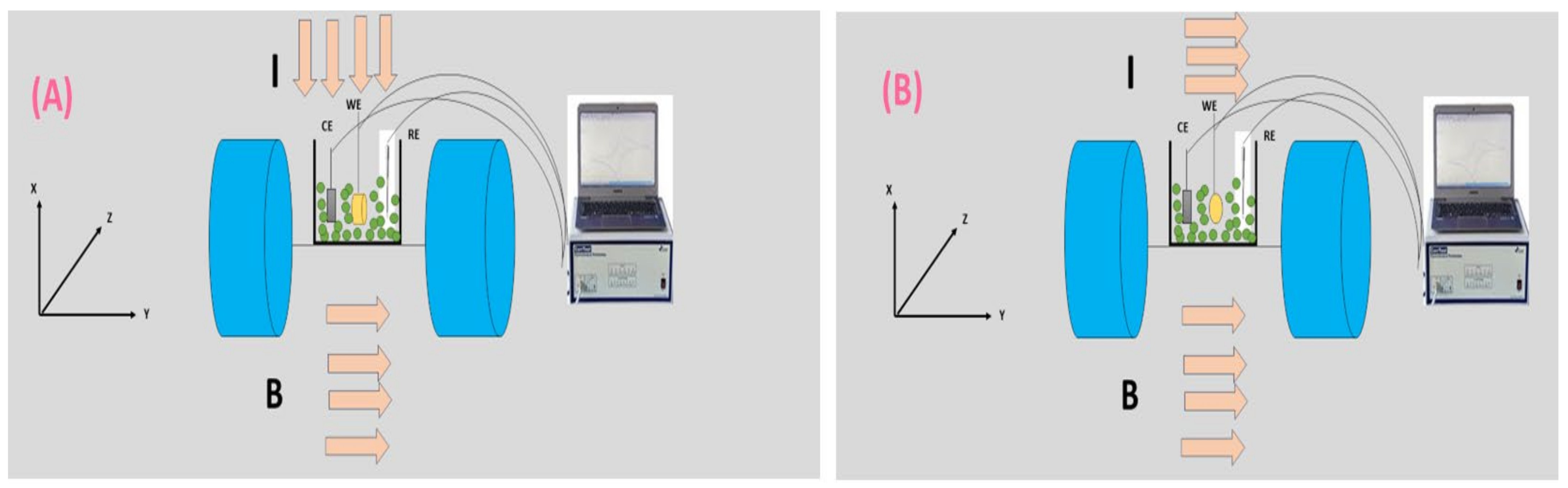
2.2. Preparation of Ni Deposit

The electrochemical deposition process is established in an electrochemical cell with three electrode configurations. The working electrode (WE) is a Cu substrate with a surface area of 2.82 cm2, the counter electrode (CE) is platinum mesh, and the reference electrode (RE) is saturated calomel electrode (SCE). The working electrode is attached to a Teflon holder that isolates the back side and the side face. Further, before each deposition process, WE is chemically polished in a solution consisting of concentrated acids of HNO3, H3PO4, and CH3COOH (1:1:1 Vol ratio) at a temperature of 85 °C for 15 s. The deposition process is performed by using a potentiostat Bio-Logic SAS ModelSP-200 from Pariset, France, for each sample via the chronoamperometric technique for 10 min. The different deposition potentials values are chosen from the cyclic voltammetry of Ni ions from each electrolyte. In the deposition process, an electromagnet (LakeShore Model 642 from Westerville, OH, USA) is utilized to produce a uniform external magnetic field. This magnetic field can be oriented either perpendicular (B, in the x-direction) or parallel (B, in the y-direction) to the electrodes. The magnetic field intensity is 0.5 T. Since the deposited Ni material is ferromagnetic, it becomes magnetized by the external field, leading to local alterations in the magnetic fields near the electrode surface. In addition to the Lorentz force generated by potential surface fluctuations, the magnetic gradient force has the capacity to initiate fluid movement in the vicinity of electrolytes and impact the process of mass transfer. The optimization conditions of the deposition process and the pH for each electrolyte are investigated. Scheme 1 illustrates the electrodeposition process with different orientations of the magnetic field.

2.3. Characterization of Ni Thin Films

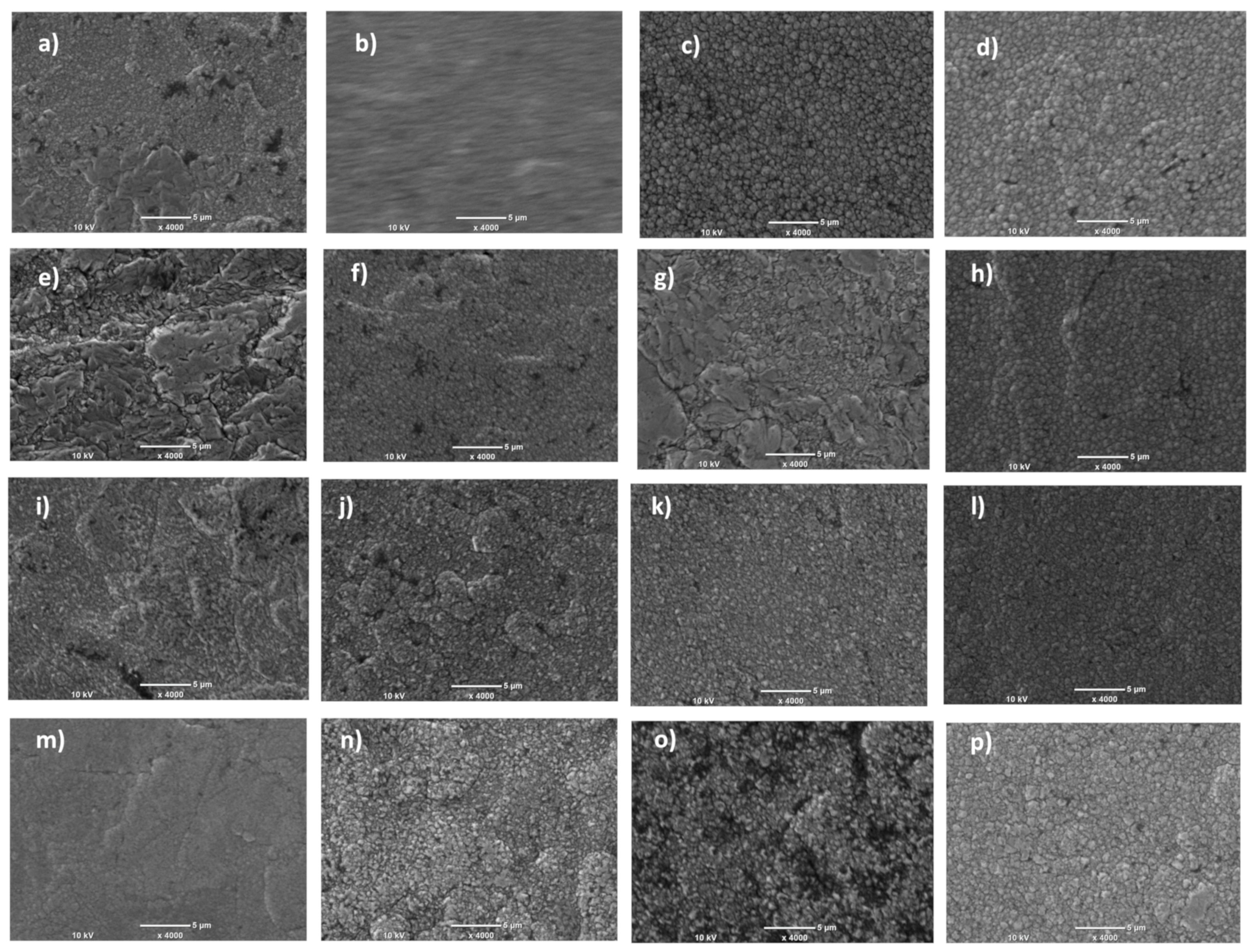
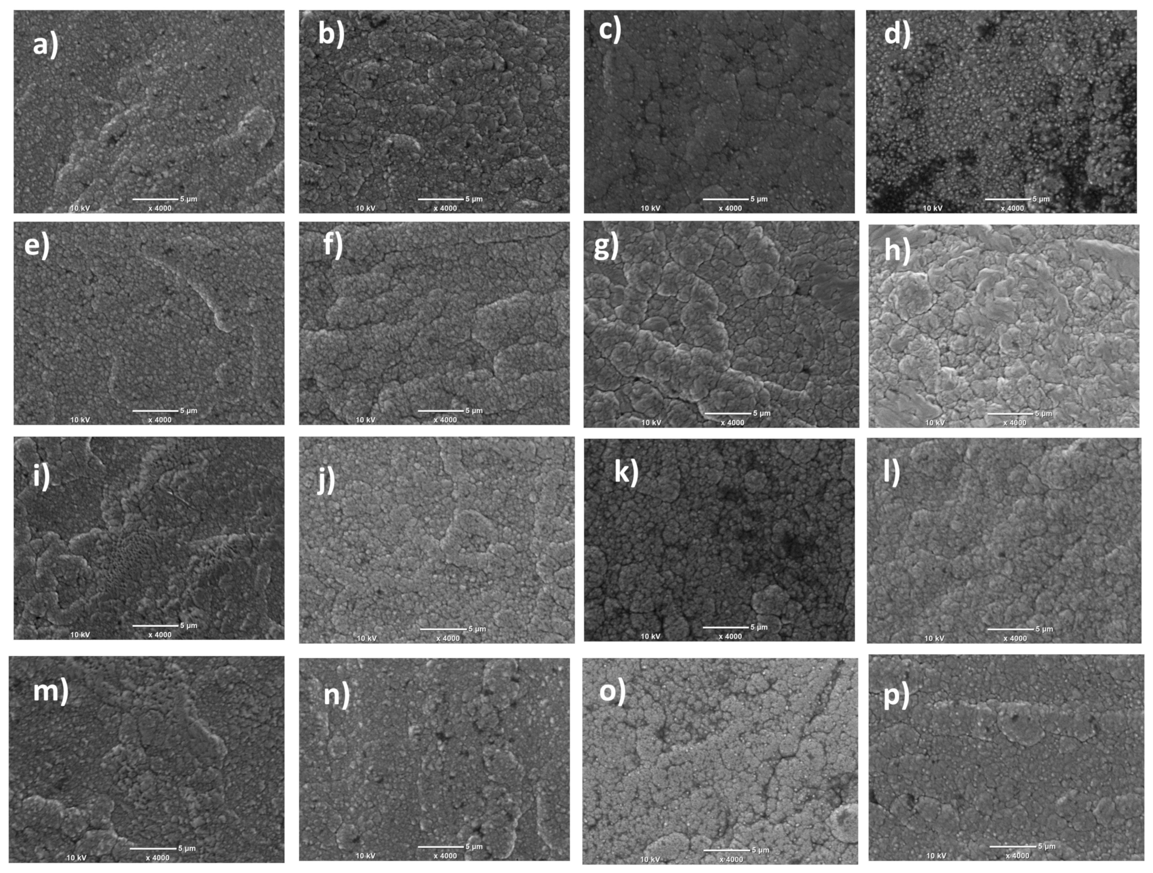
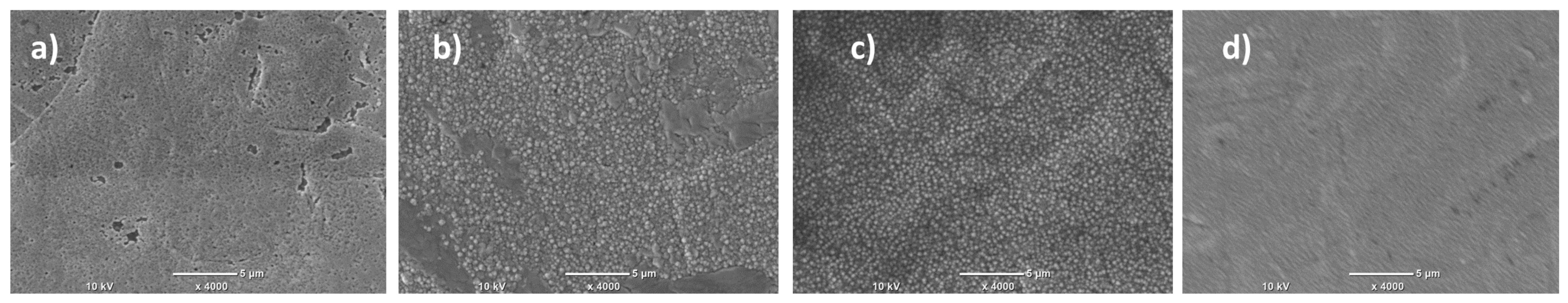
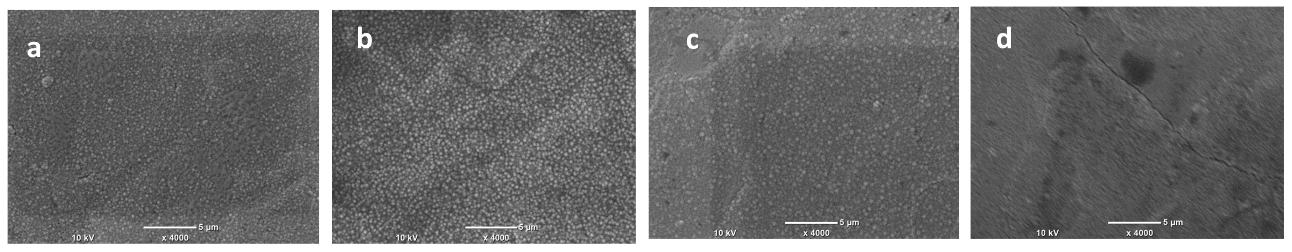
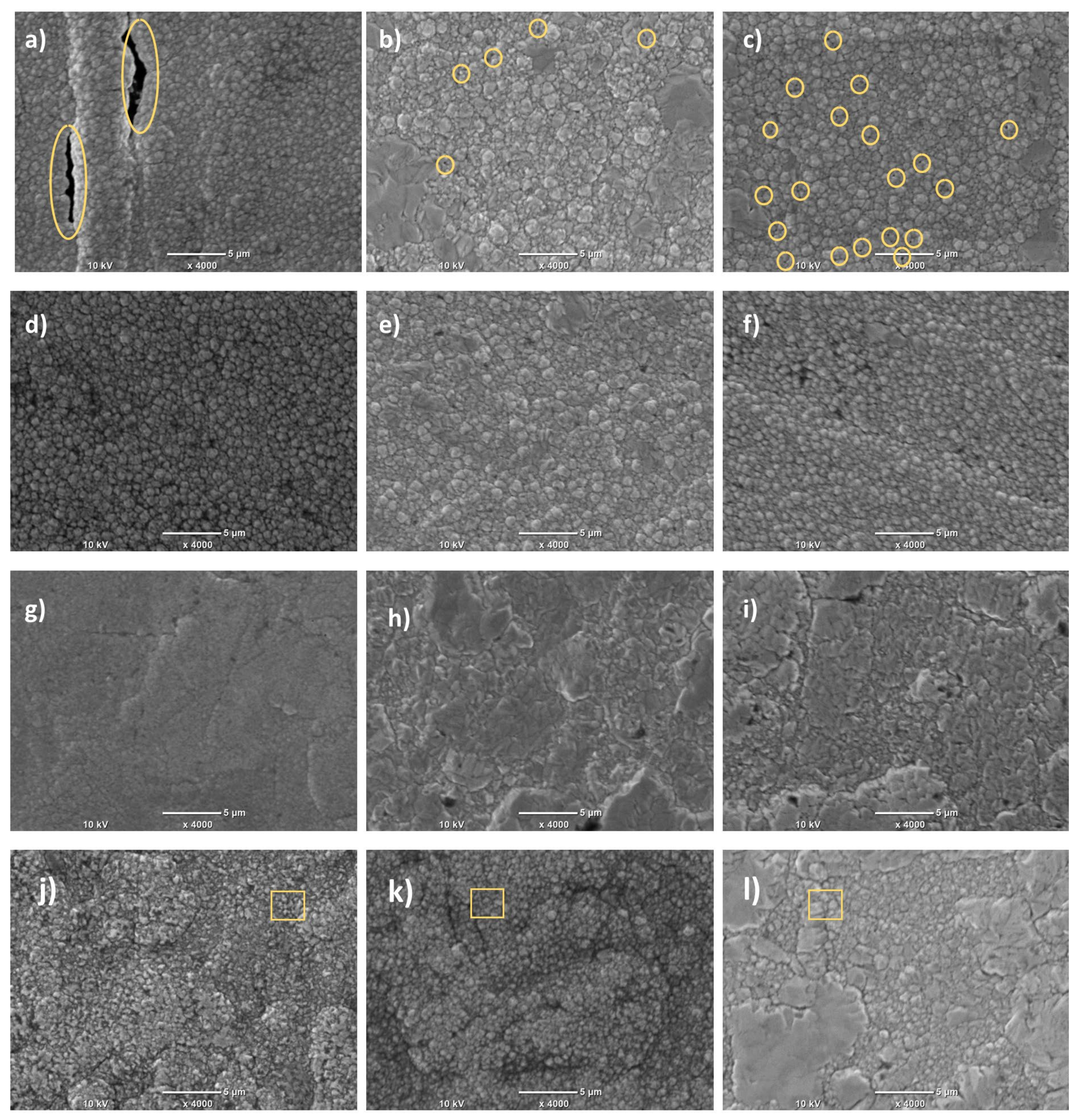
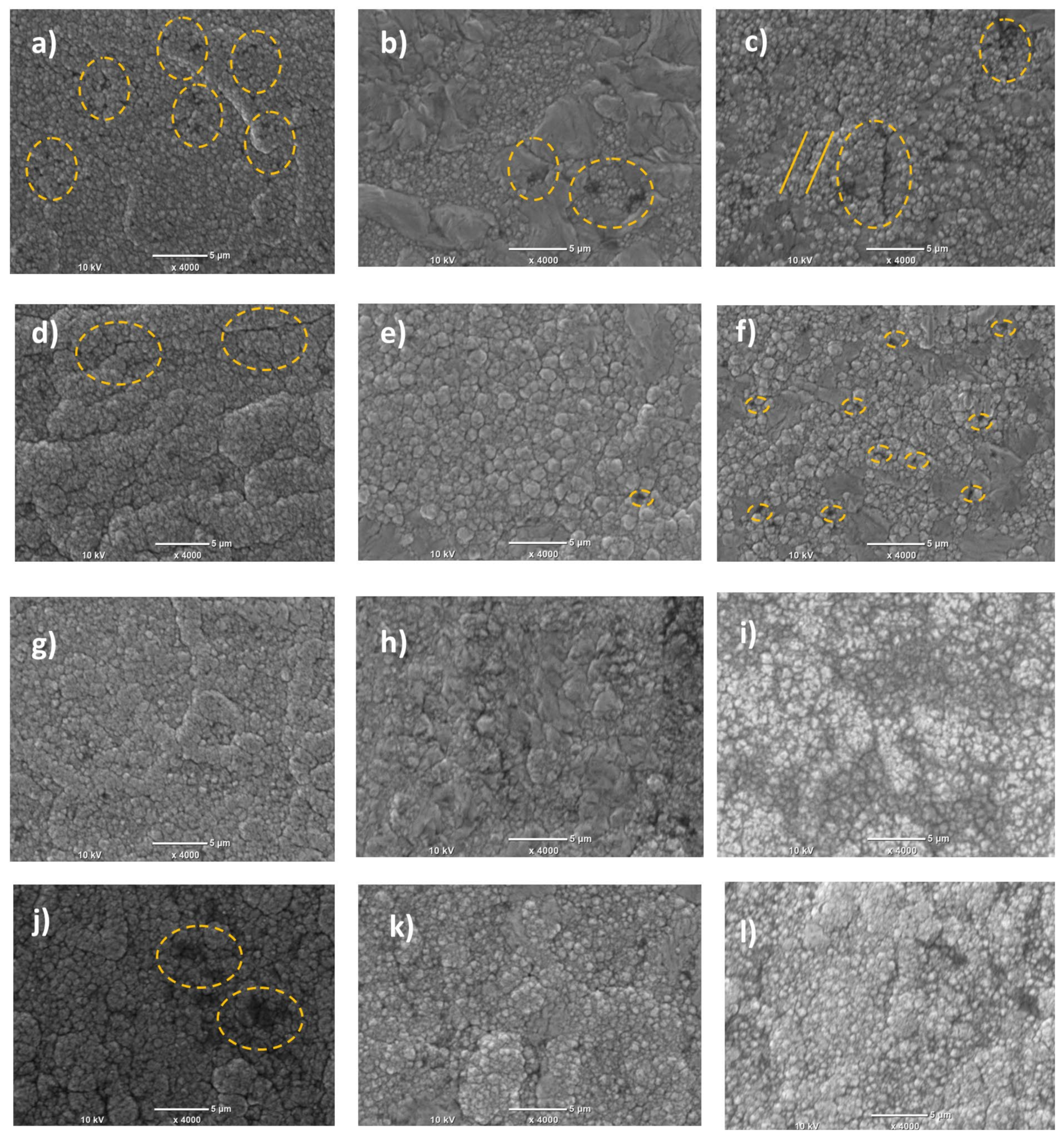
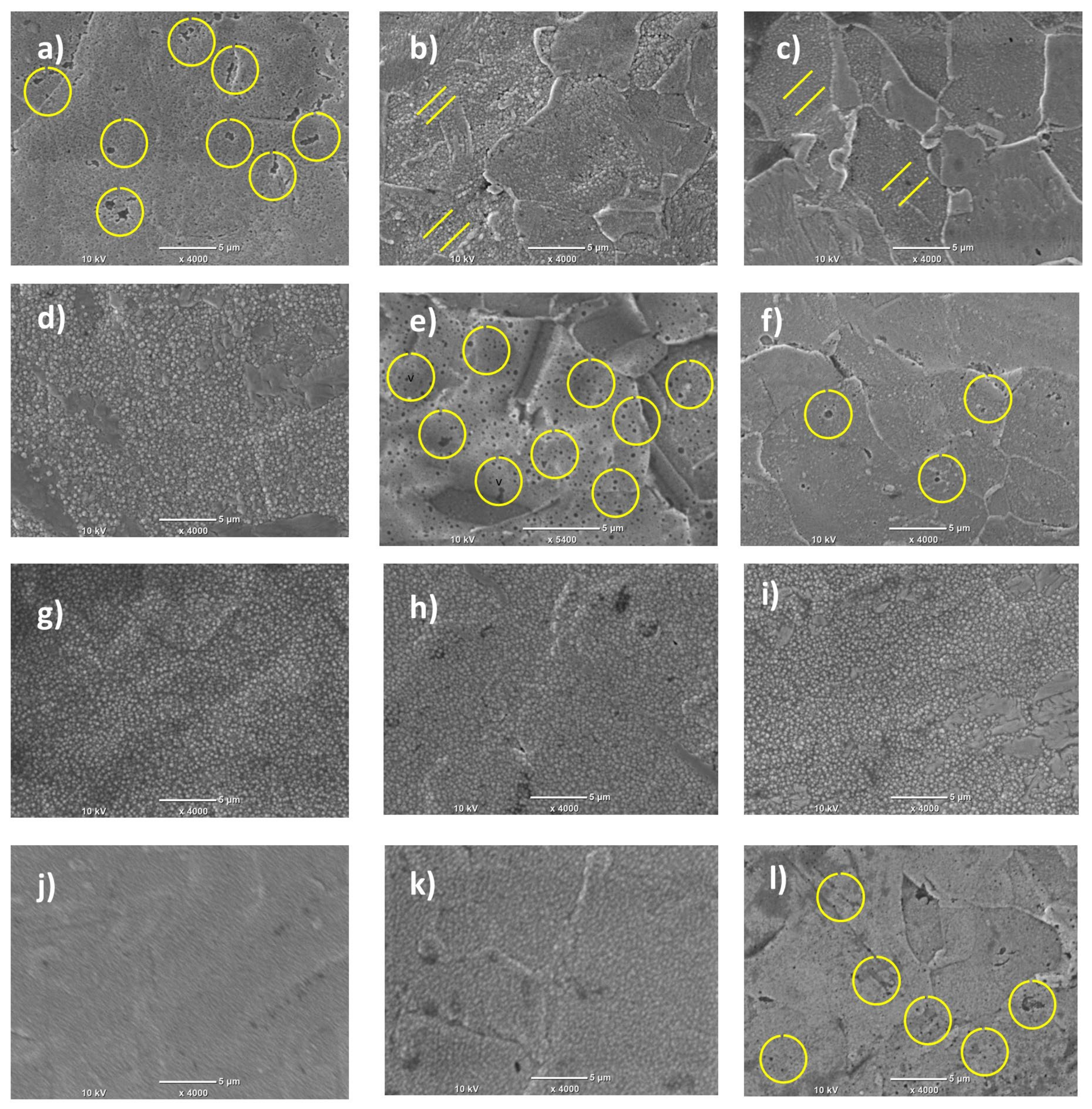
2.3.1. Surface Morphology Study

A scanning electron microscope is used to investigate the surface morphology of the deposits. A Hitachi SU-70 scanning electron microscope (SEM) from Tokyo, Japan is used to examine the surface characteristics of the deposited layers obtained in the experiments.

2.3.2. XRD Analysis

X-ray diffraction is used to characterize the crystallographic structure of the thin films and determine the particle size, which can be calculated by Scherrer equation. X-ray diffraction (XRD) performed with a Rigaku MiniFlex II apparatus from Tokyo, Japan is applied to investigate any potential influence of the applied magnetic field on the crystal structure of the deposits.

2.3.3. Wettability Measurements

Wettability measurements are performed using a high-speed camera Model:9501 with HiBestViewer 1.0.5.1 software. A 10 μL droplet of deionized water is applied to the sample surface, and the contact angle is assessed through contour analysis utilizing Image J software version 2 (GPLv2).

2.4. Electrochemical Studies of Hydrogen Evolution Reaction (HER)

The electrochemical activity of the deposited nickel films is conducted in a conventional three-electrode setup. The synthesized catalysts serve as the working electrode, while a Pt mesh is employed as the counter electrode, and a saturated calomel electrode (SCE) is used as a reference electrode. Linear sweep voltammetry (LSV) measurements are conducted vs. the saturated calomel electrode (SCE) at a scan rate of 5 mV s−1 to investigate the hydrogen evolution reaction (HER) in a solution with a 1 M NaOH concentration. All potential data or overpotentials for the used electrodes are referenced to reversible hydrogen electrode (RHE) and can be computed as follows: Equation (3) [56].
Evs RHE = Evs SCE + E0vs SCE + 0.059 × pH
(E0SCE = 0.33 V)
where Evs SCE is the measured potential for HER in the experiment and E0SCE is the standard redox electrode potential.

3. Results and Discussion

3.1. pH and Potential Optimization of Ni Thin Films Deposited from Acetate Electrolyte

The optimization process of the pH and the deposition potential is accomplished from the acetate electrolyte. The Ni thin films are deposited at different deposition potentials ranges (−1.1 V to −1.4 V) and different pH ranges (1.47, 2.5, 3.7, and 4.4) at room temperature.
Figure 1 shows SEM images of Ni thin films that are fabricated from the acetate electrolyte with a different pH and different deposition potential for 10 min. As noticed from the images, increasing the pH from 1.47 to 4.4 gives different surface morphologies. At a low pH of 1.47, we notice that the surface morphology starts at a low deposition potential of −1.1 V (Figure 1a) to form small particles with ununiform distribution but, by increasing the deposition potential to a more negative potential, the particles become more uniform with a cauliflower structure and are well-distributed at the electrode surface (Figure 1c). By increasing the pH to 2.5, the particles start to form a spherical structure at a high deposition potential of −1.4 V (Figure 1h), while at low deposition potential values, the surface is irregular with flat particles (Figure 1e). Further, by increasing the pH value to 3.7, the surface starts at a low deposition potential value of −1.1 V to have some pores (as seen in Figure 1i), but by scanning the deposition potential to more negative values, the surface becomes rougher, with a hierarchical shape, as seen in Figure 1k,l. Moreover, by further increasing the pH value to 4.4, the surface seems to smooth at a small deposition potential of −1.1 V (Figure 1m), with small fine particles, and then, by increasing the deposition potential to −1.2 V (Figure 1n), it becomes more compact with a hierarchical shape. Further increasing the deposition potential to −1.3 V (as appears in Figure 1o), the surface has some dark areas, which maybe means the presence of some oxides. Therefore, we choose the best surface morphologies for further experiments to study the effect of the magnetic field on their structures and on their catalytic properties towards HER.

3.2. pH and Potential Optimization of Ni Film Deposited from Borate Electrolyte

The optimization process of the pH and deposition potential is established from the borate electrolyte. The Ni thin films are fabricated at different deposition potentials and different pHs than the same values that have been estimated from the acetate electrolyte.
Figure 2 represents the SEM images of Ni thin films deposited from the borate electrolyte with a different pH and a different deposition potential for 10 min by using the chronoamperometric technique. As noticed from the images, increasing the pH from 1.47 to 4.4 introduces different morphologies. From a low pH of 1.47 to a value of 2.5, the surface of the substrate seems smoother and the particle sizes of these layers are smaller than those at higher pH values. When the pH increases, the surface becomes more compact, with larger crystallite sizes. Furthermore, by increasing the deposition potential, the deposits start to have some cracks due to the hydrogen evolution reaction and form some dark areas, leading to the formation of oxides layer, as can be seen in Figure 2d,h,k,o. Therefore, we choose the best surface morphologies for further experiments to study the effect of the magnetic field on their structures and on their catalytic performance towards HER.

3.3. pH Optimization of Ni Thin Film Deposited from Citrate Electrolyte

The same optimization parameters for the pH and deposition potential are chosen for Ni fabricated from the citrate electrolyte as established from the acetate and borate electrolytes.
Figure 3 shows the SEM images of Ni thin films fabricated from the citrate electrolyte at different pHs ranging between (a) 1.47, (b) 2.5, (c) 3.7, and (d) 4.4, respectively, at a constant deposition potential of −1.2 V at room temperature for 10 min using the chronoamperometric technique. Figure 3a represents the SEM image of the deposited Ni thin film at pH 1.47. As noticed, there is an uneven surface full of holes, because, at a low pH, the hydrogen is evolved at the electrode surface, causing pitting of the surface structure. Further, by increasing the pH to 2.5 and 3.7, as indicated in Figure 3b and Figure 3c, respectively, the surface becomes more uniform with well-distributed spherical particles and becomes highly smooth and soft at a higher pH of 4.5, as shown in Figure 3d.

3.4. Electrodeposition Potential Optimization of Ni Thin Films Deposited from Citrate Electrolyte

Figure 4a–d show the SEM images of Ni thin films deposited from the citrate electrolyte at different deposition potentials (−1.1 V, −1.2 V, −1.3 V, and −1.4 V, respectively) at a pH of 3.7 at room temperature for 10 min. Figure 4a represents the SEM image of the deposited Ni thin film at a deposition potential of −1.1 V, which presents that the small spherical particles cover the electrode surface and start to agglomerate to form more uniform particles, well-distributed, and with an organized shape at a potential of −1.2 V (Figure 4b). Further, by increasing the deposition potential to more negative values of −1.3 V and −1.4 V, as seen in Figure 4c and Figure 4d, respectively, the surface becomes much harder with larger particles and the appearance of some cracks at the electrode surface.

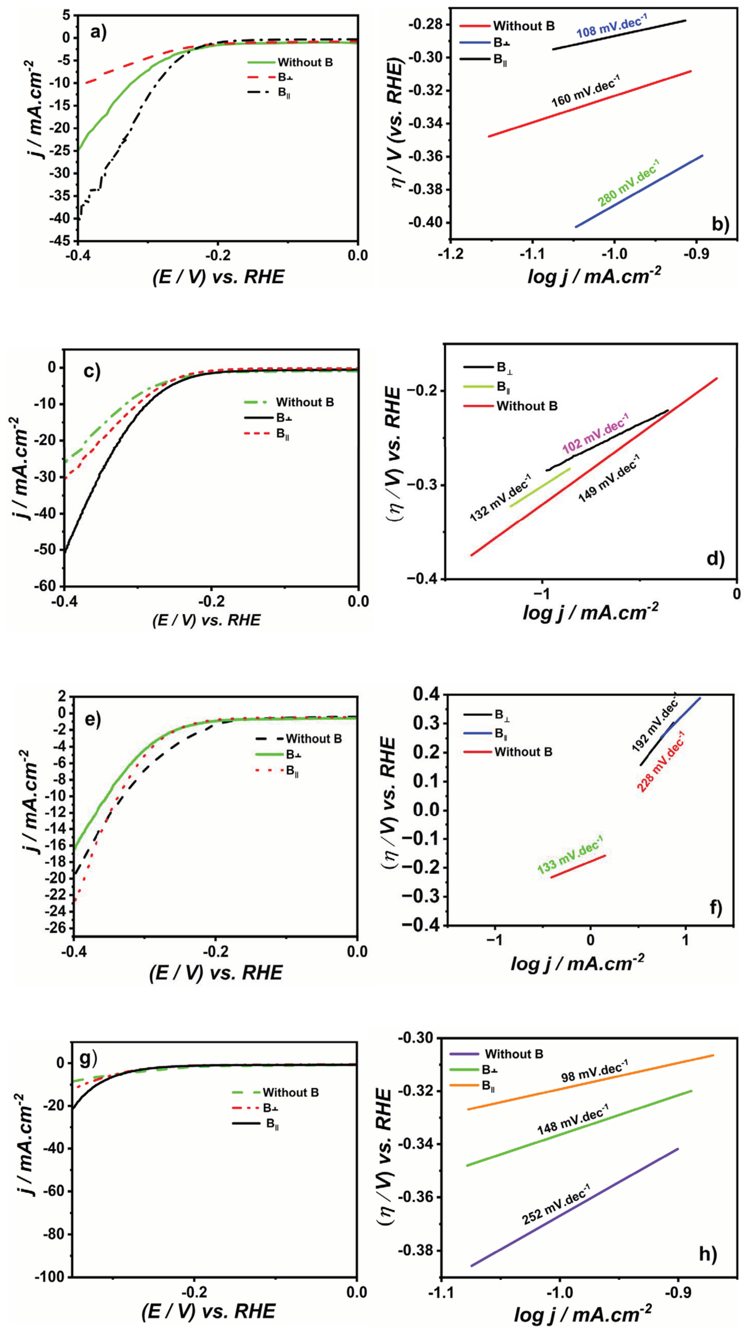
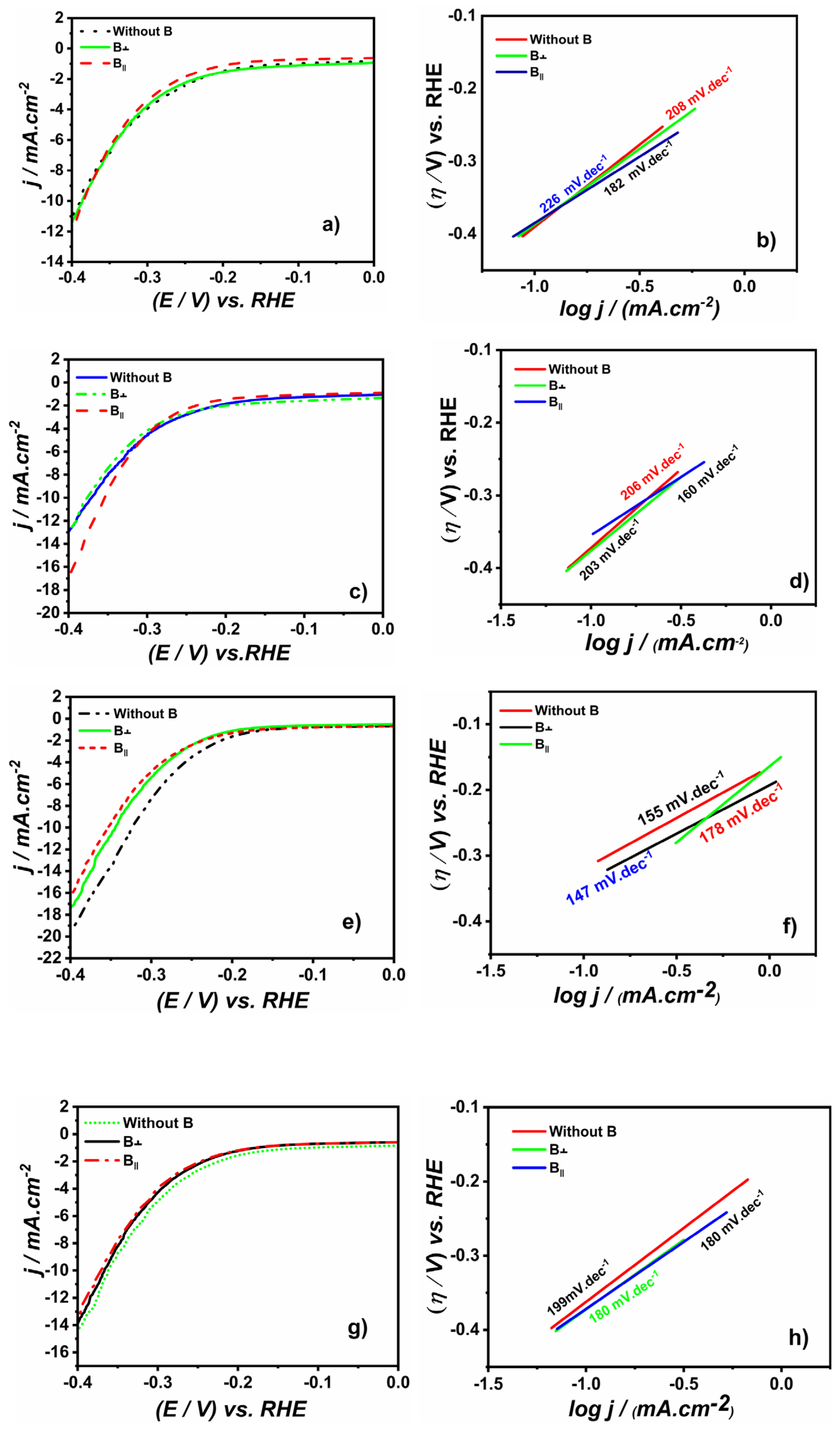
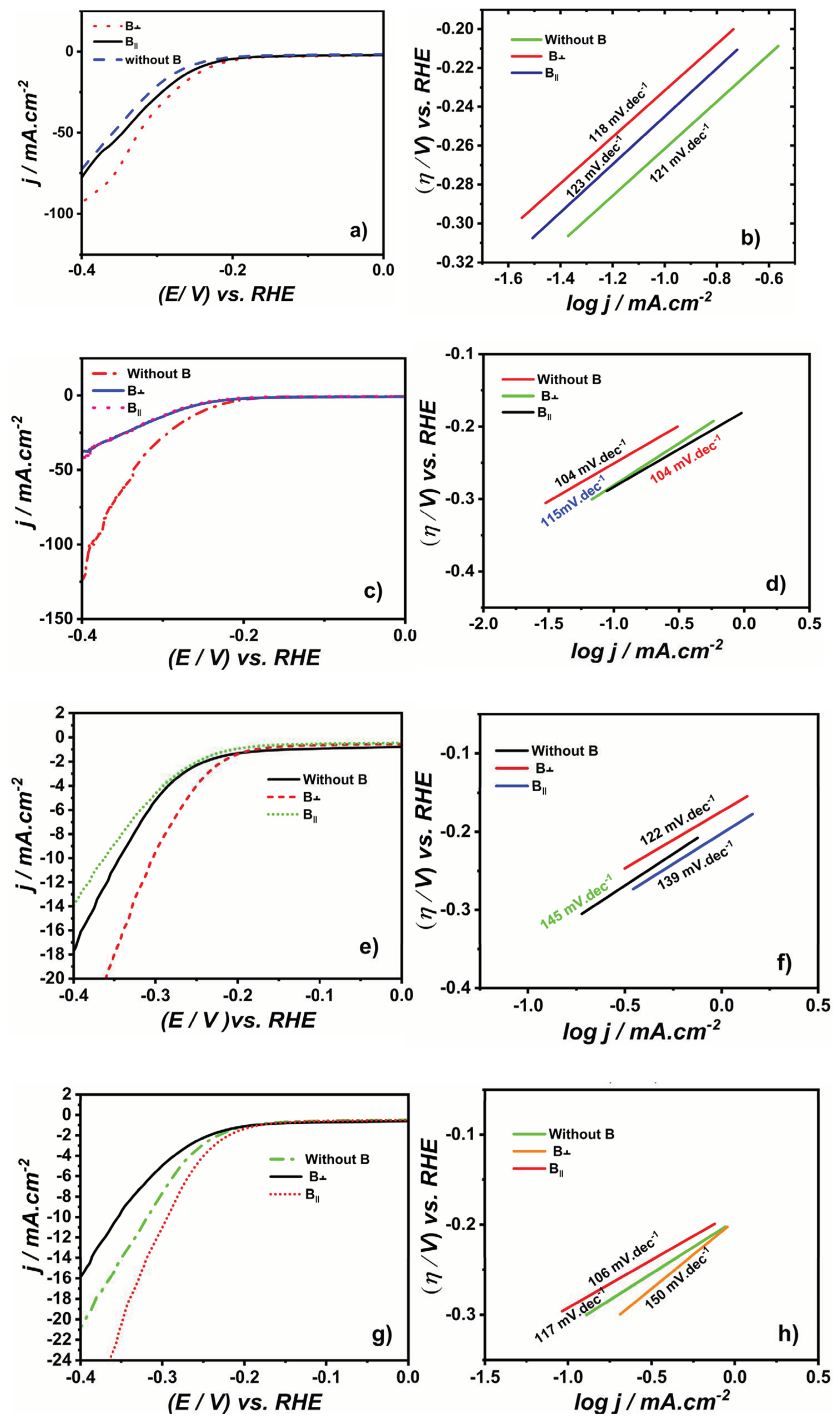
3.5. The Effect of the Magnetic Field on the Electrodeposition of Ni Thin Films from Acetate Electrolyte

We choose the best films after the optimization of pH and the deposition potential for further experiments, for instance, the study of the influence of the magnetic field in both directions perpendicular (B) and parallel (B) to the electrode surface on the morphology changes. Further, we compare the different morphologies in the presence and absence of the magnetic field. Figure 5a–l show the SEM images of the deposited Ni films at pH 2.5 and deposition potential of −1.4 V in the absence of the magnetic field Figure 5a and the presence of the magnetic field in the perpendicular direction (B) (Figure 5b) and parallel (B) (Figure 5c) to the electrode surface. As noticed in Figure 5a, the surface has some voids because of the hydrogen bubbles that evolve during the deposition process. While, as shown in Figure 5b,c, in case of the applied (B) and (B), respectively, the number of holes that appear on the electrode surface decreases in the perpendicular direction, as the residence time of the hydrogen bubbles’ flow at the electrode surface is shorter. Figure 5d,f represent the SEM images of the Ni thin films at pH 1.47 at a deposition potential value of −1.3 V in the absence of the magnetic field (d) and in the presence of the magnetic field in the perpendicular direction (B) (Figure 5e) and the parallel direction (B) (Figure 5f). As shown in Figure 5d, the surface morphology of the electrode surface is completely different in the presence of the magnetic field. The surface seems the same as for conventional nickel coating with large grains and numerous clusters, with some black areas providing the existence of some gaps. On the other hand, after the magnetic field is applied in the case of (B) (Figure 5e), the surface becomes rougher and the coated surface appears flatter. The analysis reveals that certain crystal grains lack complete bonding, resulting in small gaps appearing in the case of (B), as shown in Figure 5f. Figure 5g–l show the SEM images of the deposited Ni films in the absence of B (g) and the presence of (B) (Figure 5h) and (B) (Figure 5i) after their fabrication from the acetate electrolyte at pH 4.4 and a deposition potential of −1.1 V. As noticed, without applying B, the grains agglomerate with small voids at the surface and seem smoother than those obtained with (B) (Figure 5h) and (B) (Figure 5i), where the surface appears rougher and more compact. Yet, in Figure 5j–l (that present the SEM images of the fabricated Ni films in the absence of B (j) and the presence of (B) (Figure 5k) and (B) (Figure 5l) after their fabrication from acetate electrolyte at pH 4.4 at a deposition potential of −1.2 V), the agglomeration of the particles increases at a higher deposition potential, forming a hierarchical structure, as shown in Figure 5j. However, with the application of (B) (Figure 5k), the sharpness of the hierarchical structure starts to be reduced and the surface becomes a little bit smoother. Yet, in the case of (B) (Figure 5l), the particles become flatter, with larger sizes.

3.6. The Effect of the Magnetic Field on the Electrodeposition of Ni Thin Films from Borate Electrolyte

We choose the best samples that are deposited from the borate electrolyte after the pH and deposition potential optimization process for studying the impact of the magnetic field (B) in different directions to the electrode surface (B) and (B) on the surface morphology. Figure 6a–l describe the various morphologies of Ni thin films under the influence of the magnetic field and without it. Figure 6a–c represent the fabricated films from pH 1.47 at a deposition potential of −1.1 V in the absence of (B) and presence of (B) and (B), respectively. As seen, some holes appear on the surface because of the hydrogen gas, while in the case of the deposition in the presence of (B), the particles agglomerate in small bulges and sheets, reducing these holes. On the other hand, in the case of applied (B), the holes appear again and some cracks are shown at the surface. Figure 6d–f represent the deposited layers of Ni films from pH 1.47 at a deposition potential of −1.2 V in the absence of (B) and presence of (B) and (B), respectively. As seen, by increasing the deposition potential, the particle bulge sizes increase in the case of (B) and the gaps have almost disappeared. Yet, in the case of the absence of B and (B), there are some cracks and gaps between the particles. On the other hand, by increasing the pH to 2.5 and the deposition potential of −1.2 V, we notice the different morphologies of the fabricated films, as seen in Figure 6g–i in the absence of (B) and presence of (B) and (B), respectively. The absence of B represents Ni films with small spherical particles, while in the case of (B), the particles start to form a hierarchical structure and the borders between these hierarchical structures become sharper in the case of (B). On the contrast, in the case of increasing the pH to 3.7 at the same deposition potential of −1.2 V, as seen in Figure 6j–l, in the absence of (B) and presence of (B) and (B), respectively, the morphologies of the surfaces in both (B) and (B) are almost the same, with small dark areas appearing in the case of (B), and the surface seems to be rougher.

3.7. The Effect of the Magnetic Field on the Electrodeposition of Ni Thin Films from Citrate Electrolyte

The SEM images of coated Ni thin films are shown in Figure 7a–l in the absence of B and presence of (B) and (B) at different pH ranges from 1.47 to 4.4 at the same deposition potential value of −1.2 V. These pH values and the deposition potential are chosen depending on the optimization process that is accomplished with different pH and different potential values. As indicated in Figure 7a–l, at a low pH of 1.47, the surface is full of holes due to the evolution of hydrogen gas in the absence of (B) (Figure 7a), and with applied (B) (Figure 7b) and (B) (Figure 7c), the surface is uneven with less holes and fine and small particles because of the influence of the magnetic field that reduces the existence of the hydrogen bubbles on the electrode surface; in the case of (B), the particles become flatter. On the other hand, by increasing the pH to 2.5, the surface becomes more uniform with spherical particles due to the trisodium citrate that is working as a complexing agent and reducing the overpotential of the hydrogen evolution (Figure 7d), but in the case of applied (B), the surface becomes smoother but with the appearance of many holes (Figure 7e) and the SEM result in applied (B) is almost the same, with small holes found at the electrode surface (Figure 7f). However, by increasing the pH to 3.7 (Figure 7g–i), there is almost no difference in the three cases, but the surface becomes more compact and the particles are well-distributed at the surface. With a further increase in the pH to 4.4, the surface becomes smoother but, in the case of (B) (Figure 7l), the holes appear again at the electrode surface.

The Relation between Changing the pH Value and the Applied Magnetic Field

During the deposition process from the aqueous electrolytes with a negative standard potential for the deposited metal, there is a possibility of additional side reactions occurring. Common reactions that can occur during the deposition of metals from the Fe group include:
Mn+ + ne ↔ M
2H+ +2 e ↔ H2
2H2O + 2e ↔ H2 + OH
xMn+ + xH2O↔ Mx(OH)y(xn−y)+ + yH+
Mx(OH)y(xn−y)+ + (xn − y) H2O ↔ M(OH)n + (xn − y)H+
Reaction (5), known as the hydrogen evolution reaction (HER), leads to the consumption of H+ ions, resulting in an elevated pH near to the electrode surface. When the applied potential is sufficiently high, water decomposition (6) can take place, generating OH ions, further increasing the pH near to the electrode. In cases where the pH becomes sufficiently high, additional reactions may occur, creating a buffering effect, such as the hydrolysis of metal ions (7), which generates H+ ions and lowers the pH values. If Reaction (7) cannot effectively counteract this, further changes may occur, for example, increasing the pH and precipitation of hydroxides (8) that can be found as contaminants within the deposit [57]. When a magnetic field is introduced during the deposition process, it triggers additional effects, primarily the magnetohydrodynamic (MHD) effect driven by the Lorentz force. This MHD effect boosts the movement of substances within the electrolyte solution, leading to higher deposition rates and constraining current densities for reactions controlled by mass transport. Studies have shown that the application of a magnetic field in the perpendicular direction during the electrodeposition of transition metals results in a decrease in the pH value near to the electrode, leading to an enhancement in the quality of the deposited cobalt. However, in cases of the application of the magnetic field in the parallel direction, the induced convection is not enough to lower the pH value near to the electrode surface. Generally, the increase in the pH value near to the electrode surface in cases of the absence of the magnetic field is much higher than using the magnetic field and this will affect the deposit’s morphology and its characteristics [57,58,59,60,61].

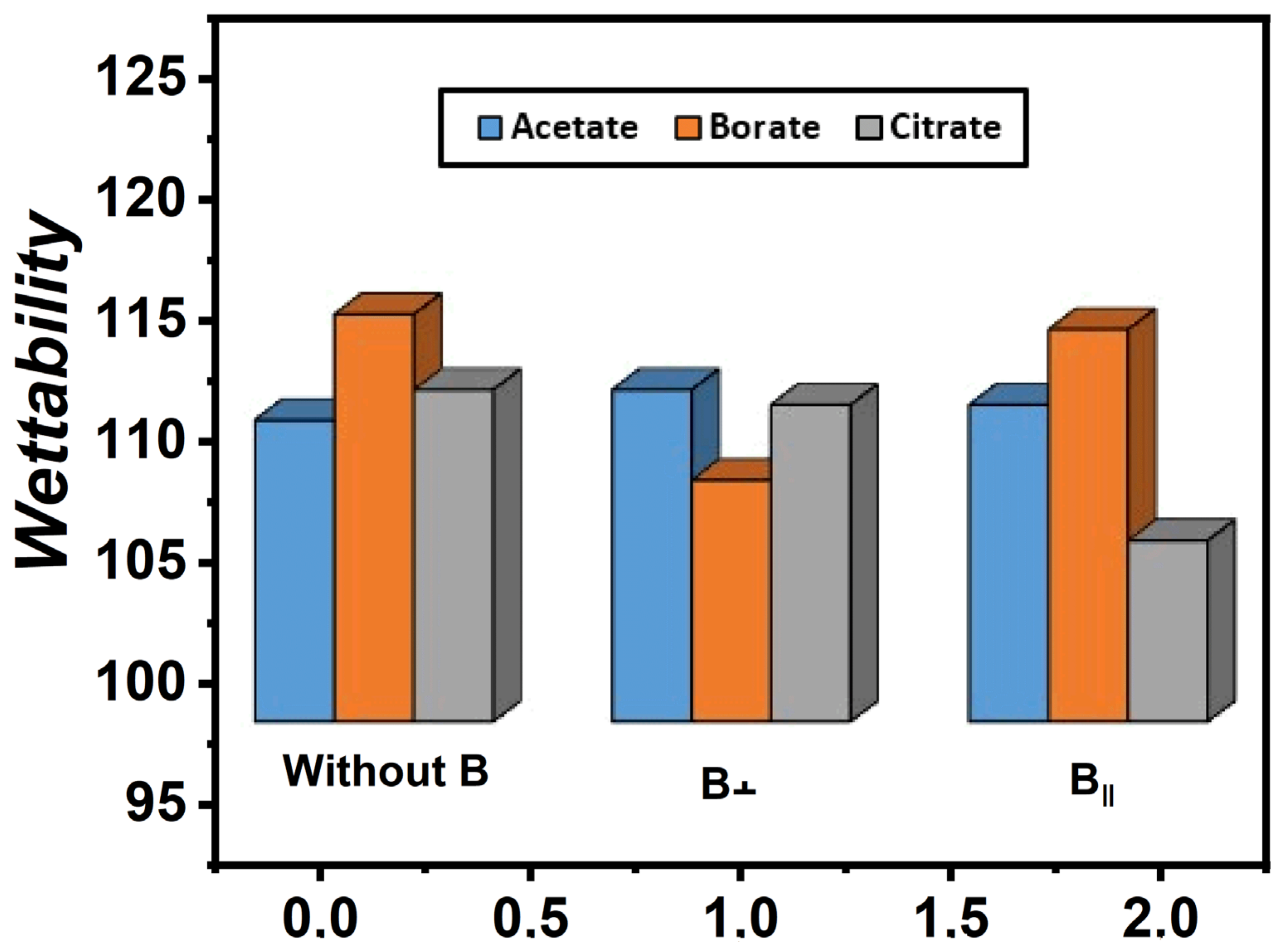
3.8. Wettability Study of the Fabricated Ni Thin Films Surfaces
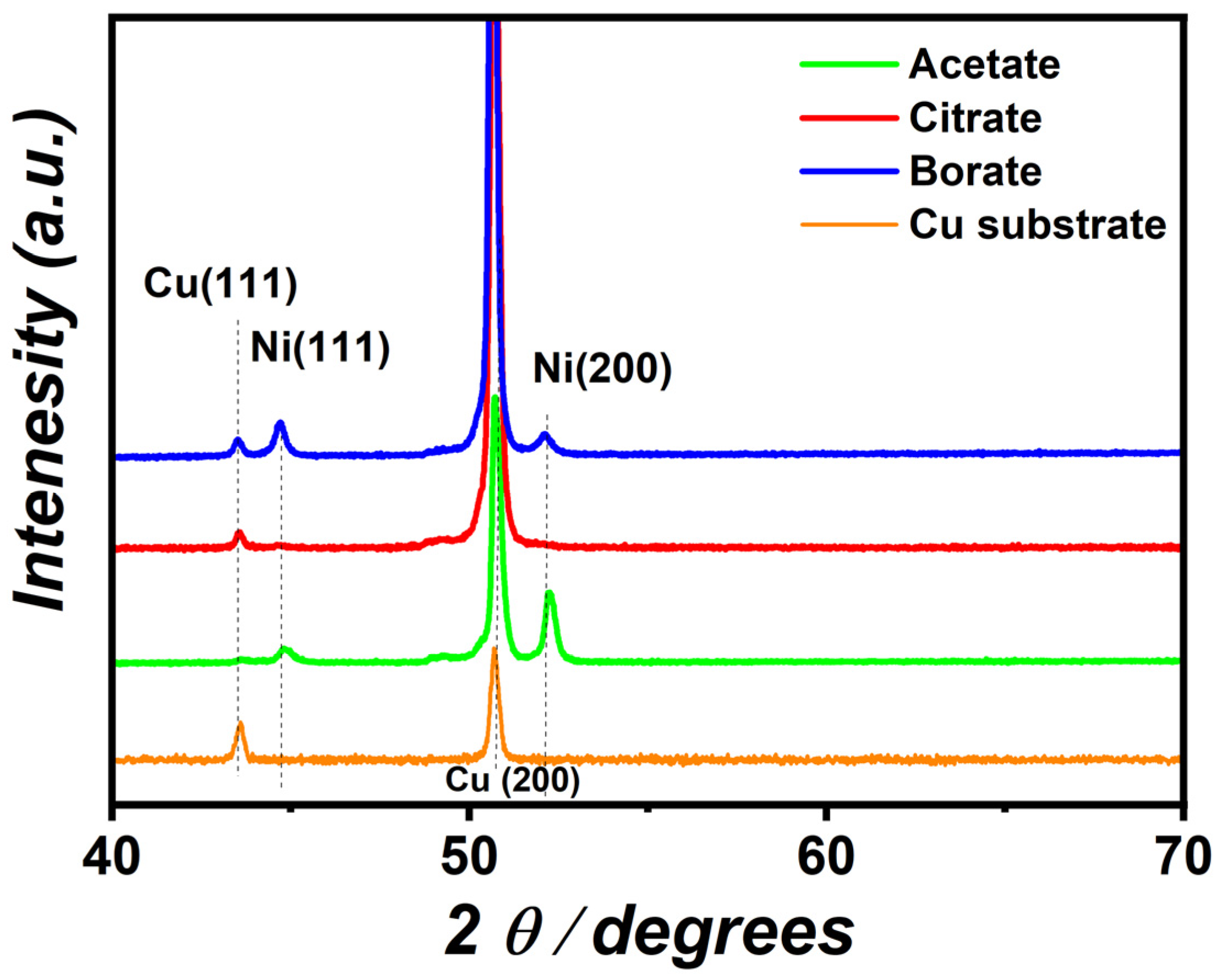
The surface wetting properties of the electrode are examined using water contact angle measurements, where a water droplet is used as the liquid sample. Figure 8 represents the chart that describes the difference in the contact angle values of each Ni thin film that is obtained from the acetate, the borate, and the citrate electrolyte at pH 2.5 in cases of the deposition without application of the magnetic field and in cases of the application of the magnetic field in perpendicular and parallel directions to the electrode surface. As seen, the contact angles of all Ni thin films are bigger than 90°, which means that all the surfaces are hydrophobic in all cases from the three electrolytes and even in the absence and existence of the magnetic field. As noticed, in cases of the electrodeposition from the acetate electrolyte, the contact angle of the fabricated Ni becomes high in cases of the applied magnetic field in the perpendicular direction to the electrode surface (B), while the contact angle for the Ni surface obtained from the citrate and the borate at the same pH becomes the highest value in the absence of the magnetic field, suggesting that the composition of the electrolyte species plays an essential role in the hydrophobic properties and changes the morphology of the formed surface in cases of the presence or absence of the magnetic field.

3.9. XRD Analysis

XRD analysis is accomplished on the fabricated Ni obtained from the three different electrolytes that give the highest electrocatalytic performance to HER. Based on that, we choose the best three samples from the three electrolytes. Figure 9 represents XRD that was made for the Ni thin films obtained from the citrate at pH 1.47 at a deposition potential of −1.2 V in the presence of B to the electrode surface, the borate electrolyte at pH 2.5 in the absence of B, and the acetate electrolyte at pH 2.5 at a deposition potential of −1.4 V in the presence of B to the electrode surface. The XRD experiment shows that the bar Cu substrate possesses two diffraction peaks at 2θ values of 43.5° and 50.69° that refer to the diffraction planes (111) and (200) according to JCDPS card no. 00-001-1242. The deposited Ni from the acetate shows two diffraction peaks for face-centered cubic Ni (FCC) at 2θ values of 44.8° and 52.23° that refer to diffraction planes (111) and (200) according to JCDPS card no. 01-077-8461. Further, the analysis provides that, for the deposited Ni from the borate, two diffraction peaks are found at 2θ values of 44.6° and 52.07° that refer to diffraction planes (111) and (200) according to JCDPS card no. 01-078-7536, which indicates that the same crystalline phases are also formed for the fabricated Ni from the borate. However, for the Ni film deposited from the citrate, no remarkable peaks appear, except two peaks for the Cu substrate, because the thickness of this film is too thin (it is calculated at 0.179 μm, indicating a strong signal from the substrate), while the thickness of the films deposited from the acetate and borate are 5.8 and 2.7 µm. The crystallite size is calculated for Ni deposits from the acetate and borate from their distinct peaks using Scherer Equation (4) [62]. The average crystallite size for the deposited Ni from the acetate and borate is found to be 20.16 and 14.11 nm, respectively.
D = Kλ/βcos θ
where D represents the crystallite size in nm, K (0.9) is the Scherrer constant, λ is the wavelength of incident X-ray (0.15406 nm), and β represents the radian value of width at the half-height of the peak.

3.10. Electrocatalytic Activity of Ni Thin Films from Acetate towards HER and Its Relation with the Contact Angle

Figure 10a,b represent the linear sweep voltammetry (LSV) curves in 1 M NaOH for HER at a scan rate of 5 mV s−1 and their Tafel plots, respectively, for the deposited Ni thin films from acetate at pH 1.47 and a deposition potential of −1.3 V in the presence and absence of the magnetic field (B). It is found that the Ni thin film that is fabricated under the magnetic field in parallel direction B has the highest contact angle and more hydrophobic properties for this surface, which produces the smallest overpotential value of 280 mV to achieve a current density of 10 mA·cm−2 towards HER and a Tafel slope value of 108 mV·dec−1 with the highest contact angle value of 117.36, while both Ni thin films that are fabricated without B and under B give higher overpotential values of 323 mV and 379 mV, respectively, and contact angle values of 116.19 and 114.37, which means that the highest contact angle between them gives the lowest overpotential value and hence higher catalytic activity. However, by increasing the pH to 2.5 at a deposition potential of −1.4 V (Figure 10c,d), the fabricated Ni thin film in the case of applied (B) gives the lowest overpotential value of 287 mV·s−1 to achieve the current density of 10 mA·cm−2 towards HER, with a smaller Tafel slope value of 102 mV·dec−1 compared with the Ni thin film obtained at a lower pH value of 1.47 in the case of B, while the contact angle remains at almost the same value of 117.38. On the other hand, while increasing the pH to 4.4 at a deposition potential of −1.1 V (Figure 10e,f), the contact angle becomes larger (119.01) in the case of the absence of B than in that obtained under the influence of (B) and B, even though the overpotential value becomes 325 mV to reach a current density of 10 mA·cm−2 towards HER and is higher than that obtained for Ni films fabricated under the effect of B, while the Tafel slope becomes the smallest value, at 133 mV·dec−1. Moreover, by increasing the deposition potential to −1.2 V, it gives the smallest value of 325 mV for the overpotential for HER in the case of Ni thin film obtained by applied B with the smallest Tafel slope value of 98 mV·dec−1. From these results, we can conclude that the magnetic field influences the catalytic properties of the thin films obtained and the hydrophobic character of the film. All the thin films obtained are with hydrophobic properties, but we can see that the electrolyte pH plays an important role in changing the contact angle value and the catalytic properties towards HER. The different values of η, the Tafel slopes, and the contact angles related to each Ni thin film obtained in the absence and presence of the MF are shown in Tables S1–S4.

3.11. Electrocatalytic Activity of Ni Thin Films from Borate towards HER and Its Relation with Wettability Measurements

Figure 11a,b present the LSV curves in 1 M NaOH for HER at a scan rate of 5 mV s−1 and their Tafel plots, respectively, for the deposited Ni thin films from the borate electrolyte at pH 1.47 and a deposition potential of −1.1 V in the presence and absence of the magnetic field. It is noticed that the Ni thin film fabricated under the magnetic field in the parallel direction to the electrode surface B has the highest contact angle value of 116.34, which means there are more hydrophobic properties for this surface, which gives the smallest overpotential value of 380 mV to achieve a current density of 10 mA·cm−2 towards HER and the lowest Tafel slope value of 204 mV·dec−1, while both Ni thin films that are fabricated without B and under B give higher overpotential values of 391 and 384, respectively, and contact angle values of 114.18 and 115.52, which means that the highest contact angle between them produces the lowest overpotential value and hence higher catalytic activity towards HER. Yet, by increasing the deposition potential to −1.2 V for the same pH 1.47, the contact angle increases to 116.9 for the Ni thin film fabricated under the magnetic field in the parallel direction to the electrode surface B, and the polarization curve for HER gives a smaller value for the overpotential 367 mV to achieve a current density of 10 mA·cm−2 and a smaller Tafel slope value of 160 mV·dec−1, as seen in Figure 11c,d, compared with the values obtained for Ni thin film fabricated under the magnetic field in the parallel direction B, which is deposited at a lower deposition potential of −1.1 V that gives a value of 182 mV·dec−1 for the Tafel slope. However, by increasing the pH value to 2.5 and the deposition potential to −1.2 V (as indicated in Figure 11e,f), the polarization curves show the smallest overpotential value of 318 mV and the smallest Tafel slope value of 155 mV·dec−1 for the Ni thin film obtained in the case of the absence of the magnetic field with the highest contact angle value compared with the values obtained for both Ni thin films, which are fabricated under the influence of B and under B that give higher overpotential values of 342 and 354, respectively, and contact angle values of 115.39 and 111.06. By increasing the pH to 3.7 and the deposition potential to −1.2 V, the value of the overpotential to reach a current density of 10 mA·cm−2 is 358, 360, and 373 mV for Ni thin films obtained in the absence of B, B, and B, respectively. It is noticed that these values are higher than those obtained at a lower pH; however, the smallest value for the overpotential for HER is for Ni thin film fabricated without B compared with those values obtained under the influence of the magnetic field. From these results, we can conclude that, in the borate electrolyte, the pH plays a vital role in the formation of morphological structures and the catalytic activity for HER [63,64,65], and the wettability of the surface is changed, depending on the use of the magnetic field or not. It is noticed that the magnetic field with the parallel direction at a lower pH produces Ni thin films with the highest catalytic performance towards HER because of the increase in the contact angle of the surface, which means that the hydrogen bubbles are rapidly separated due to the short time residue. On the other hand, by increasing the pH, the Ni thin films obtained under the influence of the magnetic field have smaller contact angles, and hence catalytic activity, towards HER, which is decreased due to the long time residue for the hydrogen bubbles at the surface that block the active sites of the deposits. The different values of η, Tafel slopes, and contact angles related to each Ni thin film obtained in the absence and presence of the magnetic field can be seen in Tables S5–S8.

3.12. Electrocatalytic Activity of Ni Thin Films from Citrate towards HER and Its Relation with Wettability Measurements

Figure 12a–f represent the cathodic polarization curves of different fabricated Ni thin films from the citrate electrolyte at different pHs (1.47, 2.5, 3.7, and 4.4) in the presence and absence of the magnetic field in 1 M NaOH at a scan rate of 5 mV·s−1. It is noticed that the Ni thin films that are deposited at a low pH of 1.47 give the lowest overpotential value of 231 mV to reach a current density of 10 mA·cm−2 in the case of the deposition under the magnetic field in the perpendicular direction (B) to the electrode surface because it has the highest contact angle and thus the shorter residual time for the hydrogen bubbles to be on the surface. However, by increasing the pH to 2.5, the Ni thin films obtained under the influence of the magnetic field are not affected to be better than those obtained in the absence of the magnetic field. We notice that the contact angle becomes the highest value for the Ni thin film obtained in the absence of the magnetic field and it has the lowest overpotential value of 245 mV to reach a current density of 10 mA·cm−2 and the smallest Tafel slope value of 104 mV·dec−1, which means higher catalytic activity towards HER. On the other hand, by increasing the pH to 3.7, the fabricated Ni thin films obtained under the magnetic field in the perpendicular direction (B) to the electrode surface give the smallest overpotential value of 304 mV to achieve a current density of 10 mA·cm−2 and the smallest Tafel slope value of 122 mV·dec−1, which has the highest contact angle of 115.05. Moreover, by further increasing the pH value to 4.4, the Ni thin film obtained in the case of the application of the magnetic field in the parallel direction to the electrode surface (B) has the highest contact angle value of 115.70 and hence gives the smallest overpotential value of 294 mV for reaching a current density of 10 mA·cm−2 and the smallest Tafel slope value of 106 mV·dec−1, which indicates that this electrode has higher catalytic performance towards HER compared with the other Ni thin film electrodes with small contact angles. The different values of η, Tafel slopes, and contact angles related to each Ni thin film obtained in the absence and presence of the B are shown in Tables S9–S12.

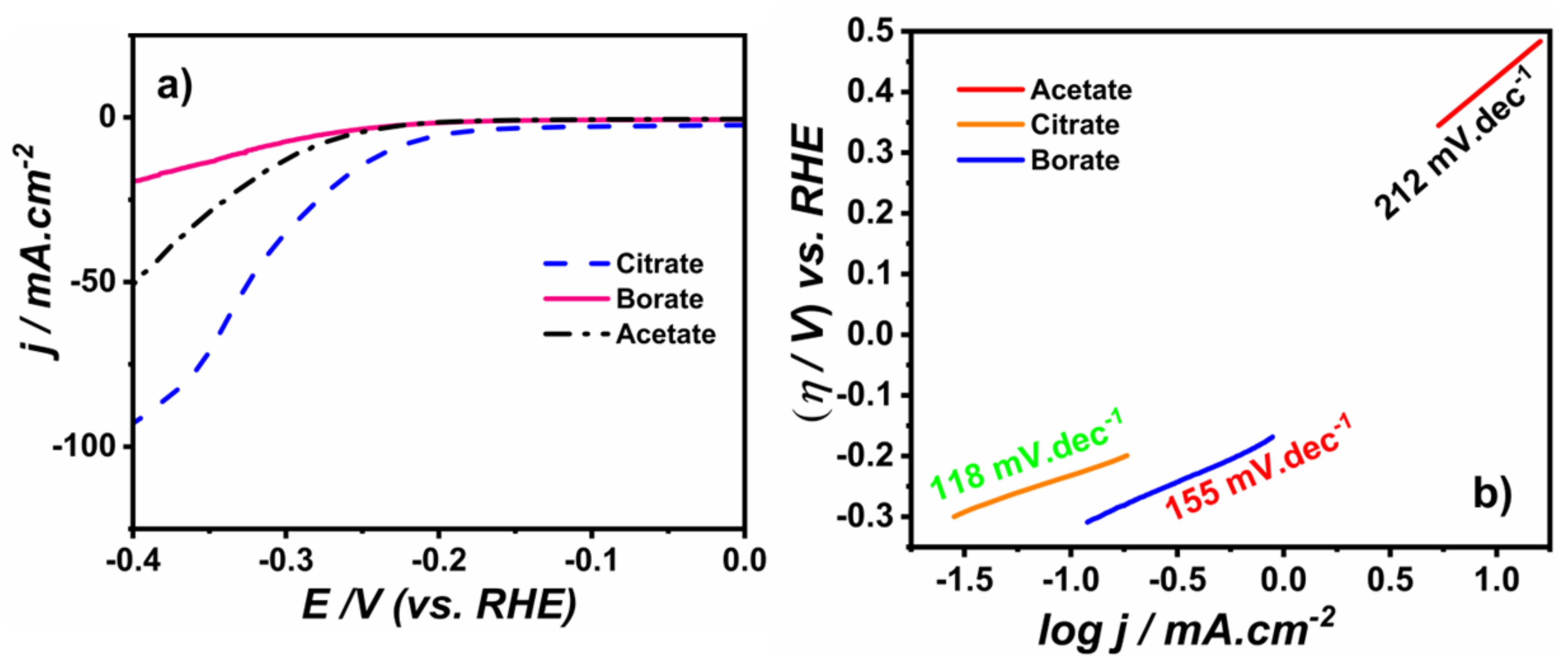
3.13. The Comparison between the Electrocatalytic Activity towards HER from the Three Different Electrolytes

We choose from the above optimization parameters the best samples from each electrolyte that give us the lowest overpotential value and the highest catalytic performance towards HER in order to compare the three different electrolytes’ effects on the electrodeposition of Ni thin films and hence their catalytic performance.
Figure 13a illustrates the cathodic polarization curves of Ni-fabricated electrodes produced under different conditions. The first set is obtained using a citrate electrolyte with a pH of 1.47 and a deposition potential of −1.2 V in the presence of B to the electrode surface. The second set uses a borate electrolyte with a pH of 2.5 without B, and the third set utilizes an acetate electrolyte with a pH of 2.5 and a deposition potential of −1.4 V in the presence of B to the electrode surface. These experiments are conducted in a 1 M NaOH solution with a scan rate of 5 mV s−1. Interestingly, the Ni thin film obtained from the citrate electrolyte with B shows the most favorable results. It displays the lowest overpotential value and the highest catalytic activity among the three electrode types. Specifically, at a current density of 10 mA cm−2, this Ni thin film exhibits an overpotential (η) of 231 mV compared with the reference hydrogen electrode (RHE). On the other hand, the Ni thin film produced from the borate electrolyte requires an overpotential of 319 mV to achieve the same current density, while the Ni fabricated from the acetate electrolyte needs an overpotential of 291 mV to reach 10 mA cm−2. Consequently, the Ni thin film generated from the citrate electrolyte with B demonstrates superior catalytic activity compared with the other Ni electrodes produced from the acetate and borate electrolytes in the context of the hydrogen evolution reaction (HER).
In Figure 13b, the Tafel plots depict the distinctive electrodes that are fabricated. The Ni deposited from the citrate electrolyte shows the most favorable outcome, with a Tafel slope of 118 mV dec−1. On the other hand, the Tafel slopes for the Ni film deposited from the acetate and borate were 212 and 155 mV dec−1, respectively. These data affirm that the Ni thin film produced from the citrate electrolyte under the influence of B to the electrode surface possesses the highest catalytic activity and swiftest kinetics for the hydrogen evolution reaction in comparison with the other electrodes.
The kinetics parameters are derived from the Tafel plots for the Ni depositions from the three distinct solutions concerning the hydrogen evolution reaction (HER). By evaluating the exchange current density (j0) of these three electrodes, the Ni thin film manufactured from the citrate displays a notably higher value of 19.8 × 10⁻¹ A cm−2 in contrast to the Ni thin films produced from the acetate and borate, which possess 3.38 × 10⁻¹ A cm−2 and 8.9 × 10⁻² A cm−2, respectively. This outcome serves to affirm the elevated catalytic activity of the Ni thin film obtained from the citrate electrolyte under the influence of B in the context of HER. Table 2 provides a comprehensive comparison of the overpotential values, Tafel slopes, and kinetics parameters for the three distinct electrodes variants.
The kinetics parameters (j0 and α ) are calculated from Tafel Equations (10)–(12) [56].
η = a + b log j
a = 2.3 R T α n F log j 0
b = 2.3 R T α n F
where η is the applied overpotential for HER, a is the intercept, b is the Tafel slope, j is the cathodic current density, R is the gas constant, T is the absolute temperature, n is the number of exchanging electrons, F is the Faraday constant, α is the transfer coefficient, and j0 is the exchange current density. By plotting the overpotential (η) on the y-axis and log j on the x-axis, it gives a straight line with slope (b) and intercept (a), which are used for further determination of the kinetics parameters of j0 and α for HER at the electrodeposited Ni electrodes. The electrochemical kinetics characteristics are computed and are presented in the provided table for the freshly produced Ni electrodes. As detailed in Table 2, the Ni electrode synthesized via the citrate electrolyte displays the most elevated j0 value, suggesting its superior catalytic activity when contrasted with the remaining electrodes. Furthermore, it showcases the highest α value of 0.20, indicating its enhanced catalytic effectiveness in driving the hydrogen evolution reaction (HER). Additionally, it boasts the most compact Tafel slope, registering at 118 mV dec−1, implying that the reaction primarily follows the Volmer–Heyrovsky reaction mechanism [66].

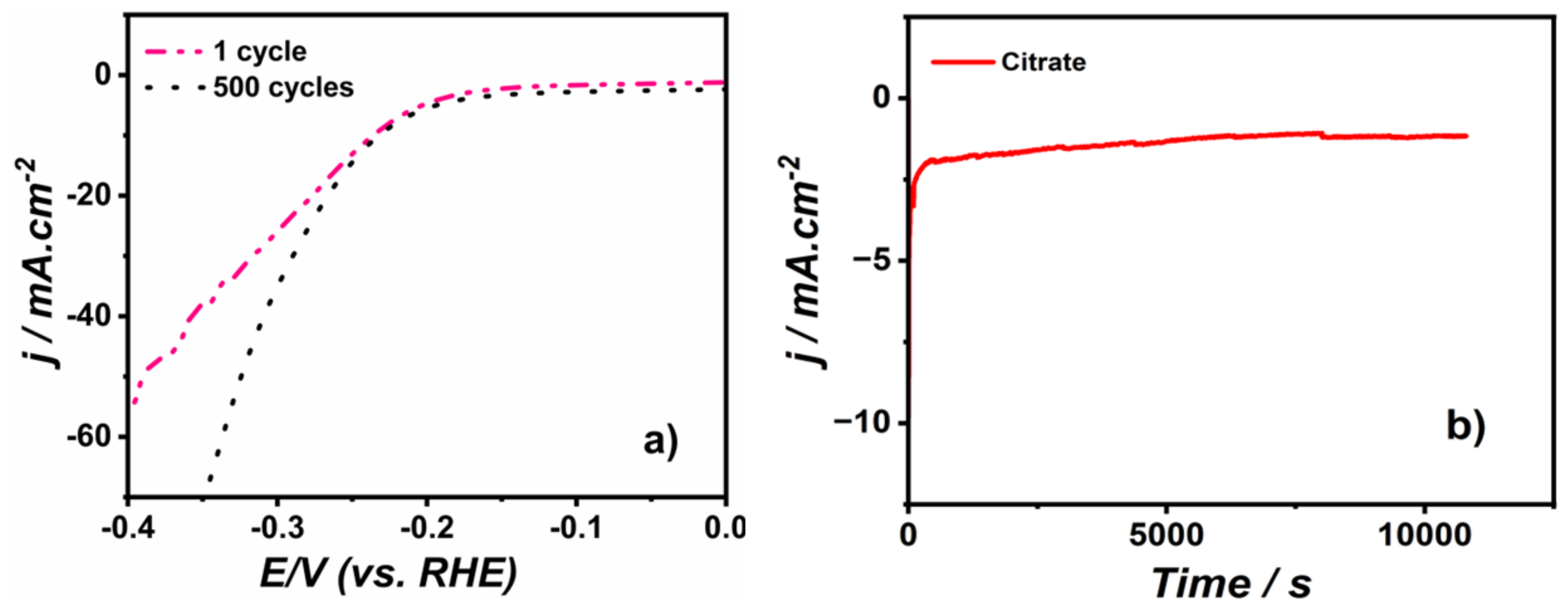
3.14. Stability and Durability Measurements

The durability and stability measurements of the fabricated Ni thin film from the citrate electrolyte are studied. Figure 14a exhibits the LSV curves for 1 M NaOH at the fabricated Ni thin film from the citrate electrolyte with pH 1.47 at a deposition potential of −1.2 V under the influence of B after 1 cycle and after 500 cycles. It is noticed that the overpotential for HER is almost the same and is not affected, which means this film has good durability towards HER. Figure 14b represents the chronoamperometric curve for investigating the stability of the fabricated Ni from the citrate electrolyte in 1 M NaOH for 3 h. It is noticed that the current retains a percentage of 70% of its initial current, which indicates that this Ni thin film has good mechanical properties and stability towards HER.
Therefore, we compare the fabricated Ni from the citrate under the influence of the magnetic field and other catalysts for HER. It is found that the fabricated Ni, by Laszczyńska et al., possesses an overpotential value of 456 mV to reach a current density of 10 mA cm−2. Moreover, the composite of Ni-WS2 produces 291 mV, and Ni-Mo produces 534 mV to reach a current density of 10 mA cm−2 [67]. We notice that our catalyst produces a lower overpotential value of −231 mV to reach a current density of 10 mA cm−2 compared with these composites. Furthermore, Arumugam et al. synthesized a hierarchical NiCo2S4 nanowire array, which gave an overpotential value of −210 mV for HER to reach a current density of 10 mA cm−2 [68]. Yinliang et al. prepared a Ni porous electrode, which produced an overpotential value of −252 mV and a Tafel slope value of 252 mV dec−1, and they calculated the exchange current density for the fabricated porous Ni electrode, which gave a value of 2.28 × 10⁻³ A cm−2 [69]. To conclude, from the above results of different Ni electrocatalysts, our fabricated Ni electrocatalyst produces the smallest overpotential value and the highest j0 value if it is compared with a fabricated single Ni electrode, suggesting that insertion of other metals to prepare other electrocatalysts using this method is a promising approach.

4. Conclusions

The composition of the electrolyte used for the electrodeposition process for Ni thin films plays an important role in the formation of different surface morphologies. Moreover, the impact of the optimization parameters changes the pH and the deposition potential effect on their surface morphologies. Furthermore, the influence of the magnetic field on the electrodeposition process of Ni thin films from acetate, borate, and citrate electrolytes has shown a great change in the surface properties, changing the wettability properties and hence the catalytic performance towards HER based on the changing of the surface morphology. The fabricated Ni thin film from the citrate electrolyte has the best catalytic properties towards HER as it has the lowest overpotential value of 231 mV and the highest exchange current density value of 19.8 × 10⁻¹, suggesting that it has the highest catalytic activity compared with the other fabricated Ni films from the acetate and borate electrolyte.

Supplementary Materials

The following supporting information can be downloaded at: https://0-www-mdpi-com.brum.beds.ac.uk/article/10.3390/coatings13101816/s1, Table S1: Values of overpotential values for HER of fabricated Ni electrodes from acetate bath at pH 1.47 and deposition potential −1.3 V. Table S2: Values of overpotential values for HER of fabricated Ni electrodes from acetate bath at pH 2.5 and deposition potential −1.4 V. Table S3: Values of overpotential values for HER of fabricated Ni electrodes from acetate bath at pH 4.4 and deposition potential −1.1 V. Table S4: Values of overpotential values for HER of fabricated Ni electrodes from acetate bath at pH 4.4 and deposition potential −1.2 V. Table S5: Values of overpotential values for HER of fabricated Ni electrodes from borate bath at pH 1.47 and deposition potential −1.1 V. Table S6: Values of overpotential values for HER of fabricated Ni electrodes from borate bath at pH 1.47 and deposition potential −1.2 V. Table S7: Values of overpotential values for HER of fabricated Ni electrodes from borate bath at pH 2.5 and deposition potential −1.2 V. Table S8: Values of overpotential values for HER of fabricated Ni electrodes from borate bath at pH 3.7 and deposition potential −1.2 V. Table S9: Values of overpotential values for HER of fabricated Ni electrodes from citrate bath at pH 1.47 and deposition potential −1.2 V. Table S10: Values of overpotential values for HER of fabricated Ni electrodes from citrate bath at pH 2.5 and deposition potential −1.2 V. Table S11: Values of overpotential values for HER of fabricated Ni electrodes from citrate bath at pH 3.7 and deposition potential −1.2 V. Table S12: Values of overpotential values for HER of fabricated Ni electrodes from citrate bath at pH 4.4 and deposition potential −1.2 V.

Author Contributions

Conceptualization, S.E.; performing the experiments, writing—original draft preparation, D.K.; writing—original draft preparation, P.Z. All authors have read and agreed to the published version of the manuscript.

Funding

This research received no external funding.

Institutional Review Board Statement

Not applicable.

Informed Consent Statement

Not applicable.

Data Availability Statement

Data are contained within the article.

Conflicts of Interest

The authors declare no conflict of interest.

References

  1. Wei, Y.; Wang, R.; Meng, L.; Wang, Y.; Li, G.; Xin, S.; Zhao, X.; Zhang, K. Hydrogen Generation from Alkaline NaBH4 Solution Using a Dandelion-like Co–Mo–B Catalyst Supported on Carbon Cloth. Int. J. Hydrogen Energy 2017, 42, 9945–9951. [Google Scholar] [CrossRef]
  2. Wang, M.; Fu, W.; Du, L.; Wei, Y.; Rao, P.; Wei, L.; Zhao, X.; Wang, Y.; Sun, S.; Wang, M.; et al. Surface Engineering by Doping Manganese into Cobalt Phosphide towards Highly Efficient Bifunctional HER and OER Electrocatalysis. Appl. Surf. Sci. 2020, 515, 146059. [Google Scholar] [CrossRef]
  3. Rao, P.; Cui, P.; Yang, L.; Wang, M.; Wang, S.; Cai, H.; Wang, Y.; Zhao, X.; Wilkinson, D.P.; Zhang, J.; et al. Surface Plasma-Etching Treatment of Cobalt Nanoparticles-Embedded Honeysuckle-like Nitrogen-Doped Carbon Nanotubes to Produce High-Performance Catalysts for Rechargeable Zinc-Air Batteries. J. Power Sources 2020, 453, 227858. [Google Scholar] [CrossRef]
  4. Wang, J.G.; Hua, W.; Li, M.; Liu, H.; Shao, M.; Wei, B. Structurally Engineered Hyperbranched NiCoP Arrays with Superior Electrocatalytic Activities toward Highly Efficient Overall Water Splitting. ACS Appl. Mater. Interfaces 2018, 10, 41237–41245. [Google Scholar] [CrossRef]
  5. Paul, R.; Du, F.; Dai, L.; Ding, Y.; Lin Wang, Z.; Wei, F.; Roy, A.; Paul, R.; Du, F.; Dai, L.; et al. 3D Heteroatom-Doped Carbon Nanomaterials as Multifunctional Metal-Free Catalysts for Integrated Energy Devices. Adv. Mater. 2019, 31, 1805598. [Google Scholar] [CrossRef]
  6. Hung, S.F.; Hsu, Y.Y.; Chang, C.J.; Hsu, C.S.; Suen, N.T.; Chan, T.S.; Chen, H.M. Unraveling Geometrical Site Confinement in Highly Efficient Iron-Doped Electrocatalysts toward Oxygen Evolution Reaction. Adv. Energy Mater. 2018, 8, 1701686. [Google Scholar] [CrossRef]
  7. Patel, P.P.; Hanumantha, P.J.; Datta, M.K.; Velikokhatnyi, O.I.; Hong, D.; Poston, J.A.; Manivannan, A.; Kumta, P.N. Cobalt Based Nanostructured Alloys: Versatile High Performance Robust Hydrogen Evolution Reaction Electro-Catalysts for Electrolytic and Photo-Electrochemical Water Splitting. Int. J. Hydrogen Energy 2017, 42, 17049–17062. [Google Scholar] [CrossRef]
  8. Elsharkawy, S.; Hammad, S.; El-hallag, I. Electrodeposition of Ni Nanoparticles from Deep Eutectic Solvent and Aqueous Solution Promoting High Stability Electrocatalyst for Hydrogen and Oxygen Evolution Reactions. J. Solid State Electron. 2022, 26, 1501–1517. [Google Scholar] [CrossRef]
  9. Chen, L.; Dong, X.; Wang, Y.; Xia, Y. Separating Hydrogen and Oxygen Evolution in Alkaline Water Electrolysis Using Nickel Hydroxide. Nat. Commun. 2016, 7, 11741. [Google Scholar] [CrossRef]
  10. Najafpour, M.M.; Renger, G.; Hołyńska, M.; Moghaddam, A.N.; Aro, E.M.; Carpentier, R.; Nishihara, H.; Eaton-Rye, J.J.; Shen, J.R.; Allakhverdiev, S.I. Manganese Compounds as Water-Oxidizing Catalysts: From the Natural Water-Oxidizing Complex to Nanosized Manganese Oxide Structures. Chem. Rev. 2016, 116, 2886–2936. [Google Scholar] [CrossRef] [PubMed]
  11. Cao, L.; Luo, Q.; Liu, W.; Lin, Y.; Liu, X.; Cao, Y.; Zhang, W.; Wu, Y.; Yang, J.; Yao, T.; et al. Identification of Single-Atom Active Sites in Carbon-Based Cobalt Catalysts during Electrocatalytic Hydrogen Evolution. Nat. Catal. 2018, 2, 134–141. [Google Scholar] [CrossRef]
  12. Yu, F.; Zhou, H.; Huang, Y.; Sun, J.; Qin, F.; Bao, J.; Goddard, W.A.; Chen, S.; Ren, Z. High-Performance Bifunctional Porous Non-Noble Metal Phosphide Catalyst for Overall Water Splitting. Nat. Commun. 2018, 9, 2551. [Google Scholar] [CrossRef] [PubMed]
  13. Wei, Y.; Huang, X.; Wang, J.; Yu, H.; Zhao, X.; Cheng, D. Synthesis of Bifunctional Non-Noble Monolithic Catalyst Co-W-P/Carbon Cloth for Sodium Borohydride Hydrolysis and Reduction of 4-Nitrophenol. Int. J. Hydrogen Energy 2017, 42, 25860–25868. [Google Scholar] [CrossRef]
  14. Shedid, M.H.; Elshokary, S. Hydrogen Production from an Alkali Electrolyzer Operating with Egypt Natural Resources. Smart Grid Renew. Energy 2015, 6, 14–25. [Google Scholar] [CrossRef]
  15. Wang, L.; Wen, B.; Bai, X.; Liu, C.; Yang, H. NiCo Alloy/Carbon Nanorods Decorated with Carbon Nanotubes for Microwave Absorption. ACS Appl. Nano Mater. 2019, 2, 7827–7838. [Google Scholar] [CrossRef]
  16. Li, S.; Sirisomboonchai, S.; Yoshida, A.; An, X.; Hao, X.; Abudula, A.; Guan, G. Bifunctional CoNi/CoFe2O4 /Ni Foam Electrodes for Efficient Overall Water Splitting at a High Current Density. J. Mater. Chem. A Mater. 2018, 6, 19221–19230. [Google Scholar] [CrossRef]
  17. Yu, J.; Cao, Q.; Li, Y.; Long, X.; Yang, S.; Clark, J.K.; Nakabayashi, M.; Shibata, N.; Delaunay, J.J. Defect-Rich NiCeOx Electrocatalyst with Ultrahigh Stability and Low Overpotential for Water Oxidation. ACS Catal. 2019, 9, 1605–1611. [Google Scholar] [CrossRef]
  18. Li, Y.; Huang, B.; Sun, Y.; Luo, M.; Yang, Y.; Qin, Y.; Wang, L.; Li, C.; Lv, F.; Zhang, W.; et al. Multimetal Borides Nanochains as Efficient Electrocatalysts for Overall Water Splitting. Small 2019, 15, 1804212. [Google Scholar] [CrossRef]
  19. Skibińska, K.; Kutyła, D.; Yang, X.; Krause, L.; Marzec, M.M.; Żabiński, P. Rhodium-Decorated Nanoconical Nickel Electrode Synthesis and Characterization as an Electrochemical Active Cathodic Material for Hydrogen Production. Appl. Surf. Sci. 2022, 592, 153326. [Google Scholar] [CrossRef]
  20. Kutyła, D.; Salcı, A.; Kwiecińska, A.; Kołczyk-Siedlecka, K.; Kowalik, R.; Żabiński, P.; Solmaz, R. Catalytic Activity of Electrodeposited Ternary Co–Ni–Rh Thin Films for Water Splitting Process. Int. J. Hydrogen Energy 2020, 45, 34805–34817. [Google Scholar] [CrossRef]
  21. Kutyła, D.; Kołczyk-Siedlecka, K.; Kwiecińska, A.; Skibińska, K.; Kowalik, R.; Żabiński, P. Preparation and Characterization of Electrodeposited Ni-Ru Alloys: Morphological and Catalytic Study. J. Solid State Electr. 2019, 23, 3089–3097. [Google Scholar] [CrossRef]
  22. Kutyła, D.; Kołczyk, K.; Żabiński, P.; Kowalik, R.; Kwiecińska, A.; Skibinska, K. Investigation of Ruthenium Thin Layers Electrodeposition Process under Galvanostatic Conditions from Chloride Solutions. Russ. J. Electrochem. 2020, 56, 214–221. [Google Scholar] [CrossRef]
  23. Davodi, F.; Mühlhausen, E.; Tavakkoli, M.; Sainio, J.; Jiang, H.; Gökce, B.; Marzun, G.; Kallio, T. Catalyst Support Effect on the Activity and Durability of Magnetic Nanoparticles: Toward Design of Advanced Electrocatalyst for Full Water Splitting. ACS Appl. Mater. Interfaces 2018, 10, 31300–31311. [Google Scholar] [CrossRef]
  24. He, Y.; Han, X.P.; Rao, D.W.; Zhang, Y.D.; Zhao, J.; Zhong, C.; Hu, W.B.; Wei, W.F.; Deng, Y.D. Charge Redistribution of Co on Cobalt (II) Oxide Surface for Enhanced Oxygen Evolution Electrocatalysis. Nano Energy 2019, 61, 267–274. [Google Scholar] [CrossRef]
  25. Liu, D.; Dai, L.; Lin, X.; Chen, J.F.; Zhang, J.; Feng, X.; Müllen, K.; Zhu, X.; Dai, S. Chemical Approaches to Carbon-Based Metal-Free Catalysts. Adv. Mater. 2019, 31, 1804863. [Google Scholar] [CrossRef] [PubMed]
  26. Mahmood, J.; Ali, M.; Anjum, R.; Shin, S.-H.; Ahmad, I.; Noh, H.-J.; Kim, S.-J.; Jeong, Y.; Lee, J.S.; Baek, J.-B.; et al. Encapsulating Iridium Nanoparticles Inside a 3D Cage-Like Organic Network as an Efficient and Durable Catalyst for the Hydrogen Evolution Reaction. Adv. Mater. 2018, 30, 1805606. [Google Scholar] [CrossRef]
  27. Wei, Y.; Meng, W.; Wang, Y.; Gao, Y.; Qi, K.; Zhang, K. Fast Hydrogen Generation from NaBH4 Hydrolysis Catalyzed by Nanostructured Co–Ni–B Catalysts. Int. J. Hydrogen Energy 2017, 42, 6072–6079. [Google Scholar] [CrossRef]
  28. Xiao, Y.; Zhang, P.; Zhang, X.; Dai, X.; Ma, Y.; Wang, Y.; Jiang, Y.; Liu, M.; Wang, Y. Bimetallic Thin Film NiCo–NiCoO2@NC as a Superior Bifunctional Electrocatalyst for Overall Water Splitting in Alkaline Media. J. Mater. Chem. A Mater. 2017, 5, 15901–15912. [Google Scholar] [CrossRef]
  29. Gund, G.S.; Dubal, D.P.; Shinde, S.S.; Lokhande, C.D. Short Communication. Ceram. Int. 2013, 6, 7255–7261. [Google Scholar] [CrossRef]
  30. Elsharkawy, S.; Hammad, S.; El-hallag, I. The effect of electrodeposition potential on catalytic properties of Ni nanoparticles for hydrogen evolution reaction (HER) in alkaline media. J. Appl. Electrochem. 2022, 52, 907–918. [Google Scholar] [CrossRef]
  31. Gong, M.; Wang, D.Y.; Chen, C.C.; Hwang, B.J.; Dai, H. A Mini Review on Nickel-Based Electrocatalysts for Alkaline Hydrogen Evolution Reaction. Nano Res. 2015, 9, 28–46. [Google Scholar] [CrossRef]
  32. Gund, G.S.; Dubal, D.P.; Shinde, S.S.; Lokhande, C.D. Architectured Morphologies of Chemically Prepared NiO/MWCNTs Nanohybrid Thin Films for High Performance Supercapacitors. ACS Appl. Mater. Interfaces 2014, 6, 3176–3188. [Google Scholar] [CrossRef]
  33. Dubal, D.P.; Gomez-Romero, P.; Sankapal, B.R.; Holze, R. Nickel Cobaltite as an Emerging Material for Supercapacitors: An Overview. Nano Energy 2015, 11, 377–399. [Google Scholar] [CrossRef]
  34. Yu, X.; Zhao, J.; Zheng, L.R.; Tong, Y.; Zhang, M.; Xu, G.; Li, C.; Ma, J.; Shi, G. Hydrogen Evolution Reaction in Alkaline Media: Alpha- or Beta-Nickel Hydroxide on the Surface of Platinum. ACS Energy Lett. 2018, 3, 237–244. [Google Scholar] [CrossRef]
  35. Balram, A.; Zhang, H.; Santhanagopalan, S. In Situ Decoration of Stainless Steel Nanoparticles for Synergistic Enhancement of α-Ni(OH)2 Oxygen Evolution Reaction Catalysis. Mater. Chem. Front. 2017, 1, 2376–2382. [Google Scholar] [CrossRef]
  36. Jin, C.; Zhou, N.; Wang, Y.; Li, X.; Chen, M.; Dong, Y.; Yu, Z.; Liang, Y.; Qu, D.; Dong, Y.; et al. 3D Porous and Self-Supporting Ni Foam@graphene@Ni3S2 as a Bifunctional Electrocatalyst for Overall Water Splitting in Alkaline Solution. J. Electroanal. Chem. 2020, 858, 113795. [Google Scholar] [CrossRef]
  37. Yao, K.; Zhai, M.; Ni, Y. α-Ni(OH)2·0.75H2O Nanofilms on Ni Foam from Simple NiCl2 Solution: Fast Electrodeposition, Formation Mechanism and Application as an Efficient Bifunctional Electrocatalyst for Overall Water Splitting in Alkaline Solution. Electrochim. Acta 2019, 301, 87–96. [Google Scholar] [CrossRef]
  38. Skibińska, K.; Semeniuk, S.; Kutyła, D.; Kołczyk-Siedlecka, K.; Jędraczka, A.; Żabiński, P. Study on Synthesis and Modification of Conical Ni Structures by One-Step Method. Arch. Metall. Mater. 2021, 66, 861–869. [Google Scholar] [CrossRef]
  39. Hashemzadeh, M.; Raeissi, K.; Ashrafizadeh, F.; Khorsand, S. Effect of Ammonium Chloride on Microstructure, Super-Hydrophobicity and Corrosion Resistance of Nickel Coatings. Surf. Coat. Technol. 2015, 283, 318–328. [Google Scholar] [CrossRef]
  40. Hang, T.; Hu, A.; Ling, H.; Li, M.; Mao, D. Super-Hydrophobic Nickel Films with Micro-Nano Hierarchical Structure Prepared by Electrodeposition. Appl. Surf. Sci. 2010, 256, 2400–2404. [Google Scholar] [CrossRef]
  41. Hang, T.; Li, M.; Fei, Q.; Mao, D. Characterization of Nickel Nanocones Routed by Electrodeposition without Any. Nanotechnology 2007, 19, 035201. [Google Scholar] [CrossRef] [PubMed]
  42. Kowalik, R.; Mech, K.; Kutyla, D.; Tokarski, T.; Zabinski, P. Magnetic field effect on the electrodeposition of ZnSe. Magnetohydrodynamics 2015, 51, 345–351. [Google Scholar] [CrossRef]
  43. Dobosz, I.; Kutyła, D.; Kac, M.; Włoch, G.; Żabiński, P. The Influence of Homogenous External Magnetic Field on Morphology and Magnetic Properties of CoRu Nanowire Arrays. J. Mater. Sci. Eng. B 2020, 262, 114795. [Google Scholar] [CrossRef]
  44. Qi, J.; Wang, X.; Shao, Y.; Li, L.; Wang, C. Effects of Magnetic Field on Open-Circuit Potential of the Ni|HNO3 + NaCl System. Int. J. Electrochem. Sci. 2021, 16, 210521. [Google Scholar] [CrossRef]
  45. Sudibyo, M.B.; Aziz, N. Influences of Magnetic Field on the Fractal Morphology in Copper Electrodeposition. IOP Conf. Ser. Mater. Sci. Eng. 2018, 285, 012021. [Google Scholar] [CrossRef]
  46. Bund, A.; Ispas, A. Influence of a Static Magnetic Field on Nickel Electrodeposition Studied Using an Electrochemical Quartz Crystal Microbalance, Atomic Force Microscopy and Vibrating Sample Magnetometry. J. Electroanal. Chem. 2005, 575, 221–228. [Google Scholar] [CrossRef]
  47. Bund, A.; Koehler, S.; Kuehnlein, H.H.; Plieth, W. Magnetic Field Effects in Electrochemical Reactions. Electrochim. Acta 2003, 49, 147–152. [Google Scholar] [CrossRef]
  48. Ragsdale, S.R.; Grant, K.M.; White, H.S. Electrochemically Generated Magnetic Forces. Enhanced Transport of a Paramagnetic Redox Species in Large, Nonuniform Magnetic Fields. J. Am. Chem. Soc. 1998, 120, 13461–13468. [Google Scholar] [CrossRef]
  49. Yang, Y.; Grant, K.M.; White, H.S.; Chen, S. Magnetoelectrochemistry of Nitrothiophenolate-Functionalized Gold Nanoparticles. Langmuir 2003, 19, 9446–9449. [Google Scholar] [CrossRef]
  50. O’Reilly, C.; Hinds, G.; Coey, J.M.D. Effect of a Magnetic Field on Electrodeposition: Chronoamperometry of Ag, Cu, Zn, and Bi. J. Electrochem. Soc. 2001, 148, C674. [Google Scholar] [CrossRef]
  51. Monzon, L.M.A.; Coey, J.M.D. Magnetic Fields in Electrochemistry: The Lorentz Force. A Mini-Review. Electrochem. Commun. 2014, 42, 38–41. [Google Scholar] [CrossRef]
  52. Mech, K.; Gajewska, M.; Marzec, M.; Szaciłowski, K. On the Influence of Magnetic Field on Electrodeposition of Ni–TiO2 Composites from a Citrate Baths. Mater. Chem. Phys. 2020, 255, 123550. [Google Scholar] [CrossRef]
  53. Xia, F.; Li, Q.; Ma, C.; Guo, X. Preparation and Characterization of Ni–AlN Nanocoatings Deposited by Magnetic Field Assisted Electrodeposition Technique. Ceram. Int. 2020, 46, 2500–2509. [Google Scholar] [CrossRef]
  54. Nikolic, N.D.; Wang, H.; Cheng, H.; Guerrero, C.A.; Garcia, N. Influence of the Magnetic Field and Magnetoresistance on the Electrodeposition of Ni Nanocontacts in Thin Films and Microwires. J. Magn. Magn. Mater. 2004, 272–276, 2436–2438. [Google Scholar] [CrossRef]
  55. Shen, L.; Xu, M.; Jiang, W.; Qiu, M.; Fan, M.; Ji, G.; Tian, Z. A Novel Superhydrophobic Ni/Nip Coating Fabricated by Magnetic Field Induced Selective Scanning Electrodeposition. Appl. Surf. Sci. 2019, 489, 25–33. [Google Scholar] [CrossRef]
  56. Wang, J.; Xu, F.; Jin, H.; Chen, Y.; Wang, Y. Non-Noble Metal-Based Carbon Composites in Hydrogen Evolution Reaction: Fundamentals to Applications. Adv. Mater 2017, 29, 1605838. [Google Scholar] [CrossRef] [PubMed]
  57. Uhlemann, M.; Krause, A.; Gebert, A. Effect of a Magnetic Field on the Local PH Value in Front of the Electrode Surface during Electrodeposition of Co. J. Electroanal. Chem. 2005, 577, 19–24. [Google Scholar] [CrossRef]
  58. Ji, J.; Cooper, W.C.; Dreisinger, D.B.; Peters, E. Surface PH Measurements during Nickel Electrodeposition. J. Appl. Electrochem. 1995, 25, 642–650. [Google Scholar] [CrossRef]
  59. Koza, J.A.; Uhlemann, M.; Gebert, A.; Schultz, L. The Effect of a Magnetic Field on the PH Value in Front of the Electrode Surface during the Electrodeposition of Co, Fe and CoFe Alloys. J. Electroanal. Chem. 2008, 617, 194–202. [Google Scholar] [CrossRef]
  60. Long, Q.; Zhong, Y.; Wu, J. Effect of Magnetic Fields on the Behavior of Iron Electrodeposition. Int. J. Electrochem. Sci. 2020, 15, 6955–6968. [Google Scholar] [CrossRef]
  61. Uhlemann, M.; Krause, A.; Chopart, J.P.; Gebert, A. Electrochemical Deposition of Co under the Influence of High Magnetic Fields. J. Electrochem. Soc. 2005, 152, C817. [Google Scholar] [CrossRef]
  62. El-Hallag, I.; Elsharkawy, S.; Hammad, S. Electrodeposition of Ni Nanoparticles from Deep Eutectic Solvent and Aqueous Solution as Electrocatalyst for Methanol Oxidation in Acidic Media. Int. J. Hydrogen Energy 2021, 46, 15442–15453. [Google Scholar] [CrossRef]
  63. Van Nguyen, T.; Tekalgne, M.; Nguyen, T.P.; Van Le, Q.; Ahn, S.H.; Kim, S.Y. Electrocatalysts Based on MoS2 and WS2 for Hydrogen Evolution Reaction: An Overview. Battery Energy 2023, 2, 20220057. [Google Scholar] [CrossRef]
  64. Wang, H.; Ma, Q.; Sun, F.; Shao, Y.; Zhang, D.; Sun, H.; Li, Z.; Wang, Q.; Qi, J.; Wang, B. Oxygen Vacancy and Interface Effect Adjusted Hollow Dodecahedrons for Efficient Oxygen Evolution Reaction. Molecules 2023, 28, 5620. [Google Scholar] [CrossRef]
  65. Zhang, Z.; Chen, K.; Zhao, Q.; Huang, M.; Ouyang, X. Electrocatalytic and Photocatalytic Performance of Noble Metal Doped Monolayer MoS2 in the Hydrogen Evolution Reaction: A First Principles Study. Nano Mater. Sci. 2021, 3, 89–94. [Google Scholar] [CrossRef]
  66. Xie, Z.; He, P.; Du, L.; Dong, F.; Dai, K.; Zhang, T. Comparison of Four Nickel-Based Electrodes for Hydrogen Evolution Reaction. Electrochim. Acta 2013, 88, 390–394. [Google Scholar] [CrossRef]
  67. Laszczyńska, A.; Tylus, W. Improving the Electrocatalytic Performance for the Hydrogen Evolution Reaction in the Electrodeposited Ni-Based Matrix by Incorporating WS2 Nanoparticles. J. Electrochem. Soc. 2023, 170, 076502. [Google Scholar] [CrossRef]
  68. Sivanantham, A.; Ganesan, P.; Shanmugam, S. Hierarchical NiCo2S4 Nanowire Arrays Supported on Ni Foam: An Efficient and Durable Bifunctional Electrocatalyst for Oxygen and Hydrogen Evolution Reactions. Adv. Funct. Mater. 2016, 26, 4661–4672. [Google Scholar] [CrossRef]
  69. Cao, Y.; Liu, H.; Bo, X.; Wang, F. Highly Active Porous Nickel-Film Electrode via Polystyrene Microsphere Template-Assisted Composite Electrodeposition for Hydrogen-Evolution Reaction in Alkaline Medium. Sci. China Chem. 2015, 58, 501–507. [Google Scholar] [CrossRef]
Scheme 1. Representation of the electrodeposition process under the influence of the magnetic field in a perpendicular direction (A) to the electrode surface and (B) in a parallel direction.
Coatings 13 01816 sch001
Figure 1. SEM images of Ni thin films fabricated from acetate electrolyte at copper electrode surface (a) at pH 1.47 with deposition potential of −1.1 V, (b) −1.2 V, (c) −1.3 V, (d) −1.4 V, (e) at pH 2.5 with deposition potential of −1.1 V, (f) (−1.2) V, (g) (−1.3 V), (h) (−1.4 V), (i) at pH 3.7 with deposition potential of −1.1 V, (j) −1.2 V, (k) −1.3 V, (l) −1.4 V, (m) at pH 4.4 with deposition potential of −1.1 V, (n) −1.2 V, (o) −1.3 V, and (p) −1.4 V.
Coatings 13 01816 g001
Figure 2. SEM images of Ni thin films fabricated from borate electrolyte at copper electrode surface (a) at pH 1.47 with deposition potential of −1.1 V, (b) −1.2 V, (c) −1.3 V, (d) −1.4 V, (e) at pH 2.5 with deposition potential of −1.1 V, (f) −1.2 V, (g) −1.3 V, (h) −1.4 V, at pH 3.7 with deposition potential of (i) −1.1 V, (j) −1.2 V, (k) −1.3 V, (l) −1.4 V, (m) at pH 4.4 with deposition potential of −1.1 V, (n) −1.2 V, (o) −1.3 V, and (p) −1.4 V.
Coatings 13 01816 g002
Figure 3. SEM images of fabricated Ni thin films from citrate at copper electrode surface at deposition potential of −1.2 V with different pH values (a) at pH 1.47, (b) at pH 2.5, (c) at pH 3.7, and (d) at pH 4.4.
Coatings 13 01816 g003
Figure 4. SEM images of fabricated Ni thin films from citrate at copper electrode surface at pH 3.7 with different deposition potentials values of (a) −1.1 V, (b) −1.2 V, (c) −1.3 V, and (d) −1.4 V.
Coatings 13 01816 g004
Figure 5. SEM images of fabricated Ni thin films in the absence and presence of the magnetic field. (ac) Ni thin films prepared from pH 2.5 at a deposition potential of −1.4 V in the absence of B (a), presence of (B) (b), and (B) (c). (df) Ni thin films prepared from pH 1.47 at a deposition potential of −1.3 V in the absence of B (d), presence of (B) (e), and (B) (f). (gi) Ni thin films prepared from pH 4.4 at a deposition potential of −1.1 V in the absence of B (g), presence of (B) (h), and (B) (i). (jl) Ni thin films prepared from pH 4.4 at a deposition potential of −1.2 V in the absence of B (j), presence of (B) (k), and (B) (l). Yellow boxes and circles show the percentage of the presence of the holes caused by the hydrogen evolution reaction.
Coatings 13 01816 g005
Figure 6. SEM images of fabricated Ni thin films in the absence and presence of the magnetic field. (ac) Ni thin films prepared from pH 1.47 at a deposition potential of −1.1 V in the absence of B (a), presence of (B) (b), and (B) (c). (df) Ni thin films prepared from pH 1.47 at a deposition potential of −1.2 V in the absence of B (d), presence of (B) (e), and (B) (f). (gi) Ni thin films prepared from pH 2.5 at a deposition potential of −1.2 V in the absence of B (g), presence of (B) (h), and (B) (i). (jl) Ni thin films prepared from pH 3.7 at a deposition potential of −1.2 V in the absence of B (j), presence of (B) (k), and (B) (l). These yellow circles indication of the percentage of holes and cracks present on the surface.
Coatings 13 01816 g006
Figure 7. SEM images of fabricated Ni thin films in the absence and presence of the magnetic field. (ac) Ni thin films prepared from pH 1.47 at a deposition potential of −1.2 V in the absence of B (a), presence of (B) (b), and (B) (c). (df) Ni thin films prepared from pH 2.5 at a deposition potential of −1.2 V in the absence of B (d), presence of (B) (e), and (B) (f). (gi) Ni thin films prepared from pH 3.7 at a deposition potential of −1.2 V in the absence of B (g), presence of (B) (h), and (B) (i). (jl) Ni thin films prepared from pH 4.4 at a deposition potential of −1.2 V in the absence of B (j), presence of (B) (k), and (B) (l). Yellow circles indicates the number of holes present on the surface.
Coatings 13 01816 g007
Figure 8. Chart representation of the contact angles of different Ni thin films from different electrolytes in the absence of B and presence of (B) and (B) to the electrode surface.
Coatings 13 01816 g008
Figure 9. XRD spectrum for Ni thin films from citrate at pH 1.47 at a deposition potential of −1.2 V in the presence of B, borate electrolyte at pH 2.5 in the absence of B, and acetate electrolyte at pH 2.5 at a deposition potential of −1.4 V in the presence of B and Cu substrate electrode.
Coatings 13 01816 g009
Figure 10. (a,b) LSV and Tafel plot for fabricated Ni electrodes from acetate bath at pH 1.47 and deposition potential of −1.3 V. (c,d) LSV and Tafel plot for Ni films fabricated at pH 2.5 and deposition potential of −1.4 V. (e,f) LSV and Tafel plot for fabricated Ni electrodes at pH 4.4 and deposition potential of −1.1 V. (g,h) LSV and Tafel plot for fabricated Ni electrodes from acetate bath at pH 4.4 and deposition potential of −1.2 V.
Coatings 13 01816 g010
Figure 11. (a,b) LSV and Tafel plot for fabricated Ni electrodes from borate bath at pH 1.47 and deposition potential of −1.1 V in the absence and presence of B. (c,d) pH 1.47 and deposition potential of −1.2 V. (e,f) pH 2.5 and deposition potential of −1.2 V. (g,h) pH 3.7 and deposition potential of −1.2 V.
Coatings 13 01816 g011
Figure 12. (a,b) LSV and Tafel plot for fabricated Ni electrodes from citrate bath at pH 1.47 and deposition potential of −1.2 V in the absence and presence of B. (c,d) pH 2.5 and deposition potential of −1.2 V. (e,f) pH 3.7 and deposition potential of −1.2 V. (g,h) pH 4.4 and deposition potential of −1.2 V.
Coatings 13 01816 g012
Figure 13. (a) Polarization curves of HER in 1 M NaOH at scan rate 5 mV s−1 and room temperature at fabricated Ni deposit from citrate at pH 1.47 at deposition potential of −1.2 V in the presence of B, borate electrolyte at pH 2.5 in the absence of B, and acetate electrolyte at pH 2.5 at deposition potential of −1.4 V in the presence of B. (b) Tafel plots for the polarization curves of HER for different electrodes.
Coatings 13 01816 g013
Figure 14. (a) LSV curves for HER in 1M NaOH after 1 cycle and 500 cycles for deposited Ni from citrate. (b) The chronoamperometry time–current curve for fabricated Ni from citrate.
Coatings 13 01816 g014
Table 1. Composition of used electrolytes.
A0.2 M NiCl2·6H2O0.2 M NiSO4·7H2O0.4 M Acetic acid
B0.2 M NiCl2·6H2O0.2 M NiSO4·7H2O0.2 M Boric acid
C0.2 M NiCl2·6H2O0.2 M NiSO4·7H2O0.4 M Citric acid
Table 2. Values of overpotential, Tafel slopes, and kinetics parameters for different fabricated electrodes in 1 M NaOH at room temperature and scan rate 10 mV s−1 in the case of HER.
Ni Filmsη10 (mV)Tafel Slopes (mV dec−1)j0 (A·cm−2)α
Ni thin film from citrate23111819.8 × 10−10.20
Ni thin film from acetate2912123.38 × 10−10.16
Ni thin film from borate3191558.9 × 10−20.10
Disclaimer/Publisher’s Note: The statements, opinions and data contained in all publications are solely those of the individual author(s) and contributor(s) and not of MDPI and/or the editor(s). MDPI and/or the editor(s) disclaim responsibility for any injury to people or property resulting from any ideas, methods, instructions or products referred to in the content.

