Review

A Review on Geothermal Heat Exchangers: Challenges, Coating Methods, and Coating Materials

by
Arunima Bhuvanendran Nair Jayakumari
1,†,
Nigar Gul Malik
1,†,
Garima Mittal
1,
David Martelo
2,
Namrata Kale
2 and
Shiladitya Paul
1,2,*
1
Materials Innovation Centre, School of Engineering, University of Leicester, Leicester LE1 7RH, UK
2
Materials Performance and Integrity Technology Group, TWI, Cambridge CB21 6AL, UK
*
Author to whom correspondence should be addressed.
These authors contributed equally to this work.
Submission received: 29 September 2023 / Revised: 15 November 2023 / Accepted: 20 November 2023 / Published: 23 November 2023
(This article belongs to the Special Issue Recent Research in Coatings for Harsh Environments)

Abstract

:
Geothermal energy is likely to be a significant contributor in achieving sustainable energy goals and net-zero emissions targets. Within geothermal power plants, heat exchangers play a critical role in harnessing this renewable energy source. However, these heat exchangers encounter significant challenges when exposed to geothermal fluids, including erosion, corrosion, and scaling, which adversely affects their performance and longevity. The current review focuses on surface engineering techniques, particularly coatings, as a highly effective and economically viable solution to address these challenges in geothermal heat exchangers. The review begins by providing an overview of geothermal energy, its significance in the context of sustainability and the important role played by heat exchangers in geothermal power generation, followed by the challenges and their impact on heat exchangers. The subsequent section focuses on surface engineering by coatings and its types employed to enhance the performance of heat exchangers. In the final part, the reader is presented with an overview of the challenges associated with the application of coatings in geothermal heat exchangers and potential future directions in this field. This review offers a detailed understanding of the critical role coatings play in improving the efficiency and service life of heat exchangers in geothermal power plants.

1. Introduction

According to International Energy Agency (IEA) report of 2022, global energy-related CO2 emissions has increased by 0.9% resulting in a new peak of over 36.8 Gt (Gigatonne). The highest contribution of this rise in CO2 emissions is from the electricity and heat generation sector, where the emissions increased by 1.8% equivalent to 261 million metric tons reaching a peak of 14.6 Gt [1]. These statistics indicate the need for a reduction in CO2 emissions and for the utilisation of sustainable energy sources. One of the promising and sustainable energy sources to reduce greenhouse gas emissions and attain a low-carbon economy is geothermal energy. According to the International Renewable Energy Agency (IRENA), geothermal energy delivered around 15.96 gigawatts electricity (GWe) in 2021, with this figure anticipated to rise to 18.3 GWe by 2025, showing a rise from 69,856 GWh (Gigawatt hours) in 2011 to 94,949 GWh in 2020 [2]. When compared to standard heating and cooling systems, the usage of geothermal heating and cooling systems in buildings can result in up to an 85% reduction in carbon emissions. Additionally, geothermal energy has huge potential, with estimates indicating that it may fulfil up to 18% of world electricity demand and satisfy the electricity requirements of approximately 17% of the global population [2]. It is anticipated that geothermal as renewable energy will progressively play larger roles in the energy sector.
Geothermal energy stands out for its cost-effectiveness and continuous high operational capacity year-round, setting it apart from other renewable energy sources like solar and wind, which are intermittent in nature. Geothermal energy contributes significantly towards the electricity requirements in countries such as Iceland, El Salvador, New Zealand, Kenya, and the Philippines [3]. In Iceland, over 90% of the heating demand is satisfied by geothermal sources, with around 1000 geothermal sites [2,4]. Figure 1 shows geothermal power plants in Büyük Menderes Graben (BMG) in Western Anatolia and the working of the Organic Rankine Cycle (ORC) binary geothermal plant. Nonetheless, its utilization remains limited in comparison to other sources due to the substantial investment costs associated with surface and subsurface infrastructure and high risk in the first phase, location constraints, requirements of the advanced technology, and the expensive maintenance [3,5,6,7,8]. One of the vital components for the efficient utilization of geothermal energy are heat exchangers which facilitate the transfer of thermal energy from the geothermal fluid to a secondary fluid or the working fluid [9,10]. The operational conditions and the complex composition of geothermal water present an array of challenges in the heat exchangers namely extreme temperatures, corrosive fluid, scaling, and abrasive particles. These challenges not only affect the efficiency of heat transfer but also impact the longevity and maintenance requirements of geothermal heat exchangers. In recent years, the exploration of advanced coatings has emerged as a promising method to mitigate the adverse effects of geothermal environment on heat exchangers.
By considering the evaluation of potential advantages of the coating techniques, limitations, and the future directions, this review aims to contribute to the technical advancement of coatings for heat exchangers in geothermal powerplants. It commences by presenting an overview of geothermal energy, emphasizing its significance in sustainability, and highlighting the crucial role heat exchangers play in geothermal power generation. The review then delves into the challenges faced by heat exchangers and the impact encountered. The subsequent section concentrates on surface engineering through coatings, exploring various types employed to enhance heat exchanger performance, and the review ends by providing an overview of the challenges associated with the application of coatings in geothermal heat exchangers along with the potential future directions that can be taken in the field. In summary, this review offers a comprehensive understanding of the pivotal role coatings play in enhancing efficiency and prolonging the service life of heat exchangers in geothermal power plants. To investigate coatings for geothermal heat exchangers, we used search engines like Google Scholar, Web of Science, and Scopus. Although the literature specifically focusing on coatings for geothermal heat exchangers is limited, we found several studies related to coatings on various other geothermal components such as pipelines, condensers, and turbines, some of which have been incorporated into this review. In the past 13 years, there has been no published review paper in the public domain specifically on the topic of coatings for geothermal heat exchangers. One known generic review related to geothermal environments has been recently published by Fanicchia et al. [13].

Types of Heat Exchangers

Heat exchangers (HEXs) find applications for temperature-sensitive mediums, renewable energy technologies, and energy recovery systems [14]. The primary components of HEXs include the fluid streams, their inlet and outlet points, and the heat transfer surface. Depending on the specific type of HEX, additional components like baffles, fins, pipes, and tanks may also be incorporated [15]. There are various types of HEXs, namely, plate type, shell and tube type, regenerative type, finned tube type, coiled tube type, double-pipe type, printed circuit, scraped surface type HEX, etc. [16]. Thermophysical properties of the fluids involved, difference in streams’ temperature, the materials used and the design of the HEX comprise the key factors that influence heat transfer rates and HEX performance [14].
Heat exchangers can be classified based on the stream phase and arrangement, degree of surface compactness, thermal energy transfer mechanism, and construction [14]. The choice of an appropriate type of heat exchanger (HEX) involves the consideration of multiple factors owing to the diversity of available types, their thermal configurations, material choices, initial investment costs, and ongoing operational expenses. When addressing a particular process requirement, the following factors must be taken into account: operating pressure, operating temperature, fluid characteristics, flow rates, construction materials, fabrication expenses and maintenance expenditures, and susceptibility to fouling, wear, and corrosion [14]. Various types of heat exchangers and their advantages and limitations are mentioned in Table 1.

2. Challenges and Effective Solutions
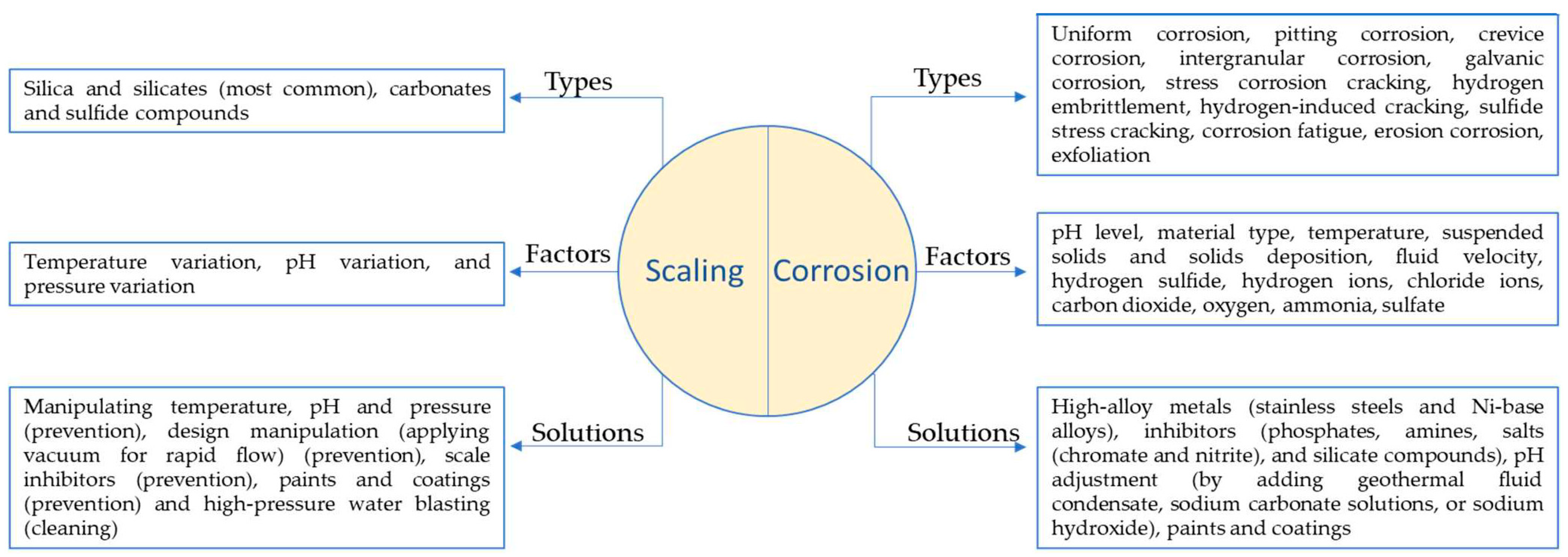
2.1. Challenges

Geothermal environment presents a unique set of challenges, including corrosive nature of geothermal fluids, extreme temperature variations, scaling, and fouling, affecting the efficiency and lifetime of geothermal systems. Figure 2a shows fouling and pitting corrosion observed in the heat exchanger of Büyük Menderes Graben in a geothermal heat exchanger. A detailed discussion about the challenges faced by geothermal heat exchangers is given in the following sections.
  • Fouling
Fouling refers to the unwanted build-up of materials onto the surfaces involved in heat transfer [19,20]. This accumulation, in the form of salts or other deposits, negatively impacts the performance of operational equipment. The process of fouling is affected by a range of factors such as operational conditions, feed composition, heat exchanger geometry, and surface properties. The mechanism of fouling is shown in Figure 2b [21]. The different types of fouling that can occur on the surface of heat exchangers include particulate fouling (accumulation of solid particles on the surface, commonly known as silting), biological fouling (involves the growth or deposition of organisms like bacteria and algae), chemical reaction fouling (involves the formation of solid or viscous layers due to reactions between the fluid and heat transfer surface, such as polymerization), and freezing or solidification fouling (occurs due to the solidification of fluid passing through the heat exchanger at low temperatures). Another form of fouling comprises corrosion fouling, which arises due to the chemical reactions or transportation of corrosion products from other system components and their deposition on heat exchanger surface.
Additionally, the most prevalent form of fouling seen in heat exchanger is the crystallization fouling/precipitation fouling caused by deposits like sulphates (SO42−), carbonates (CO32−) and silicate (SiO44−) of calcium. CO32− and SO42−, due to their retrograde solubility with respect to temperature, are dominant in low-to-medium-enthalpy geothermal fluids, whereas SiO44− is dominant in high-enthalpy geothermal fluids. In the case of heat exchangers, amorphous silica (SiO2) and aluminosilicate are the common deposits, and in some cases, stibnite (Sb2S3) scales have also been reported. These deposits hinder heat transfer due to their low conductivity (0.2–3.0 Wm−1K−1) and decrease the effective cross-sectional area within the heat exchanger tube, leading to the reduced efficiency raising concerns due to decreased flow rate and increased pressure drop [22]. Consequently, this results in increased energy consumption and maintenance costs.
Figure 2. (a) Scaling and pitting corrosion observed in heat exchanger of Büyük Menderes Graben in geothermal heat exchanger, reprinted with permission from Elsevier [11], and (b) mechanism of fouling, reprinted with permission from Elsevier [23].
Coatings 13 01988 g002
The process of deposition of calcium/magnesium from the fluid is often referred to as scaling. Silica scaling, observed in heat exchangers, arises due to the high concentration of silica in the brine solution of geothermal reservoirs. Two major factors governing the rate of silica deposition are the temperature and the pH of brine. Scale deposition increases with an increase in the pH and a decrease in the temperature, mostly occurring in the cooler parts of the plant. However, antimony and arsenic precipitates are mostly seen in geothermal brines at high temperatures [11]. A study conducted on the small tubular heat exchangers of Soultz-sous-forêts by Ledésert, B. A. et al. mentioned the occurrence of PbS (lead sulphide) scaling alongside As and Sb sulphides and halite [24]. One of the impacts of silica scaling includes the roughening of the heat exchanger surface. In the Wairakei geothermal power station, the roughness generated due to silica scales in a shell and tube heat exchanger resulted in a drop in pressure and flow rate, eventually leading to a decrease in the efficiency of the heat exchanger of the ORC [19].
  • Corrosion
Corrosion is another significant challenge that disrupts the proper functioning of geothermal power plants. Factors such as pH, dissolved oxygen levels, temperature, and the presence of corrosive compounds like chlorides, hydrogen sulphides, and carbon dioxide in the brine play an important role in influencing the corrosion process, consequently leading to the failure of components. Various methods are employed to assess the corrosion resistance of coatings, such as autoclave tests, visual examination, and the most common method includes electrochemical assessments. Electrochemical evaluations include open-circuit potential determination, potentiostatic and potentiodynamic (derived Tafel plots are used to determine the corrosion rates), and linear polarisation resistance. The nature of corrosion varies depending on the fluid chemistry of power plants [8] and the differences in the geographical region. The presence of peeling and spalling in coating materials is commonly considered as an indication of corrosion. In a geothermal environment, depending on the materials and components, different types of corrosion are observed, namely uniform corrosion (occurs evenly across a materials surface, typically via the interaction of geothermal fluids with metal surfaces over a long time period), microbial corrosion (occurs as a result of activities of micro-organisms such as bacteria, algae, fungi, etc.), pitting corrosion (observed when there is a breach in the passive layer resulting in the exposure of metal to corrosive surroundings), galvanic corrosion (occurs when two different metals come in contact in an electrolyte and create a galvanic cell), and crevice corrosion (a localized and aggressive form of corrosion that is typically initiated by the trapping of moisture, salts, or other corrosive agents in these tight spaces) are observed. Some other corrosion-related failures include hydrogen embrittlement and stress-induced corrosion. Hydrogen embrittlement occurs due to the diffusion of hydrogen atom into a metal microstructure on exposure of the metal to a hydrogen-containing atmosphere. This makes the material susceptible to cracking by reducing its ductility and eventually results in the failure of the component. If this phenomenon occurs in an environment having a high content of H2S (hydrogen sulphide) and is followed by failure of the material owing to stress, it is known as sulphide stress cracking [25,26]. Morake, J B et al. identified hydrogen-induced cracking and sulphide-induced stress corrosion cracking as the cause behind the failure of CuNi10Fe (cupronickel) tubes in a shell-and-tube heat exchanger. The exchanger tubes operated for five months within a temperature range of 144 °C to 27 °C and at a pressure of 2.0 bar. Erosion was observed in the cupronickel layer and it was facilitated by high pressure, which allowed hydrogen entry into the tubes. Additionally, the H2S environment contributed to hydrogen ingress, leading to sulphide stress corrosion cracking in these tubes [27]. Mundhenk, M. et al. performed in situ and laboratory-based corrosion tests on various mild steels (API N80, API P110, P235GH, and P265GH), stainless steels (430 F, 316 L), alloy 904 L, duplex alloy 318 L, super-duplex alloy 31, nickel-base alloys 59, 625, and titanium grade 2. All metals were analysed in a Soultz geothermal brine environment in order to obtain a better understanding of corrosion and scaling in the Soultz-sous-Forêts geothermal power plant, France. The corrosion tests were performed through autoclave testing using the weight loss method at three temperatures: 20 °C, 80 °C, and 160 °C. In their findings, the authors observed that mild steel displayed uniform corrosion and localised corrosion, specifically, pitting and filiform corrosion. Moreover, it exhibited long-term uniform corrosion rates, lower than 0.2 mm/year at a temperature of 20 °C, and the highest corrosion rate was observed at a temperature of 80 °C (Figure 3). Corrosion was coupled with the formation of a dense and adherent scale that led to the protection of substrate. Pitting corrosion is observed in stainless steels 430 F and 316 L, and the authors rendered them as an unsuitable candidate for utilization in Upper Rhine valley geothermal environments. Higher-alloyed materials demonstrated a high resistance against uniform corrosion and portrayed corrosion rates of <0.005 mm/year, and the authors identified these to be suitable for geothermal service [28].
In the ORC binary plant, corrosion is observed in different heat exchanger components such as tubes and channels due to their contact with the aggressive geothermal fluid. Thus, materials like stainless steel, titanium, and duplex steels are preferred over the carbon steel for construction of such components [8,29]. Faes, W. et al. have given a detailed discussion on the failure of heat exchangers due to corrosion [29]. The practice of subjecting materials to the actual conditions of geothermal environment provides a means to evaluate the response of the materials towards the extreme conditions of the geothermal fluids and to predict the longevity and suitability of these materials. Various studies have relied on this; for instance, Davíðsdóttir, S. et al. investigated the local corrosion of four different heat exchanger materials (316L, 254 SMO, Inconel 625, Titanium grade 2) in two different high saline geothermal plants: Reykjanes, Iceland: 200 °C and 18 bar vapour; Chaunoy, France: 94 °C and 9.5 bar fluid (Figure 4) [30]. Their results revealed subsurface cracks and Cu deposits on Ti grade 2 in Reykjanes, whereas in Chaunoy, the corrosion products were rich in Fe and S. Erosion was also observed in the Ti grade 2 used in both sites. The 254 SMO exposed in both sites showed subsurface cracks, and in Reykjanes, pitting corrosion was also observed. Two corrosion layers were formed on the 316L exposed surface in Reykjanes, and local corrosion was observed in Chaunoy. The differences observed are mainly due to pH differences in both the plants. The corrosion products were of Fe, O, and Cr and a trace of Al in Chaunoy. The Inconel 625 showed no evidence of corrosion on the surface exposed in Reykjanes but showed subsurface cracks after exposure [30].
Figure 5 shows different forms of corrosion and scaling and the factors that can accelerate these phenomena. Moreover, it includes a brief mention of some of the effective solutions.

2.2. Effective Solutions

The issues outlined above limit the effectiveness of the heat exchanger, raise capital, operating, and maintenance expenses, and also give rise to safety concerns. As a result, ensuring optimal heat exchanger performance has prompted extensive research into developing effective strategies for tackling fouling and corrosion. Research has shown that the design phase of the heat exchangers plays a crucial role in mitigating fouling [31]. This involves considering factors such as shape, geometry, operating conditions, and ease of cleaning. Various studies have utilized chemical and mechanical techniques to mitigate the corrosion and fouling of components in geothermal environment. Chemical inhibitors, both organic and inorganic, with poly functionality such as phosphates, phosphonates, and carboxylates, are widely used in heat exchangers of complex geometries for mitigating fouling [32,33,34]. Scheiber, J. et al. [35] studied the scaling inhibition in Soultz-sous-Forêts by a phosphonate-based inhibitor against Sr and Ba deposits. However, these inhibitors negatively impact the environment, and their stability is temperature-dependent [11]. Furthermore, the applications of these inhibitors developed for ionic solids becomes challenging when dealing with covalent compounds like silica, which affects the efficiency and selectivity of them [36]. Cho, Y. and B. G. Choi have used the electronic anti-fouling (EAF) technique in order to mitigate fouling in heat exchangers [37]. Mechanical techniques, such as laser machining and electrical discharge machining (EDM), are employed for creating anti-fouling surfaces, but they tend to be relatively costly and less efficient. Both EDM and magnetron sputtering have been applied to create C-films on Cu substrates, resulting in elevated water contact angles [38]. A simple and relatively cheap method of fabricating superhydrophobic surface using CaCO3 self-assembled coatings modified by sodium stearate in simulated geothermal water has been investigated by Wang, G. G. et al. These coatings were found to have a contact angle of 158.9 °C after 48 h of immersion in geothermal water [39]. There is research that has explored the substitution of CO2 for acid additions and found it to be effective in regulating pH and managing scale inhibition [36].
Even though Ti alloys and stainless steels are used in various components of geothermal plants, due to the passive layer providing resistance to corrosion and scaling. The interaction of silicate, silica, and calcite present in the solution with the surface oxide layer of these materials results in the increased adhesion of these compounds, thus reducing the efficiency of the geothermal component. These also react with the chloride ions, causing corrosion of the components [40]. In addition, compared to carbon steel, these are expensive; for instance, stainless steel AISI 316 costs EUR 3480, and AISI 306 costs EUR 2900 per tonne, whereas carbon steel has a cost of EUR 900 per tonne [41]. Hence, it could be more cost-effective to apply a compatible protective coating to carbon steel, rendering it suitable for use in geothermal heat exchangers, rather than opting for more expensive stainless steels. The selection of a coating and its performance for any substrate depends on the coating materials and its microstructure. And of all the employed methods, surface modification through coatings emerges as an exceptionally efficient and economically viable approach to address challenges within geothermal heat exchangers; for example, Figure 6 provides a clear illustration of the impact of coatings on fouling rates, highlighting the significance of coatings. It is therefore found to be necessary to review the coating techniques and the coatings which are used for the geothermal environment.
In recent times, high-entropy alloys have gained significant attention for applications in geothermal environments. A study led by Thorhallsson, A. I. et al. at the Hellisheidi geothermal site explored the use of CoCrFeNiMo(0.85) and Al(0.5)CoCrFeNi high-entropy alloy coatings through laser melt deposition on the C-steel [S3257R] and stainless steel [316L]. Notably, the former alloy exhibited superior erosion–corrosion resistance compared to the latter in the geothermal environment [42]. Geambazu, L. E. et al. found that the electro-spark deposited CoCrFeNiMo(0.85) performed well in a geothermal environment, and the rate of corrosion of the coated 316L stainless steel substrate in 3.5 wt% NaCl was 0.00016 mm/year [43]. Oppong Boakye, G. et al. conducted examinations into CoCrFeNiMox (x = 20% and 27%)-coated surfaces, employing laser cladding, high-velocity oxy-fuel (HVOF), and electro-spark deposition techniques, for potential application in geothermal environments [44].

3. Coating Technologies for Geothermal Heat Exchangers

There are different coating methods that can be used to develop coatings especially for geothermal heat exchangers, aiming to enhance the resistance to corrosion, erosion, scaling, and fouling. The choice of coating material and method is determined by the specific requirements that are affected by geothermal fluid composition, temperature, pressure, and type of geothermal heat exchanger. Potential coating techniques for geothermal heat exchangers are mentioned in the following sections.

3.1. Coating Methods

3.1.1. Thermal Spray

Thermal spray stands as a long-established technique utilized for depositing an extensive array of materials onto diverse components, serving various applications such as biomedical, electronics, and aerospace sectors [42]. Thermally sprayed coatings, characterized by their ease of application, compact structures, and strong adhesive strength, are used for protection against corrosion, wear, erosion, thermal degradation, and oxidation. In comparison to other coating methods, thermal spraying offers several benefits including high production efficiency, durability, and cost-effectiveness [43]. Commonly employed thermal spray methods include plasma spray, high-velocity oxy-fuel (HVOF), flame spray, and arc-spray deposition. In the thermal spray deposition process, the coating material is either fully or partially melted by a heat source and propelled by gases towards the substrate. On impacting the substrate or previously deposited particles, the molten or semi-molten consumable spreads, cools, and forms ‘pancake-shaped’ splats. These splats build up and form the coating. The deposited coating is impacted by kinetic and thermal energy profiles of feedstock droplets traveling towards the substrate during deposition [45].
Plasma spray and HVOF processes are favoured over other thermal spray techniques due to their superior coating quality and versatility in terms of feedstock. Both of these methods allow the use of feed (coating materials) in either powder or liquid/suspension form [42,45]. Liquid feedstock is sometimes preferred over powder feedstock due to various reasons: (a) abstaining from the usage of particles smaller than 10 μm in size in powder feedstock as such particles lack the necessary momentum to be fed into the system; (b) nozzle clogging can result from the accumulation of dry powder feedstock [42]. As a result, coating materials that are suspended or dissolved in a solvent are sometimes preferred over powder feedstock. However, obtaining such feedstock commercially can be challenging.
Liquid feedstock involves submicron or nanosized particles suspended within a liquid medium leading to multiscale features in deposited coatings [46]. Both plasma spray and HVOF spray processes utilise thermo-chemical interactions (in the case of solution precursor feedstock) and thermo-physical interactions between the feedstock and plasma. However, coatings deposited through each method exhibit distinct characteristics depending on the difference in generated heat and velocity. Coatings deposited using HVOF method tend to be denser and smoother compared to plasma spray coatings. Conversely, plasma spray generates more heat, facilitating the melting of high-temperature consumables such as zirconia (ZrO2) or alumina (Al2O3) [45,47]. In addition to the deposition methods, coating quality is also influenced by other spray parameters, namely the heat source, feedstock flowrate, standoff distance (SOD), suspension medium, fuel type (for HVOF), and injection mode (radial or axial) [45,48,49]. Buzaianu, A. et al. employed the HVOF technique to deposit Ni20Cr10Al2Y coatings to improve erosion corrosion properties of carbon steel for geothermal environments [50]. In another study, Zhang, F. et al. utilised liquid feedstock-based HVOF to deposit various cermet (WC-CoCr and CrC-NiCr) and other alloys (Ni self-fluxing, and Fe-based amorphous), and examined their erosion–corrosion performance in geothermal environments. The SEM images of these coatings after 24 h immersion in a simulated geothermal environment are shown in Figure 7, and there was no sign of corrosion product formation for WC-CoCr and CrC-NiCr cermet, and Ni self-fluxing coatings due to the uniform microstructures of coatings with a low volume fraction of fine pores and non-interconnected voids. Fe-based amorphous coatings demonstrated the presence of interconnected defects, including cracks and voids, which favoured the permeation of electrolyte into these defects. Thus, these coatings showed accelerated corrosion and corrosion-induced delamination of the coating [43]. Azarmi, F. et al. deposited titanium dioxide/titania (TiO2) coatings using suspension-based plasma spray (SPS) and suspension-based HVOF spray (S-HVOF) to explore the effects of standoff distance (for plasma spray) and fuel gas (for HVOF spray) on coating properties and microstructures. It was shown that increase in the standoff distance leads to a reduction in the amount of suspension-transported material in the coating. Moreover, it was also established that the coating formation is dependent on the pre-heating and deposition temperatures [45].

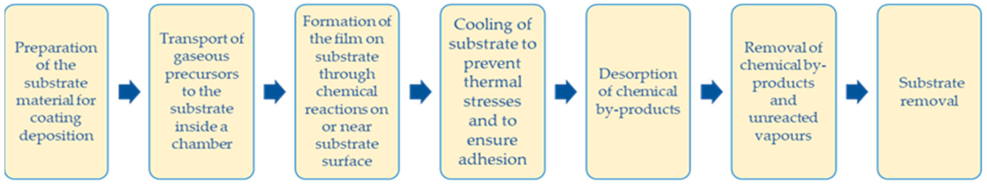
3.1.2. Chemical Vapor Deposition (CVD)

The process of CVD (Figure 8) entails the disintegration and/or chemical reaction of gaseous reactants within an activated environment (such as heat, plasma, or light) to yield dense thin films with elevated purity and performance [23]. Fundamental chemical reaction types within the realm of CVD encompass pyrolysis (thermal decomposition), oxidation, reduction, hydrolysis, formation of nitrides and carbides, synthesis reactions, disproportionation, and chemical transport. In more complex scenarios, a combination of these reaction types might be implicated to generate a specific final product. The deposition rate and characteristics of the deposited film are dictated by deposition parameters such as temperature, pressure, reactor geometry, input concentrations, gas flow rates, and operational principles [51]. CVD process can produce thin-films inclusive of a vast array of elements and compounds. These materials encompass inorganic, organometallic, and organic reactants as starting substances. The thermally activated CVD process is a conventional CVD approach which utilises thermal energy for initiating chemical reactions and is most commonly employed for depositing thin films of transition metal nitrides. Based on the pressure range under which deposition occurs, thermally activated CVD can be categorised into atmospheric pressure CVD (APCVD), low-pressure CVD (LPCVD) having a pressure range of 0.01–1.33 kPa, or ultra-high-vacuum CVD (UHVCVD) comprising a pressure of <10−4 kPa [23,51]. The sole distinction between APCVD and LPCVD is that the reduced pressure modifies the rate-controlling step during the deposition reaction. Thus, LPCVD processes are generally limited by the rate of surface reaction, whereas APCVD processes have the restriction of mass transport or diffusion rates. One of the drawbacks of CVD is that the gaseous by-products produced in this process are usually quite toxic [52]. CVD epitaxy, atomic layer deposition (ALD), plasma-enhanced CVD (PECVD), photo-enhanced CVD (PHCVD) laser-assisted or laser-induced CVD (LACVD), metal-organic CVD (MOCVD) and electron enhanced CVD include some other CVD methods [51,53]. Preston, D.J. et al. demonstrated the effectiveness of graphene coatings deposited through the CVD technique in promoting the dropwise condensation effect of water. The graphene coatings were deposited by LP-CVD and AP-CVD, and they exhibited an enhanced heat transfer and better chemical stability compared to contemporary coatings produced using other techniques. These coatings could be potential candidates to be applied in a geothermal environment [54].

3.1.3. Physical Vapor Deposition (PVD)

The process of PVD involves the deposition of thin layers of various materials onto a substrate in the presence of a vacuum, serving to either enhance the material’s functionality or to confer thermal and/or chemical stability [55]. Metal oxides are vaporised through physical means like cathodic arc deposition, electron beam PVD (EB-PVD), evaporative deposition, pulsed laser deposition, sputter deposition, or sublimation [56]. PVD coatings are applied to enhance surface properties such as hardness, wear resistance, corrosion resistance [55] and protection against fouling [23]. This process has the advantage of tailoring the composition with high precision and permitting thin films to be deposited at lower temperatures compared to other techniques such as CVD, which is important when the substrate being coated with is a temperature-sensitive material [56]. EB-PVD, a high-vacuum thermal coating process, is considered to be a simple and relatively cheaper technique as compared to some other deposition processes, including ionic sputtering of a target source, ionic bombardment of the particles by ion beam-assisted deposition (IBAD), and pulsed laser evaporation technique [57]. Other advantages of EB-PVD include high deposition purity, enlarged coating area, precise film thickness, in situ growth monitoring, and smoothness control [58]. However, limitations of PVD processes include the requirement of a large vacuum chamber making it a high-cost process, the sensitivity of deposited materials to the orientation of substrate resulting in epitaxial stresses and strains which lead to variations in film properties across a large substrate, thus making it incompatible for large-scale production. PVD methods also have a relatively slower deposition rate compared to CVD [53,59]. Oon, C.S. et al. employed PVD magnetron sputtering to deposit a titanium coating (selected because of its high corrosion resistance and surface adhesion) on a stainless steel SS316L heat exchanger. Ti-coated SS316L demonstrated a decrease in calcium carbonate-related fouling caused by the deposition of 201 mg/L of deposits, whereas the uncoated specimen displayed 269 mg/l of deposits on its surface. Moreover, Ti coating also revealed an enhancement in the average heat transfer coefficient with an increase in the Reynold number (Re, the ratio of inertial to viscous forces within a fluid). This was observed at Re 3803 and Re 15,212 [23]. In another body of research, Ali, N. et al. established that combining an EB-PVD coating and the modification of brine parameters is a promising approach for altering the degree of wettability of copper surface, leading to the enhancement in heat transfer efficiency (via improvement in critical heat flux and fluid dynamics) of plate heat exchangers. These authors produced copper films on a copper substrate through EB-PVD and showed that the thickness of the film/coating, pH of the liquid (water), and the surface roughness caused by the deposited film affect the wettability behaviour. It was demonstrated that an increase in the pH value led to a reduction in the average contact angle (ACA) of water. This was attributed to the enhancement in the surface energy of the substrate due to the deposited film. This had led to a reduction in both the surface micro-roughness and formation of air pockets between the liquid and substrate interface. Moreover, an increase in the film thickness also resulted in a decrease in the surface roughness of the copper surfaces, thus leading to a deviation in the surface wettability from a hydrophobic nature to a hydrophilic nature [60].

3.1.4. Liquid Phase Deposition (LPD)

The LPD is a wet-chemical method based on the controlled hydrolysis of metallic fluoro-complexes. This aqueous technique is utilized for the deposition of oxide films, and it demonstrates various advantages such as the utilization of low-energy-cost equipment and partially crystalline products at ambient temperatures [61,62,63,64,65]. Additionally, it facilitates good control over deposition rates and crystal orientations [62]. LPD has found significant application with materials like TiO2 [62,66,67,68,69,70], SiO2 [70,71], etc. A study by Zhang, F. et al. demonstrated a significant reduction in fouling resistance (an increase in the resistance to the flow of heat (m2KW−1) due to fouling) of LPD TiO2-FPS (FPS—heptadecafluorodecyltri-isopropoxysilane)-coated stainless steel plates in comparison to the uncoated stainless steel samples. The LPD TiO2-FPS coating exhibited an asymptotic fouling resistance of 1.2 × 10⁻⁵ m2KW−1, whereas the untreated SS plates maintain a higher fouling resistance of 3.3 × 10⁻⁵ m2KW−1 for an experimental duration of around 12 days. Moreover, the LPD TiO2-FPS coating plates demonstrated a threefold extension in the fouling induction period, lasting for approximately 10 days compared to the untreated SS plates. This was attributed to the flow rate of fluid. It was concluded that higher flow rates result in higher heat transfer coefficient, thus reducing fouling [72]. In another work, LPD TiO2 coatings on stainless steel substrate were investigated for anti-fouling performance in hot-dry-rock (HDR) geothermal water, containing 7 g/L of total dissolved solids, at 423 K. These coatings displayed a fouling resistance of 2.20 × 10⁻⁴ m2KW−1 and the heat transfer coefficient obtained was 900 Wm−2K−1. These results were obtained after an experimental period of around six days. Moreover, the authors observed that at an experimental time of 20 h, the heat transfer coefficient was 955 Wm−2K−1, which was similar to that observed in sol–gel TiO2 coatings deposited under same conditions. However, the fouling resistance of LPD TiO2 coatings was 30% higher than the sol–gel TiO2 coatings due to higher heat transfer coefficient of LPD coatings. SEM morphology of TiO2 coatings deposited on stainless steel substrate, SS 304, using LPD and the sol–gel method is shown in Figure 9 [70].

3.1.5. Sol–Gel Method

The sol–gel method is a versatile approach for the formulation of inorganic or hybrid coatings, with applicability through various procedures like dipping, spraying, or spinning [73]. This method offers numerous advantages, including low deposition temperature, production of homogenous coatings, and good control over both metal concentration and coating thickness, and permits the addition of reducing and oxidizing agents in small quantities [74]. Additionally, the sol–gel process requires simpler coating equipment [72]. Song, J. et al. deposited sol–gel TiO2, SiO2, and SiO2-FPS coatings on stainless steel (AISI 304) tubes and examined their anti-fouling and anti-corrosion behaviour in a simulated HDR geothermal water at around 423 K. The findings indicated that the sol–gel TiO2 coatings exhibited excellent anti-fouling characteristics when exposed to simulated geothermal water with a calcium bicarbonate composition. Meanwhile, the sol–gel SiO2 and SiO2-FPS coatings demonstrated superior antifouling and anti-corrosion properties when tested in moderately corrosive HDR geothermal water with a total dissolved solids (TDS) concentration of approximately 7 g/L. In comparison to SS304 tubes, sol–gel TiO2-coated heat exchanger tubes exhibited a fouling resistance reduction of more than 48%, whereas sol–gel SiO2 and SiO2-FPS demonstrated a fouling resistance reduction of 30% and 58%, respectively, in their study. Moreover, electrochemical corrosion tests conducted on these coatings and on SS304 specimens for 14 days reveal that both coatings, compared to SS304, can reduce the corrosion rate by 60.1% and 85.2%, respectively [70]. Schulz et al. [75] and Nofz et al. [76] highlighted the protective nature of Al2O3 sol–gel coatings in environments characterized by high-temperature flue gas and the presence of NaCl, respectively. Since, geothermal environments often exhibit elevated temperatures and salinity levels, Aristia, G. et al. explored the potential application of Al2O3 sol–gel coating for safeguarding martensitic steels in such geothermal conditions and concluded that these coatings offered a bright future in providing corrosion protection in geothermal environments with a neutral pH [73]. Zhang, F. et al. performed experiments to observe anti-fouling on silica- and titania-coated plate heat exchangers in 80 °C simulated geothermal water. They coated stainless steel (AISI 304) substrates with TiO2, TiO2-FPS, SiO2, and SiO2-FPS coatings, and from their findings, they concluded that SiO2 and SiO2-FPS sol–gel coatings were not appropriate for anti-fouling in geothermal water. However, the combination of these coatings with mechanical cleaning results in good fouling and corrosion resistance in geothermal water. Additionally, corrosion was observed on both TiO2 and TiO2-FPS coatings, and the fouling induction period for these coatings only extended to 50 h, after which no fouling resistance was perceived. The authors concluded that fouling deposition can be reduced via the utilisation of surface engineering technology on heat exchanger plates [72].

3.1.6. Electroless Plating Method

Electroless plating is a type of surface treatment in which a thin layer of metals, salts or other compound is plated without the use of external power. This electroless deposition occurs as a result of a redox reaction between the metal and the reducing agent, e.g., hypophosphite, leading to the reduction and subsequent deposition of metallic ions on the surface [77,78,79,80,81]. The wide application of electroless plating is due to the uniformity regardless of the shapes and size of the surface, low porosity and roughness, high adhesion of these coatings to the substrate, and the excellent corrosion, wear, and abrasion and fouling resistance [81,82]. Cheng, Y. et al. investigated the anti-fouling properties of Ni-P electroless plating on low-carbon steel under various operating conditions. The immersion tests in boiling water and cooling using tap water containing Ca ions, revealed that the coated low-carbon steel exhibited less surface fouling deposition compared to the uncoated stainless steel substrate. However, there is no mention of whether tap water has been used for the immersion testing. Furthermore, after 20 h of immersion, they observed loose and discontinuous fouling on the coated surface, in contrast to the uncoated stainless steel. Notably, the rate of fouling appeared to increase with a higher proportion of nanocrystalline phase in the electroless plating; surfaces with 92 mass % of nanocrystalline phase were less resistant to fouling than those with 17 mass % and 5 mass %. From this observation, they concluded that the structural inhomogeneity of nanostructures, the presence of number of grain boundaries in the nanocrystalline structure, promotes the formation of numerous electrochemical cells, resulting in the acceleration of corrosion and fouling when compared to amorphous structures. However, it is important to note that the study did not address the heat transfer performance of the plated surfaces [83]. The same authors conducted a subsequent study on electroless Ni-Cu-P plating on AISI 1015, with a coating thickness within the range of 12–16 µm. They observed that the adhesion strength between the coating and the substrate exhibited an increase corresponding to higher copper concentrations, ranging from 2.97 wt.% to 13.78 wt.%. In addition, all the coatings displayed effective anti-fouling properties when compared to the uncoated stainless steel. The water contact angle exceeded 90° for all samples containing copper. Notably, the contact angle exhibited an initial increase with the rise in CuSO4 content up to 0.4 g/L, followed by a decrease.
Conversely, surface energy displayed an increasing trend, reaching a maximum at 26.56 MJ/m², but a further increase in copper concentration resulted in decreased surface energy. The coating with the highest copper content demonstrated the least resistance to fouling. The study provided conclusive evidence that the addition and amount of Cu plays a significat role in the fouling deposition rate, contact angle, and surface energy of the coated surface [84]. Following these results, the authors investigated the introduction of varying concentrations of Polytetrafluoroethylene (PTFE) particles (4, 8, 12, 16 mL/L, denoted as Samples 1, 2, 3, and 4) into electroless Ni-Cu-P coatings on mild steel. The surface morphology of electroless Ni-Cu-P-PTFE after 2 h of deposition is given in Figure 10, showing the homogenous distribution of PTFE particle (black spots) in the matrix. They observed that when compared to the uncoated mild steel surface, the anti-fouling rate was notably reduced on the coated surface. Moreover, the contact angle and surface free energy were found to be dependent on the PTFE concentration. Specifically, the surface free energy decreased with increasing PTFE particle content, ranking as Sample 3 < 4 < 2 < 1, while the contact angle displayed a reverse trend as expected. Furthermore, fouling experiments revealed that the surface with the lowest surface energy exhibited the weakest adhesion of deposits. However, it is worth noting that the addition of PTFE particles had no effect on surface roughness, but it led to a reduction in the surface’s microhardness [85]. In the study conducted by Oppong Boakye, G. et al. on the Electroless Ni-P + PTFE composite duplex coatings, the authors investigated for the wear and abrasion resistance. The study revealed that the coating with a medium PTFE content of 10 g/L exhibited superior wear and abrasion resistance. Notably, the coating with a medium PTFE achieved the highest water contact angle of 102.6°, compared to coatings with low and high PTFE contents. The findings suggest that this specific coating composition, with its enhanced properties, holds potential for application in heat exchangers [86].

3.1.7. Weld Overlay

Weld overlay, also known as weld cladding, involves welding a material onto the base metal to provide protection against corrosion, erosion, and high temperatures. This process utilizes techniques such as arc welding and electron beam welding, and laser cladding [87,88,89]. In order to enhance the corrosion–erosion of the turbine-rotor, weld overlaying of Inconel 625 has been adapted in [90]. Tayactac, R. G. and E. B. Ang conducted a comprehensive review of various alloys for their suitability as corrosion-resistant alloy (CRA) cladding in wellhead piping systems operating in geothermal environments. Their analysis revealed that alloy 625 emerges as a highly advantageous choice for CRA cladding in geothermal power plants [91]. Currently, there is no published research article in public domain mentioning the utilization of weld overlay in geothermal heat exchangers.
A comparison of advantages and disadvantages of various coating technique is summarized in Table 2. It should be noted that not many research articles are published focusing on the coatings for geothermal heat exchangers. But the sectors where coatings are used to protect their components against harsh conditions might be useful for geothermal environments.

3.2. Coating Materials and Performance

As coatings are vital for the prolonged service life and enhancement of heat exchanger efficiency, the research on coatings for heat exchanger has attracted significant attention among researchers in the geothermal sector. It is therefore imperative to understand the commonly employed coatings that are used in heat exchangers and their performance, and the types of technology that have been used to apply these coatings. Table 3 demonstrates various coatings used in a geothermal environment along with their deposition techniques and impacts. Commonly used coatings for geothermal applications include metallic, inorganic, and organic coatings. The organic coatings that have undergone the most comprehensive research within geothermal heat exchangers are predominantly polymer coatings. As indicated by [13], coatings consisting of single or multiple layers of polymer materials fall under the classification of paints (in contrast to the layer of metals, ceramics, or their combination, which is referred to as ‘coatings’ in this review paper). In consideration of geothermal heat exchangers, various commonly researched types of paints include epoxy, fluoropolymer, phenol-based polymer, polyphenylene sulphide polymer, organometallic polymer, and polyamide polymer. These are applied to the surface mainly via the fill-drain-baking or dipping-baking technique. Five coating types were employed for the study conducted by Losada, R. et al.: two fluoropolymer (F1 and F2) -based coatings, a phenol (Ph)-based coating, and two variants of epoxy-based coatings (EP1 and EP2). EP1 comprised four layers: a zinc-rich epoxy primer as the first layer, followed by two layers of amine-cured epoxy coatings, and concluding with a fourth layer of hybrid organic or inorganic sol–gel coatings. On the other hand, EP2 lacked the zinc-rich epoxy primer in its initial layer. These coatings were applied to both carbon steel (P265G) and stainless steel (AISI 316L) substrates. Subsequently, the coated samples underwent testing in a specially designed autoclave system immersed in a brine similar to that found in Balmatt, containing 165 g/L of dissolved solids predominantly composed of sodium and chloride, for a duration of 24 days. Post-exposure, evaluations were conducted, encompassing visual inspections, adhesion assessments, and electrochemical impedance spectroscopy (EIS) tests. Notably, both fluoropolymer-based coatings (F1 and F2) exhibited blistering and failed adhesion tests when applied to carbon steel surfaces. Conversely, the phenol-based and epoxy-based coatings displayed exceptional adhesion properties, devoid of blistering. Moreover, on stainless steel substrates, all coatings exhibited strong adhesion and remained free from blisters. Following the EIS tests, three coatings—F2 on stainless steel, EP1 on carbon steel, and EP2 on stainless steel—demonstrated excellent resistance to electrolyte penetration. Consequently, these were selected for further analysis regarding thermal resistance and conductivity. The thermal conductivity ranking among these coatings was observed as F2 < EP2 < EP1, measuring 0.25, 0.58, and 0.63 WmK−1, respectively. Notably, both F2 and EP1 exhibited an identical thermal resistance of 0.0004 m2K/W, whereas EP2 recorded a slightly lower thermal resistance of 0.00025 m2KW−1. The researchers concluded that these selected coatings exhibited improved corrosion resistance, but no significant impact on heat transfer resistance were observed. Additionally, these coatings displayed favourable surface properties, such as smoothness and low surface energy. However, they recommend conducting further comprehensive tests to assess the coatings’ performance under real-world conditions [98]. Sugama. T. et al. investigated the application of PPS (polyphenylene sulphide)- and PTFE (polytetrafluoroethylene)-blended PPS coatings on AISI 1008 carbon steel in their study. The coatings were deposited via fill-drain-baking techniques. Sodium metasilicate dissolved brine at 200 °C were used for the study in order to evaluate the coatings behaviour towards silica scaling. SEM/EDX and XPS analyses were carried out to characterize the coatings post-immersion tests spanning 1, 3, and 7 days, with a comparison to the uncoated substrate. Figure 11 below displays SEM images of the bare steel substrate, PPS-coated steel surface, and PTFE-blended PPS-coated surface after 7 days of immersion. The bare C-steel exposed to brine exhibited a well-crystallized silica layer on the surface, identified through XPS as the crystobalite phase (SiO2). The PPS-coated surface appeared smooth, suggesting the absence of micro-scale silica on the bulk PPS-coated surface. However, EDX analysis on the rinsed surface revealed a certain amount of silica. In contrast, the PTFE-blended PPS exhibited a rough surface texture due to PTFE incorporation, and no Si peaks were detected in the EDX analysis, indicating the inertness of these coatings towards silica scaling [99].
Another study conducted by the same author studied PPS coatings system on a carbon steel (AISI 1008) heat exchanger tube. Two types of coating systems, one with a Zn-Ph primer with an intermediate layer of a SiC-filled polymer and a top layer of PTFE-blended PPS and the other with Zn-Ph primer with ACA (aluminium oxide-rich calcium aluminate filled PPS) and a reference material of stainless steel (AL-6XN) were exposed to geothermal brine for 11 months at 160 °C. The fill-drain-baking technique was used to deposit these coatings, with the thickness ranging from 300 to 330 μm on the C-Steel. Different characterisation techniques included SEM/EDX analysis for determining the microstructure of the liner as well as for investigating the morphology of the deposited products, FT-IR (Fourier transform infrared) results, XPS (X-ray photoelectron spectroscopy) analysis for investigating the chemical composition and state change, and DSC (differential scanning calorimetry) analysis for evaluating the change in thermal properties. Based on the findings, the authors determined that the PTFE-infused PPS coating effectively lowered hydrothermal oxidation and scale deposition rates as anticipated. Moreover, it facilitated the easy removal of scales through hydro blasting and demonstrated substantial resistance to brine permeation. Conversely, the surface treated with an ACA-filled PPS coating experienced oxidation, and silica scale deposition was evident. However, despite these issues, the coating proved to be corrosion-resistant, as no brine-related elements were detected on its surface [100]. Sugama, T. et al. utilised Ce2O3-filled-PAAMPA (poly-acetamide-acetoxyl methyl-propylsiloxane), Ce(OH)3-filled-PAAMPA composite coatings and polyaminopropylsiloxane (PAPS) polymer coatings for corrosion protection of carbon steel and aluminium substrates. These coatings were prepared using dipping-withdrawing-baking technique at a baking temperature of 150 °C and 200 °C. SEM analysis of the organometallic polymer coatings demonstrated a smooth and continuous fissure-free morphology. Additionally, Ce2O3/PAAMPA coating provided better corrosion protection to the C-steel substrate than Ce(OH)3/PAAMPA and PAPS coatings. Tafel analyses were carried out using 5 wt% NaCl solution at 35 °C in accordance with ASTM B117. From the results, it was observed that Ce2O3/PAAMPA coatings on the steel substrate revealed a corrosion rate and a corrosion current (Icorr) value of 1.064 mpy (milli-inches per year) and 2.329 × 10⁻⁶ A·cm−2, respectively, whereas bare carbon steel substrate demonstrated a corrosion rate of 5.257 mpy and an Icorr value of 1.150 × 10⁻⁵ A·cm−2. PAPS coating on steel exhibited a corrosion rate of 3.714 mpy and Icorr of 8.125 × 10⁻⁶ A·cm−2. Also, bare aluminium substrate, Ce2O3/PAAMPA-coated aluminium panels, and PAPS-coated aluminium panels showed a corrosion rate of 1.8 × 10⁻¹ mpy, 4.9 × 10⁻³ mpy, and 6.8 × 10⁻² mpy, respectively. The authors attributed the improved performance of organometallic coatings to the better coverage attained, which prevented electrolytes from moving through the coating, and also to the hinderance in the cathodic oxygen reduction reaction resulting from the formation of interfacial passive Ce2O3/PAAMPA film on the substrate. Moreover, this film also reduced the susceptibility of coating’s surface to moisture [101]. In another study, a thin water-based organo-metallic polymer (OMP) coating was used to mitigate corrosion and scaling issues for steel tubes with helically wound aluminium fins heat exchangers. The uncoated samples were exposed to geothermal fluid at Mammoth Lake binary plant for approximately one month. From the SEM analysis, the authors observed a notably rough surface texture, indicating localized pitting corrosion. Furthermore, scale deposits of around 2 µm in thickness were also observed on aluminium fins. An EDX analysis of these scales revealed that they comprised silica-rich compounds containing calcium, magnesium, and iron oxides. These scales also demonstrated strong adhesion to aluminium surfaces making their removal a difficult task. The OMP-coated aluminium fin samples were analysed for protection against corrosion and adhesion of scale on the fin surfaces. The OMP-coated and uncoated samples were analysed for corrosion for 30 days using 5 wt% NaCl solution in accordance with ASTM B117. The thickness of these polymer coatings was ~10 µm. From their findings, the authors identified OMP coatings as suitable candidates for protection against corrosion and scaling [102].
Azarmi, F. et al. deposited TiO2 coatings on a carbon steel (S275JR, EN 10025-2) substrate using suspension plasma spray (SPS) and suspension high velocity oxy-fuel spray (S-HVOF) as the deposition technique. SPS-based TiO2 coatings were deposited at a standoff distance of 50 mm, i.e., Ti-50, and 80 mm, i.e., Ti-80, whereas the varying parameter in S-HVOF-based coatings was the fuel type used, hydrogen fuel, i.e., Ti-H, and propylene fuel, i.e., Ti-P. The authors analysed the morphology of the coating surface using scanning electron microscope (SEM). Both SPS-based and S-HVOF-based TiO2 coatings exhibited characteristic cauliflower-like morphology resulting from the piling of molten, semi-molten, and re-solidified particles on the substrate. However, the authors perceived that HVOF-deposited coatings were smoother and denser than those prepared through the SPS method. This was attributed to the higher impact velocity of the particles which resulted in better adherence of molten and/or semi-molten particles to the substrate. The authors compared the wettability of all samples through water and diiodomethane contact angle measurements. The water contact angles observed for Ti-50, Ti-80, Ti-H, and Ti-P coatings were 17.58°, 19.47°, 115.77°, and 105.8°, respectively, whereas, the diiodomethane contact angles for Ti-50, Ti-80, Ti-H, and Ti-P coatings were <10°, <10°, 53.31°, and 50.54°, respectively [45]. In another work, Song, J. et al. deposited TiO2, SiO2, and SiO2-FPS coatings on a stainless steel (AISI 304) substrate using the sol–gel method, and another set of TiO2 coatings were deposited through the LPD technique. Figure 12 reveals the surface morphology of all coatings; Figure 12a,b reveal a relatively smooth surface morphology of the sol–gel TiO2 coating on a polished SS304 substrate. A high degree of homogeneity can be observed at a higher magnification, 50 kX (Figure 12b), with neat and tight arrangement of TiO2 nanoparticles having a diameter of approx. 50 nm. Figure 12c,d show SEM images of a sol–gel SiO2 coating; this coating exhibited a rougher surface compared to the TiO2 coating. The sol–gel SiO2 coating displayed multilayer stacking of SiO2 particles and the existence of irregular pore defects having a diameter range of 10–200nm. Figure 12e–h display SEM images of an LPD TiO2 coating and a sol–gel SiO2-FPS composite coating at 5 kX and 50 kX, respectively. Long nano-meter-wide cracks and round nanopores can be observed in the LPD TiO2 coating, whereas the sol–gel SiO2-FPS coating revealed a uniform morphology. The sol–gel SiO2-FPS composite coating demonstrated more regularity and compactness, and minimal flaws as compared to all other coatings. All the above-mentioned coatings were also analysed for roughness measurements. Figure 13 shows a graph for roughness parameters (measured with a stylus roughmeter) obtained for an SS-304 substrate and all deposited coatings. The authors also analysed the wettability of the coatings via the sessile drop method. All measurements were studied at room temperature with the water droplet volume of 2 µL. The results obtained are mentioned in Table 3 [70].
Research in nanotechnology reveals that the suspension of nanoparticles in water has the potential to augment thermal conductivity, heat transfer coefficient and heat transfer rate [103,104,105]. These nanoparticles facilitate substantial improvement in heat transfer efficiency due to an increased total surface area and enhanced thermal conductivity. The extent of heat transfer improvements varies depending on the shape and size of these nanoparticles [106]. Additionally for geothermal applications, nanofluids contribute to the cooling of pipes that transport heat from the Earth’s crust. They can also reduce the elevated temperatures resulting from friction in the drilling fluid, thereby preserving the drilling equipment, sensors, and other electronic devices [105]. Diglio, G. et al. presented a numerical model that relied on momentum and energy balances to evaluate different nanofluids usage as heat carriers in a geothermal borehole heat exchanger (BHE). Their study was focused on pressure drop and borehole thermal resistance, and they utilized nanofluids having Ag, Cu, Al, Al2O3, CuO, SiO2, and graphite nanoparticles in conventional water fluid. Their findings indicated that nanofluids with lower volume fractions exhibited the most favourable overall performance, and the copper-based nanofluid was the most promising way to reduce the borehole thermal resistance of BHE. It was perceived in their research that the Cu-based nanofluid demonstrated the highest borehole thermal resistance of about 3.5% to 3.8% with volumetric concentration varying from 0.1% to 1%, respectively, and CuO-based nanofluid had the lowest borehole thermal resistance ranging from 0.020% to 0.20% with similar volumetric concentration. Furthermore, the Ag-based nanofluid exhibited the highest convective heat transfer coefficient followed by the Cu-based nanofluid. When the volumetric concentration is increased from 0.1% to 1%, the increase in the convective heat transfer coefficient of the Ag-based and Cu-based nanofluid was about 4% to 27% and 3.6% to 25%, respectively [104]. In another study, Kabeel, A. et al. utilized nano-Al2O3/water on a plate heat exchanger, and observed an increase in the heat transfer coefficient of up to 13% when the Al2O3 volume fraction was 4% [107].
Table 3. Different types of coatings and their performance in geothermal environment.
Coating
Material
SubstrateCoating MethodImpact on HXPerformanceReference
Carbon nanotubes (CNTs) in PTFE-based
polymer coatings
BrassApplied to the surface
and baked
Dropwise condensation promoted; heat transfer coefficient (HTC) decreased for the multi-walled nanotubes (MWNTs) in polymer; superhydrophobicity createdWettability—170 ± 2.6° (3%) and 169 ± 2.1° (5%) for MWNT contents[108]
PPS-sealed
Ni-Al coating
Mild
C-Steel
Flame-sprayed Ni-Al + dipped and heated in oven and air and subsequent cooling [HEX]Corrosion and oxidation protectionThickness—0.09 mm (Ni-Al layer) and 0.01 to 0.05 mm (PPS sealant)[109]
SiC-filled polymerCold
rolled steel
Silica scaling and corrosion protectionThickness—0.75 mm[110]
PTFE on PPS as
anti-oxidant
1008 C-steel Fouling and corrosionThickness—75 to 100 mm[111]
Carbon fibre-
reinforced PPS
1008 C-steelDip coating
Corrosion protectionThickness—60 mm, 110 mm,160 mm,170 mm[112]
Montmorillonite
[MMT] filled PPS
nanocomposite
C-SteelDip Coating (geothermal well head)Corrosion resistantThickness—150 mm on a Zn-Ph primed C-steel[113]
ZrO2-TiO2
nanocomposite
Austenitic stainless steel AISI 304LPDCorrosion resistant-[114]
Zn-Graphite
Composite Coating
Steel 304Brushing (pipelines)Anti-fouling-[115]
SiO2, SiO2-FPS, and TiO2Stainless steel (304)sol–gelAnti-fouling and anti-corrosionWettability—38.4 ± 4.0° (TiO2), 19.5 ± 1.1° (SiO2) and 105.3 ± 3.4° (SiO2-FPS)[70]
TiO2Stainless steel (304)LPDAnti-fouling and anti-corrosionWettability—10.4 ± 0.9°[70]
TiO2, TiO2-FPSStainless steel (304)LPDAnti-foulingWettability—63.7 ± 7.9° (TiO2) and 117.1 ± 2.6° (TiO2-FPS)[72]
SiO2, SiO2-FPS, TiO2, and TiO2-FPSStainless steel (304)sol–gelAnti-foulingWettability—79.3 ± 0.9° (TiO2), 120.8 ± 1.4° (TiO2-FPS), 68.9 ± 2.4°(SiO2) and 122.7 ± 0.5° (SiO2-FPS)[72]
TiO2C-steelSPS-Wettability—17.58° (Ti-50) and 19.47° (Ti-80)[45]
TiO2C-steelS-HVOF-Wettability—115.77° (Ti-H) and 105.8° (Ti-P)[45]
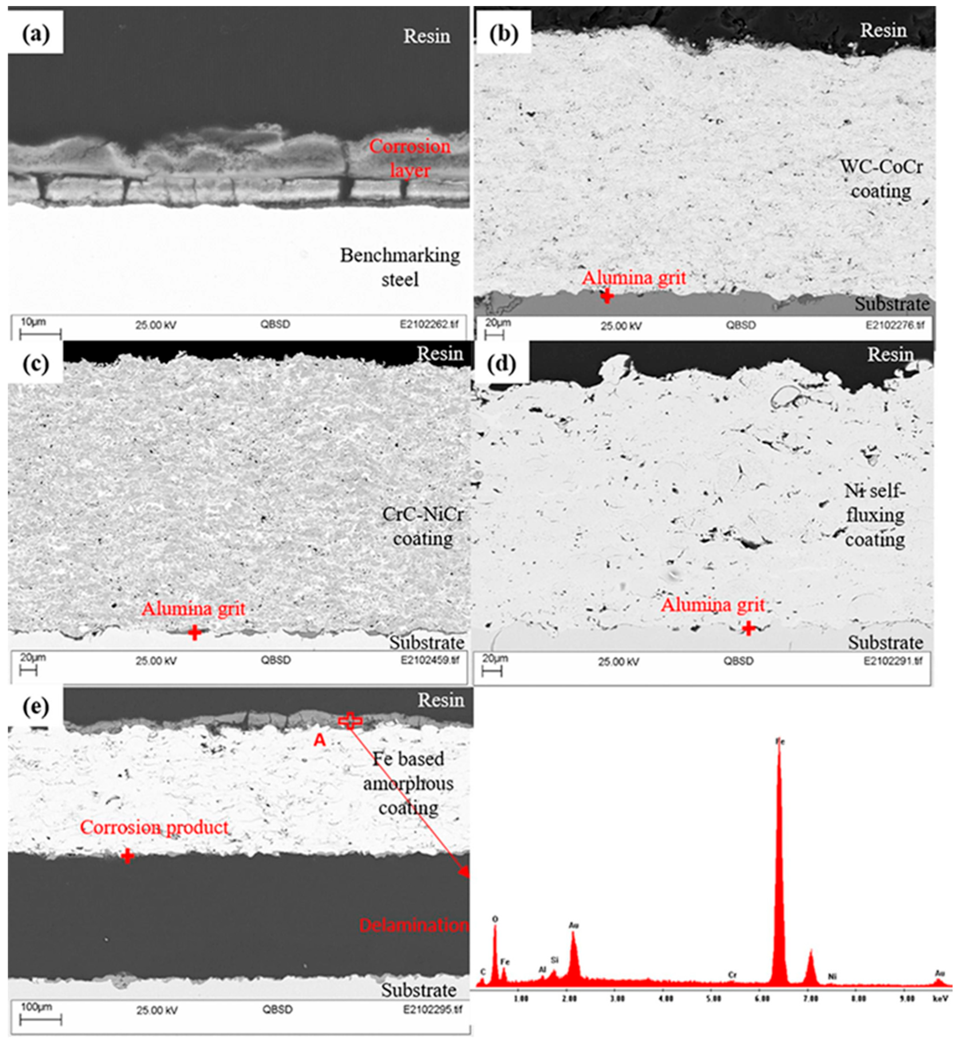
Cermet (WC-CoCr and CrC-NiCr), Ni-self fluxing and Fe-based amorphous coatingsLow-alloy steel (34CrNiMo6)HVOF-Roughness, Ra: 4.3 ± 0.5 µm (WC-CoCr), 3.5 ± 0.7 µm (CrC-NiCr), 6.4 ± 0.4 µm (Ni-flux coatings), 8.5 ± 0.4 µm (Fe-based amorphous coatings); thickness: 341 ± 9.9 µm (WC-CoCr), 316.6 ± 7.9 µm (CrC-NiCr), 285.6 ± 13.9 µm (Ni-flux coatings), 281.4 ± 12.9 µm (Fe-based amorphous coatings)[43]
PTFE-blended PPSC-steelFill-drainbakingSilica scaling-[99]
ZnPh (primer) + SiC-PPS and ZnPh + ACA filled PPSStainless steelFill-drain-bakingAnti-fouling and anti-corrosionThickness: 300–330 µm (liners) and 8–60 µm (Zn-Ph primer)[100]

4. Challenges and Future Direction

In geothermal power plants, paints and coatings could be a feasible and economical solution to mitigate various issues, including corrosion, scaling, erosion, and fouling. This is advantageous compared to the expensive replacement of power plant components. However, no universal coating method or material is suitable for all geothermal heat exchangers, as the selection and design of a coating system depend on the geothermal fluid chemistry influenced by geographical location and heat exchanger configuration. Despite promising advantages, coatings for geothermal heat exchangers face challenges associated with extreme conditions, corrosive environments, cost, and scalability. Designed coatings must withstand extreme thermal gradients, aggressive fluids, and mechanical stress by maintaining their integrity and functionality. Key factors influencing coating performance and durability include coating adhesion, (uniform) coating thickness, porosity, and surface energy. These factors vary with the coating deposition method, emphasizing the value of carefully considering coating methods in accordance with the specific application requirements.
In addition, the developed coating must be compatible with the substrate to ensure good adhesion, efficient heat transfer, and minimized (galvanic) corrosion between the coating and substrate. Coatings must also be compatible with a broad spectrum of geothermal fluids, preventing adverse reactions between the coating and geothermal fluid. Scalability is another challenge that needs to be addressed, as some coating methods are size- and/or shape-restricted. For instance, thermal spray is a line-of-sight process unsuitable for coating complex geometries in geothermal infrastructure. Similarly, heavy components of the heat exchangers cannot be coated using CVD as there is a specific weight limit that a quartz tube can sustain during deposition. Since coating development can be expensive, balancing performance benefits and the associated costs is also challenging. Nowadays, considering the environmental sustainability of coating materials, developmental methods, and the end of the coating lifecycle is crucial in diminishing the detrimental environmental impacts.
Addressing these challenges with the help of ongoing research and innovation, the development of durable, efficient, and sustainable coating solutions for geothermal applications is possible. There is not much research in the literature related to coating development for geothermal heat exchangers. Still, the knowledge can be acquired from other sectors where coating systems are used in harsh environments, such as hydrothermal power and biomass power production, which could provide a potential solution for the protection and performance enhancement of geothermal heat exchangers. Implementing multifunctional coatings with novel ceramics, nanomaterials, and composites can mitigate corrosion, scaling, and fouling issues and improve heat transfer efficiency. Innovative coatings with self-healing properties and integrated sensors could be a promising solution for early detection problems, monitoring real-time conditions, and autonomous repairing. This would also help in reducing the O&M costs. Apart from these advancements, the industry-specific standardisation and regulations for geothermal coatings would also help their widespread implementation.
In short, the prospect for coatings in geothermal heat exchangers is very promising, which, with the collective efforts of researchers, industry stakeholders, and policymakers, would help geothermal power plants that integrate unconventional coatings to become sustainable and reliable sources of clean and renewable energy.

Author Contributions

Conceptualization S.P.; methodology S.P., A.B.N.J., N.G.M. and G.M.; investigation, A.B.N.J. and N.G.M.; data curation A.B.N.J. and N.G.M.; writing—A.B.N.J., N.G.M. and G.M.; writing—review and editing, A.B.N.J., N.G.M., G.M. and D.M.; supervision S.P.; project administration D.M., S.P. and N.K. All authors have read and agreed to the published version of the manuscript.

Funding

This project has received funding from the European Union’s Horizon 2020 research and innovation programme under the following project: GeoHex-advanced material for cost-efficient and enhanced heat exchange performance for geothermal application (Grant agreement 851917).

Data Availability Statement

Data are contained within the article.

Acknowledgments

We want to acknowledge the contribution of the GeoHex consortium to this project.

Conflicts of Interest

The authors declare no conflict of interest.

References

  1. Agency, I.E. CO2 Emissions in 2022. Available online: https://iea.blob.core.windows.net/assets/3c8fa115-35c4-4474-b237-1b00424c8844/CO2Emissionsin2022.pdf (accessed on 1 September 2023).
  2. IRENA; IGA. Global Geothermal Market and Technology Assessment; Internation Renewable Energy Agency: Abu Dhabi, United Arab Emirates; International Geothermal Association: The Hague, The Netherlands, 2023. [Google Scholar]
  3. Kumar, L.; Hossain, M.S.; Assad, M.E.H.; Manoo, M.U. Technological Advancements and Challenges of Geothermal Energy Systems: A Comprehensive Review. Energies 2022, 15, 9058. [Google Scholar] [CrossRef]
  4. Gunnlaugsson, E.; Ármannsson, H.; Thorhallsson, S.; Steingrímsson, B. Problems in Geothermal Operation–Scaling and Corrosion; Goethermal Training Program, United Nations University: Santa Tecla, El Salvador, 2014; pp. 1–18. [Google Scholar]
  5. Stefansson, V. Investment cost for geothermal power plants. Geothermics 2002, 31, 263–272. [Google Scholar] [CrossRef]
  6. Corinna Abesser, D.A.W. Geothermal Energy; UK Parliament Post: London, UK, 2022. [Google Scholar]
  7. Gurgenci, H.; Rudolph, V.; Saha, T.; Lu, M. Challenges for geothermal energy utilisation. In Proceedings of the Thirty-Third Workshop on Geothermal Reservoir Engineering, Stanford, CA, USA, 28–30 January 2008. SGP-TR-185. [Google Scholar]
  8. Spadacini, C.; Xodo, L.; Quaia, M. Geothermal energy exploitation with Organic Rankine Cycle technologies. In Organic Rankine Cycle (ORC) Power Systems; Elsevier: Amsterdam, The Netherlands, 2017; pp. 473–525. [Google Scholar]
  9. Valdimarsson, P. Geothermal power plant cycles and main components. In Short Course on Geothermal Drilling, Resource Development and Power Plants; Goethermal Training Program, United Nations University: Santa Tecla, El Salvador, 2011; p. 24. [Google Scholar]
  10. Frick, S.; Regenspurg, S.; Kranz, S.; Milsch, H.; Saadat, A.; Francke, H.; Brandt, W.; Huenges, E. Geochemical and process engineering challenges for geothermal power generation. Chem. Ing. Tech. 2011, 83, 2093–2104. [Google Scholar] [CrossRef]
  11. Haklıdır, F.S.T.; Balaban, T.Ö. A review of mineral precipitation and effective scale inhibition methods at geothermal power plants in West Anatolia (Turkey). Geothermics 2019, 80, 103–118. [Google Scholar] [CrossRef]
  12. Manzella, A. Geothermal energy. EPJ Web Conf. 2017, 148, 00012. [Google Scholar] [CrossRef]
  13. Fanicchia, F.; Karlsdottir, S.N. Research and Development on Coatings and Paints for Geothermal Environments: A Review. Adv. Mater. Technol. 2023, 8, 2202031. [Google Scholar] [CrossRef]
  14. Ghalandari, M.; Irandoost Shahrestani, M.; Maleki, A.; Safdari Shadloo, M.; El Haj Assad, M. Applications of intelligent methods in various types of heat exchangers: A review. J. Therm. Anal. Calorim. 2021, 145, 1837–1848. [Google Scholar] [CrossRef]
  15. Ma, Y.; Xie, G.; Hooman, K. Review of printed circuit heat exchangers and its applications in solar thermal energy. Renew. Sustain. Energy Rev. 2022, 155, 111933. [Google Scholar] [CrossRef]
  16. Wang, B.; Klemeš, J.J.; Li, N.; Zeng, M.; Varbanov, P.S.; Liang, Y. Heat exchanger network retrofit with heat exchanger and material type selection: A review and a novel method. Renew. Sustain. Energy Rev. 2021, 138, 110479. [Google Scholar] [CrossRef]
  17. Kapustenko, P.; Klemeš, J.; Arsenyeva, O.; Matsegora, O.; Vasilenko, O. Accounting for local features of fouling formation on PHE heat transfer surface. Front. Chem. Sci. Eng. 2018, 12, 619–629. [Google Scholar] [CrossRef]
  18. Shah, R.K.; Sekulic, D.P. Fundamentals of Heat Exchanger Design; John Wiley & Sons: Hoboken, NJ, USA, 2003. [Google Scholar]
  19. Zarrouk, S.J.; Woodhurst, B.C.; Morris, C. Silica scaling in geothermal heat exchangers and its impact on pressure drop and performance: Wairakei binary plant, New Zealand. Geothermics 2014, 51, 445–459. [Google Scholar] [CrossRef]
  20. Kazi, S.; Teng, K.; Zakaria, M.; Sadeghinezhad, E.; Bakar, M. Study of mineral fouling mitigation on heat exchanger surface. Desalination 2015, 367, 248–254. [Google Scholar] [CrossRef]
  21. He, Z.; Liu, C.; Gao, H.; Jie, X.; Lian, W. Experimental study on the anti-fouling effects of EDM machined hierarchical micro/nano structure for heat transfer surface. Appl. Therm. Eng. 2019, 162, 114248. [Google Scholar] [CrossRef]
  22. Malayeri, M.; Al-Janabi, A.; Müller-Steinhagen, H. Application of nano-modified surfaces for fouling mitigation. Int. J. Energy Res. 2009, 33, 1101–1113. [Google Scholar] [CrossRef]
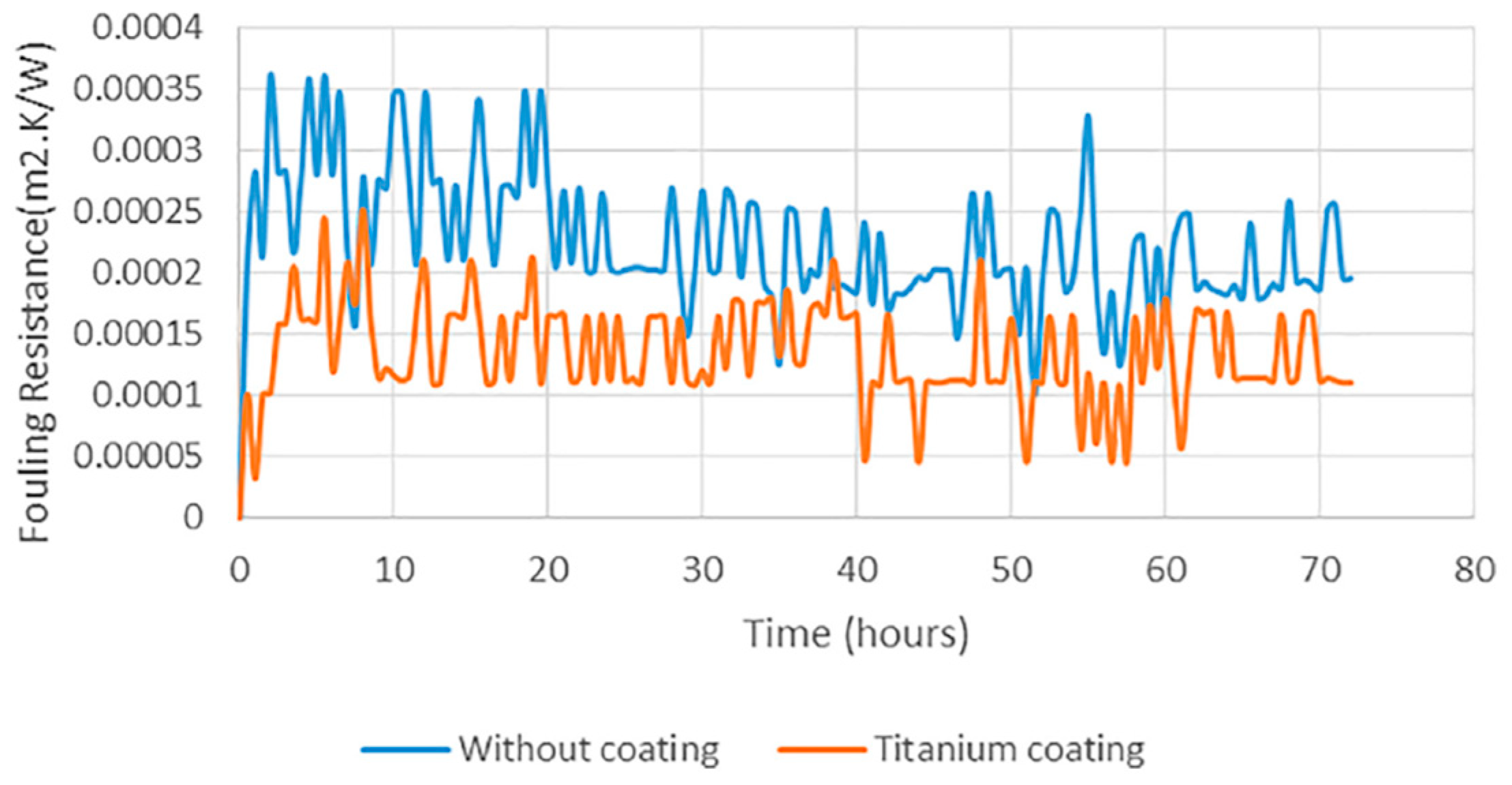
  23. Oon, C.S.; Kazi, S.N.; Hakimin, M.A.; Abdelrazek, A.H.; Mallah, A.R.; Low, F.W.; Tiong, S.K.; Badruddin, I.A.; Kamanger, S. Heat transfer and fouling deposition investigation on the titanium coated heat exchanger surface. Powder Technol. 2020, 373, 671–680. [Google Scholar] [CrossRef]
  24. Ledésert, B.A.; Hébert, R.L.; Mouchot, J.; Bosia, C.; Ravier, G.; Seibel, O.; Dalmais, É.; Ledésert, M.; Trullenque, G.; Sengelen, X. Scaling in a geothermal heat exchanger at soultz-sous-forêts (Upper Rhine Graben, France): A XRD and SEM-EDS characterization of sulfide precipitates. Geosciences 2021, 11, 271. [Google Scholar] [CrossRef]
  25. Iberl, P.; Alt, N.; Schluecker, E. Evaluation of corrosion of materials for application in geothermal systems in Central Europe. Mater. Corros. 2015, 66, 733–755. [Google Scholar] [CrossRef]
  26. Dwivedi, S.K.; Vishwakarma, M. Hydrogen embrittlement in different materials: A review. Int. J. Hydrogen Energy 2018, 43, 21603–21616. [Google Scholar] [CrossRef]
  27. Morake, J.B.; Mutua, J.M.; Ruthandi, M.M.; Olakanmi, E.O.; Botes, A. Failure analysis of corroded heat exchanger CuNi tubes from a geothermal plant. Eng. Fail. Anal. 2023, 153, 107543. [Google Scholar] [CrossRef]
  28. Mundhenk, N.; Huttenloch, P.; Sanjuan, B.; Kohl, T.; Steger, H.; Zorn, R. Corrosion and scaling as interrelated phenomena in an operating geothermal power plant. Corros. Sci. 2013, 70, 17–28. [Google Scholar] [CrossRef]
  29. Faes, W.; Lecompte, S.; Ahmed, Z.Y.; Van Bael, J.; Salenbien, R.; Verbeken, K.; De Paepe, M. Corrosion and corrosion prevention in heat exchangers. Corros. Rev. 2019, 37, 131–155. [Google Scholar] [CrossRef]
  30. Davíðsdóttir, S.; Gunnarsson, B.G.; Kristjánsson, K.B.; Ledésert, B.A.; Ólafsson, D.I. Study of Corrosion Resistance Properties of Heat Exchanger Metals in Two Different Geothermal Environments. Geosciences 2021, 11, 498. [Google Scholar] [CrossRef]
  31. Müller-Steinhagen, H.; Malayeri, M.; Watkinson, A. Heat Exchanger Fouling: Mitigation and Cleaning Strategies; Taylor & Francis: Abingdon, UK, 2011; Volume 32, pp. 189–196. [Google Scholar]
  32. Gill, J.S. New Inhibitors for silica and calcium carbonate control in geothermal. In Proceedings of the International Workshop on Mineral Scaling, Manila, Philippines, 25–27 May 2011. [Google Scholar]
  33. Gallup, D.L.; Barcelon, E. Investigations of organic inhibitors for silica scale control from geothermal brines–II. Geothermics 2005, 34, 756–771. [Google Scholar] [CrossRef]
  34. Gallup, D.L. Investigations of organic inhibitors for silica scale control in geothermal brines. Geothermics 2002, 31, 415–430. [Google Scholar] [CrossRef]
  35. Scheiber, J.; Seibt, A.; Birner, J.; Genter, A.; Moeckes, W. Application of a scaling inhibitor system at the geothermal power plant in Soultz-sous-Forêts: Laboratory and on-site studies. In Proceedings of the European Geothermal Congress, Pisa, Italy, 3–7 June 2013; pp. 3–7. [Google Scholar]
  36. Stapleton, M.; Weres, O. Recent developments in geothermal scale control. In Proceedings of the International Workshop on Mineral Scaling, Manila, Philippines, 25–27 May 2011. [Google Scholar]
  37. Cho, Y.; Choi, B.-G. Validation of an electronic anti-fouling technology in a single-tube heat exchanger. Int. J. Heat Mass Transf. 1999, 42, 1491–1499. [Google Scholar] [CrossRef]
  38. He, Z.; Liu, C.; Jie, X.; Lian, W.; Luo, S. Preparation of anti-fouling heat transfer surface by magnetron sputtering aC film on electrical discharge machining Cu surface. Surf. Coat. Technol. 2019, 369, 44–51. [Google Scholar] [CrossRef]
  39. Wang, G.G.; Zhu, L.Q.; Liu, H.C.; Li, W.P. Self-assembled biomimetic superhydrophobic CaCO3 coating inspired from fouling mineralization in geothermal water. Langmuir 2011, 27, 12275–12279. [Google Scholar] [CrossRef]
  40. He, Z.; Luo, S.; Liu, C.; Jie, X.; Lian, W. Hierarchical micro/nano structure surface fabricated by electrical discharge machining for anti-fouling application. J. Mater. Res. Technol. 2019, 8, 3878–3890. [Google Scholar] [CrossRef]
  41. Cadelano, G.; Bortolin, A.; Ferrarini, G.; Bison, P.; Dalla Santa, G.; Di Sipio, E.; Bernardi, A.; Galgaro, A. Evaluation of the effect of anti-corrosion coatings on the thermal resistance of ground heat exchangers for shallow geothermal applications. Energies 2021, 14, 2586. [Google Scholar] [CrossRef]
  42. Joshi, S.V.; Sivakumar, G. Hybrid Processing with Powders and Solutions: A Novel Approach to Deposit Composite Coatings. J. Therm. Spray Technol. 2015, 24, 1166–1186. [Google Scholar] [CrossRef]
  43. Zhang, F.; Tabecki, A.; Bennett, M.; Begg, H.; Lionetti, S.; Paul, S. Feasibility Study of High-Velocity Oxy-fuel (HVOF) Sprayed Cermet and Alloy Coatings for Geothermal Applications. J. Therm. Spray Technol. 2023, 32, 339–351. [Google Scholar] [CrossRef]
  44. Oppong Boakye, G.; Geambazu, L.E.; Ormsdottir, A.M.; Gunnarsson, B.G.; Csaki, I.; Fanicchia, F.; Kovalov, D.; Karlsdottir, S.N. Microstructural Properties and Wear Resistance of Fe-Cr-Co-Ni-Mo-Based High Entropy Alloy Coatings Deposited with Different Coating Techniques. Appl. Sci. 2022, 12, 3156. [Google Scholar] [CrossRef]
  45. Azarmi, F.; Chen, X.; Cizek, J.; Cojocaru, C.; Jodoin, B.; Koivuluoto, H.; Lau, Y.C.; Fernandez, R.; Ozdemir, O.; Salimi Jazi, H.; et al. Development of Suspension-Based Plasma and HVOF Spray TiO2 Coatings. In Proceedings of the International Thermal Spray Conference, Virtual, 24–28 May 2021; pp. 489–492. [Google Scholar]
  46. Bolelli, G.; Candeli, A.; Lusvarghi, L.; Ravaux, A.; Cazes, K.; Denoirjean, A.; Valette, S.; Chazelas, C.; Meillot, E.; Bianchi, L. Tribology of NiCrAlY+Al2O3 composite coatings by plasma spraying with hybrid feeding of dry powder+suspension. Wear 2015, 344–345, 69–85. [Google Scholar] [CrossRef]
  47. Murray, J.W.; Leva, A.; Joshi, S.; Hussain, T. Microstructure and wear behaviour of powder and suspension hybrid Al2O3–YSZ coatings. Ceram. Int. 2018, 44, 8498–8504. [Google Scholar] [CrossRef]
  48. Gopal, V.; Goel, S.; Manivasagam, G.; Joshi, S. Performance of Hybrid Powder-Suspension Axial Plasma Sprayed Al2O3-YSZ Coatings in Bovine Serum Solution. Materials 2019, 12, 1922. [Google Scholar] [CrossRef]
  49. Kiilakoski, J.; Puranen, J.; Heinonen, E.; Koivuluoto, H.; Vuoristo, P. Characterization of Powder-Precursor HVOF-Sprayed Al2O3-YSZ/ZrO2 Coatings. J. Therm. Spray Technol. 2018, 28, 98–107. [Google Scholar] [CrossRef]
  50. Buzaianu, A.; Motoiu, P.; Csaki, I.; Ioncea, A.; Motoiu, V. Structural Properties Ni20Cr10Al2Y Coatings for Geothermal Conditions. In Proceedings of the 2nd International Research Conference on Sustainable Energy, Engineering, Materials and Environment, Mieres, Spain, 25–27 September 2018. [Google Scholar]
  51. Kern, W.; Schuegraf, K.K. Deposition technologies and applications: Introduction and overview. In Handbook of Thin Film Deposition Processes and Techniques; Elsevier: Amsterdam, The Netherlands, 2001; pp. 11–43. [Google Scholar]
  52. Manawi, Y.M.; Ihsanullah; Samara, A.; Al-Ansari, T.; Atieh, M.A. A Review of Carbon Nanomaterials’ Synthesis via the Chemical Vapor Deposition (CVD) Method. Materials 2018, 11, 822. [Google Scholar] [CrossRef] [PubMed]
  53. Kafizas, A.; Carmalt, C.J.; Parkin, I.P. CVD and precursor chemistry of transition metal nitrides. Coord. Chem. Rev. 2013, 257, 2073–2119. [Google Scholar] [CrossRef]
  54. Preston, D.J.; Mafra, D.L.; Miljkovic, N.; Kong, J.; Wang, E.N. Scalable graphene coatings for enhanced condensation heat transfer. Nano Lett. 2015, 15, 2902–2909. [Google Scholar] [CrossRef]
  55. Mishra, R.; Ningthoujam, R.S. High-Temperature Ceramics. In Materials Under Extreme Conditions; Elsevier: Amsterdam, The Netherlands, 2017; pp. 377–409. [Google Scholar] [CrossRef]
  56. Li, Z.; Aik Khor, K. Preparation and Properties of Coatings and Thin Films on Metal Implants. In Encyclopedia of Biomedical Engineering; Elsevier: Amsterdam, The Netherlands, 2019; pp. 203–212. [Google Scholar] [CrossRef]
  57. Ali, N.; Teixeira, J.A.; Addali, A.; Saeed, M.; Al-Zubi, F.; Sedaghat, A.; Bahzad, H. Deposition of Stainless Steel Thin Films: An Electron Beam Physical Vapour Deposition Approach. Materials 2019, 12, 571. [Google Scholar] [CrossRef]
  58. Arunkumar, P.; Aarthi, U.; Sribalaji, M.; Mukherjee, B.; Keshri, A.K.; Tanveer, W.H.; Cha, S.-W.; Babu, K.S. Deposition rate dependent phase/mechanical property evolution in zirconia and ceria-zirconia thin film by EB-PVD technique. J. Alloys Compd. 2018, 765, 418–427. [Google Scholar] [CrossRef]
  59. Makhlouf, A. Current and advanced coating technologies for industrial applications. In Nanocoatings and Ultra-Thin Films; Elsevier: Amsterdam, The Netherlands, 2011; pp. 3–23. [Google Scholar]
  60. Ali, N.; Teixeira, J.A.; Addali, A. Effect of Water Temperature, pH Value, and Film Thickness on the Wettability Behaviour of Copper Surfaces Coated with Copper Using EB-PVD Technique. J. Nano Res. 2019, 60, 124–141. [Google Scholar] [CrossRef]
  61. Park, H.; Kim, K.Y.; Choi, W. Photoelectrochemical approach for metal corrosion prevention using a semiconductor photoanode. J. Phys. Chem. B 2002, 106, 4775–4781. [Google Scholar] [CrossRef]
  62. Liu, Y.; Xu, C.; Feng, Z. Characteristics and anticorrosion performance of Fe-doped TiO2 films by liquid phase deposition method. Appl. Surf. Sci. 2014, 314, 392–399. [Google Scholar] [CrossRef]
  63. Deki, S.; Aoi, Y.; Hiroi, O.; Kajinami, A. Titanium (IV) oxide thin films prepared from aqueous solution. Chem. Lett. 1996, 25, 433–434. [Google Scholar] [CrossRef]
  64. Fujita, R.; Sakairi, M.; Kikuchi, T.; Nagata, S. Corrosion resistant TiO2 film formed on magnesium by liquid phase deposition treatment. Electrochim. Acta 2011, 56, 7180–7188. [Google Scholar] [CrossRef]
  65. Lee, M.-K.; Fan, C.-H.; Wang, H.-C.; Chang, C.-Y. Fluorine passivation of titanium oxide films on ITO/glass grown by liquid phase deposition for electrochroism. J. Electrochem. Soc. 2011, 158, D511. [Google Scholar] [CrossRef]
  66. Arnelli, A.; Rahayu, R.A.Y.S.; Astuti, Y. Synthesis, Characterization, and Antibacterial Activity Test of Geothermal Silica/AgNO3 Thin Film. Molekul 2023, 18, 186. [Google Scholar]
  67. Gutiérrez-Tauste, D.; Domènech, X.; Hernández-Fenollosa, M.A.; Ayllón, J.A. Alternative fluoride scavengers to produce TiO2 films by the liquid phase deposition (LPD) technique. J. Mater. Chem. 2006, 16, 2249–2255. [Google Scholar] [CrossRef]
  68. Yu, J.; Yu, H.; Ao, C.; Lee, S.; Jimmy, C.Y.; Ho, W. Preparation, characterization and photocatalytic activity of in situ Fe-doped TiO2 thin films. Thin Solid Film. 2006, 496, 273–280. [Google Scholar] [CrossRef]
  69. Tu, Y.-F.; Huang, S.-Y.; Sang, J.-P.; Zou, X.-W. Preparation of Fe-doped TiO2 nanotube arrays and their photocatalytic activities under visible light. Mater. Res. Bull. 2010, 45, 224–229. [Google Scholar] [CrossRef]
  70. Song, J.; Liu, M.; Sun, X.; Wang, J.; Zhu, J. Antifouling and anticorrosion behaviors of modified heat transfer surfaces with coatings in simulated hot-dry-rock geothermal water. Appl. Therm. Eng. 2018, 132, 740–759. [Google Scholar] [CrossRef]
  71. Valiulis, A.V.; Silickas, P. Liquid phase deposition methods monitoring techniques influence for solid substrates and thin metal oxide films properties. J. Achiev. Mater. Manuf. Eng. 2007, 24, 188–192. [Google Scholar]
  72. Zhang, F.; Liu, M.; Zhou, W. Inhibition of Fouling with Titania and Silica Coatings on Plate Heat Exchanger in 80 °C Simulated Geothermal Water. Heat Exch. Fouling Clean. 2017, 8, 183–190. [Google Scholar]
  73. Aristia, G.; Bäßler, R.; Nofz, M.; Sojref, R.; Kohl, A. Short-term exposure tests of ɣ-Al2O3 Sol-gel coating on X20Cr13 in artificial geothermal waters with different pH. Geothermics 2021, 96, 102193. [Google Scholar] [CrossRef]
  74. Li, W.; Seal, S.; Megan, E.; Ramsdell, J.; Scammon, K.; Lelong, G.; Lachal, L.; Richardson, K.A. Physical and optical properties of sol-gel nano-silver doped silica film on glass substrate as a function of heat-treatment temperature. J. Appl. Phys. 2003, 93, 9553–9561. [Google Scholar] [CrossRef]
  75. Schulz, W.; Nofz, M.; Feigl, M.; Dörfel, I.; Saliwan Neumann, R.; Kranzmann, A. Corrosion of uncoated and alumina coated steel X20CrMoV12-1 in H2O–CO2–O2 and air at 600 °C. Corros. Sci. 2013, 68, 44–50. [Google Scholar] [CrossRef]
  76. Nofz, M.; Zietelmann, C.; Feigl, M.; Dörfel, I.; Saliwan Neumann, R. Microstructural origin of time-dependent changes in alumina sol–gel-coated Inconel 718 exposed to NaCl solution. J. Sol-Gel Sci. Technol. 2015, 75, 6–16. [Google Scholar] [CrossRef]
  77. Muench, F. Electroless plating of metal nanomaterials. ChemElectroChem 2021, 8, 2993–3012. [Google Scholar] [CrossRef]
  78. Loto, C. Electroless nickel plating—A review. Silicon 2016, 8, 177–186. [Google Scholar] [CrossRef]
  79. Zhang, H.; Zou, J.; Lin, N.; Tang, B. Review on electroless plating Ni–P coatings for improving surface performance of steel. Surf. Rev. Lett. 2014, 21, 1430002. [Google Scholar] [CrossRef]
  80. Ren, L.; Cheng, Y.; Yang, J.; Wang, Q. Study on heat transfer performance and anti-fouling mechanism of ternary Ni-WP coating. Appl. Sci. 2020, 10, 3905. [Google Scholar] [CrossRef]
  81. Sharma, A.; Cheon, C.-S.; Jung, J.P. Recent progress in electroless plating of copper. J. Microelectron. Packag. Soc. 2016, 23, 1–6. [Google Scholar] [CrossRef]
  82. Boakye, G.O.; Ormsdóttir, A.M.; Gunnarsson, B.G.; Irukuvarghula, S.; Khan, R.; Karlsdóttir, S.N. The effect of polytetrafluoroethylene (PTFE) particles on microstructural and tribological properties of electroless Ni-P+PTFE duplex coatings developed for geothermal applications. Coatings 2021, 11, 670. [Google Scholar] [CrossRef]
  83. Cheng, Y.; Zou, Y.; Cheng, L.; Liu, W. Effect of the microstructure on the anti-fouling property of the electroless Ni–P coating. Mater. Lett. 2008, 62, 4283–4285. [Google Scholar] [CrossRef]
  84. Cheng, Y.; Chen, H.; Zhu, Z.; Jen, T.; Peng, Y. Experimental study on the anti-fouling effects of Ni–Cu–P-PTFE deposit surface of heat exchangers. Appl. Therm. Eng. 2014, 68, 20–25. [Google Scholar] [CrossRef]
  85. Cheng, Y.; Chen, S.; Jen, T.; Zhu, Z.; Peng, Y. Effect of copper addition on the properties of electroless Ni-Cu-P coating on heat transfer surface. Int. J. Adv. Manuf. Technol. 2015, 76, 2209–2215. [Google Scholar] [CrossRef]
  86. Krishnan, K.H.; John, S.; Srinivasan, K.; Praveen, J.; Ganesan, M.; Kavimani, P. An overall aspect of electroless Ni-P depositions—A review article. Metall. Mater. Trans. A 2006, 37, 1917–1926. [Google Scholar] [CrossRef]
  87. Rozmus-Górnikowska, M.; Blicharski, M.; Kusiński, J. Influence of weld overlaying methods on microstructure and chemical composition of Inconel 625 boiler pipe coatings. Kov. Mater. 2014, 52, 1–7. [Google Scholar] [CrossRef]
  88. Rao, N.V.; Reddy, G.M.; Nagarjuna, S. Weld overlay cladding of high strength low alloy steel with austenitic stainless steel–structure and properties. Mater. Des. 2011, 32, 2496–2506. [Google Scholar]
  89. Volpi, A.; Serra, G. Weld overlay of highly corrosion resistant nickel chromium molybdenum alloys, UNS N06059, on low alloy equipment operating at high temperature. In Proceedings of the ASME 2018 Symposium on Elevated Temperature Application of Materials for Fossil, Nuclear, and Petrochemical Industries, Seattle, WA, USA, 3–5 April 2018; p. V001T002A003. [Google Scholar]
  90. Saito, S. Technologies for High Performance and Reliability of Geothermal Power Plant. In Proceedings of the World Geothermal Congress, Bali, Indonesia, 25–29 April 2010; pp. 1–4. [Google Scholar]
  91. Tayactac, R.G.; Ang, E.B. A Review of Corrosion Resistance Alloy Weld Overlay Cladding Material for Geothermal Applications. Mater. Sci. Forum 2021, 1047, 120–127. [Google Scholar] [CrossRef]
  92. Yoon, S.Y.; Choi, S.-E.; Lee, J.S. Liquid Phase Deposition of Silica on the Hexagonally Close-Packed Monolayer of Silica Spheres. J. Nanomater. 2013, 2013, 510524. [Google Scholar] [CrossRef]
  93. Kishimoto, H.; Takahama, K.; Hashimoto, N.; Aoi, Y.; Deki, S. Photocatalytic activity of titanium oxide prepared by liquid phase deposition (LPD). J. Mater. Chem. 1998, 8, 2019–2024. [Google Scholar] [CrossRef]
  94. Lu, P.; Ding, B. Nano-modification of textile surfaces using layer-by-layer deposition methods. In Surface Modification of Textiles; Elsevier: Amsterdam, The Netherlands, 2009; pp. 214–237. [Google Scholar] [CrossRef]
  95. Danks, A.E.; Hall, S.R.; Schnepp, Z. The evolution of ‘sol–gel’ chemistry as a technique for materials synthesis. Mater. Horiz. 2016, 3, 91–112. [Google Scholar] [CrossRef]
  96. Bokov, D.; Turki Jalil, A.; Chupradit, S.; Suksatan, W.; Javed Ansari, M.; Shewael, I.H.; Valiev, G.H.; Kianfar, E.; Wang, Z. Nanomaterial by Sol-Gel Method: Synthesis and Application. Adv. Mater. Sci. Eng. 2021, 2021, 5102014. [Google Scholar] [CrossRef]
  97. Modan, E.M.; PlĂIaȘU, A.G. Advantages and Disadvantages of Chemical Methods in the Elaboration of Nanomaterials. Ann. Dunarea Jos Univ. Galati. Fascicle IX Metall. Mater. Sci. 2020, 43, 53–60. [Google Scholar] [CrossRef]
  98. Losada, R.; Holberg, S.; Freire, L.; Van Bael, J. High performance antifouling/anticorrosion coatings for protecting carbon steel and low alloying stainless steel heat exchangers in low enthalpy geothermal fluids. In Proceedings of the Heat Exchanger Fouling and Cleaning XIII, Warsaw, Poland, 2–7 June 2019; pp. 2–7. [Google Scholar]
  99. Sugama, T.; Gawlik, K. Anti-silica fouling coatings in geothermal environments. Mater. Lett. 2002, 57, 666–673. [Google Scholar] [CrossRef]
  100. Sugama, T.; Elling, D.; Gawlik, K. Poly (phenylenesulfide)-based coatings for carbon steel heat exchanger tubes in geothermal environments. J. Mater. Sci. 2002, 37, 4871–4880. [Google Scholar] [CrossRef]
  101. Sugama, T.; Sabatini, R.; Gawlik, K. Self-Assembly Ce Oxide/Organopolysiloxane Composite Coatings; Brookhaven National Lab.(BNL): Upton, NY, USA, 2005. [Google Scholar]
  102. Gawlik, K.; Sugama, T.; Jung, D. Organometallic Polymer Coatings for Geothermal-Fluid-Sprayed Air-Cooled Condensers; National Renewable Energy Lab.: Golden, CO, USA, 2002. [Google Scholar]
  103. Soltani, M.; Kashkooli, F.M.; Fini, M.A.; Gharapetian, D.; Nathwani, J.; Dusseault, M.B. A review of nanotechnology fluid applications in geothermal energy systems. Renew. Sustain. Energy Rev. 2022, 167, 112729. [Google Scholar] [CrossRef]
  104. Diglio, G.; Roselli, C.; Sasso, M.; Channabasappa, U.J. Borehole heat exchanger with nanofluids as heat carrier. Geothermics 2018, 72, 112–123. [Google Scholar] [CrossRef]
  105. Hussein, A.K. Applications of nanotechnology in renewable energies—A comprehensive overview and understanding. Renew. Sustain. Energy Rev. 2015, 42, 460–476. [Google Scholar] [CrossRef]
  106. Goswami, A.; Pillai, S.C.; McGranaghan, G. Micro/Nanoscale Surface Modifications to Combat Heat Exchanger Fouling. Chem. Eng. J. Adv. 2023, 16, 100519. [Google Scholar] [CrossRef]
  107. Kabeel, A.; Abou El Maaty, T.; El Samadony, Y. The effect of using nano-particles on corrugated plate heat exchanger performance. Appl. Therm. Eng. 2013, 52, 221–229. [Google Scholar] [CrossRef]
  108. Cheng, K.; Yang, E.; Lee, C.Y.; Ricks, Z.; Palmre, V.; Kim, K. Fine-tuned polymer Nano-composite coatings for use in geothermal plants. In Proceedings of the Smart Materials, Adaptive Structures and Intelligent Systems, Scottsdale, AZ, USA, 18–21 September 2011; pp. 713–719. [Google Scholar]
  109. Sugama, T. Polyphenylenesulphide-sealed Ni–Al coatings for protecting steel from corrosion and oxidation in geothermal environments. J. Mater. Sci. 1998, 33, 3791–3803. [Google Scholar] [CrossRef]
  110. Sugama, T. Interfaces between geothermal brine-induced scales and SiC-filled polymer linings. Geothermics 1998, 27, 387–400. [Google Scholar] [CrossRef]
  111. Sugama, T. Antioxidants for retarding hydrothermal oxidation of polyphenylenesulfide coatings in geothermal environments. Mater. Lett. 2000, 43, 185–191. [Google Scholar] [CrossRef]
  112. Sugama, T.; Gawlik, K. Carbon fibre-reinforced poly (phenylenesulphide) composite coatings. Polym. Polym. Compos. 2001, 9, 377–384. [Google Scholar] [CrossRef]
  113. Sugama, T. Polyphenylenesulfied/montomorillonite clay nanocomposite coatings: Their efficacy in protecting steel against corrosion. Mater. Lett. 2006, 60, 2700–2706. [Google Scholar] [CrossRef]
  114. Cai, Y.; Quan, X.; Li, G.; Gao, N. Anticorrosion and scale behaviors of nanostructured ZrO2–TiO2 coatings in simulated geothermal water. Ind. Eng. Chem. Res. 2016, 55, 11480–11494. [Google Scholar] [CrossRef]
  115. Wang, G.; Zhu, L.; Liu, H.; Li, W. Zinc-graphite composite coating for anti-fouling application. Mater. Lett. 2011, 65, 3095–3097. [Google Scholar] [CrossRef]
Figure 1. (a) Kızıldere-I single flash-type geothermal powerplant in the BMG, reprinted with permission from Elsevier [11] and (b) schematic demonstrating working of ORC binary geothermal powerplant inspired from [12].
Coatings 13 01988 g001
Figure 3. Corrosion rate of mild steel from autoclave measurements at different temperatures, reprinted with permission from Elsevier [28].
Coatings 13 01988 g003
Figure 4. Corrosion of different heat exchanger materials exposed to pressure vessel at Reykjanes and flow line pipe at Chaunoy, where red circles mark the area masked partially from geothermal environment and the blue box indicates the exposed area of Ti gr.2; reproduced from [30] under Creative Commons CC BY license, Copyright © 2023, The Author(s).
Coatings 13 01988 g004
Figure 5. Different forms of corrosion and scaling in geothermal environment.
Coatings 13 01988 g005
Figure 6. Image demonstrating formation of calcium carbonate deposits on an uncoated stainless steel (SS 316L) and titanium-coated stainless steel surface for heat exchangers, reprinted with permission from Elsevier [23].
Coatings 13 01988 g006
Figure 7. SEM and EDX analyses on polished cross-sectional surface of test coupons after 24 h erosion–corrosion testing in simulated geothermal fluid: (a) benchmarking steel, (b) WC-CoCr, (c) CrC-NiCr, (d) self-fluxing, and (e) Fe-based amorphous, reproduced from ref. [43] under Creative Commons CC BY license, Copyright © 2023, The Author(s).
Coatings 13 01988 g007
Figure 8. Flow chart showing the chemical vapor deposition process.
Coatings 13 01988 g008
Figure 9. SEM micrographs of TiO2 coating on SS 304 (a) via LPD and (b) sol–gel deposition, reprinted with permission from Elsevier [70].
Coatings 13 01988 g009
Figure 10. SEM micrographs of (ad) Ni-Cu-P-PTFE electroless coatings with different PTFE content on mild steel, reprinted with permission from Elsevier [84].
Coatings 13 01988 g010
Figure 11. SEM micrographs of the surface morphology of the (a) bare steel substrate, (b) bluk PPS-coated steel surface, (c) PTFE blended PPS-coated steel after 7 days immersion of the samples in brine at 200 °C, reprinted with permission from Elsevier [98].
Coatings 13 01988 g011
Figure 12. SEM micrographs of sol–gel TiO2 coating (a,b), sol–gel SiO2 (c,d), LPD TiO2 (e,f), and sol–gel SiO2-FPS (g,h) at 5 kX and 50 kX, reprinted with permission from Elsevier [70].
Coatings 13 01988 g012
Figure 13. Roughness measurements for stainless stell substrate, LPD TiO2 coating, sol–gel TiO2 coating, sol–gel SiO2 coating, and sol–gel SiO2-FPS coating, reprinted with permission from Elsevier [70].
Coatings 13 01988 g013
Table 1. Advantages and disadvantages of different types of heat exchangers [14,15,16,17,18].
TypesAdvantagesDisadvantages
Shell and tube type
Coatings 13 01988 i001
Flexibility of design, relatively low maintenance cost; suitable for high working temperatures and pressure.Tube design leads to vibration and stagnation of fluid
Plate type
Coatings 13 01988 i002
More compact than shell and tube-type HEXs, compact; require lower difference in streams temperatureRelatively challenging to clean, not appropriate to use in fouling processes; poor pressure resistance and prone to fouling
Printed circuit HEX
Coatings 13 01988 i003
High compactness, excellent temperature, and pressure endurance; high heat transfer area density; suitable to apply in supercritical conditions with carbon dioxide and helium mediaHigher cost than conventional shell and tube HEX; require regular cleaning of the filters; easy formation of the blockages and higher hydraulic diameters in comparison to a traditional plate-fin exchanger
Coiled tube HEX
Coatings 13 01988 i004
Compact designDifficult to clean and maintain, and not suitable for high-viscosity fluids
Double-pipe HEX
Coatings 13 01988 i005
Simple construction; suitable for high-viscosity working fluidsLimited heat transfer area
Table 2. Advantages and disadvantages of different coating techniques [23,43,52,53,56,57,58,61,62,63,64,65,70,74,91,92,93,94,95,96,97].
TechniquesAdvantagesDisadvantages
Thermal SprayHigh production efficiency, durability, and cost-effectivenessHigh temperature results in decomposition; rapid cooling results in amorphous coatings; line-of-sight process
PVDEase of tailoring composition with high precision; thin films deposited at lower temperaturesSensitivity of deposited materials to the orientation of substrate; comparatively slower deposition rate to CVD; line-of-sight process; requires vacuum
CVDDeposition of thin-films; high manufacturing yield; non-line-of-sight processDeposition at higher temperatures, production of toxic gaseous by-products, need of vacuum systems or glove boxes, expensive
LPDDeposition at room temperatures; does not require vacuum systems and sensitive reagents; low energy and production cost; deposition of substrates with large surface area and complex geometries; good control over deposition rate and crystal orientations; non-line-of-sight processLong reaction time; post-treatment required at high temperatures to obtain high crystallinity
Electroless PlatingUniformity, low porosity, and roughness; strong adhesion to the substrate; adaptability to complex geometries; high corrosion and wear resistance; non-line-of-sight processExpensive; environmental concerns; temperature sensitivity of the structure; requirement of complex pre-treatment; only suitable for some materials
Chemical (Sol–Gel)High-quality coating; low operational temperature; producibility of materials with large surface areas; non-line-of-sight processLong processing time; residues contain hydroxyl or carbon groups; time-consuming process; use of expensive chemicals
Weld OverlayCost-effective; superior properties to base materials; dense coating; high technology readiness level; commercially availableComplexity of the process; maintenance requirement; line of sight process
Disclaimer/Publisher’s Note: The statements, opinions and data contained in all publications are solely those of the individual author(s) and contributor(s) and not of MDPI and/or the editor(s). MDPI and/or the editor(s) disclaim responsibility for any injury to people or property resulting from any ideas, methods, instructions or products referred to in the content.

