Article

Ultra-High-Sensitivity and -Stability Thin-Film Heat Flux Sensor Based on Transverse Thermoelectric Effect

1
The State Key Laboratory of Environment-Friendly Energy Materials, School of Materials and Chemistry, Southwest University of Science and Technology, Mianyang 621010, China
2
School of Space Science and Physics, Shandong University, Weihai 264209, China
3
School of Microelectronics and Control Engineering, Changzhou University, Changzhou 213164, China
4
Faculty of Science, Yibin University, Yibin 644007, China
5
College of Physics and Electronics, Central South University, Changsha 410083, China
*
Author to whom correspondence should be addressed.
Submission received: 22 August 2023 / Revised: 9 September 2023 / Accepted: 12 September 2023 / Published: 14 September 2023
(This article belongs to the Special Issue Micro-Nano Optics and Its Applications)

Abstract

:
In this study, we investigate the sensitivity properties of YBa2Cu3O7-δ thin films with a 15° tilting angle in relation to heat flux density. The films were prepared using the laser pulsed deposition (PLD) technique, and their characteristics were evaluated using various techniques, including X-ray diffraction (XRD), transmission electron microscopy (TEM), atomic force microscopy (AFM), and infrared steady-state and laser transient calibration systems. The YBa2Cu3O7-δ films prepared in this study were found to be of good quality, exhibiting a single-phase structure with strict (001) orientation. Both the substrate and film diffraction peaks were sharp and consistent with the step-flow growth mode, indicating high crystalline quality. Ultra-high sensitivity in the range of 0 to 100 kW/m2, the maximum sensitivity is 230 μV/(kW/m2), and an uncertainty is only 3%. According to the infrared steady-state heat flux calibration system test, when the single output power of the quartz lamp array is 0.2 kW, 0.3 kW, 0.4 kW and 0.5 kW, the maximum output voltage is 0.19 mV, 0.41 mV, 0.63 mV and 0.94 mV, respectively, indicating that the output voltage of the sensor increases with the increase in heat flux, showing a good linear characteristic, and the fitting linearity is 0.99. Through the test of the laser transient thermal current calibration system, the sensors are found to have excellent response–recovery characteristics at 500 kHz and 1000 kHz fiber laser frequencies, and the maximum voltage output is 8.83 mV and 9.09 mV, respectively. Moreover, the component has excellent repeatability, and the maximum measurement error is only 1.94%. Our findings demonstrate the potential of YBa2Cu3O7-δ thin films for use in heat flux sensing applications.

1. Introduction

Heat flux measurement technology is widely used in the defense industry. With the rapid development of modern aerospace, engines, and industrial manufacturing, there is an increasing demand for rapid measurement of heat transfer fluids [1,2,3,4,5]. Hypersonic vehicles face severe aerodynamic and aerothermal problems when flying at high speeds for extended periods in adjacent space and atmosphere. This phenomenon creates a high-temperature boundary layer on the vehicle’s surface and places immense thermal loads on the vehicle’s structure and materials, affecting the vehicle’s structural safety and lifespan [6,7,8,9,10,11]. In addition, the engine of a hypersonic vehicle experiences a complex excitation structure, combustion pulsation, and oscillation in the supersonic combustion chamber. The local heat flux in the combustion chamber can easily reach an order of magnitude of 100 W/cm2, causing a significant thermal shock in the combustion chamber [12,13]. Therefore, timely, rapid and accurate information about the heat flow and its distribution on the external surface of equipment is very important when it comes to finding solutions and countermeasures.
The traditional measurement of heat flux density on the surface of an object uses a thin-film thermopile heat flux sensor, but its response time is in the millisecond or sub-millisecond range. The reason for their relatively long response time is that they require a thermoresistance layer, which has a small thermal diffusion coefficient and a large thickness, to establish a temperature difference. However, the sensitivity and response time of the device conflict with each other. Reducing the thickness of the thermoresistance layer can decrease the response time, but it also significantly reduces sensitivity. Therefore, achieving both high sensitivity and a fast response time in this technology is challenging [14,15,16,17,18]. Transverse thermoelectric effect (TTE) electronic devices are a new type of device that has been developed in recent years [19,20,21,22]. The Seebeck effect principle is still used in transverse thermoelectric devices. However, when the Seebeck coefficients of the material differ significantly in the ab-plane and c-axis directions of the crystal and there is an angle of inclination of the material, the Seebeck effect produces different electric fields in the x, y, and z directions of space. H. Lengfellner et al. [23] epitaxially grew high-temperature superconducting YBa2Cu3O7-δ films on a c-axis tilted SrTiO3 (100) single-crystal substrate. They concluded that the c-axis tilted YBa2Cu3O7-δ epitaxial film is equivalent to many atomic layer-scale thermocouples stacked in series. When light/heat is applied to the surface of the film, a temperature difference is generated along the thickness direction and a voltage signal is obtained. In the same year, Jenkins et al. and Zhang et al. compared the heat flux sensitivity performance of the YBa2Cu3O7-δ, LaCaMnO3, LaPbMnO3, and LaSrCoO3 material systems [24,25]. They also compared the transverse thermoelectric properties of YBa2Cu3O7-δ films of different thicknesses, and found that at a thickness of 700 nm, the sensitivity was 6.9 μV/(kW·m2) with a response time of less than 0.3 μs and a response frequency of 700 kHz. When the film thickness was reduced to 10 nm, the response time reached the order of ps, offering great potential for high-frequency applications. In 2022, Chen et al. designed a high-frequency responsive heat flow sensor with a maximum sensitivity of 14.25 μV/(kW/m2) using LaCaMnO3 material [26]. Compared to conventional sensors, transverse thermoelectric devices have several advantages, such as being able to modulate the dimensionality of the material independently to meet practical needs, having a wide spectral response range (from far infrared to ultraviolet), a large heat flux measurement range (10~108 W/m2), and fast response times (up to 1 ns) [27,28,29]. Therefore, the use of materials with transverse thermoelectric effect for the design of highly sensitive and fast response heat flow sensors is of significant research value.
This paper presents a study on YBa2Cu3O7-δ thin films deposited at a 15° tilted angle using laser pulsed deposition (PLD). The structural, morphological, and defect properties of the samples were characterized using XRD, TEM, and AFM techniques. The sensitivity and reliability of the sensor were evaluated through IR steady-state heat flux and laser transient heat flux calibration systems, which enabled effective assessment of the performance of the transverse thin-film heat flux sensor. Furthermore, the mechanism underlying the YBa2Cu3O7-δ heat flux sensitivity is discussed.

2. Experiment

2.1. Materials, Reagents and Devices

The raw materials used in this study were Y2O3 (99.99%), CuO (99.99%), and BaCO3 (99.99%) powders. The following equipment was employed: a pulsed laser deposition (PLD) system, an integrated program-controlled high-temperature furnace (SXC-5-16), electronic balance (JT2003 type), a vacuum pump (SHZ-D), a TH1963 digital multimeter, a self-assembled infrared thermal assessment platform, and a fiber laser test system.

2.2. Material Synthesis

YBa2Cu3O7-δ polycrystalline targets were prepared following the chemical reaction equation reported in the literature [30,31,32,33] for the starting materials Y2O3, CuO, and BaCO3, which produce the final product YBa2Cu3O7-δ:
Y2O3 + 4BaCO3 + 6CuO + 1 − δ/2 O2↑ = 2YBa2Cu3O7-δ + 4CO2
The raw materials used to prepare the YBa2Cu3O7-δ were Y2O3, CuO, and BaCO3 powders, weighed in a molar ratio of 1:2:3, pre-fired at 900 °C, re-pressed after cooling to room temperature, and then subjected to secondary sintering at 950 °C for 15 h before being cooled to room temperature.
YBa2Cu3O7-δ/LaAlO3 (001) films were prepared at a substrate temperature of 750 °C with a dynamic oxygen pressure of 40 Pa, set pulsed laser output energy of 350 mJ, and pulse frequency of 4 Hz during deposition. The films were then annealed at an annealing temperature of 550 °C, annealing oxygen pressure of 1 × 10⁵ Pa, and annealing time of 1.5 h [34].
The heat-flux-sensitive element was fabricated by first growing a 100 nm-thick Ni/Pt metal electrode at each end of the film using magnetron sputtering. A diamond-like carbon (DLC) film was then grown on the surface of the sensitive element to protect it from the effects of oxygen and water vapor in the air.

2.3. Characterization

The materials were characterized and tested as follows. X-ray diffraction (XRD) analysis was performed using an X’Pert MPD Pro X-ray diffractometer from Panaco, The Netherlands, with a copper (Cu) target, an emission slit (DS) of (1/2)°, a scattering slit (SS) of 0.04°, a receiving slit (AAS) of 5.5 nm, and a scanning range of 3–80°. Atomic force microscopy (AFM) was performed using a scanning probe microscope (SPI 3800N, Seiko, Tokyo, Japan) in atomic force mode (AFM). Transmission electron microscopy (TEM) was conducted using a scanning electron microscope (Libra 200FE, Zeiss, Oberkochen, Germany) [35].
The steady-state infrared heat flux calibration system comprises 30 parallel quartz lamp heaters with a spacing of 2 cm and a quartz lamp filament heating length and tube length of 660 mm and 760 mm, respectively. The lamps are equipped with a maximum heating power of 150 kW, resulting in a heat flux density of about 160 kW/m2 in the uniform zone. The heat flux accuracy is controllable and less than 3 kW/m2 on the surface of the test piece. To ensure the sensor absorbs the heat flux stably, the top surface of the sensor is coated with high-temperature black body paint before testing. A constant back surface temperature of the sensor is maintained by circulating cooling water through a pump to remove excess heat from the system. The sensor’s output signal is connected to a PC for recording in the data acquisition system [36]. Before the test, the sensor is allowed to reach thermal equilibrium with the ambient environment.
The laser-based transient heat flux calibration system employs a YDFLP-100-M7-M-R fiber laser, capable of generating an average output power of over 100 W, with a maximum pulse energy of 1.5 mJ and adjustable frequency ranging from 1~4000 kHz. The pulse width can be set at 2~500 ns, while the output power instability is maintained below 5%. The laser is water-cooled during operation, and its output pulse frequency is measured using a high-speed photodetector [37]. The signal conditioning and acquisition system amplify, filter, and acquire the signal, with a maximum sampling frequency of 300 kHz.

3. Results and Discussion

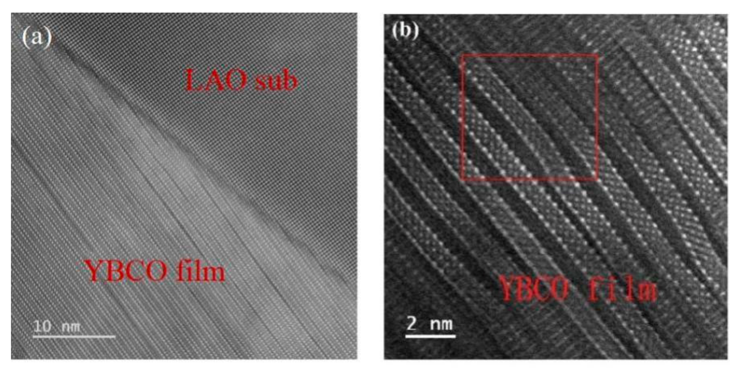
3.1. TEM Analysis of Thin Films on Tilted Substrates

The morphology of the YBa2Cu3O7-δ films on tilted substrates was studied via transmission electron microscopy (TEM), and the results are presented in Figure 1. At a magnification of 6 × 10⁶, Figure 1a shows the typical layered crystal structure of the YBa2Cu3O7-δ thin film. At a higher magnification of 15 × 106 in Figure 1b, the layered crystalline structure of the YBa2Cu3O7-δ thin film is more pronounced. However, the image also reveals the presence of crystal structure defects (shown in red boxes), which are closely linked to the thermal, electrical, and device properties of the film.

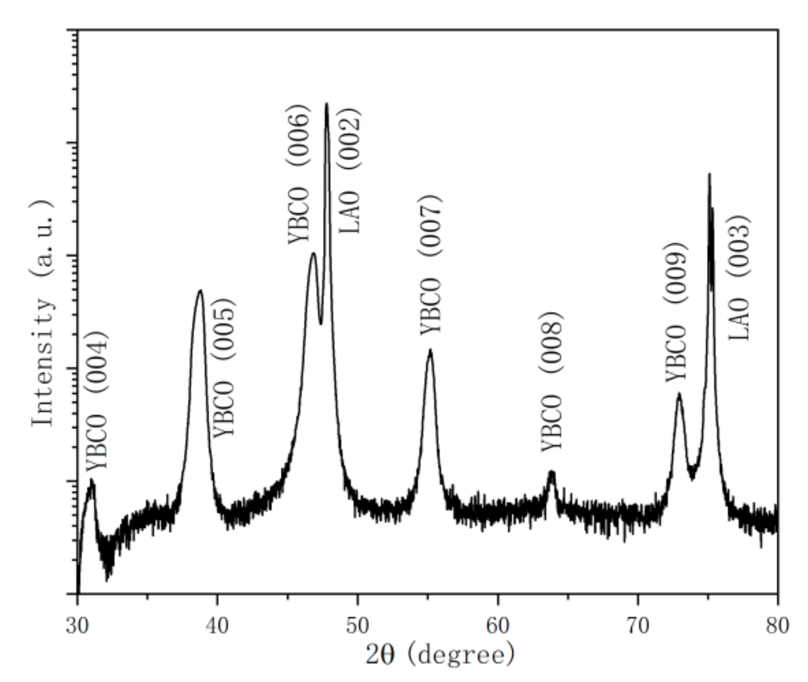
3.2. θ-2θ Linkage Scans of YBa2Cu3O7-δ Thin Films on Tilted Substrates

The X-ray diffraction image of the YBa2Cu3O7-δ thin film is presented in Figure 2. The pattern reveals that the film is highly uniform in orientation and of pure phase. Only (001) crystal plane diffraction peaks of the YBa2Cu3O7-δ film appear, except for the LAO (001) substrate diffraction peak. This indicates that the film is single-phase and strictly (001) oriented, i.e., stacked along the c-axis between the film faces and epitaxially along the c-axis of the substrate [38,39,40]. The relatively sharp diffraction peaks of both the substrate and the film are a positive indication of good crystalline quality.

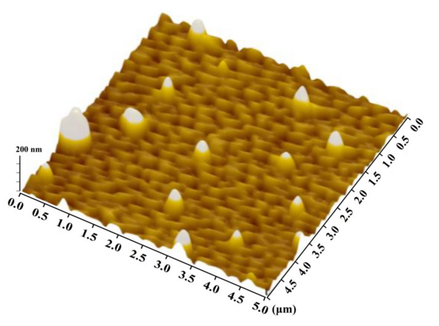
3.3. AFM Morphological Features of Thin Films on Tilted Substrates

The AFM surface morphology of the YBa2Cu3O7-δ/LaAlO3 (001) films on tilted substrates (5 × 5 μm) is presented in Figure 3. The tilted films exhibit a uniform step pattern and uniform orientation in the face with layer-by-layer advancement in the tilted direction, consistent with the step-flux growth mode. Island-like grains are distributed on the step surface. The step width on the substrate surface decreases with the increase in the tilt angle, resulting in a denser step distribution and more sites for preferential inhomogeneous nucleation of the incident incremental particles at the step corners [41,42]. This results in a denser and more homogeneous step pattern compared to films on untilted substrates.

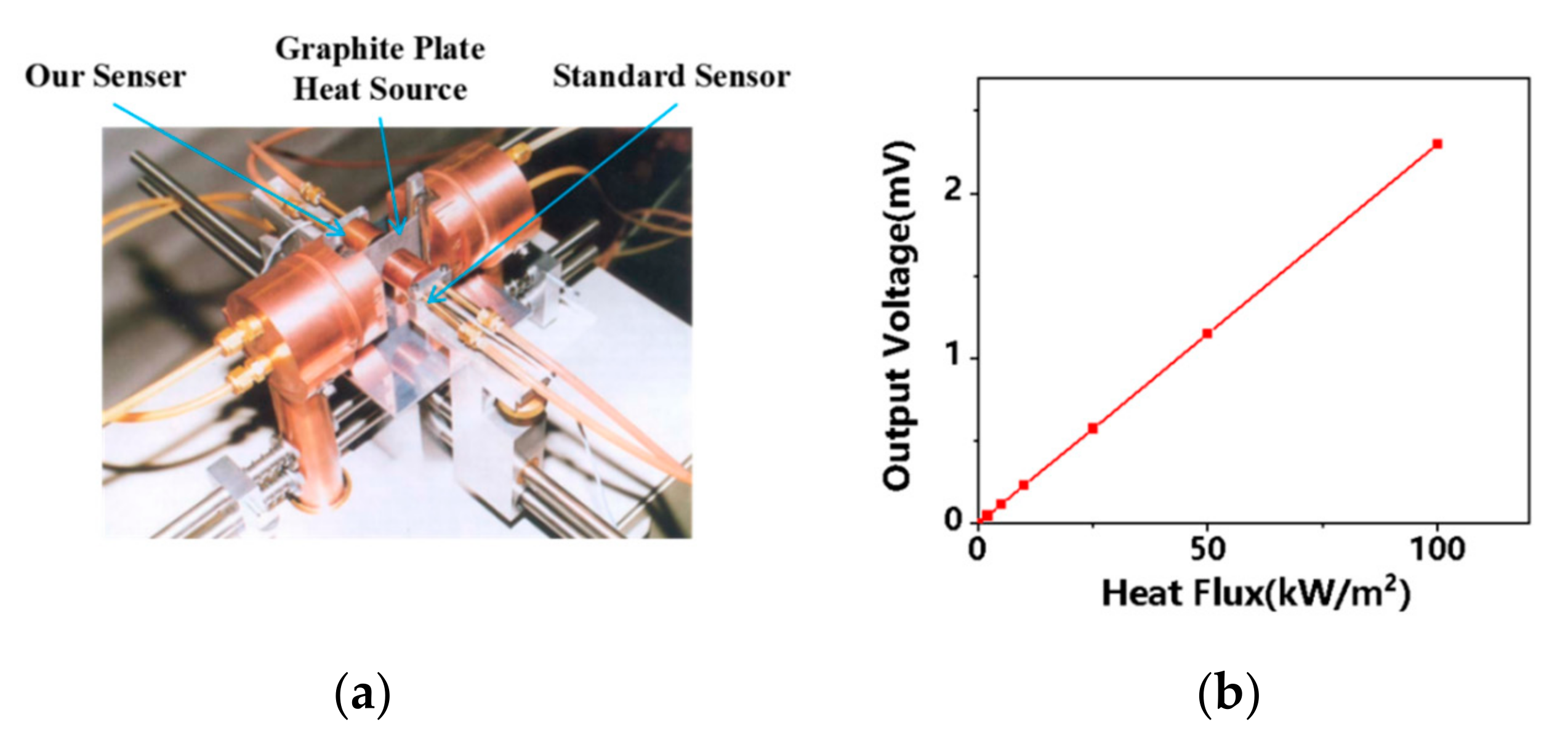
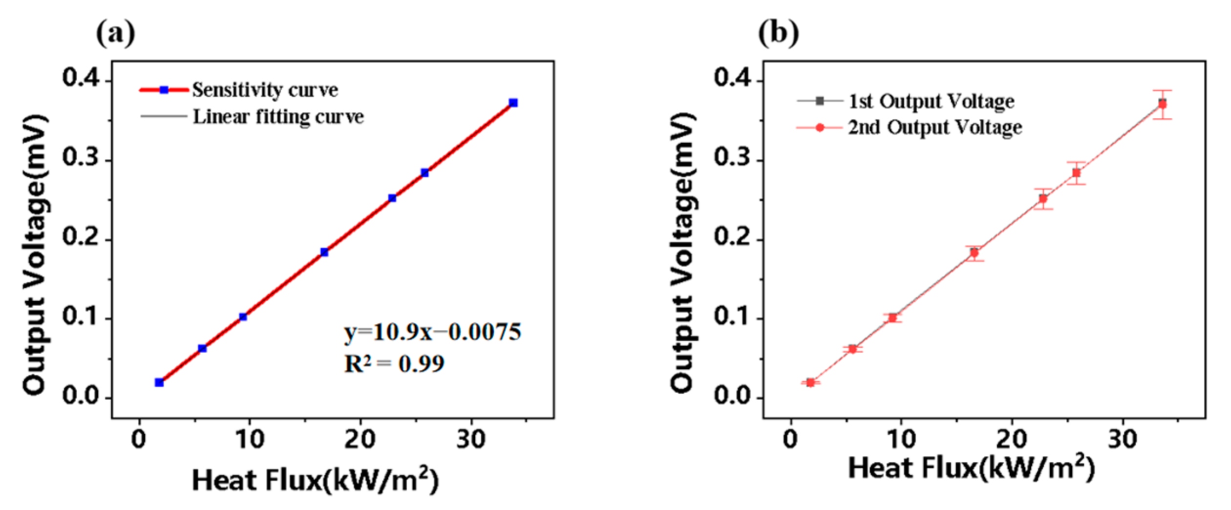
3.4. Calibration of the Devices

In the graphite plate device shown in Figure 4a, the graphite sheet is heated by the water-cooled electrode to reach a high temperature. Two sensors are placed symmetrically on both sides of the graphite sheet. One is a standard sensor calibrated by the absolute method as the reference standard for the test sensor, and the other is a sensor to be calibrated [43,44]. Figure 4b shows the calibration curve of the device within the range of 0~100 kW/m2. It can be seen that the curve shows good consistency, the sensor internal resistance is ~25 Ω, the ambient temperature is 23 ± 3 °C, the relative humidity is <70%, the uncertainty is ±3%, and the sensitivity is 230 μV/(kW/m2). Compared with other similar heat flow sensors, the obvious advantages and improvements of the device we prepared are shown in Table 1. The sensors we designed not only possess high sensitivity, but also high uncertainty. In addition, we also studied the maximum and minimum application range of the device, which greatly improves the application of the device in practical industry.

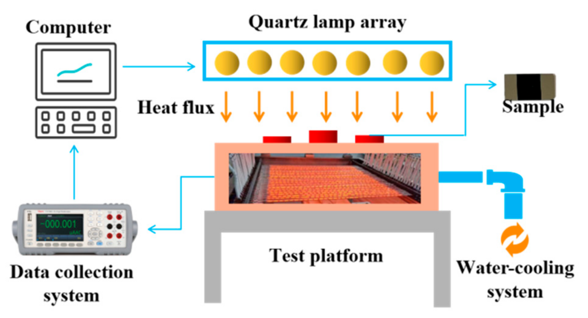
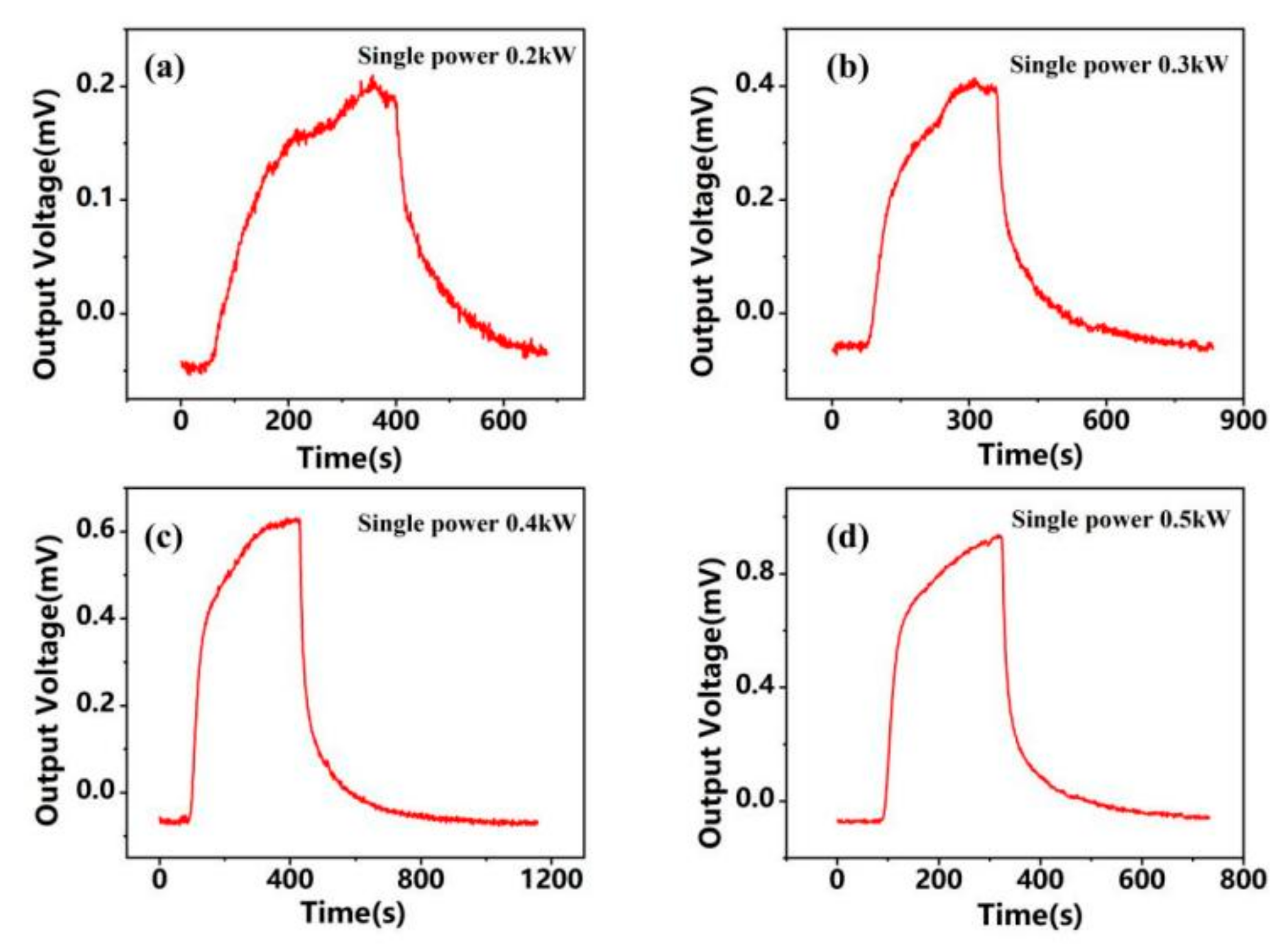
3.5. Steady-State Heat Flux Calibration Facility

The steady-state heat flux calibration facility is depicted in Figure 5. It comprises a quartz lamp array, control system, data acquisition system, and cooling water circulation system. This system provides heat flux densities ranging from 0 to 160 kW/m2, with a control accuracy of 1 kW/m2. The required heat flux density is obtained by adjusting the power of the quartz lamp array, and the prepared heat flux sensitive components are tested for their response and sensitivity. The response test and sensitivity calibration of the prepared heat flux sensitive elements have been performed [45,46,47]. To ensure accurate measurements, the HFS-4 heat flux sensor from OMEGA, Stamford, CT, USA, was used as the standard heat flux sensor. Both the standard heat flux meter and the MEMS thin-film heat flux sensor were mounted symmetrically with the center of the quartz lamp in the middle. The heat flow from the quartz lamp will be directed vertically to the surface of the device. It was assumed that both heat flux sensors measured the same heat flux density, disregarding differences between the quartz lamps and deviation in the measurement position of the two heat flux sensors.
Figure 6a–d illustrate the time-dependent output voltage curve of the heat flux sensitive element when the individual power of the quartz lamp array is 0.2 kW, 0.3 kW, 0.4 kW, and 0.5 kW, respectively. As observed from the graphs, the output voltage initially rises quickly to a maximum value, then decreases gradually before stabilizing. The maximum output voltage values are 0.19 mV, 0.41 mV, 0.63 mV, and 0.94 mV in ascending order.
Figure 7a presents the V-q curve of the output voltage of the element as a function of heat flux. It shows that the output voltage of the designed sensor increases linearly with increasing heat flux density by applying different heat flux densities through the steady-state heat flux calibration facility [48]. The sensitivity of the sensor is obtained through linear fitting and is found to be 10.9 × 10⁻⁶ V/(kW/m2). This sensitivity is almost constant for different heat flux values and temperature environments, as evidenced by a fitted linearity of 0.99. Figure 7b demonstrates the repeatability characteristics of the heat flux sensitive element. It indicates that the element exhibits good repeatability, and the error increases with increasing heat flux density, with a maximum error of only 1.94%.

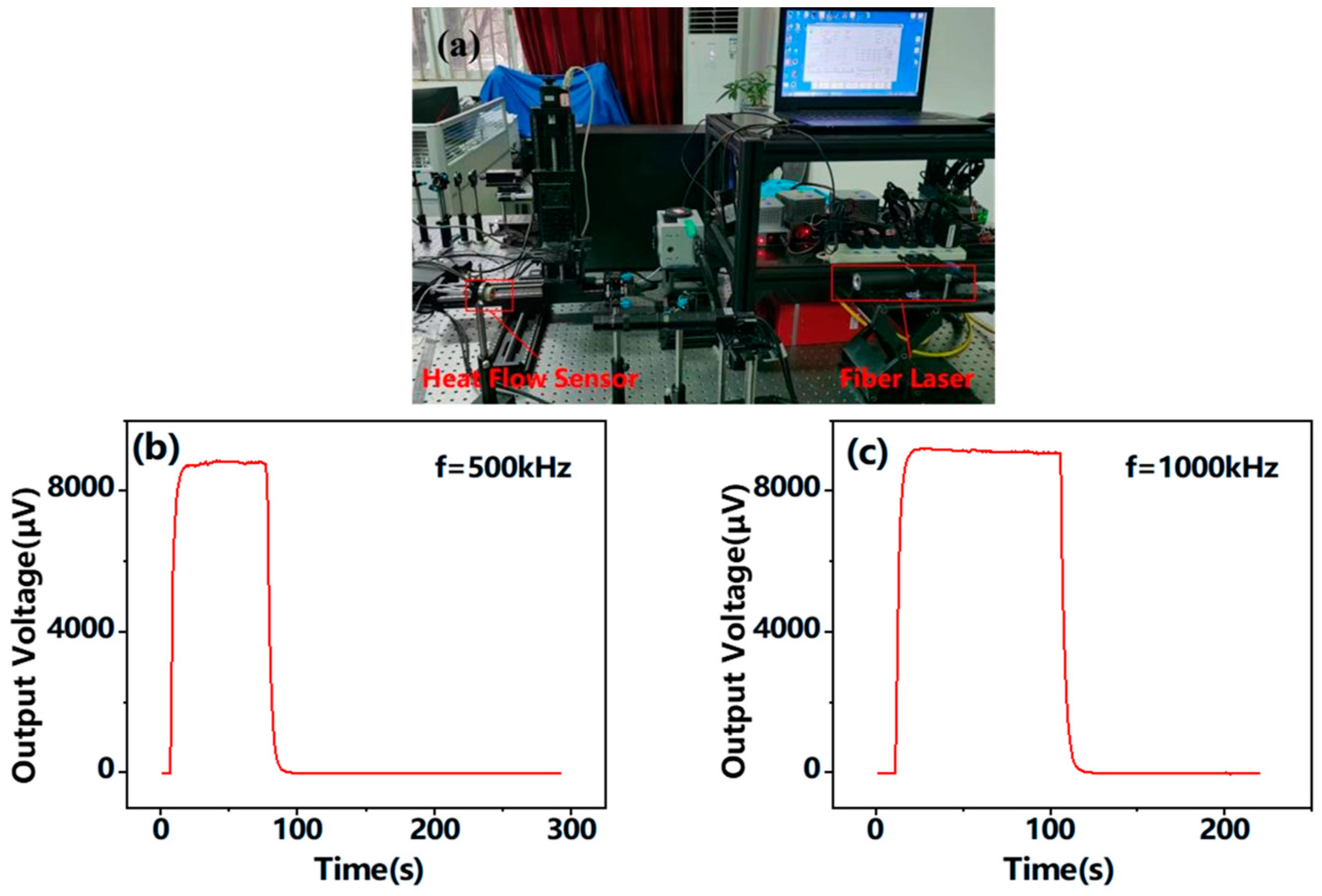
3.6. Transient Heat Flux Calibration Facility

Figure 8a depicts a schematic diagram of the laser-based transient heat flux calibration facility, where a fibre laser serves as the heat flux source and its output is modulated by a voltage signal control module. The laser beam is collimated and focused on the surface of the sensor through an optical system, while the output signal of the heat flux sensor is acquired and processed using a signal conditioning acquisition system [49,50]. The V-T curve for a laser frequency of 500 kHz, set at 6% nominal irradiance, is presented in Figure 8b, and the V-T curve for a sample irradiated at 1000 kHz is shown in Figure 8c. Both figures demonstrate excellent response recovery characteristics.
Figure 9 shows the repeatability curve of the device under irradiation at a laser frequency of 1000 kHz. The YBa2Cu3O7-δ sample exhibited excellent repeatability with a noise of 4.5 μV at room temperature and a maximum voltage output ranging from 7.66 mV to 7.92 mV, as shown in the order of 7.69 mV, 7.73 mV, 7.82 mV, 7.85 mV, 7.87 mV, and 7.90 mV.

3.7. Mechanism Analysis

The heat flux sensitivity properties of YBa2Cu3O7-δ are attributed to its unique layered structure. The structure features alternating stacks of conductive (CuO) and weakly conductive layers (BaO, CuO, and Y layers) along the c-axis direction, resulting in anisotropic thermoelectric transport properties in the interfacial (parallel c-axis) and intrafacial (perpendicular c-axis) directions [51,52,53]. Additionally, the Seebeck effect is present in the anisotropic material, where the adjacent layers can be regarded as a thermocouple pair and their intersection as a thermocouple contact. The layers in the YBa2Cu3O7-δ structure are arranged at intervals, similar to many thermocouple pairs connected in series, thus conferring high sensitivity to heat flux [54,55].
Thermal irradiation of the top surface of YBa2Cu3O7-δ thin-film material generates a temperature gradient along the z-direction, which is perpendicular to the plane of the film. This gradient produces a voltage signal in the x-direction and a transverse thermal potential parallel to the film surface [56,57]. The transverse thermal potential E can be expressed using the Seebeck tensor S and the temperature gradient T as [58]:
E = S T
If the c-axis of the film is not aligned with the temperature gradient direction, the S tensor is transformed by a matrix of the form [59]:
S = S xx 0 S xz 0 S yy 0 S zx 0 S zz = S ab cos 2 α c + S c sin 2 α c 0 sin 2 α c 2 S ab S c 0 S ab 0 sin 2 α c 2 S ab S c 0 S ab sin 2 α c + S c cos 2 α c
The Seebeck tensor components of the crystal in the c-axis and in the ab-plane perpendicular to the c-axis are denoted as Sc and Sab, respectively.
The equation for the peak signal in c-axis tilted epitaxial films is derived from Equations (2) and (3) as [60]:
U x = l 2 d sin ( 2 α c ) S ab S c T z
The effective measurement length along the x-axis is denoted by l, while the sensitive film thickness is represented by d. To generate a transverse voltage signal, the c-axis of the film must not be oriented at an angle of 0° or 90° with respect to the normal [61]. The expression for Ux reveals that increasing the tilt angle θ of the film can boost the transverse voltage signal Ux of the device [62]. In addition, reducing the film thickness d within a certain range can also enhance the voltage Ux by elevating the temperature gradient, while decreasing the thermal capacity of the film can shorten the response time of the device [63]. Consequently, these findings demonstrate that thin-film transverse thermoelectric devices can achieve high sensitivity and fast response times without increasing the device size, thus overcoming the principle that the response sensitivity and response time of conventional thin-film thermo-resistive devices cannot be combined simultaneously [64].
The thin-film transverse thermoelectric effect-based heat flux sensor exhibits high sensitivity, a fast response time, and stable performance at high temperatures, making it an effective solution for achieving ultra-fast heat flux detection. It is capable of meeting the demanding testing requirements of aerospace and high-energy laser fields [65].

4. Conclusions

This study demonstrates that the tilted YBa2Cu3O7-δ films, prepared via PLD technique, exhibit high crystallinity with sharp and strictly (001) oriented diffraction peaks, which is consistent with the step-flow growth mode. The device has ultra-high-sensitivity characteristics in the range from 0 to 100 kW/m2, with the maximum sensitivity of 230 μV/(kW/m2) uncertainty of ±3%, which is significantly better than the similar index. According to the infrared steady-state thermal current calibration system test, when the single output power of the quartz lamp array is 0.2 kW, 0.3 kW, 0.4 kW, and 0.5 kW, the maximum output voltage of the prepared heat current-sensitive element is successively 0.19 mV, 0.41 mV, 0.63 mV, and 0.94 mV, indicating that the sensor output voltage increases with the increase in the heat flow. The sensor demonstrated remarkable response recovery characteristics at both 500 kHz and 1000 kHz fiber-optic laser frequencies. The laser transient heat flux calibration system measured maximum voltage outputs of 8.83 mV and 9.09 mV, respectively. Moreover, the sensor exhibited exceptional repeatability, with a maximum measurement error of 1.94%.

Author Contributions

Conceptualization, H.C., Y.W., Z.Y. and B.T.; data curation, H.C., Z.Y. and X.X.; formal analysis, H.C. and Y.Y.; methodology, H.C., Y.W. and B.D.; software, H.C., Y.W., B.T., Y.Y. and X.X.; writing—original draft preparation, H.C.; writing—review and editing, H.C., Y.W., Z.Y. and X.X. All authors have read and agreed to the published version of the manuscript.

Funding

The authors are grateful for the support of the National Natural Science Foundation of China (11875228); the Project of State Key Laboratory of Environmentally friendly Energy Materials, Southwest University of Science and Technology (No. 20fksy23, 21fksy27, 22fksy26).

Institutional Review Board Statement

Not applicable.

Informed Consent Statement

Not applicable.

Data Availability Statement

Publicly available datasets were analyzed in this study. These data can be found here: [https://www.lumerical.com/ (accessed on 1 January 2020)].

Conflicts of Interest

The authors declare no conflict of interest.

References

  1. Chen, L.; Cheng, M.; Hong, W. Ablationthermal-structure test of large scale model in 1 m arc heated wind tunnel. Aerosp. Mater. Technol. 2009, 6, 71–73. [Google Scholar]
  2. Zhang, L.; Sheng, Z.; Dan, Y. Effects of sawtooth grooves on supersonic combustion. Aerosp. Sci. Technol. 2023, 136, 108223. [Google Scholar] [CrossRef]
  3. Chen, H.; Li, W.; Zhu, S.; Hou, A.; Liu, T.; Xu, J.; Zhang, X.; Yi, Z.; Yi, Y.; Dai, B. Study on the Thermal Distribution Characteristics of a Molten Quartz Ceramic Surface under Quartz Lamp Radiation. Micromachines 2023, 14, 1231. [Google Scholar] [CrossRef] [PubMed]
  4. Raghavendra, M.; Amba, G.; Kumar, A. Experimental validation of liquid hydrocarbon based fuel rich gas generator for high speed propulsion systems. Acta Astronaut. 2020, 174, 180–188. [Google Scholar] [CrossRef]
  5. Gao, S.Y.; Wei, K.H.; Yang, H.; Tang, Y.J.; Yi, Z.; Tang, C.J.; Tang, B.; Yi, Y.G.; Wu, P.H. Design of Surface Plasmon Reso-nance-Based D-Type Double Open-Loop Channels PCF for Temperature Sensing. Sensors 2023, 23, 7569. [Google Scholar] [CrossRef] [PubMed]
  6. Li, J.; Liu, G.; Liu, B.; Min, Z.; Qian, D.; Jiang, J.; Li, J. An extremely facile route to Co2P encased in N,P-codoped carbon layers: Highly efficient bifunctional electrocatalysts for ORR and OER. Int. J. Hydrogen Energy 2018, 3, 1365–1374. [Google Scholar] [CrossRef]
  7. Jin, X.; Ma, B.; Qiu, T.; Deng, J.; Luo, J. Temperature and heat flux measurement technologies in scramjet. J. Exp. Fluid Mech. 2018, 32, 74–81. [Google Scholar]
  8. Zhang, W.; Zeng, M.; Xiao, L. Numerical study for the effects of ablation and pyrolysis on the hypersonic reentry flow. J. Natl. Univ. Def. Technol. 2014, 36, 41–48. [Google Scholar]
  9. Schneider, S. Developing mechanism-based methods forestimating hypersonic boundary-layer transition in flight: Therole of quiet tunnels. Prog. Aerosp. Sci. 2015, 72, 17–29. [Google Scholar] [CrossRef]
  10. Duan, L.; Zhou, H.; Xu, W.; Li, L.; Liu, X.; Du, Z.; Jiang, H. Design method of multiple inlet/outlet air cooling frame of pouch lithium-ion battery based on thermal-fluid coupling topology optimization. Int. J. Heat Mass Transf. 2023, 215, 124496. [Google Scholar] [CrossRef]
  11. Ji, F.; Xie, S.; Shen, Q. Hypersonic high frequency (1MHz) fluctuation pressure testing technology and application. Acta Aerodyn. Sin. 2016, 34, 587–591. [Google Scholar]
  12. Zhang, C.; Yao, Z.; Qin, J.; Bao, W. Experimental study on measurement and calculation of heat flux in supersonic combustor of scramjet. J. Therm. Sci. 2015, 24, 254–259. [Google Scholar] [CrossRef]
  13. Mersinligil, M.; Desset, J.; Brouckaert, J. High-temperature high-frequency turbine exit flow fieldmeasurements in a military engine with a cooled unsteady total pressure probe. Proc. Inst. Mech. Eng. Part A J. Power Energy 2011, 225, 954–963. [Google Scholar] [CrossRef]
  14. Chen, H.; Liu, T.; Feng, N.; Shi, Y.; Zhou, Z.; Dai, B. Structural Design of Dual-Type Thin-Film Thermopiles and Their Heat Flow Sensitivity Performance. Micromachines 2023, 14, 1458. [Google Scholar] [CrossRef]
  15. Xie, H.; Zhang, L.; Li, X.; Li, S.; Hao, Z.; Wang, H.; Xiong, J.; Tan, Q. Design, Preparation, and Performance Study of a Miniaturized High-Temperature Thick-Film Heat Flux Sensor. IEEE Sens. J. 2023, 23, 11420–11427. [Google Scholar] [CrossRef]
  16. Cui, Y.; Liu, H.; Wang, H.; Guo, S.; E, M.; Ding, W.; Yin, J. Design and Fabrication of a Thermopile-Based Thin Film Heat Flux Sensor, Using a Lead—Substrate Integration Method. Coatings 2022, 12, 1670. [Google Scholar] [CrossRef]
  17. Fang, J.; Zhang, C. Study on unsteady heat transfer of heat flux sensor based on Abaqus. Chin. J. Sci. Instrum. 2018, 39, 152–161. [Google Scholar]
  18. Zhang, X.; Meng, X.; Wang, K. Study of Calibration Device on Heat Flux Sensor of the Thermal Resistance Mode. J. Astronaut. Metrol. Meas. 2020, 40, 15–19. [Google Scholar]
  19. Yang, Q.; Zeng, H.; Wang, H.; Zhu, X. Atomic Layer Thermopile Heat Flux Sensor and Its Application in Aerodynamics Tests. Tactical Missile Technol. 2015, 91, 37–41. [Google Scholar]
  20. Li, Z.; Wang, G.; Yin, J.; Xue, H.; Guo, J.; Wang, Y.; Huang, M. Development and Performance Analysis of an Atomic Layer Thermopile Sensor for Composite Heat Flux Testing in an Explosive Environment. Electronics 2023, 12, 3582. [Google Scholar] [CrossRef]
  21. Wang, Y.; Yu, L.; Zhang, P. Transverse thermoelectric response in tilted orientation La1−xSrxCoO3(0.05 ≤ x ≤ 0.4) thin films. J. Appl. Phys. 2011, 110, 1–5. [Google Scholar] [CrossRef]
  22. Qin, Y.; Zhao, T.; Wang, B. Development of a transverse thermoelectric voltage effect in artificial SrTiO3/SrTi1-xNbxO3 epitaxial multilayer films with incline-oriented sublayers. Cryst. Eng. Comm. 2014, 16, 5345–5351. [Google Scholar] [CrossRef]
  23. Lengfellner, H.; Kremb, G.; Schnellbgl, A.; Betz, J.; Renk, K.; Prettl, W. Giant voltages upon surface heating in normal YBa2Cu3O7-δ films suggesting an atomic layer thermopile. Appl. Phys. Lett. 1992, 60, 501. [Google Scholar] [CrossRef]
  24. Jenkins, S.; Wolfersdorf, J.; Weigand, B.; Roediger, T.; Knauss, H.; Kraemer, E. Time-Resolved Heat Transfer Measurements on the Tip Wall of a Ribbed Channel Using a Novel Heat Flux Sensor-Part Ⅱ: Heat Transfer Results. J. Turbomach. 2008, 130, 011019. [Google Scholar] [CrossRef]
  25. Zhang, P.; Habermeier, H. Atomic layer thermopile materials: Physics and application. J. Nanomater. 2008, 67, 1–12. [Google Scholar] [CrossRef]
  26. Chen, X.; Tao, B.; Zhao, R.; Yang, K.; Xia, Y.; Li, Z.; Xie, T.; Zhong, Y.; Zhang, T. High-frequency response heat flux sensor based on the transverse thermoelectric effect of inclined La1−xCaxMnO3 films. Appl. Phys. Lett. 2022, 121, 204102. [Google Scholar] [CrossRef]
  27. Mityakov, A.; Sapozhnikov, S.; Mityakov, V. Gradient heat flux sensors for high temperature environments. Sens. Actuators A Phys. 2012, 176, 1–9. [Google Scholar] [CrossRef]
  28. Song, S.; Wang, Y.; Yu, L. Highly sensitive heat flux sensor based on the transverse thermoelectric effect of YBa2Cu3O7-δ thin film. Appl. Phys. Lett. 2020, 117, 123902. [Google Scholar] [CrossRef]
  29. Zahner, T.; Förg, R.; Lengfellner, H. Transverse thermoelectric response of a tilted metallic multilayer structure. Appl. Phys. Lett. 1998, 73, 1364–1366. [Google Scholar] [CrossRef]
  30. Wang, X.; Liu, X.C. Process Research of Ca3Co4O9 Thermoelectric Materials. Piezoelectrics Acoustooptics 2019, 41, 275–284. [Google Scholar]
  31. Wang, S.; Chen, S.; Liu, F.; Yan, G.; Chen, J.; Li, H.; Wang, J.; Yu, W.; Fu, G. Laser-induced voltage effects in c-axis inclined NaxCoO2 thin films. Appl. Surf. Sci. 2012, 258, 7330–7333. [Google Scholar] [CrossRef]
  32. Shao, T.; Yu, L.; Zhang, P. Research on Laser Induced Voltage Effect in Polycrystalline YBa2Cu3O7-δ Bulk. Mater. Heat Treat. 2012, 41, 28–31. [Google Scholar]
  33. Song, S.; Yu, L.; Hu, J.; Liu, A.; Zhong, Y. Laser-induced transverse voltage effect and thermopower anisotropy of c-axis inclined Ca3Co4O9 thin film. Appl. Phys. A 2017, 123, 1–8. [Google Scholar] [CrossRef]
  34. Guo, M.; Li, J.; Jia, J. Growth of YBa2Cu3O7-δ superconducting films under different atmospheres by pulsed laser deposition. Phys. C Supercond. Its Appl. 2023, 605, 1354206. [Google Scholar] [CrossRef]
  35. Liang, S.R.; Xu, F.; Li, W.X.; Yang, W.X.; Cheng, S.B.; Yang, H.; Chen, J.; Yi, Z.; Jiang, P.P. Tunable smart mid infrared thermal control emitter based on phase change material VO2 thin film. Appl. Therm. Eng. 2023, 232, 121074. [Google Scholar] [CrossRef]
  36. Liu, W.; Liu, C.; Wang, J.X.; Lv, J.W.; Lv, Y.; Yang, L.; An, N.; Yi, Z.; Liu, Q.; Hu, C.J.; et al. Surface plasmon resonance sensor composed of microstructured optical fibers for monitoring of external and internal environments in biological and environmental sensing. Results Phys. 2023, 47, 106365. [Google Scholar] [CrossRef]
  37. Li, C.; Shi, X.; Liang, S.; Ma, X.; Han, M.; Wu, X.; Zhou, J. Spatially homogeneous copper foam as surface dendrite-free host for zinc metal anode. Chem. Eng. J. 2020, 379, 122248. [Google Scholar] [CrossRef]
  38. Zhu, Y.Y.; Cai, P.G.; Zhang, W.L.; Meng, T.Y.; Tang, Y.J.; Yi, Z.; Wei, K.H.; Li, G.F.; Tang, B.; Yi, Y.G. Ultra-Wideband High-Efficiency Solar Absorber and Thermal Emitter Based on Semiconductor InAs Microstructures. Micromachines 2023, 14, 1597. [Google Scholar] [CrossRef]
  39. Zhang, Y.; Pu, M.; Jin, J.; Lu, X.; Guo, Y.; Cai, J.; Zhang, F.; Ha, Y.; He, Q.; Xu, M.; et al. Crosstalk-free achromatic full Stokes imaging polarimetry metasurface enabled by polarization-dependent phase optimization. Opto-Electron. Adv. 2022, 5, 220058. [Google Scholar] [CrossRef]
  40. Wu, X.; Yin, C.; Zhang, M.; Xie, Y.; Hu, J.; Long, R.; Wu, X.; Wu, X. The Intercalation Cathode of MOFs-driven Vanadium-based Composite Embedded in N-doped Carbon for Aqueous Zinc ion Batteries. Chem. Eng. J. 2023, 452, 139573. [Google Scholar] [CrossRef]
  41. Qin, F.; Chen, J.; Liu, J.W.; Liu, L.; Tang, C.J.; Tang, B.; Li, G.F.; Zeng, L.C.; Li, H.L.; Yi, Z. Design of high efficiency perovskite so-lar cells based on inorganic and organic undoped double hole layer. Sol. Energy 2023, 262, 111796. [Google Scholar] [CrossRef]
  42. Shan, L.; Zhou, J.; Zhang, W.; Xia, C.; Guo, S.; Ma, X.; Fang, G.; Wu, X.; Liang, S. Highly Reversible Phase Transition Endows V6O13 with Enhanced Performance as Aqueous Zinc-Ion Battery Cathode. Energy Technol. 2019, 7, 57. [Google Scholar] [CrossRef]
  43. Chen, Z.H.; Cai, P.G.; Wen, Q.Y.; Chen, H.; Tang, Y.J.; Yi, Z.; Wei, K.H.; Li, G.F.; Tang, B.; Yi, Y.G. Graphene Multi-Frequency Broadband and Ultra-Broadband Terahertz Absorber Based on Surface Plasmon Resonance. Electronics 2023, 12, 2655. [Google Scholar] [CrossRef]
  44. Meng, W.; Li, C.; Yao, M.; He, Z.; Wu, X.; Jiang, Z.; Dai, L.; Wang, L. Synthesis and electrochemical performance of Li1+xTi2−xFex(PO4)3/C anode for aqueous lithium ion battery. Adv. Powder Technol. 2020, 31, 1359–1364. [Google Scholar] [CrossRef]
  45. Serpetzoglou, E.; Konidakis, I.; Kourmoulakis, G.; Demeridou, I.; Chatzimanolis, K.; Zervos, C.; Kioseoglou, G.; Kymakis, E.; Stratakis, E. Charge carrier dynamics in different crystal phases of CH3NH3PbI3 perovskite. Opto-Electron. Sci. 2022, 1, 210005. [Google Scholar] [CrossRef]
  46. Wu, X.; Li, Y.; Xiang, Y.; Liu, Z.; He, Z.; Wu, X.; Li, Y.; Xiong, L.; Li, C.; Chen, J. The electrochemical performance of aqueous re-chargeable battery of Zn/Na0.44MnO2 based on hybrid electrolyte. J. Power Sources 2016, 336, 35–39. [Google Scholar] [CrossRef]
  47. Zheng, Y.; Yi, Z.; Liu, L.; Wu, X.W.; Liu, H.; Li, G.F.; Zeng, L.C.; Li, H.L.; Wu, P.H. Numerical simulation of efficient solar ab-sorbers and thermal emitters based on multilayer nanodisk arrays. Appl. Therm. Eng. 2023, 230, 120841. [Google Scholar] [CrossRef]
  48. Wu, X.; Li, Y.; Xiang, Y.; Liu, Z.; He, Z.; Wu, X.; Li, Y.; Xiong, L.; Li, C.; Chen, J. Mixed-valence cobalt oxides bifunctional electro-catalyst with rich oxygen vacancies for aqueous metal-air batteries. Chem. Eng. J. 2023, 453, 139831. [Google Scholar] [CrossRef]
  49. Wu, F.Y.; Shi, P.C.; Yi, Z.; Li, H.L.; Yi, Y.G. Ultra-Broadband Solar Absorber and High-Efficiency Thermal Emitter from UV to Mid-Infrared Spectrum. Micromachines 2023, 14, 985. [Google Scholar] [CrossRef]
  50. Wu, X.W.; Li, Y.H.; Li, C.C.; He, Z.X.; Xiang, Y.H.; Xiong, L.Z.; Chen, D.; Yu, Y.; Sun, K.; He, Z.Q.; et al. The electrochemical performance improvement of LiMn2O4/Zn based on zinc foil as the current collector and thiourea as an electrolyte additive. J. Power Sources 2015, 300, 453–459. [Google Scholar] [CrossRef]
  51. Crommie, M.; Zettl, A.; Cohen, M. Anisotropic thermoelectric power and conductivity in single-crystal YBa2Cu3O7-δ. Phys. Rev. B 1988, 37, 9734–9738. [Google Scholar] [CrossRef] [PubMed]
  52. Yamasaki, H. Temperature dependence of the self-field critical current densities and flux pinning in YBa2Cu3O7–δ thin films containing nanoprecipitates. Phys. C Supercond. Its Appl. 2022, 597, 1354063. [Google Scholar] [CrossRef]
  53. Zou, P.; Lv, D.; Zhang, H.; Li, Z. Preparation and Laser-Induced Thermoelectric Voltage Effect of Bi2Sr2Co2Oy Thin Films Grown on Al2O3 (0001) Substrate. Materials 2023, 16, 5165. [Google Scholar] [CrossRef]
  54. Tang, F.; Wu, X.; Shen, Y.; Xiang, Y.; Wu, X.; Xiong, L.; Wu, X. The intercalation cathode materials of heterostructure MnS/MnO with dual ions defect embedded in N-doped carbon fibers for aqueous zinc ion batteries. Energy Storage Mater. 2022, 52, 180–188. [Google Scholar] [CrossRef]
  55. Lai, R.; Shi, P.; Yi, Z.; Li, H.; Yi, Y. Triple-Band Surface Plasmon Resonance Metamaterial Absorber Based on Open-Ended Prohib-ited Sign Type Monolayer Graphene. Micromachines 2023, 14, 953. [Google Scholar] [CrossRef] [PubMed]
  56. Li, Y.; Yang, S.; Du, H.; Liu, Y.; Wu, X.; Yin, C.; Wang, D.; Wu, X.; He, Z.; Wu, X. A stable fluoride-based interphase for a long cycle Zn metal anode in an aqueous zinc ion battery. J. Mater. Chem. A 2022, 10, 14399–14410. [Google Scholar] [CrossRef]
  57. Lengfellner, H.; Zeuner, S.; Prettl, W. Thermoelectric effect in normal-state YBa2Cu3O7-δ films. Europhys. Lett. 1994, 25, 375–383. [Google Scholar] [CrossRef]
  58. Krasikov, S.; Tranter, A.; Bogdanov, A.; Kivshar, Y. Intelligent metaphotonics empowered by machine learning. Opto-Electron. Adv. 2022, 5, 210147. [Google Scholar] [CrossRef]
  59. Zhu, L.; Hu, R.; Xiang, Y.; Yang, X.; Chen, Z.; Xiong, L.; Wu, X.; He, Z.; Lei, W. Enhanced performance of Li-S battery by con-structing inner conductive network and outer adsorption layer sulfur-carbon composite. Int. J. Energy Res. 2020, 45, 6002–6014. [Google Scholar] [CrossRef]
  60. Wang, Z.; Liu, Y.; Li, L.; Gao, S.; Zhu, D.; Yu, X.; Cheng, S.; Zheng, D.; Xiong, Y. An investigation of the effects of ZnO inverse opal pore size in the composite of ZnO nanorods/ZnO inverse opal on the performance of quantum dot-sensitized solar cells. Dalton Trans. 2023, 52, 81–89. [Google Scholar] [CrossRef]
  61. Wu, X.; Tan, C.; He, C.; Zhao, T.; Wu, X.; Ma, Z.; Wang, H.; Cai, Y.; Wu, Q.; Li, Q. Strategy for boosting Co-Nx content for oxygen reduction reaction in aqueous metal-air batteries. J. Power Sources 2022, 520, 230891. [Google Scholar] [CrossRef]
  62. Liu, Y.; Wang, Z.; Li, L.; Gao, S.; Zheng, D.; Yu, X.; Wu, Q.; Yang, Q.; Zhu, D.; Yang, W.; et al. Highly efficient quan-tum-dot-sensitized solar cells with composite semiconductor of ZnO nanorod and oxide inverse opal in photoanode. Electrochim. Acta 2022, 412, 140145. [Google Scholar] [CrossRef]
  63. Kim, M.K.; Lee, D.S.; Yang, Y.H.; Rho, J.S. Switchable diurnal radiative cooling by doped VO2. Opto-Electron. Adv. 2021, 4, 200006. [Google Scholar] [CrossRef]
  64. Zhou, W.; Qin, X.; Lv, M.; Qiu, L.; Chen, Z.; Zhang, F. Design of a New Type of In-Hole Gold-Coated High-Performance Quasi-PCF Sensor Enhanced with Surface Plasmon Resonance. Coatings 2023, 13, 1261. [Google Scholar] [CrossRef]
  65. Fahey, T.; Islam, M.; Gardi, A.; Sabatini, R. Laser Beam Atmospheric Propagation Modelling for Aerospace LIDAR Applications. Atmosphere 2021, 12, 918. [Google Scholar] [CrossRef]
Figure 1. High-resolution-transmission electron microscopy image of YBa2Cu3O7-δ thin film on LaAlO3 single-crystal substrate, (a) 6 × 10⁶ magnification image, (b) 15 × 106 magnification image.
Coatings 13 01610 g001
Figure 2. XRD θ-2θ scan pattern of YBa2Cu3O7-δ/LaAlO3 (001)/15° film.
Coatings 13 01610 g002
Figure 3. AFM images (5 × 5 μm) of YBa2Cu3O7-δ/LaAlO3 (001) film with tilted angle 15° film.
Coatings 13 01610 g003
Figure 4. (a) is a schematic diagram of the device calibration test system by graphite flat plate heating method, and (b) is the calibration curve of the device in the range of 0~100 kW/m2.
Coatings 13 01610 g004
Figure 5. Schematic diagram of steady-state heat flow calibration facility. The arrows represent the vertical transfer of heat flow to the sensor surface, which we have illustrated by marking the red position.
Coatings 13 01610 g005
Figure 6. (ad) show the V-T variation curve of the output of the heat flow sensor when the power of a single quartz lamp array is 0.2 kW, 0.3 kW, 0.4 kW and 0.5 kW, respectively.
Coatings 13 01610 g006
Figure 7. (a) The output V-q curve of the heat flow sensor, (b) the repeated characteristic curve of the heat flow sensor.
Coatings 13 01610 g007
Figure 8. (a) The schematic diagram of the laser transient heat flow calibration facility, (b) the V-T dynamic curve under the irradiation of the laser frequency of 500 kHz, (c) the V-T dynamic curve under the irradiation of the sample laser frequency of 1000 kHz.
Coatings 13 01610 g008
Figure 9. Repetition response curve of the component under 1000 kHz laser frequency irradiation.
Coatings 13 01610 g009
Table 1. Comparison of the sensitivity and uncertainty of our designed sensor with other similar sensors.
References[8][16][20][26]This Work
Sensitivity (μV/(kW/m2))127607.1214.25230
Uncertainty (%)--4-±3
Resistance (Ω)291---25
Measuring Range (kW/m2)----1 × 102~2 × 10⁵
Disclaimer/Publisher’s Note: The statements, opinions and data contained in all publications are solely those of the individual author(s) and contributor(s) and not of MDPI and/or the editor(s). MDPI and/or the editor(s) disclaim responsibility for any injury to people or property resulting from any ideas, methods, instructions or products referred to in the content.

