1. Introduction
The evolution of humankind is associated with the use of materials and tools to such an extent that the phases of human civilization are named after the engineering materials of the age. Part of the reason for this is that materials define the operating limit of key engineering components. A prime example is the material chosen for the nuclear fuel element cladding in a nuclear reactor, which largely determines the operating conditions. As the nuclear industry continues to advance, new materials are needed to satisfy the strict operational and safety requirements needed for the safe operation of a nuclear power plant.
Nowadays, there is an urgent need to reduce greenhouse gases (GHGs) worldwide as part of climate change policies to limit global warming. These policies are encouraging the phase-out of fossil-fired plants and transitioning to non-GHG-emitting sources of energy, such as nuclear. Among others, these policies created an environment to revive SMR concepts, as these meet several targets in terms of costs and financial risk reductions while reducing our dependency on fossil fuels. Furthermore, several international programs have been established to support the advancement of advanced nuclear reactors. Among them, the Generation IV International Forum (GIF) was established in 2001. The GIF identified six technologies as potential Generation-IV concepts, namely: gas-cooled fast reactors (GFRs), very-high-temperature reactors (VHTRs), molten salt reactors (MSRs), sodium-cooled fast reactors (SFRs), lead-cooled fast reactors (LFRs), and supercritical water-cooled reactors (SCWRs) [
1,
2]. Currently, the vast majority of SMR concepts are based on these technologies.
Canadian Nuclear Laboratories (CNL) has supported Canada’s participation in the Generation IV International Forum through the development of the Canadian SCWR concept [
3]. This concept aims to produce 1200 MWe. As Canada is aiming to become a leader in SMR technology [
4], the configuration of the Canadian SCWR concept has been scaled down to assess the feasibility of a supercritical water-cooled small modular reactor (SCW-SMR). This technology was chosen because SCW-SMRs are in a good position to replace old fossil-fired plants of ~300 MWe, as several components can be salvaged, thus potentially reducing the construction costs.
Generation-IV water-cooled reactors, such as supercritical water-cooled reactors, operate at higher temperatures than the current water-cooled reactors to increase the thermodynamic efficiency of the plant, which translates to more electricity produced for the same amount of fuel burnup. However, there is a limit on the maximum operating temperature, which is limited by the material’s properties. Of particular interest is the fuel cladding, as this component contains the nuclear fuel and acts as a safety barrier against the potential release of fission products from the fuel to the coolant. The selection of the cladding candidate demands a multidisciplinary approach as there are multiple constraints that need to be satisfied. These constraints can be grouped into three major categories, namely: (1) performance, (2) safety, and (3) economics [
5]. The first one deals with the operational requirements of the component, such as a low-absorption cross-section (for neutron economy), corrosion resistance, and a reliable operating life. It must also provide safety functions, such as allowing for proper core cooling, and should confine the radioactive material. Finally, the costs of the cladding should be competitive, or the overall gains must at least offset the current cladding material to be economically justifiable.
Given these requirements, a chromium-coated zirconium alloy was proposed as a potential candidate for use in an SCW-SMR. Chromium coatings up to a few micrometers have imparted promising oxidation resistance improvements to zirconium-based cladding under operating conditions relevant to SCW-SMR concepts [
6,
7,
8,
9,
10,
11].
In this study, Zr-2.5Nb alloy (UNS R60904) samples machined from a pressure tube were coated using a physical vapor-deposition (PVD) method. Oxidation testing was performed on the coated samples at 500 °C and approximately 25 MPa in a refreshed autoclave.
This approach focuses on the performance of a chromium-coated zirconium alloy from a corrosion resistance point of view. In addition, a review of the current status of the effect of corrosion on the performance and safety of the cladding and heat transfer is presented. Finally, to understand the constraint of economics on fuel cladding, a cost model is established to estimate and analyze the costs associated with coating this cladding material with chromium in a vacuum plasma spray (VPS) process.
2. Materials and Methods
Zircaloy is currently used as a preferred fuel cladding material in the majority of commercial nuclear power plants, as it meets the current requirements and operation conditions. However, Zircaloy degrades under supercritical water conditions. For that reason, a chromium-coated zirconium alloy was considered as a potential cladding material for SCW-SMRs.
2.1. Zr-Based Alloy: Sample Preparation
Details of the materials selected for this study are listed in
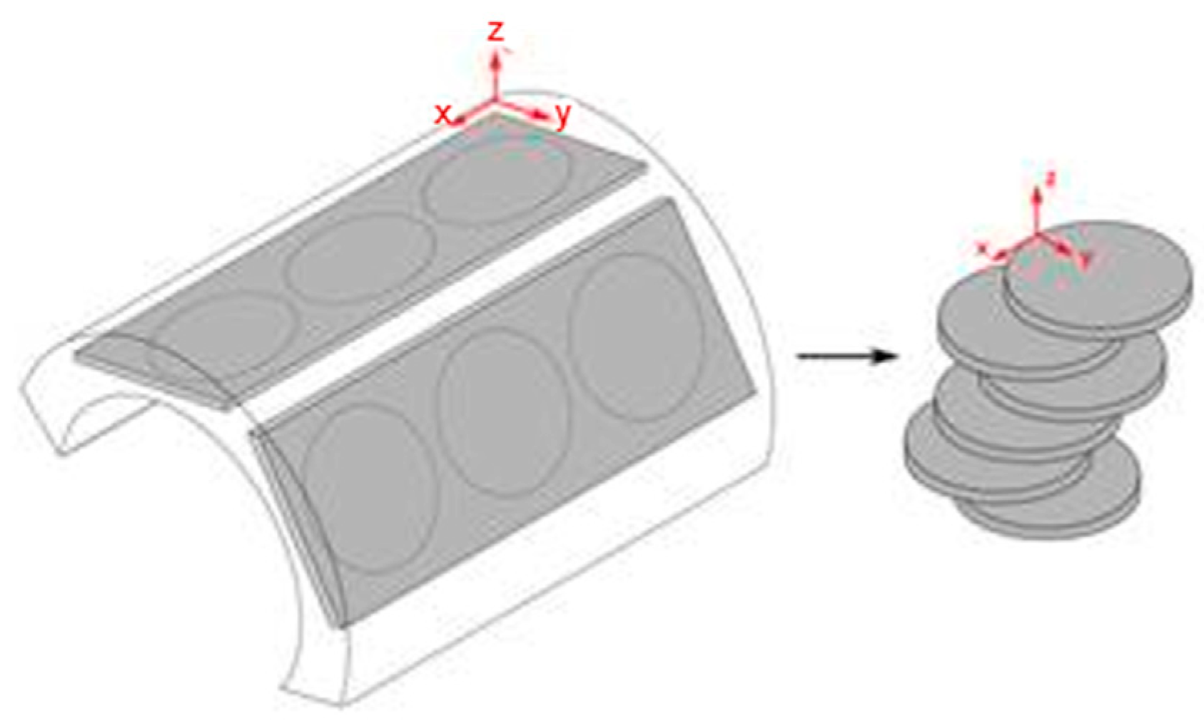
Table 1. Disk-shaped coupons with a nominal diameter of 22 to 25 mm and nominal thickness of 3 to 4 mm were machined from a Zr-2.5Nb W087 pressure tube wall with the largest surface area parallel to the rolling/extrusion direction. A simplified diagram showing coupon cutting is shown in
Figure 1. Each coupon was stamped with an alloy designation and a serial number. The surfaces of the coupons were first polished using 360-grit SiC paper, followed by 600-grit SiC paper. The coupons were then rinsed and washed in an ultrasonic bath of acetone, followed by isopropyl alcohol to degrease the surfaces.
2.2. Surface Coating via Physical Vapor Deposition
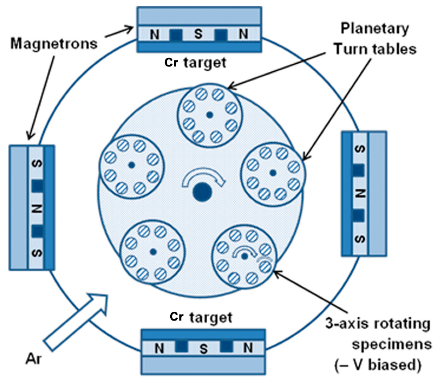
Chromium coating was conducted by the Canadian National Research Council (NRC) in an unbalanced closed-field magnetron sputtering (UMS) physical vapor-deposition (PVD) coater (Teer 650) (see
Figure 2). Argon was used as a working gas to produce plasma for metal-target sputtering. A chromium target of more than 99.5% purity was used. The deposition chamber was depressurized to below 7 × 10
−3 Pa (5 × 10
−5 Torr) before the introduction of the working gas. The samples were cleaned with isopropyl alcohol prior to insertion into the chamber. The planetary turning tables were rotated in the x–y–z directions during deposition, resulting in a uniform coating on the sample surfaces. A direct current (DC) of 6 A was applied to the target. A pulsed DC bias voltage of −40 V was applied to the substrate. The deposition rate was determined to be about 2.46 µm/h.
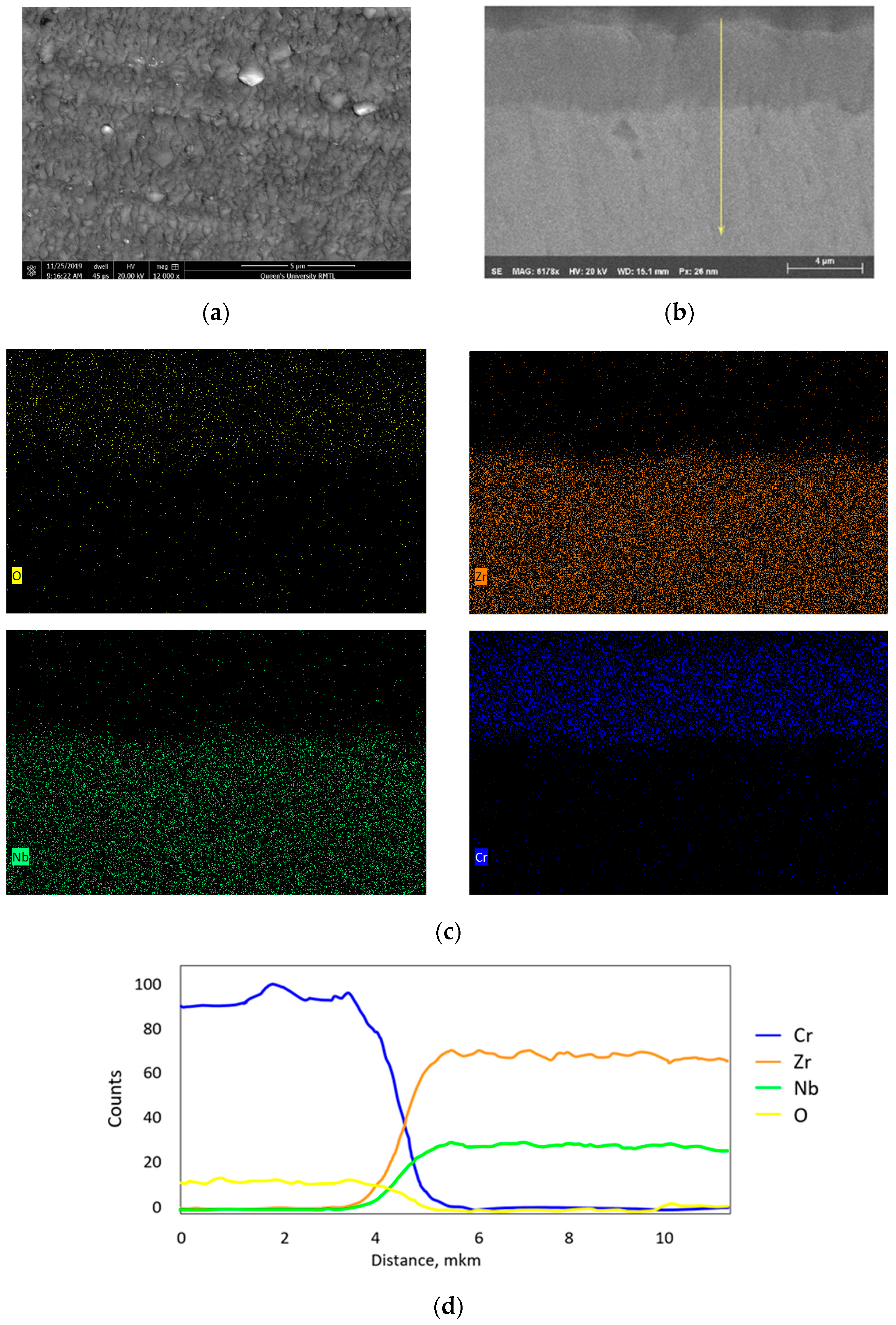
A scanning electron microscopy (SEM) picture of the as-deposited Cr coating on the Zr-2.5Nb substrate is shown in
Figure 3a. It can be seen that the Cr coating was uniformly deposited as a dense layer onto the Zr-2.5Nb substrate. The energy dispersive spectroscopy (EDS) results from the line scan shown in
Figure 3b illustrate that the Cr weight ratio accounted for the majority of the coating and the substrate had Zr and Nb as the main elements. The oxygen signal within the chromium layer (yellow line in
Figure 3b) was notable and uniform suggesting incorporation of oxygen during the coating process. According to the cross-sectional SEM micrographs and EDS analysis, the thickness of the as-deposited Cr coating on the Zr-2.5Nb substrate was about 5 μm.
3. Oxidation Experiments
The oxidation experiments were conducted in refreshed autoclaves in supercritical water at 500 °C to evaluate the corrosion behavior of the pressure tube specimen coated with metallic chromium (
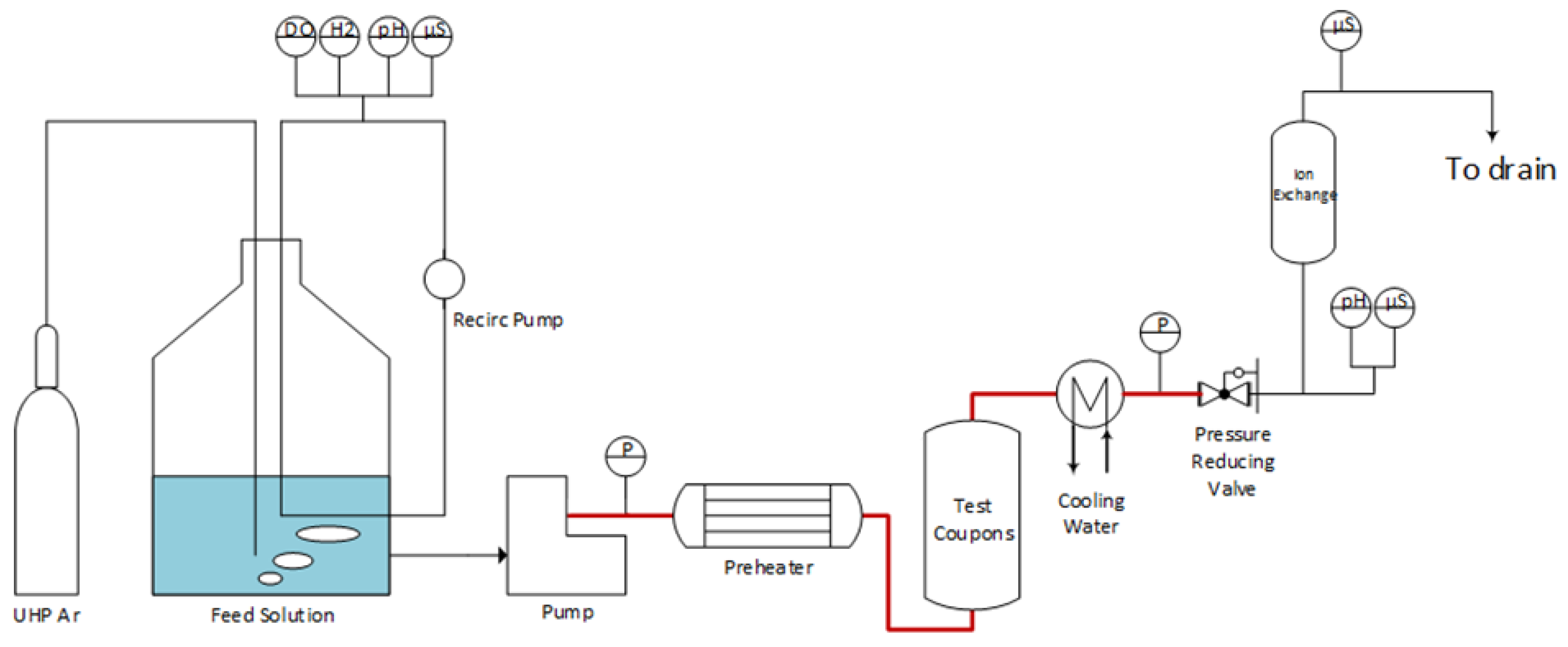
Table 1). Other coated specimens were tested at the same time and not reported here, including chromium-coated Zr-1Nb, Zr-1.2Cr-0.1Fe, and titanium coupons. The SCW-refreshed autoclave consisted of a 200 L Type 316 stainless-steel feed tank equipped with a gas bubbler for deoxygenating the feed water, a main loop pump (Vindum, syringe pump) delivering flow from 1 to 20 mL/min at pressures up to 25 MPa, an Inconel 625 electrical preheater (Carbolite-Gero Model: EVT Tube furnace), and a 1 L Inconel 625 autoclave (Parker Autoclave Engineers) rated for 25 MPa and 575 °C. Downstream of the autoclave was a cooler, back-pressure regulator (TESCOM, 4000 psi), and an ion exchange column (see
Figure 4).
Coupons were inserted on a sample tree composed of pre-oxidized 316 L stainless steel and exposed to the test solutions under the listed conditions in
Table 2. The pH (Endress Hauser Ceragel Model CPS71D), conductivity (Endress Hauser Condumax Model CLS21D), and dissolved oxygen concentration (Orbisphere Electrochemical Sensor model 31110.02) of the feed water were monitored, as were the pH and conductivity of the test solution exiting the autoclave.
The corrosion of in-core materials is strongly influenced by the effects of the oxidizing products of water radiolysis. When water is exposed to ionizing radiation, it decomposes to form chemically reactive species, such as •OH, H
2O
2, and O
2. These oxidizing species increase the corrosion susceptibility of the in-core materials, including the fuel cladding. Subramanian et al. [
12] estimated the concentrations of O
2 and H
2O
2 at 400 °C in the Canadian SCWR concept to be 0.3 mg/kg and 0.7 mg/kg, respectively. In the absence of measured values, these were used as the baseline for water chemistry. The solution in the feed tank was sparged with a mixture of oxygen and argon to obtain 0.63 mg/kg O
2.
After each exposure, the specimens removed from the autoclave were visually inspected. The specimens were rinsed with deionized water and dried in a stream of hot air until no mass change from water vaporization was observed. The specimens were then kept in a desiccator before being weighed and sent for further post-experimental analyses.
4. Post-Oxidation Analyses
Mass Changes of Oxidized Specimens
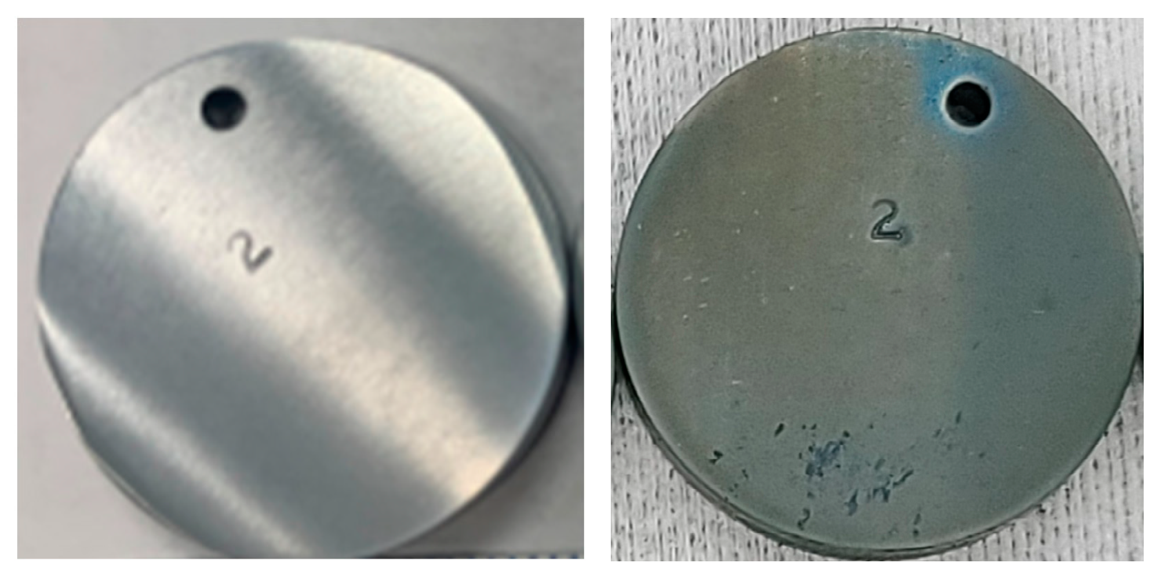
Before the test, the surfaces of the bare (uncoated) coupons were shiny and metallic, while the surfaces of the coated coupons were dull by comparison. After exposure to SCW, the surfaces of the coupons were dulled, with a cloudy appearance characteristic of an oxide film. No sign of spalling was observed on the exposed coupons (see
Figure 5).
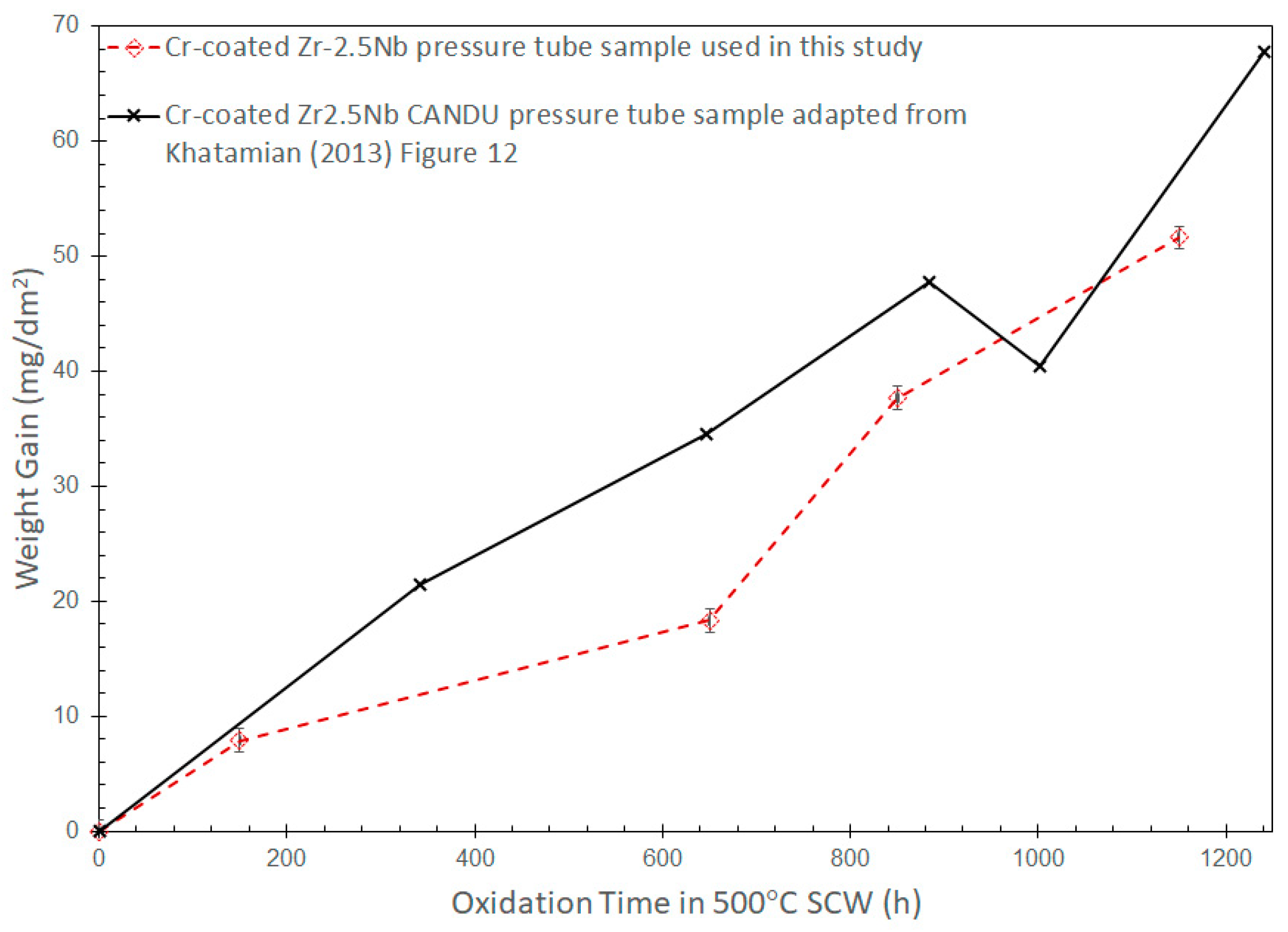
Figure 6 shows the autoclave oxidation results from Cr-coated Zr-2.5Nb tested at 500 °C and 24.5 Mpa containing 630 µg/kg O
2 in the feed water. The weight gain per unit area (in mg/dm
2) of each coupon was obtained by an analytical balance with an accuracy of ±0.001 mg for samples weighing less than 10 g, and the standard deviation between measurements of the same mass was 0.02 mg.
At the end of the 1150 h, the weight gain of the coated Zr-2.5Nb pressure tube coupon (dotted line) was about 50 mg/dm
2. To put this number into context, the as-received pressure tube was oxidized under similar SCW conditions, and the weight gain at the end of 48 h was about 89 mg/dm
2. A calculated penetration depth (the metal penetration indicating metal loss during oxidation can be calculated assuming that all oxidized metal atoms are retained on the surface as oxides:
, where
WG is the weight gain in mg/dm
2,
is the weight fraction of oxygen in oxide, and
is the density of the material in kg/m
3) of 4 µm was obtained from the 2-day exposure alone. In contrast, a metal penetration of only 1.5 µm after 1150 h was calculated for the chromium layer on the coated coupon, assuming that only chromium was oxidized and only Cr
2O
3 was formed. In the present SCW study, the Cr-coated Zr-2.5Nb showed improved corrosion resistance over the original Zr-2.5Nb pressure tube coupon, with a penetration depth of only 0.03 µm/d versus 2 µm/d, assuming linear oxidation kinetics. The design life of SCW-SMR fuel cladding is expected to be 5 years; therefore, the chromium layer may have to be 57 µm or thicker to endure. Long-term corrosion tests would be needed to confirm the assumed linear kinetics. A coating of such a thickness would have implications for the heat transfer and neutron economy of the fuel cladding, and would require further investigation. How oxides on corroded coated-Zr-2.5Nb coupons affect the heat transfer is demonstrated by thermal conductivity measurement in
Section 5. In addition to the change in the materials’ performances, the cost of the coating is also considered in
Section 6 via a cost model.
Previous experimental results on Cr-coated coupons exposed to 500 °C and 30 MPa of pure D
2O by Khatamian [
8] are included in the figure for comparison. In his experiments, Zr-2.5Nb was obtained from a 1 mm thick sheet supplied by ATI-Wah Chang, Albany. It was cold-rolled and annealed at 650 °C. It is important to note that a static autoclave was used by Khatamian. At a similar temperature, Cr-coated samples show similar weight gains. The weight gains differ within a factor of two at 650 h exposure; the weight gains of the coated specimen in the current study and the value obtained from Khatamian’s work are 18 and 35 mg/dm
2, respectively.
5. Effect of Coating on Heat Transfer
Although chromium coatings on zirconium alloy fuel cladding constitute only a fraction of the cladding thickness, they provide a barrier between the base cladding and coolant. Chromium coatings are expected to provide the following advantages over uncoated cladding: harder surface, minimum oxidation during normal operation, and improved high-temperature strength and steam oxidation kinetics [
13].
Recent research and development (R&D) of ATF (accident-tolerant fuel) focused on the application of Cr-coated zirconium alloy fuel cladding for current subcritical light-water reactors (LWRs). Lee et al. [
14] conducted flow boiling experiments to evaluate the heat transfer effects of Cr-coating on zirconium alloy fuel cladding. The tests were executed at atmospheric pressure. It was found that the heat transfer coefficients (HTCs) increased by 5.2% compared with a non-coated zircaloy-4 cladding. Cold-spray Cr coating increased the surface roughness of the fuel cladding, which allowed for generating smaller and faster bubbles; thus, the HTC improved.
Another study carried out by Su et al. [
15] analyzed the critical heat flux (CHF)—HF is a limiting heat flux at which the heated surface can no longer maintain continuous liquid contact—on chromium-coated zirconium alloy and bare zirconium alloy surfaces. The authors found that the chromium surface and the bare zirconium alloy surface had similar wettability and that there was practically no difference in the steady-state CHF limits, both under low-pressure and high-pressure conditions. The CHF limits were also similar when the chromium-coated surface was covered by 40 µm of CRUD (Chalk River Unidentified Deposit) deposit.
Although the observations presented by Su et al. are relevant for subcritical conditions, they are also important for accident scenarios in SCWRs, as these conditions are an extension of current LWRs, thus covering several phenomena and design-basis accidents (DBAs).
Furthermore, as SCWRs operate above the critical point of water (supercritical), the operating conditions are more demanding than those of current LWRs, with corrosion being one of the main concerns, especially on the fuel element cladding, potentially affecting the performance and safety of the reactor core design. Corrosion deposits on the cladding affect mainly two phenomena, namely hydraulic resistance and heat transfer, both impacting the thermalhydraulics design requirements. The surface roughness of the oxide layer directly affects the hydraulic resistance by enhancing the flow turbulence, in theory reducing the cladding temperature [
16]. However, if the oxide layer is thick enough, it could act as an insulator, thus changing the heat transfer characteristics of the fuel element, increasing the risk of overheating the cladding, and offsetting the benefits of the enhanced turbulence. This observation suggests that there is a threshold in the oxide layer thickness that needs to be identified. Currently, CNL is developing a model to predict the cladding temperature subjected to corrosion deposits and to estimate the threshold. However, to find this value, one of the most important transport variables needed is the thermal conductivity of this oxide layer. CNL conducted experiments to measure the thermal conductivity of the oxidized coupons.
Thermal Conductivity Measurements
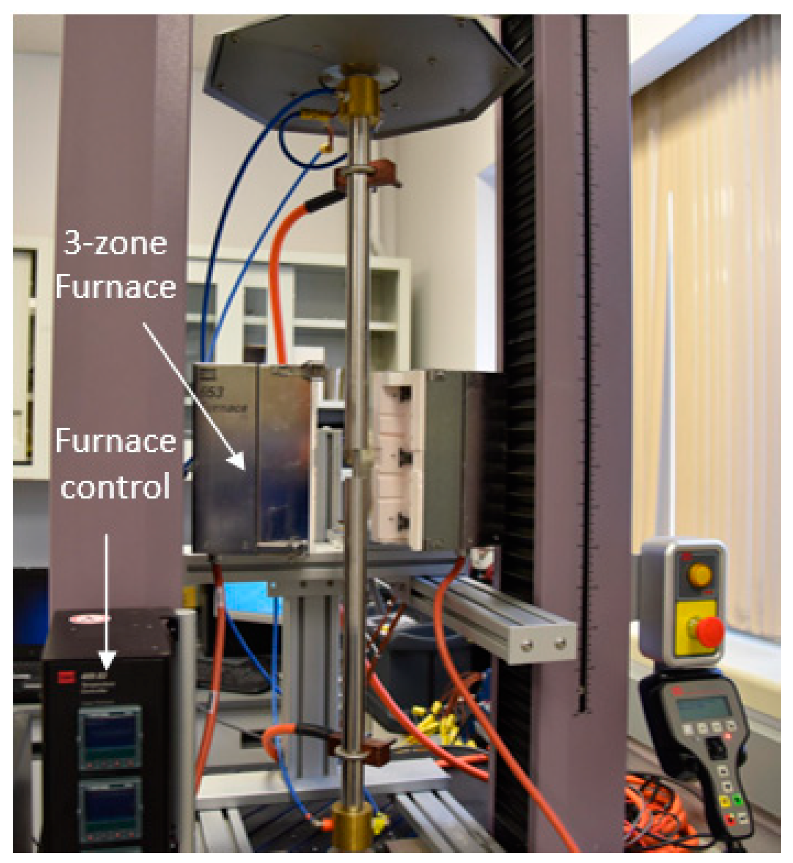
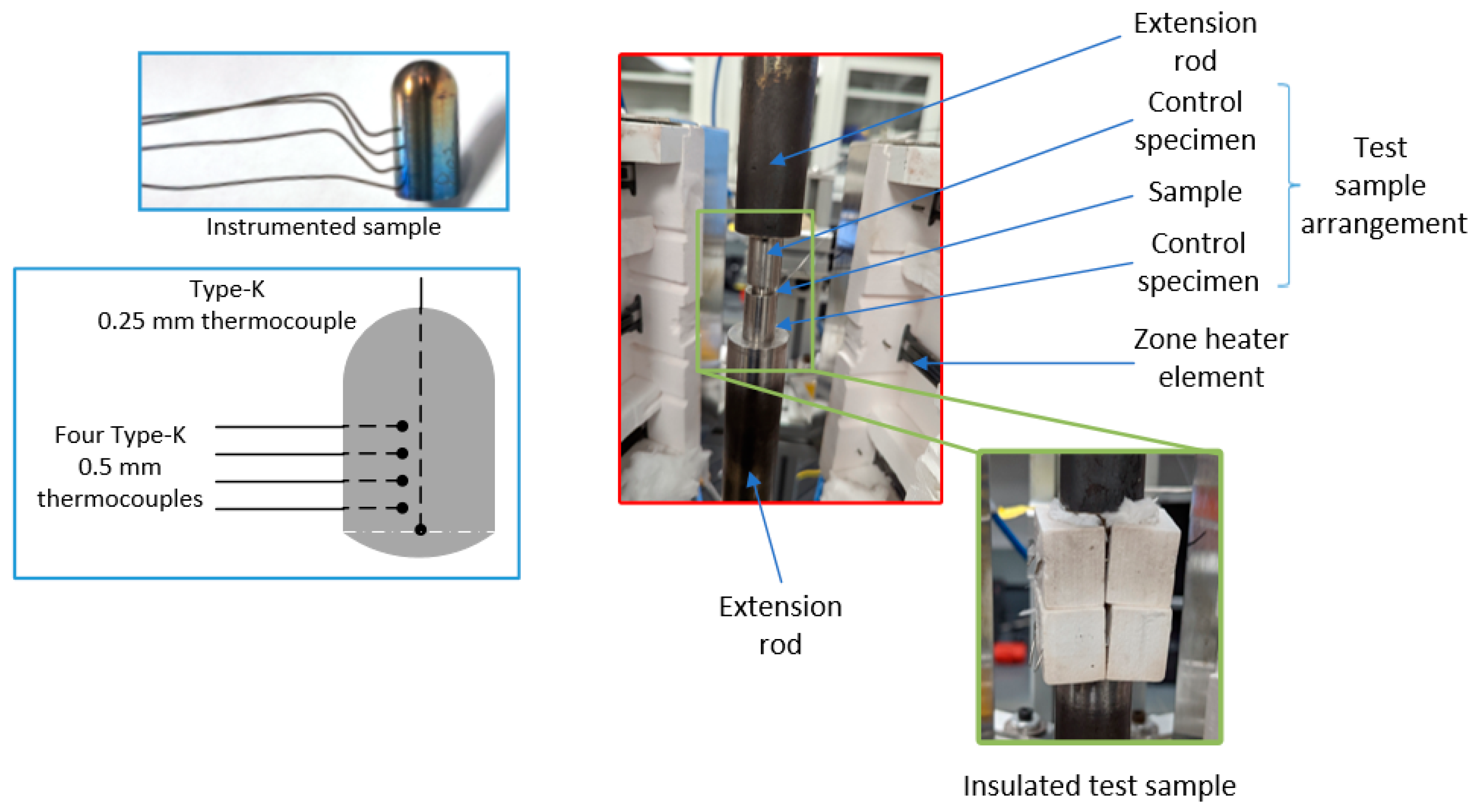
An apparatus was developed to measure the thermal conductivity of the coated samples, where the surface coating may be intentionally deposited on the sample to achieve a desired outcome or may be due to uncontrolled processes, such as oxidation. The thermal conductivity apparatus used for the present investigations adopted the Divided Bar methodology, with several modifications implemented to accommodate the nature of the specimen in the investigation. The apparatus is shown in
Figure 7 and the setup for the test sample is shown in
Figure 8. The apparatus consists of a 5 kN load bar connected to a furnace that has three independently heated zones capable of reaching 800 °C in each zone. The test sample arrangement comprises two control specimens, which have a known thermal conductivity, that sandwich the sample for which the thermal conductivity is being measured. The load is transferred to the test sample arrangement through extension rods to provide good contact at the interfaces between the three components of the test sample arrangement. The contact between the components is also further improved by using high-conductivity boron nitride paste at these interfaces. Using the three-zone furnace, a temperature gradient is imposed on the test sample arrangement. The three-zone furnace is also used to set a higher ambient environment, which reduces the heat loss from the test sample arrangement. The heat loss is further reduced by insulating the test sample arrangement with a porous 0.85 wt% alumina–silica composite (shown in
Figure 7) and wrapped in alumina wool to insulate the gaps for the thermocouple penetration. Each control specimen is instrumented with five thermocouples in series to measure the heat flow and capture the rate of radial heat loss from the insulated test sample arrangement. The thermocouples are spaced 3 mm apart.
To quantify the thermal conductivity of a coated sample, a benchmark test was performed with a polished sample (benchmark sample) that was not coated. The benchmark sample was made from Zr-2.5Nb material. The test was then repeated with the coated specimen (test sample). The thermal conductivity was obtained from steady-state data using the Fourier heat conduction equations across the test sample arrangement. Under steady-state conditions for a set of thermal resistances connected in series, the thermal conductivity for any given sample is given by:
where
k is the thermal conductivity,
A is the cross-sectional area, and
dT/dx is the temperature gradient along the heat conduction path. A significant portion of measurement uncertainty is incurred when estimating the interface conductance between the control specimen and the sample based on the measurements. To help reduce this uncertainty, the benchmark sample geometry is made to match the test sample geometry closely (±0.1 mm). The thickness of the as-deposited Cr coating on the Zr-2.5Nb substrate was about 5 μm. The overall sample diameter of the tested sample (Cr coating with 1150 h oxidation) was 12.20 mm and the overall sample thickness was 4.16 mm. The conductivities of the benchmark sample were measured as 16.61 and 16.69 W/(mK) ± 1.1 W/(mK) at 140 °C and 250 °C, respectively. The results of the measurements on a Zr-2.5Nb chromium-coated sample that was also oxidized for 1150 h is shown in
Table 3 below. The reported measurement uncertainty propagated from the measured temperatures and pressure through the root-sum-squared method. The measured thermal conductivities of the coated samples were lower than those of the bare samples. Thus, lower heat transfer rates or higher surface temperatures would be expected for conduction heat transfer. These conductivity values serve as an input to the overall heat transfer modeling, which would incorporate forced convection or two-phase heat transfer. The overall heat transfer modeling would capture potential heat transfer enhancements as a result of the porosity and increased roughness of the surface.
6. Cost Analysis of Coated Fuel Cladding
The coating selection for the oxidation experiments was based on the familiarity of chromium coating with the PVD method to conduct the initial R&D. Ongoing R&D will consider alternative coating processes, such as a future in-house VPS method. The differences in microstructure and surface uniformity between these coating methods could result in different oxidation behaviors. In addition, the neutron economy will have to be assessed. These performance indicators would need to be evaluated in relation to coating method aspects, such as commercial scalability and deposition time. Due to resource availability and future in-house development, a VPS method is chosen for initiating R&D coating economics for the SCW-SMR concept.
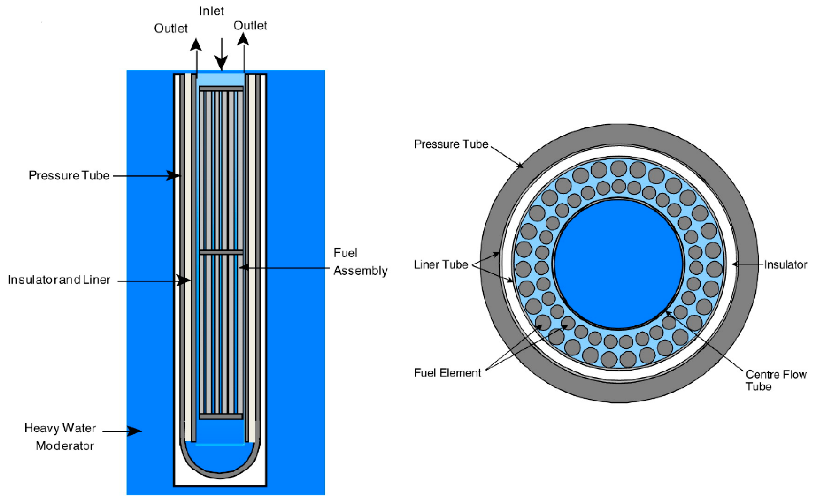
The VPS process is expected to be applied to coating the outer surface of a zirconium-based fuel cladding of a 64-element fuel bundle in an SCW-SMR, similar to that shown in
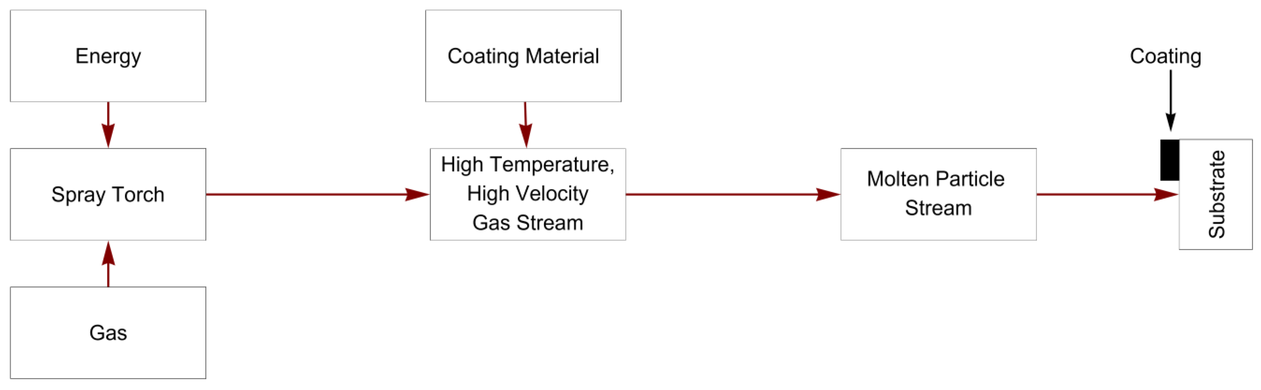
Figure 9. The VPS process, which is a direct current (DC) plasma spray process (
Figure 10), is also assumed to use a 99.99% purity Cr powder for evaluating the cost of coating.
A VPS process is useful for meeting SCW-SMR design requirements, because the VPS process “[p]revents in-flight and post-deposition oxidation of the spray powders insuring an oxide-free deposit” [
18]. The VPS process uses inert conditions (inert gases to generate the plasma) to avoid both an oxidizing atmosphere and a reducing atmosphere. An oxidizing atmosphere is avoided (no air or oxygen in the plasma gas) to prevent the oxidation of the coating and the cladding. A reducing atmosphere is avoided (no hydrogen in the plasma gas) to prevent the hydriding of the cladding (Zr absorbs hydrogen, which precipitates as hydrides, embrittling the material).
Figure 10.
Thermal Spray Concept Schematic. The red arrows indicate the flow of a thermal spray process, while the black arrow indicates the resulting product (i.e., the coating on the substrate). The schematic excludes cold spray and weld coating [
19].
Figure 10.
Thermal Spray Concept Schematic. The red arrows indicate the flow of a thermal spray process, while the black arrow indicates the resulting product (i.e., the coating on the substrate). The schematic excludes cold spray and weld coating [
19].
The estimated cost of coating fuel cladding is, therefore, based on a VPS process with chromium coating. Furthermore, as coating cost information is sometimes propriety, the costing approach presented below is intended to satisfy two aspects of the Generation IV International Forum’s (GIF) charter [
20]:
Research Emphasis: “The principal interest of GIF is in intermediate and long-term research”;
Open Research: “To the extent practicable, the R&D [research and development] fostered by the GIF should be open and nonproprietary”.
The costing approach is thus shown in a transparent manner to enable an understanding of the connection between reactor design requirements and coating options. The inherent uncertainty in the cost estimates should be recognized, as both the fuel concept and the coating options require further R&D.
6.1. Total Unit Cost of Coating
Two common methods of estimating the total unit cost of producing a coating are: (1) the cost to coat a specific part; and (2) the cost to spray a given amount of powder onto a substrate [
21,
22]. In either case, the total unit cost consists of two broad categories: the direct costs (
) and the indirect costs (
) [
18,
23]. More specifically, the total unit cost of producing a coating per part (
) in equation form is
where
is the operating hours per year and
is the number of hours per part [
18,
23]. In the second method, a generic cost function of the total cost per 1 kg of coating deposited (
) is shown in Equation (3)
where
is the cost of powder used per 1 kg of coating deposited,
is the cost of gas used for depositing 1 kg of material,
is the electricity cost per unit mass of coating,
is the labor cost per unit mass of coating, and
is the equipment cost allocated to the deposition of 1 kg of material [
22,
24,
25,
26,
27,
28]. In the present study, the second method is used, since less information is required [
22,
24,
25]. In addition, this aspect is important because the primary data source for estimating a vacuum plasma [
21] used both costing methods for providing cost estimates, but did not provide the methodology, nor the full assumptions or clarity on using some of the data provided.
The equations provided below for the main cost categories that make up the broad costs are guided by several references [
22,
24,
25,
26,
27,
28,
29,
30], which provide more details than those presented below. For instance, the maintenance costs and maintenance time are omitted. In addition, there are no adjustments for inflation from data sources. An economic factor not considered in this and other studies to determine the expected price of coating is profit; hence, studies focus on the unit cost. Despite these limitations, the equations for the main cost categories below may be used as “a basis for generating more exact cost figures” [
29]; hence, these equations provide a first approximation for calculating the order of magnitude of cost estimates.
Future experiments at CNL are expected to use a plasma spray process similar to the ultra-low-pressure plasma spray (ULPPS) system discussed in [
18,
31]. Potential changes to the cost estimates based on the equipment used from [
21] are, therefore, discussed.
6.1.1. Direct Cost
Since the spray material will be in powder form, the material costs are determined by the powder cost. This cost is determined by the amount of powder used or consumed (
) per 1 kg of deposited material and the powder price (
) [
22,
24,
25]
The material powder used is determined by
where
is the fractional overspray and
is the deposition efficiency [
22,
24,
25].
The total gas cost for depositing 1 kg of material (
) is the amount of gas (
) used to deposit 1 kg of material multiplied by the unit cost of gas (
) [
24,
25]
In addition, the amount of gas is determined by the gas flow rate (
) and the deposition time (
) in Equation (7) [
24,
25]
To account for a mixture of gases [
28], such as helium (
He) and argon (
Ar), Equations (6) and (7) are combined in Equation (8) and adjusted by mass fractions
where
is the mass fraction of
Ar used,
is the
Ar gas flow rate,
is the cost of
Ar (
$/kg),
is the mass fraction of He used,
is the
He gas flow rate, and
is the cost of
He (
$/kg).
Electricity is the only source of energy in the plasma process to generate the energy for the gas and creating the plasma. The cost of electricity depends on the power level (
) of the equipment, deposition time (
), and the electricity unit cost (
,
$/joule or
$/kWh) [
28]
Labor costs (
) depend on the number of workers (
), the time to complete the job (
), and the labor rate (
,
$/h), and [
22,
28]
6.1.2. Indirect Cost
Typically, indirect costs consist of various factors, such as maintenance workshop, quality control laboratory, and general administrative and expenses [
18,
23], but the most prominent component in coating cost studies is the amortization (
) of the capital investment in equipment acquisition (
). The formula for amortization depends on a fractional annual interest rate (
) and equipment lifetime (
) [
22,
26,
30]
An additional equation divides the
by the annual operating time (
) of the equipment and multiplies the time to run an operation to yield the equipment cost per 1 kg of coating deposited [
22,
24,
25]
6.1.3. Time
When applying the element of time to the main cost equations, it is useful to break down the model equipment run time (
) required to deposit 1 kg of coating deposit into the powder feed time (
—also referred to as the deposition or coating time) and idle time (
) [
22,
24,
25]
The time necessary to deposit a coating (
) is determined by dividing the powder used or consumed (
) per 1 kg of deposited material by the powder feed rate (
) [
22,
29,
30]
For the purposes of this study, no assumption is made for
, which is usually considered an independent variable. Hence, the costing in this study assumes
. In addition to incorporating the deposition (coating) time, the time to complete a job usually accounts for preparation and post-coating operations [
22,
26]. For the present study, however, the time to complete the job is assumed to be equal to the deposition time, i.e.,
.
In equation (12), the amortization cost was divided by the operating time of the equipment. This time period was calculated by [
21,
30]
6.1.4. Total Unit Cost
The equations of the coating cost model are used to calculate the total unit cost estimate for depositing 1 kg of coating based on the parameter values in
Table 4. Note that the currency in the tables and the cost analysis is expressed in American dollars.
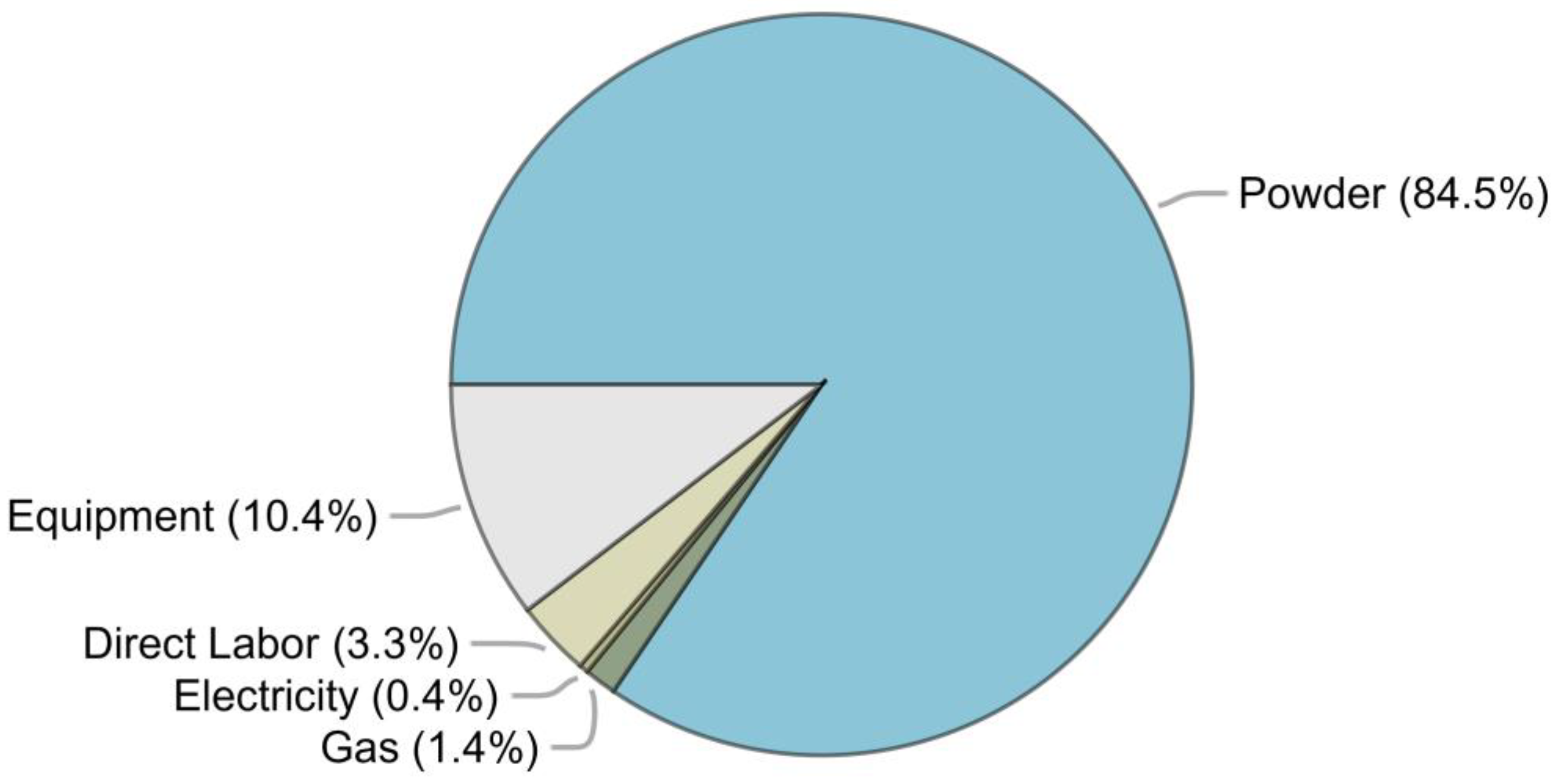
Table 5 presents the coating costs of using chromium in a VPS method for major cost categories and the total unit costs. The distribution of the major cost categories is presented in
Figure 11. The two largest costs are the powder cost and the amortization cost of the equipment.
Future experiments will likely use a plasma spraying process with specifications closer to those specified in a ULPPS process (
Table 6). The specifications in
Table 6 correspond to experiments based on reconstructing existing conventional low-pressure plasma spraying processes (LPPS, also termed VPS) [
31]. Regarding power costs, the ULPPS process is expected to yield a lower unit cost than the conventional VPS process. This benefit may be offset, since the powder feed rate for the ULPPS process is lower than that of the conventional VPS process. An additional increase in cost could stem from the increase in gas costs, since the gas flow rate used in the ULPPS is high [
18]. Despite the uncertainty in coating costs with a ULPPS process, the process is expected to produce superior coatings of greater density and adhesion [
37].
Alternative considerations are different powders and spray processes. While pure chromium has been studied for supercritical water environment conditions previously, the Ni-Cr alloy has also been studied under similar and sub-critical conditions [
38]. In light of the potentially different protection performances amongst the powder options, optimizing the plasma spray process and considering the different fuel residence times to minimize fuel cycle costs are recommended.
An alternative to the VPS process is a cold spray (CS) process. The CS process will likely increase the coating thickness to 50 μm [
35]—the VPS process can also achieve 50 µm thickness. This suggestion has been considered for accident-tolerant fuels in light-water reactors [
38,
39,
40]. A review of light-water reactor studies indicated that “because the coating layer is significantly thinner than the cladding, the neutronic performance should be close to that of the current UO
2–Zr system, with the exception of the neutron economy. The additional coating material in the cladding leads to greater neutron absorption by materials other than U, and the cycle length is reduced if the same type of fuel is used. Nevertheless, this issue can be easily resolved by slightly increasing the
235U enrichment” [
40]. For an SCW-SMR, however, the extent to which the thickness when using CS or the thickness when using either VPS or ULPPS would affect the neutron economy and its cost implications for an SCW-SMR are unknown.
Regardless of the potential changes in using chromium coating discussed thus far, an additional concern is the use of helium gas. Helium gas is typically considered scarce and has a relatively high price (could be as high as USD 100/kg) [
35], with the most recent helium shortage supply in 2022 [
41]. Alternatives to address the helium challenges are to consider alternative gases, such as nitrogen, as well as the technological option of recycling helium [
22,
26,
31,
35].
To complement the aforementioned topics, such as powder and gas selection, further analysis may consider the sensitivity of the total coating unit cost to powder and gas price changes, and the economic conditions that enable such changes.
6.2. Coating Cost of a Core
The cost of coating fuel cladding (
) all the fuel elements in the reactor core of a SCW-SMR was calculated using Equation (16)
where
is the coating depth,
is the coating surface area,
is the coating powder density, and
is the total unit cost of coating, as calculated above.
The parameters for the equation correspond to the required coating weight in a reactor core (
Table 7) based on the expected dimensions of a 64-element fuel bundle, and the chromium coating cost provided in the previous sub-section. Given these assumptions, the estimated cost is approximately USD 527,200 per reactor core.
7. Conclusions
The lessons learned during the development of the Canadian SCWR [
3] have been used for the development of the Canadian SCW-SMR concept. Of utmost importance is the early identification of key variables, design targets, requirements, and constraints, and their interrelations. The identification of these parameters requires multiple models to draw the interrelations. For that reason, a methodological and systematic approach is used. In this approach, three groups of requirements are used to classify and identify the parameters, including: (1) performance, (2) safety, and (3) economics [
5].
This study described and compared the results of corrosion tests. In order to reduce the corrosion rate of zirconium fuel cladding under SCW-SMR conditions, Cr-coated Zr-2.5Nb pressure tube was proposed and tested under relevant conditions for approximately 48 days. The effectiveness of the coating in reducing the corrosion of a standard Zr-2.5Nb pressure tube was demonstrated. Weight gain was used for assessing the performance of the coupon, which had some inherent uncertainties, but was useful as a first approximation. The corrosion performance of the Cr-coated Zr-2.5Nb pressure tube sample was consistent with that in previous work under 500 °C and 25 MPa oxygenated SCW, the conditions relevant to the Canadian SCW-SMR. When the life of the SCW-SMR of fuel cladding is expected to last 5 years, a thicker chromium coating might be considered to substantially the reduce corrosion rate of the zirconium fuel cladding. A thicker coating, however, could potentially affect the heat transfer and neutron economy of the fuel cladding. Further study on these two fronts is required.
This study also presented a limited review of the important safety aspects of chromium-coated zirconium alloy claddings, such as the potential impact on heat transfer due to an increase in oxide thickness and the corresponding reduction in thermal conductivity. This information is needed for a more realistic estimation of the peak cladding, fuel temperatures, and maximum oxide layer thickness. CNL is working on a heat transfer model to estimate the temperature profiles of oxidized claddings. However, the model requires the thermal conductivity of the oxide layer. To close this gap, thermal conductivity measurements of the exposed coupon were conducted and the results are presented in
Table 3.
Finally, a cost model for coating in a vacuum spray process was applied to estimate and analyze the chromium coating costs of fuel cladding. The estimated total cost of coating fuel cladding with chromium is approximately USD 527,200 per reactor core. The cost analysis indicated that chromium powder was the major cost item determining the total cost when compared with equipment, labor, electricity, and gas costs. The coating cost method and estimates are expected to be used for further analysis when considering alternative fuel bundle options.
Author Contributions
The authors contributed to the conceptualization, writing, analysis, methodology, investigation and visualization of the different sections of the manuscript as follows. Abstract, introduction, and conclusion sections, K.K.-A., A.N.-D. and A.M.; materials and methods, oxidation experiments, and post-oxidation analyses sections, K.K.-A.; effect of coating on heat transfer section, A.N.-D. and H.Z.; thermal conductivity measurements section, C.A.; cost analysis of coated fuel cladding section, A.M. All authors have read and agreed to the published version of the manuscript.
Funding
This study was funded by Atomic Energy of Canada Limited under the auspices of the Federal Nuclear Science and Technology Program. The research was conducted at the Canadian Nuclear Laboratories.
Institutional Review Board Statement
Not applicable.
Informed Consent Statement
Not applicable.
Data Availability Statement
Not applicable.
Acknowledgments
The authors are grateful for the support of M. Edwards, H. Namburi, B. Haley, A. Turcotte, S. Luk, E. Hachey, D. Nauss, P. Sanongboon, G. Cota-Sanchez, V. Branco, L. Walters, and A. Siddiqui. The authors are also grateful to the editors and the anonymous reviewers for their reviews, comments, and suggestions.
Conflicts of Interest
The authors declare no conflict of interest. The funders had no role in the design of the study; in the collection, analyses, or interpretation of data; in the writing of the manuscript; or in the decision to publish the results.
References
- International Atomic Energy Agency (IAEA). Advances in Small Modular Reactor Technology Developments: A Supplement to IAEA Advanced Reactors Information System (ARIS); IAEA: Vienna, Austria, 2020; Available online: https://aris.iaea.org/Publications/SMR_Book_2020.pdf (accessed on 21 July 2023).
- OECD Nuclear Energy Agency. Technology Roadmap Update for Generation IV Nuclear Energy Systems; Generation IV International Forum: Paris, France, 2014; Available online: https://www.gen-4.org/gif/upload/docs/application/pdf/2014-03/gif-tru2014.pdf (accessed on 21 July 2023).
- Yetisir, M.; Xu, R.; Gaudet, M.; Movassat, M.; Hamilton, H.; Nimrouzi, M.; Goldak, J. Various Design Aspects of the Canadian Supercritical Water-Cooled Reactor Core. ASME J. Nucl. Eng. Radiat. Sci. 2015, 2, 011007. [Google Scholar] [CrossRef]
- A Call to Action: A Canadian Roadmap for Small Modular Reactors. Available online: https://smrroadmap.ca/ (accessed on 28 March 2023).
- Fenech, H. (Ed.) Heat Transfer and Fluid Flow in Nuclear Systems; Pergamon Press: New York, NY, USA, 1981. [Google Scholar]
- Khumsa-Ang, K.; Rousseau, S.; Shiman, O. Weight Gain and Hydrogen Absorption in Supercritical Water at 500 °C of Chromium-Coated Zirconium-Based Alloys: Transverse Versus Longitudinal Direction. ASME J. Nucl. Eng. Radiat. Sci. 2022, 8, 031102. [Google Scholar] [CrossRef]
- Motta, A.T.; Couet, A.; Comstock, R.J. Corrosion of zirconium alloys used for nuclear fuel cladding. Annu. Rev. Mater. Res. 2015, 45, 311–343. [Google Scholar] [CrossRef]
- Khatamian, D. Corrosion and deuterium uptake of Zr-based alloys in supercritical water. J. Supercrit. Fluids 2013, 78, 132–142. [Google Scholar] [CrossRef]
- Motta, A.T.; Yilmazbayhan, A.; Gomes da Silva, M.J.; Comstock, R.J.; Was, G.S.; Busby, J.T.; Gartner, E.; Peng, Q.; Jeong, Y.H.; Park, J.Y. Zirconium alloys for supercritical water reactor applications: Challenges and possibilities. J. Nucl. Mater. 2007, 371, 61–75. [Google Scholar] [CrossRef]
- Peng, Q.; Gartner, E.; Busby, J.T.; Motta, A.T.; Was, G.S. Corrosion behavior of model zirconium alloys in deaerated supercritical water at 500 °C. Corrosion 2007, 63, 577–590. [Google Scholar] [CrossRef]
- Kaneda, J.; Kasahara, S.; Kuniya, J.; Kano, F.; Takahashi, H.; Matsui, H. Material properties of stainless steels modified with addition of zirconium for supercritical water-cooled reactor. In Proceedings of the ICAPP 2007—International Congress on Advances in Nuclear Power Plants: The Nuclear Renaissance at Work, Nice, France, 13–18 May 2007. Paper No. 7500. [Google Scholar]
- Subramanian, V.; Joseph, J.M.; Subramanian, H.; Noël, J.J.; Guzonas, D.A.; Wren, J.C. Steady-State Radiolysis of Supercritical Water: Model Predictions and Validation. ASME J. Nucl. Eng. Radiat. Sci. 2016, 2, 021021. [Google Scholar] [CrossRef]
- United States Nuclear Regulatory Commission. Supplemental Guidance Regarding the Chromium-Coated Zirconium Alloy Fuel Cladding Accident Tolerant Fuel Concept; ATF-ISG-2020-01; United States Nuclear Regulatory Commission: Rockville, MD, USA, 2020. Available online: https://www.nrc.gov/docs/ML1934/ML19343A121.pdf (accessed on 21 July 2023).
- Lee, D.; Elward, B.; Brooks, P.; Umretiya, R.; Rojas, J.; Bucci, M.; Rebak, R.B.; Anderson, M. Enhanced flow boiling heat transfer on chromium coated zircaloy-4 using cold spray technique for accident tolerant fuel (ATF) materials. Appl. Therm. Eng. 2021, 185, 116347. [Google Scholar] [CrossRef]
- Su, G.Y.; Moreira, T.A.; Lee, D.; Jena, A.; Wang, G.; Byers, A.; Phillips, B.; Karoutas, Z.; Anderson, M.; Bucci, M. Wettability and CHF limits of Accident-Tolerant nuclear fuel cladding materials in light water reactor conditions. Appl. Therm. Eng. 2022, 216, 119018. [Google Scholar] [CrossRef]
- Chen, J.; Yang, S.G.; Zhao, R.; Cheng, W.L. Experimental study on the effect of wall roughness on heat transfer characteristics of supercritical carbon dioxide in vertical tubes. Int. J. Heat Mass Transf. 2022, 196, 123258. [Google Scholar] [CrossRef]
- Nava Domínguez, A.; Onder, N.; Rao, Y.; Leung, L. Evolution of the Canadian SCWR Fuel-Assembly Concept and Assessment of the 64 Element Assembly for Thermalhydraulic Performance. CNL Nucl. Rev. 2016, 5, 221–238. [Google Scholar] [CrossRef]
- Boulos, M.I.; Fauchais, P.L.; Heberlein, J.V.R. Thermal Spray Fundamentals; Springer: Cham, Switzerland, 2021. [Google Scholar]
- Fauchais, P.L.; Heberlein, J.V.R.; Boulos, M.I. Thermal Spray Fundamentals; Springer: New York, NY, USA, 2014. [Google Scholar]
- Generation IV International Forum (GIF). Charter of the Generation IV International Forum; GIF: Paris, France, 2006. [Google Scholar]
- Meyer, P.; Rusch, W. Production Coating Cost Comparison. In Proceedings of the Thermal Spray 2003: Proceedings from the International Thermal Spray Conference, Orlando, FL, USA, 5–8 May 2003; Marple, B.R., Moreau, C., Eds.; ASM International: Almere, The Netherlands, 2003; pp. 123–128. [Google Scholar]
- Helfritch, D.; Stier, O.; Villafuerte, J. Cold Spray Economics. In Modern Cold Spray; Villafuerte, J., Ed.; Springer: Cham, Switzerland, 2015; pp. 377–401. [Google Scholar]
- Boulos, M.I.; Fauchais, P.L.; Henne, R.H.; Pfender, E. Plasma in the Thermal Spray Coating Industry. In Handbook of Thermal Plasmas; Springer: Cham, Switzerland, 2022; pp. 1–87. [Google Scholar]
- Stier, O. Cost Analysis of Cold Sprayed MCrAlY Coatings for Gas Turbine Blades. In Proceedings of the Kolloquium Hochgeschwindigkeits-Flammspritzen/HVOF Spraying, Erding, Germany, 8–9 November 2012; Penszior, C., Heinrich, P., Eds.; Gemeinschaft Thermisches Spritzen e.V. (Association of Thermal Sprayers): Unterschleißheim, Germany, 2012; pp. 171–184. [Google Scholar]
- Stier, O. Fundamental Cost Analysis of Cold Spray. J. Therm. Spray Technol. 2014, 23, 131–139. [Google Scholar] [CrossRef]
- Nardi, A.; Helfritch, D.; Eden, T.; Ozdemir, O.C. Cold Spray Economics. In Practical Cold Spray; Champagne, V.K., Ozdemir, O.C., Nardi, A., Eds.; Springer: Cham, Switzerland, 2021; pp. 285–310. [Google Scholar]
- Elzey, D.M.; Wadley, H.N.G. Cost Models for MMC Manufacturing Processes; National Aeronautics and Space Administration: Washington, DC, USA, 1996.
- MacDonald, D.; Rahmati, S.; Jodoin, B.; Birtch, W. An Economical Approach to Cold Gas Dynamic Spraying Using In-Line Nitrogen-Helium Blending. In Proceedings of the ITSC2018. Thermal Spray 2018: Proceedings from the International Thermal Spray Conference, Orlando, FL, USA, 7–10 May 2018; Azarmi, F., Balani, K., Li, H., Eden, T., Shinoda, K., Hussain, T., Toma, F.-L., Lau, Y.-C., Veilleux, J., Eds.; ASM International: Almere, The Netherlands, 2018; pp. 675–682. [Google Scholar]
- American Welding Society (AWS) Committee on Thermal Spraying. Thermal Spraying: Practice, Theory, and Application; American Welding Society: Doral, FL, USA, 1985. [Google Scholar]
- De Botton, O. An Economic and Engineering Assessment of Plasma-Sprayed Ceramic Coatings. Master’s Thesis, Massachusetts Institute of Technology, Cambridge, MA, USA, 1988. Available online: https://hdl.handle.net/1721.1/148162 (accessed on 22 February 2023).
- Mauer, G. Plasma Characteristics and Plasma-Feedstock Interaction Under PS-PVD Process Conditions. Plasma Chem. Plasma Process. 2014, 34, 1171–1186. [Google Scholar] [CrossRef]
- Alfa Aesar 10148 Chromium Powder, -325 Mesh, 99% (Metals Basis). Available online: https://www.alfa.com/en/catalog/010148/ (accessed on 31 March 2023).
- Air Products Weight and Volume Equivalents. Available online: https://www.airproducts.com/gases/gas-facts (accessed on 31 March 2023).
- Becker, L. Chemical Elements by Market Price. Available online: http://www.leonland.de/elements_by_price/en/list (accessed on 15 April 2023).
- Stier, O. (Siemens AG, Berlin, Germany). Personal communication, 2023. [Google Scholar]
- European Central Bank US Dollar (USD). Available online: https://www.ecb.europa.eu/stats/policy_and_exchange_rates/euro_reference_exchange_rates/html/eurofxref-graph-usd.en.html (accessed on 31 March 2023).
- Mauer, G.; Vaßen, R.; Stöver, D. Thin and Dense Ceramic Coatings by Plasma Spraying at Very Low Pressure. J. Therm. Spray Technol. 2010, 19, 495–501. [Google Scholar] [CrossRef]
- Yang, J.; Steinbrück, M.; Tang, C.; Große, M.; Liu, J.; Zhang, J.; Yun, D.; Wang, S. Review on Chromium Coated Zirconium Alloy Accident Tolerant Fuel Cladding. J. Alloys Compd. 2022, 895, 162450. [Google Scholar] [CrossRef]
- Ševeček, M.; Gurgen, A.; Seshadri, A.; Che, Y.; Wagih, M.; Phillips, B.; Champagne, V.; Shirvan, K. Development of Cr Cold Spray–Coated Fuel Cladding with Enhanced Accident Tolerance. Nucl. Eng. Technol. 2018, 50, 229–236. [Google Scholar] [CrossRef]
- Chen, S.-L.; He, X.-J.; Yuan, C.-X. Recent Studies on Potential Accident-Tolerant Fuel-Cladding Systems in Light Water Reactors. Nucl. Sci. Tech. 2020, 31, 32. [Google Scholar] [CrossRef]
- Kramer, D. Helium Is Again in Short Supply. Phys. Today 2022. [Google Scholar] [CrossRef]
- Melting, Boiling, Triple, and Critical Point Temperatures and Densities of the Elements. In CRC Handbook of Chemistry and Physics; Rumble, J.R. (Ed.) CRC Press: Boca Raton, FL, USA, 2022. [Google Scholar]
| Disclaimer/Publisher’s Note: The statements, opinions and data contained in all publications are solely those of the individual author(s) and contributor(s) and not of MDPI and/or the editor(s). MDPI and/or the editor(s) disclaim responsibility for any injury to people or property resulting from any ideas, methods, instructions or products referred to in the content. |
© 2023 by the authors. Licensee MDPI, Basel, Switzerland. This article is an open access article distributed under the terms and conditions of the Creative Commons Attribution (CC BY) license (https://creativecommons.org/licenses/by/4.0/).


