Article

On the Thermally Induced Interfacial Behavior of Thin Two-Dimensional Hexagonal Quasicrystal Films with an Adhesive Layer

1
School of Mechanics and Safety Engineering, Zhengzhou University, Zhengzhou 450001, China
2
School of Civil and Mechanical Engineering, Curtin University, Perth, WA 6845, Australia
3
School of Mechanical and Power Engineering, Zhengzhou University, Zhengzhou 450001, China
*
Author to whom correspondence should be addressed.
Submission received: 17 February 2024 / Revised: 8 March 2024 / Accepted: 15 March 2024 / Published: 16 March 2024
(This article belongs to the Special Issue Analysis of Structure and Mechanical Properties of Coatings)

Abstract

:
The mechanical response of a quasicrystal thin film is strongly affected by an adhesive layer along the interface. In this paper, a theoretical model is proposed to study a thin two-dimensional hexagonal quasicrystal film attached to a half-plane substrate with an adhesive layer, which undergoes a thermally induced deformation. A perfect non-slipping contact condition is assumed at the interface by adopting the membrane assumption. An analytical solution to the problem is obtained by constructing governing integral–differential equations for both single and multiple films in terms of interfacial shear stresses that are reduced to a linear algebraic system via the series expansion of Chebyshev polynomials. The solution is compared to that without adhesive layers, and the effects of the aspect ratio of films, material mismatch, and the adhesive layer, as well as the interaction between films, are discussed in detail. It is found that the adhesive layer can soften the localized stress concentration. This study is instructive to the accurate safety assessment and functional design of a quasicrystal film system.

1. Introduction

Quasicrystal (QC) solids with specially arranged atoms perform a lot of unique properties, such as low surface energy, ideal wear and corrosion resistance, and high hardness [1,2,3]. With these extraordinary properties, QCs have great potential in surface-modified coatings and functional films [4,5,6,7,8]. In addition, QC optical films hold significant promise and application value. Compared with traditional photonic crystal films, they exhibit richer photonic bandgaps, independence of the incident direction, and lower refractive index thresholds [9,10]. Some QC optical films were designed and produced in the laboratory [11,12]. Thus, QC materials, as a new kind of structural materials, have broad engineering application prospects.
Much research was conducted on the preparation technology of QC films [13,14]. During production and service, thermal stress is unavoidable, which is a main source of residual stress in thin films. Generally, thermal stress appears when the thermal expansion coefficients are different between the film and substrate [15]. The residual stress may cause the cracking or debonding of film and lead to damage or even failure [15,16,17]. Therefore, a good understanding of the mechanical response under thermally induced deformation can largely improve and optimize the production and performance of the QC film system.
There are usually two typical theoretical models for analyzing the interfacial behavior in film/substrate systems. One is the crack model, and the other is the contact model. The crack model was developed by Akisanya and Fleck [18] and Yu et al. [19], which assumes a pre-existing line crack located at the edge of a thin film. However, in engineering applications, the film is usually tightly bonded to the substrate. Therefore, the contact model was proposed. In this model, the contact mechanics theory is adopted to analyze the stress field along the interface and the singularity at the edge of the film and then to predict potential cracking [20]. For example, Arutiunian [21] investigated the perfect contact problem between a finite-length reinforced material and a half-plane and obtained the solution in terms of an infinite power series. Later on, Erdogan and Gupta [22] solved the problem more effectively by constructing the integral equations in terms of interfacial shear stress. Meanwhile, Hu [23] analyzed interfacial stresses with dielectric and conducting layers of thin films via the finite difference method. Later, Shield and Kim [24] considered the bending stiffness and proposed a beam model to study a film/substrate system. The thermally induced deformation in film systems was discussed in detail by Lanzoni and Radi [15]. Chen et al. [25,26] extended the model to functionally graded substrates and discussed the influence of a material inhomogeneity parameter. More smart material films were studied, such as thermoelectric films [27] and lithium-ion films [28]. Several mechanical models were developed for the three-dimensional analysis [29] and double-film case [30]. Furthermore, when applied in MEMS or electrostatically actuated micropumps, the size of films can reach a micro- or even nanoscale, and thus, the theoretical model was developed to consider the size effect [31,32,33].
In engineering applications, the film is usually bonded to the substrate with an adhesive layer. The layer can not only bond film and substrate together, but it can also alter the mechanical response of the whole structure. Qing [34] studied the influence of an adhesive layer on the performance of a piezoelectric film bonded to a substrate and revealed that the increase in adhesive thickness would alter the resonant frequency and electromechanical impedance, as well as the amplitude of signals. The durability and regulating effect of adhesive layers on film systems were explored comprehensively [35,36,37,38]. Thus, it is essential to fully understand the mechanical response of a QC film system with adhesive layers. A few studies were conducted on QC films without adhesive layers [39,40]; however, to the best of our knowledge, there is no research on QC films with an adhesive layer. Up to now, a few hundred solid QC materials have been found, among which over one-third belong to two-dimensional (2D) QCs. Therefore, we select the 2D hexagonal QC as a film material and study its mechanical behavior with an adhesive layer.
This paper is organized as follows. In Section 2, the problem is first described and each part of the system is analyzed correspondingly. Then, Section 3 presents the interfacial boundary conditions and constructs the governing integral–differential equations in terms of interfacial shear stresses. Next, the model is developed into a double film case in Section 4. After that, Section 5 discusses the effects of various influencing factors in more detail. Finally, some important conclusions are drawn in Section 6.

2. Formulation of the Problem

Consider a thin 2D hexagonal QC film bonded on an isotropic elastic substrate, including an adhesive layer. The lengths of the QC film and adhesive layer are both l = 2 a , and the thicknesses of the QC film and adhesive layer are, respectively, denoted as h f and h l . Compared with the thin QC film and adhesive layer, crystal substrate can be regarded as semi-infinite. As illustrated in Figure 1, the rectangular coordinate system (xoz) is selected with an x-axis along the interface while the z-axis is perpendicular to the interface; meanwhile, the origin point is located at the center of the adhesive layer.

2.1. The QC Film

For a 2D hexagonal QC material with thermal effect referred to a rectangular coordinates system x ,   y ,   z , it is assumed that the plane oxy is parallel to the quasiperiodic plane, and the orthogonal direction oz is the periodic direction. For 2D hexagonal QCs, the point groups 6 mm, 622, 6 m2, and 6/mmm belong to Laue class 10. The linear constitutive equations take the following forms [41]
σ x x = c 11 𝜕 u x 𝜕 x + c 12 𝜕 u y 𝜕 y + c 13 𝜕 u z 𝜕 z + R 1 𝜕 w x 𝜕 x + R 2 𝜕 w y 𝜕 y β 1 θ , σ y y = c 12 𝜕 u x 𝜕 x + c 11 𝜕 u y 𝜕 y + c 13 𝜕 u z 𝜕 z + R 2 𝜕 w x 𝜕 x + R 1 𝜕 w y 𝜕 y β 1 θ , σ z z = c 13 𝜕 u x 𝜕 x + c 13 𝜕 u y 𝜕 y + c 33 𝜕 u z 𝜕 z + R 3 𝜕 w x 𝜕 x + R 3 𝜕 w y 𝜕 y β 3 θ , σ x z = c 44 𝜕 u x 𝜕 z + 𝜕 u z 𝜕 x + R 4 𝜕 w x 𝜕 z ,   σ y z = c 44 𝜕 u y 𝜕 z + 𝜕 u z 𝜕 y + R 4 𝜕 w y 𝜕 z , σ x y = c 66 𝜕 u y 𝜕 x + 𝜕 u x 𝜕 y + R 6 𝜕 w x 𝜕 y + R 6 𝜕 w y 𝜕 x , H x x = R 1 𝜕 u x 𝜕 x + R 2 𝜕 u y 𝜕 y + R 3 𝜕 u z 𝜕 z + K 1 𝜕 w x 𝜕 x + K 2 𝜕 w y 𝜕 y , H y y = R 2 𝜕 u x 𝜕 x + R 1 𝜕 u y 𝜕 y + R 3 𝜕 u z 𝜕 z + K 2 𝜕 w x 𝜕 x + K 1 𝜕 w y 𝜕 y ,   H x z = R 4 𝜕 u x 𝜕 z + 𝜕 u z 𝜕 x + K 4 𝜕 w x 𝜕 z , H y z = R 4 𝜕 u y 𝜕 z + 𝜕 u z 𝜕 y + K 4 𝜕 w y 𝜕 z , H x y = R 6 𝜕 u y 𝜕 x + 𝜕 u x 𝜕 y + K 3 𝜕 w x 𝜕 y + K 6 𝜕 w y 𝜕 x ,   H y x = R 6 𝜕 u y 𝜕 x + 𝜕 u x 𝜕 y + K 6 𝜕 w x 𝜕 y + K 3 𝜕 w y 𝜕 x , q x = k 11 𝜕 θ 𝜕 x ,   q y = k 11 𝜕 θ 𝜕 y ,   q z = k 33 𝜕 θ 𝜕 z ,
where w i and u i are phason and phonon displacements; H i j and σ i j are phason and phonon stresses; c i j K i , R i , and β i are, respectively, elastic stiffness constants, phonon–phason elastic constants, and thermal constants; θ and q i denote the temperature change and heat fluxes, respectively, with θ = 0 corresponding to a reference state. As the problem is on the xoz plane, all the components should be independent of the spatial variable y. Thus, Equation (1) can be reduced to
σ x x = c 11 𝜕 u x 𝜕 x + c 13 𝜕 u z 𝜕 z + R 1 𝜕 w x 𝜕 x β 1 θ , σ z z = c 13 𝜕 u x 𝜕 x + c 33 𝜕 u z 𝜕 z + R 3 𝜕 w x 𝜕 x β 3 θ , σ x z = c 44 𝜕 u x 𝜕 z + 𝜕 u z 𝜕 x + R 4 𝜕 w x 𝜕 z , H x x = R 1 𝜕 u x 𝜕 x + R 3 𝜕 u z 𝜕 z + K 1 𝜕 w x 𝜕 x , H x z = R 4 𝜕 u x 𝜕 z + 𝜕 u z 𝜕 x + K 4 𝜕 w x 𝜕 z , q x = k 11 𝜕 θ 𝜕 x ,   q z = k 33 𝜕 θ 𝜕 z ,
with their governing equations without body forces and heat sources as
𝜕 σ x x 𝜕 x + 𝜕 σ z x 𝜕 z = 0 ,   𝜕 σ z x 𝜕 x + 𝜕 σ z z 𝜕 z = 0 ,   𝜕 H x x 𝜕 x + 𝜕 H x z 𝜕 z = 0 ,   𝜕 q x 𝜕 x + 𝜕 q z 𝜕 z = 0 .
As the 2D hexagonal QC film is significantly thin, it is reasonable to ignore the peeling stress and adopt a membrane assumption in the present work, which means only the interfacial shear stress transfers across the interface [15]. In addition, it is well known that thermal expansion basically results in axial deformation. Based on the characteristics of 2D hexagonal QCs and the film/substrate mechanical model, we propose the following assumptions: (1) σ x x f and u x f are uniformly distributed along the thickness of 2D hexagonal QC film, and they are only dependent on spatial variable x; (2) phason stresses equal to zero at the interface, and they cannot transfer between QC materials and crystal materials [42], thus only phonon interfacial shear stress τ x transfers between the 2D hexagonal QC film and adhesive layer; (3) phonon and phason stresses σ z z f and H x x f can be neglected in the QC film, where the superscript “ f ” denotes the 2D hexagonal QC film.
According to these assumptions, the equilibrium condition in Equation (3) can be rewritten as
𝜕 σ x x f 𝜕 x + τ x h f = 0 .
The tractions are free at two ends of QC film, that is
σ x x f x = ± a = 0 .
As all the loads are transferred through the interface and they are caused by interfacial shear stress τ , combining Equations (4) and (5) leads to the normal stress σ x x f in the 2D hexagonal QC film in terms of τ x as
σ x x f x = a x τ ξ h f d ξ ,
with
a a τ ξ d ξ = 0 .
Adopting assumption (3), σ z z f = 0 , and H x x f = 0 , and combining with Equation (2) yields
𝜕 u z 𝜕 z = R 1 R 3 c 13 K 1 c 33 K 1 R 3 2 𝜕 u x 𝜕 x + K 1 β 3 c 33 K 1 R 3 2 θ ,
𝜕 w z 𝜕 z = c 13 R 3 c 33 R 1 c 33 K 1 R 3 2 𝜕 u x 𝜕 x R 3 β 3 c 33 K 1 R 3 2 θ .
Inserting Equation (8) into Equation (2) yields
σ x x f x = E Y 𝜕 u x f 𝜕 x E T θ ,
wherein E T and E Y are, respectively, the effective thermal constant and Young’s modulus for the 2D hexagonal QC film defined as
E Y = c 11 + c 13 2 R 1 R 3 c 13 K 1 c 33 R 3 2 c 33 K 1 R 3 2 ,
E T = β 1 + R 1 R 3 c 13 K 1 c 33 K 1 R 3 2 β 3 .
Here, it is worth noting that, like other studies on QC films without adhesive layers, the coefficients E Y and E T contain the phonon–phason coupling terms, which implies that even if no phason loads are applied, QC films are still different from crystal films. Combining Equations (6) and (9), the axial strain of 2D hexagonal QC film is
ε x x f = 𝜕 u x f 𝜕 x = 1 E Y h f a x τ ξ d ξ + E T E Y θ .

2.2. The Adhesive Layer

The mechanical response of the 2D hexagonal QC film is totally transferred through an adhesive layer, and thus, the material properties and geometry of the layer immensely influence the behavior of the whole system. As the adhesive layer is sufficiently thinner than the 2D hexagonal QC film, it is, therefore, reasonable to assume that the axial stress and deformation are also uniformly distributed across its thickness, which means they are only functions of spatial variable x. The displacements on the upper and lower surfaces of the adhesive layer are denoted as u l + and u l , respectively. For the adhesive layer, the constitutive relation between the shear strain and phonon interfacial shear stress is
τ x = μ l ε x z l x ,
where μ l denotes the shear modulus of the adhesive layer, and the superscript “ l ” denotes the adhesive layer. Thus, the shear strain is given as
ε x z l x = u l + u l h l .

2.3. Substrate

For an isotropic thermal elastic substrate, the constitutive and governing equations in the absence of body forces and heat sources are
σ x x = E 1 v 1 + v 1 2 v 𝜕 u x 𝜕 x + E v 1 + v 1 2 v 𝜕 u z 𝜕 z E 1 2 v α θ , σ z z = E v 1 + v 1 2 v 𝜕 u x 𝜕 x + E 1 v 1 + v 1 2 v 𝜕 u z 𝜕 z E 1 2 v α θ ,   σ z x = E 2 1 + v 𝜕 u x 𝜕 z + 𝜕 u z 𝜕 x , 𝜕 σ x x 𝜕 x + 𝜕 σ z x 𝜕 z = 0 ,   𝜕 σ z x 𝜕 x + 𝜕 σ z z 𝜕 z = 0 ,
where E , α , and v are, respectively, the elastic modulus, thermal expansion coefficient, and Possion’s ratio of crystal substrate.
As stress generated inside the substrate is only attributed to phonon shear stress caused by the 2D hexagonal QC film, the boundary condition along the interface is given as
σ x z s x ,   0 = τ x ,   x < a 0 ,   x > a   ,   σ z z s x ,   0 = 0 ,
where the superscript “ s ” denotes crystal substrate. Adopting the fundamental solutions of a half-plane under a concentrated horizontal force by Muskhelishvili [43] and taking the thermal deformation into consideration [15], the axial strain on the upper surface of the substrate is obtained as
ε x x s x ,   0 = 2 1 v 2 π E a a τ ξ x ξ d ξ 1 + v α θ .
Then, the transferred interfacial shear stress τ can be assumed as
τ x = f x ,   x < a , 0 ,   x > a ,  
where f x denotes the distribution function of shear stress τ .

3. The Integral–Differential Equation

3.1. Formulation of Integral–Differential Equation

Adopting the perfectly bonded continuity condition, u l + and u l of the adhesive layer are equal to the transverse displacements of the 2D hexagonal QC film and the upper surface of the crystal substrate, respectively. Taking the derivative of Equation (12) with respect to x gives
d τ x d x = μ l ε x x f x ε x x s x h l .
Substituting Equations (11) and (16) into Equation (18) yields the governing integral–differential equation for the shear stress function f x as
2 1 v 2 π E a a f ξ x ξ d ξ + 1 E Y h f a x f ξ d ξ h l μ l d f x d x = ε 0 ,   x < a ,
where ε 0 is the mismatch strain originated by the thermal variation defined as
ε 0 = 1 + v α + E T E Y θ .
When the thickness of an adhesive layer approaches zero, the differential term in Equation (19) disappears, and the model is reduced to that without an adhesive layer.

3.2. Solution on the Integral–Differential Equation

Let us introduce the normalized quantities”
x = a s ,   ξ = a r ,
Then, Equations (7) and (19) can be rewritten as
1 1 f s d s = 0 ,
2 1 v 2 π E 1 1 f r s r d r + a E Y h f 1 s f r d r h l μ l a d f s d s = ε 0 ,   s < 1 .
As the integral equations contain the classical Cauchy-type singular kernel, the integral differential equations can be numerically solved by Chebyshev polynomials. A general solution can, thus, be assumed in terms of Chebyshev polynomials as
f s = 1 1 s 2 n = 0 A n T n s ,
where T n s are the Chebyshev polynomials of the first kind for s with order n , and A n are coefficients to be determined. Inserting Equation (24) into Equations (22) and (23) and considering the properties of Chebyshev polynomials, one obtains
A 0 = 0 ,
n = 1 A n U n 1 s 2 1 v 2 π E + a E Y h f 1 s 2 n + h l μ l a n = 1 A n n U n 1 s 1 s 2 + s T n s 1 s 2 3 / 2 = ε 0 ,
where U n s are the Chebyshev polynomials of the second kind for s of order n .
In calculation, we truncate the Chebyshev polynomial expansions to the N-th term, and the collocation points can be selected as
s k = cos k π N + 1 ,   k = 1,2 , , N .
Then, Equation (26) can be further written as N linear algebraic equations, corresponding to the N unknown coefficients A n , i.e.,
n = 1 N A n U n 1 s k 2 1 v 2 π E + a E Y h f 1 s k 2 n + h l μ l a n = 1 N A n n U n 1 s k 1 s k 2 + s k T n s k 1 s k 2 3 / 2 = ε 0 ,   k = 1,2 , , N
After solving Equation (28), we can obtain all the coefficients A n . Then, the phonon interfacial shear stress f x can be readily determined from Equation (24) as
f x = 1 1 x / a 2 n = 1 N A n T n x a .
As we are focused on the mechanical response of QC film, the normal stress is derived from Equation (6) as
σ x x f x = a h f n = 1 N A n n U n 1 x a 1 x a 2 .
Note that when the adhesive layer approaches zero h l 0 , the problem is reduced to a 2D hexagonal QC film directly bonded to the substrate without an adhesive layer. In such a case, shear stress shows a classical square singularity at the ends of the film, and shear stress intensity factors are obtained as
K I I a = π a n = 1 N A n T n 1 ,
at the left end, and as
K I I a = π a n = 1 N A n T n 1 ,
at the right end.

4. A Double Film Model

In practical engineering, there are usually multiple films attached to the same substrate for functional design or safety monitoring. Thus, it is essential to build an effective theoretical model to analyze the interfacial behavior and the coupling effect of adjacent films. As a simple but representative case, a double film problem is, thus, investigated. As shown in Figure 2, two 2D hexagonal QC films are bonded to the substrate with adhesive layers. The two films are, respectively, denoted as Film 1 from A to B and Film 2 from C to D, with their lengths denoting as 2 L 1 and 2 L 2 , and the distance between the two films is 2 d .
Like one single QC film, the normal stress in each film can be expressed by interfacial shear stress as
σ x x f i x = a i x τ i ξ h f i d ξ ,
where the subscript i = 1,2 corresponds to Film 1 and 2, respectively. After substituting into the institutive equations, one obtains the axial strain of each film as
ε x x f i = 𝜕 u x f i 𝜕 x = 1 E Y i h f i a i x τ i ξ d ξ + E T i E Y i θ .
Meanwhile, the phonon interfacial shear stress on the adhesive layer is expressed as
τ i x = μ l i ε x z l i x ,
where
ε x z l i x = u l i + u l i h l i .
Keep in mind that the upper displacement of an adhesive layer is equal to 2D hexagonal QC film while the lower displacement to the upper surface of the substrate, Equation (34), can be represented with respect to x as
d τ i x d x = μ l i ε x x f i ε x x s h l i .
The total axial strain of the upper surface of the substrate is
ε x x s x ,   0 = 2 1 v 2 π E i = 1 2 a i b i τ i ξ x ξ d ξ 1 + v α θ .
Suppose the transferred interfacial shear stress of each film as
τ i x = f i x ,   a i < x < b i , 0 ,   otherwise ,  
Inserting Equations (34) and (38) into (37) yields the governing integral differential equations for the shear stresses of each film as
2 1 v 2 π E i = 1 2 a i b i f i ξ x ξ d ξ + 1 E Y i h f i a i x f i ξ d ξ h l i μ l i d f i x d x = ε 0 i ,   a i < x < b i ,
where ε 0 i is the mismatch strain of the i-th QC film, and
ε 0 i = 1 + v α + E T i E Y i θ .
Introducing the following quantities,
c 1 = b 1 a 1 2 ,   x 1 = b 1 + a 1 2 ,   ξ 1 = x x 1 c 1 , c 2 = b 2 a 2 2 ,   x 2 = b 2 + a 2 2 ,   ξ 2 = x x 2 c 2 ,
Equation (40) can be rewritten as
2 1 v 2 π E i = 1 2 1 1 f i r ξ i r d r + c i E Y i h f i 1 ξ i f i r d r h l i μ l i c i d f i ξ i d ξ i = ε 0 i ,   ξ i < 1 .
1 1 f i ξ i d ξ i = 0 ,   for   i = 1,2 .
Considering the Cauchy-type singular kernel, the phonon interfacial shear stress function f i x can be expressed as
f i ξ i = 1 1 ξ i 2 n = 0 A n i T n ξ i ,   for   i = 1,2 .
where A n i are unknown coefficients to be determined. Substituting Equation (45) into Equations (43) and (44) leads to
A 0 1 = 0 ,   A 0 2 = 0 ,
2 1 v 2 π E n = 1 A n 1 1 1 1 ξ 1 r 1 1 r 2 T n r d r + 2 1 v 2 π E n = 1 A n 2 1 1 1 ξ 2 r 1 1 r 2 T n r d r + c 1 E Y 1 h f 1 n = 1 A n 1 1 ξ 1 1 1 r 2 T n r d r h l 1 μ l 1 c 1 n = 1 A n 1 n U n 1 ξ 1 1 ξ 1 2 + ξ 1 T n ξ 1 1 ξ 1 2 3 / 2 = ε 0 1 ,
2 1 v 2 π E n = 1 A n 1 1 1 1 ξ 1 r 1 1 r 2 T n r d r + 2 1 v 2 π E n = 1 A n 2 1 1 1 ξ 2 r 1 1 r 2 T n r d r + c 2 E Y 2 h f 2 n = 1 A n 2 1 ξ 2 1 1 r 2 T n r d r h l 2 μ l 2 c 2 n = 1 A n 2 n U n 1 ξ 2 1 ξ 2 2 + ξ 2 T n ξ 2 1 ξ 2 2 3 / 2 = ε 0 2 .
Adopting the properties of Chebyshev polynomials and truncating to the N-th term, one can rewrite Equation (46) as
2 1 v 2 E n = 1 N A n 1 U n 1 ξ 1 + n = 1 N A n 2 ξ 2 + ξ 2 2 1 n ξ 2 2 1 + c 1 E Y 1 h f 1 n = 1 N A n 1 n U n 1 ξ 1 1 ξ 1 2 + h l 1 μ l 1 c 1 n = 1 N A n 1 n U n 1 ξ 1 1 ξ 1 2 + ξ 1 T n ξ 1 1 ξ 1 2 3 / 2 = ε 0 1 ,   ξ 1 < 1
2 1 v 2 E n = 1 N A n 2 U n 1 ξ 2 n = 1 N A n 1 ξ 1 + ξ 1 2 1 n ξ 1 2 1 + c 2 E Y 2 h f 2 n = 1 N A n 2 n U n 1 ξ 2 1 ξ 2 2 + h l 2 μ l 2 c 2 n = 1 N A n 2 n U n 1 ξ 2 1 ξ 2 2 + ξ 2 T n ξ 2 1 ξ 2 2 3 2 = ε 0 2 , ξ 2 < 1
Similarly, the collocation points are selected according to Equation (27), and then Equation (47) can be rewritten as
2 1 v 2 E n = 1 N A n 1 U n 1 s k + n = 1 N A n 2 ς k 1 + ς k 1 2 1 n ς k 1 2 1 + c 1 E Y 1 h f 1 n = 1 N A n 1 n U n 1 s k 1 s k 2 + h l 1 μ l 1 c 1 n = 1 N A n 1 n U n 1 s k 1 s k 2 + s k T n s k 1 s k 2 3 / 2 = ε 0 1 ,   ξ 1 < 1
2 1 v 2 E n = 1 N A n 2 U n 1 s k n = 1 N A n 1 ς k 2 ς k 2 2 1 n ς k 2 2 1 + c 2 E Y 2 h f 2 n = 1 N A n 2 n U n 1 s k 1 s k 2 + h l 2 μ l 2 c 2 n = 1 N A n 2 n U n 1 s k 1 s k 2 + s k T n s k 1 s k 2 3 2 = ε 0 2 , ξ 2 < 1
where
ς k 1 = c 1 c 2 s k + x 1 x 2 c 2 ,   ς k 2 = c 2 c 1 s k + x 2 x 1 c 1 .
There are totally 2N algebraic equations corresponding to the 2N unknown coefficients. After solving Equation (48), we can obtain all the coefficients, A n 1 and A n 2 . Inserting these coefficients into Equation (45), one obtains the shear interfacial stresses at each film.
τ i x = 1 1 x x i c i 2 n = 1 N A n i T n x x i c i ,   for   i = 1,2 ,
Substituting Equation (48) into Equation (31), the axial stresses at each sub-film yield
σ x x f i x = c i h f i n = 1 N A n i n U n 1 x x i c i 1 x x i c i 2 ,   for   i = 1,2 ,
For the case of two QC films directly attaching to the substrate without adhesive layers, the corresponding algebraic equations in Equation (48) are reduced to
2 1 v 2 E n = 1 N A n 1 U n 1 s k + n = 1 N A n 2 ς k 1 + ς k 1 2 1 n ς k 1 2 1 + c 1 E Y 1 h f 1 n = 1 N A n 1 n U n 1 s k 1 s k 2 = ε 0 1 ,   ξ 1 < 1
2 1 v 2 E n = 1 N A n 2 U n 1 s k n = 1 N A n 1 ς k 2 + ς k 2 2 1 n ς k 2 2 1 + c 2 E Y 2 h f 2 n = 1 N A n 2 n U n 1 s k 1 s k 2 = ε 0 2 ,   ξ 2 < 1
Meanwhile, the Mode II stress intensity factors (SIFs) near both ends of each QC film are obtained as
K I I a 1 = π c 1 n = 1 N A n 1 T n 1 , K I I b 1 = π c 1 n = 1 N A n 1 T n 1 ,
for QC Film 1, and
K I I a 2 = π c 2 n = 1 N A n 2 T n 1 , K I I b 2 = π c 2 n = 1 N A n 2 T n 1 ,
for QC Film 2.

5. Numerical Results and Discussion

In numerical simulations, we used the material constants of a 2D hexagonal QC from Li et al. [44]. Three typical metals, copper (Cu), aluminum (Al), and zirconium dioxide (ZrO2), were selected as substrate materials, and their material constants are given in Table 1. As is known, epoxy has a good thermosetting property and a rather strong rigidity and strength, making it an ideal bonding material widely used in aerospace, automobile, and other fields. Thus, epoxy is selected as the adhesive material. For simplicity, SIF is normalized by E t θ h .

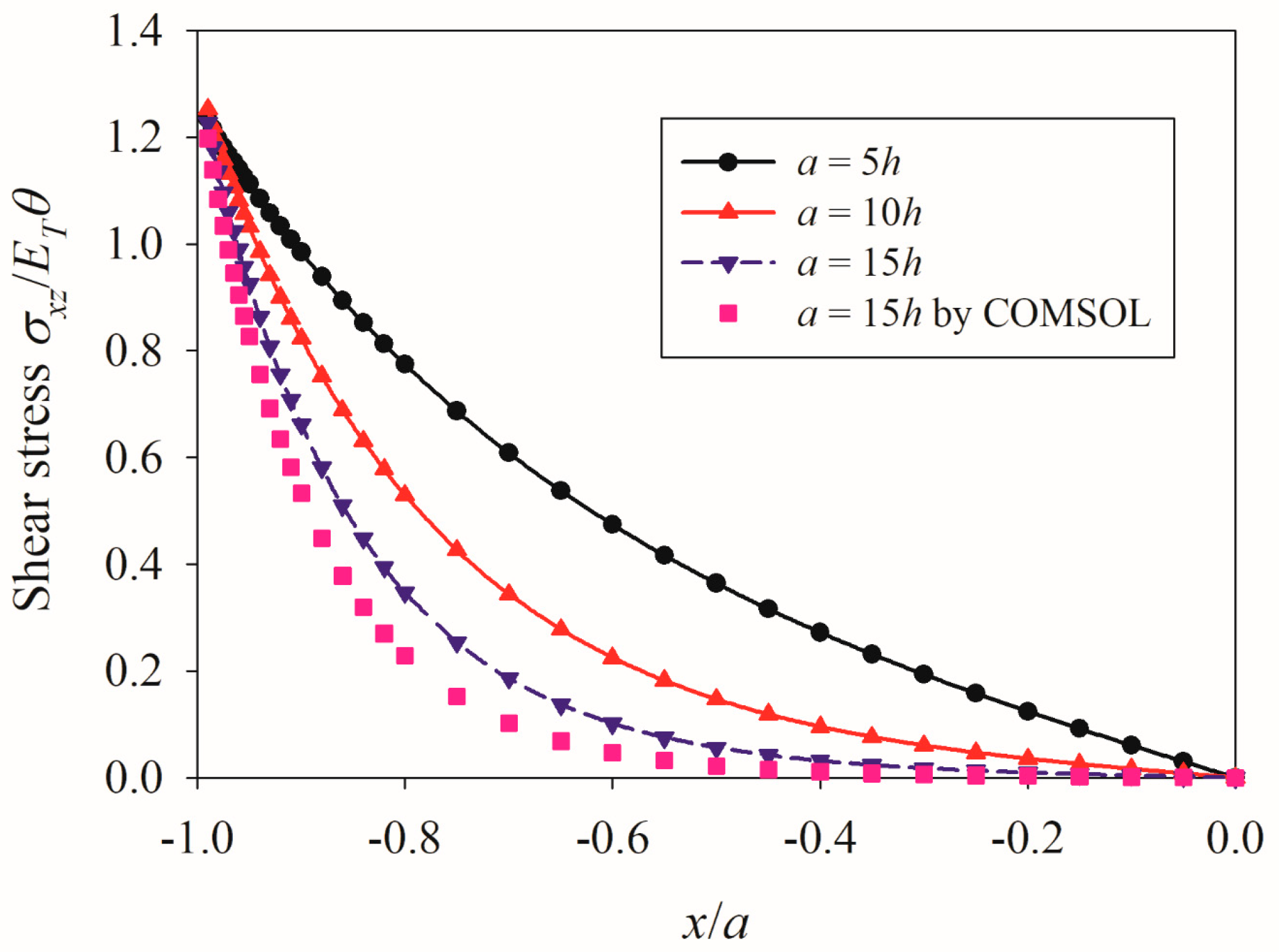
5.1. Validation of Numerical Simulations and Influence of the Aspect Ratio of QC Film

At first, a single 2D hexagonal QC film with an adhesive layer was investigated. As the problem is symmetrical, normal and shear stresses are, respectively, symmetrically and anti-symmetrically distributed about the middle point of 2D hexagonal QC film, only half of the distribution of stresses are plotted along QC film. To verify the theoretical solution, the numerical results of shear stress distributions were compared with the finite element software COMSOL for the aspect ratio a/h = 15, as illustrated in Figure 3. It is observed that the discrepancy between the theoretical solution and the finite element simulation is tiny. The difference is mainly attributed to the different models. In the theoretical derivation, a one-dimensional membrane model is used to simplify the problem. In contrast, a real two-dimensional model is simulated by the finite element method. Therefore, when the aspect ratio of QC film is large enough, its length is usually at least one order of magnitude higher than the thickness of the QC film; our proposed solution is accurate and in good agreement with the finite element simulations. It is shown in Figure 3 and Figure 4 that, as the increase of aspect ratio a / h , shear stress increases distinctly, making it more concentrated near the tips of QC film; meanwhile, the increasing aspect ratio raises the maximum value of axial stress. Therefore, an increasing aspect ratio results in easier damage to the system. This phenomenon coincides with a piezoelectric film [37] and is like a QC film system without an adhesive layer [39].

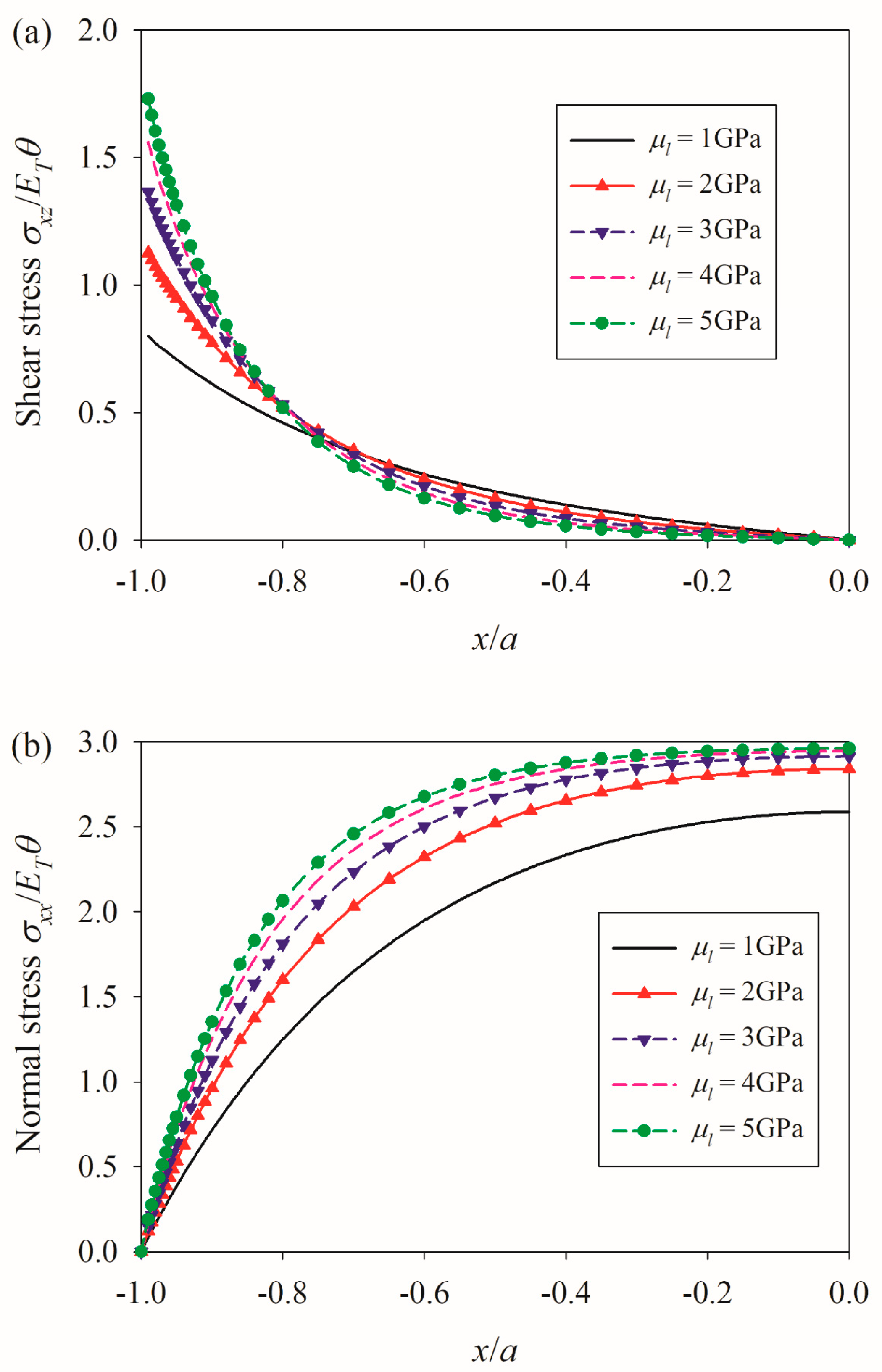
5.2. Influence of Material Mismatch

Figure 5 implies that different material mismatches have a significant influence on normal and shear stresses. In addition, a higher value of shear stress corresponds to a higher normal stress for a given substrate material. Thus, selecting a proper substrate material can restrict the level of stress and strengthen the bonding effect.

5.3. Influence of an Adhesive Layer

The shear modulus of epoxy is influenced by many factors, but it is mostly dependent on the crosslinking degree and the type and content of filler, ranging from 1 to 5 GPa. As shown in Figure 6a, an adhesive layer with a larger shear modulus leads to a higher value of shear stress near the ends of the QC film. Meanwhile, Figure 6b shows that the increase of shear modulus in an adhesive layer generates a higher level of normal stress as well. This is because an adhesive layer with a larger shear modulus is harder and can effectively transmit shear stress.
The thickness of an adhesive layer can also influence the behavior. As shown in Figure 7a, when the thickness of an adhesive layer grows, the concentration of shear stress near the ends of QC film is weakened dramatically and tends to a lower value. In the extreme case without an adhesive layer, the value of shear stress approaches infinity theoretically. This implies that the existence of an adhesive layer can greatly reduce stress concentration between the film and substrate, acting like a rubber gasket in engineering. Moreover, the normal stress in QC film decreases with increasing the thickness of an adhesive layer, as shown in Figure 7b.
Based on Figure 6 and Figure 7, it is seen that a thicker adhesive layer with a smaller shear modulus can reduce the level of stress and be helpful for designing a more reliable system.

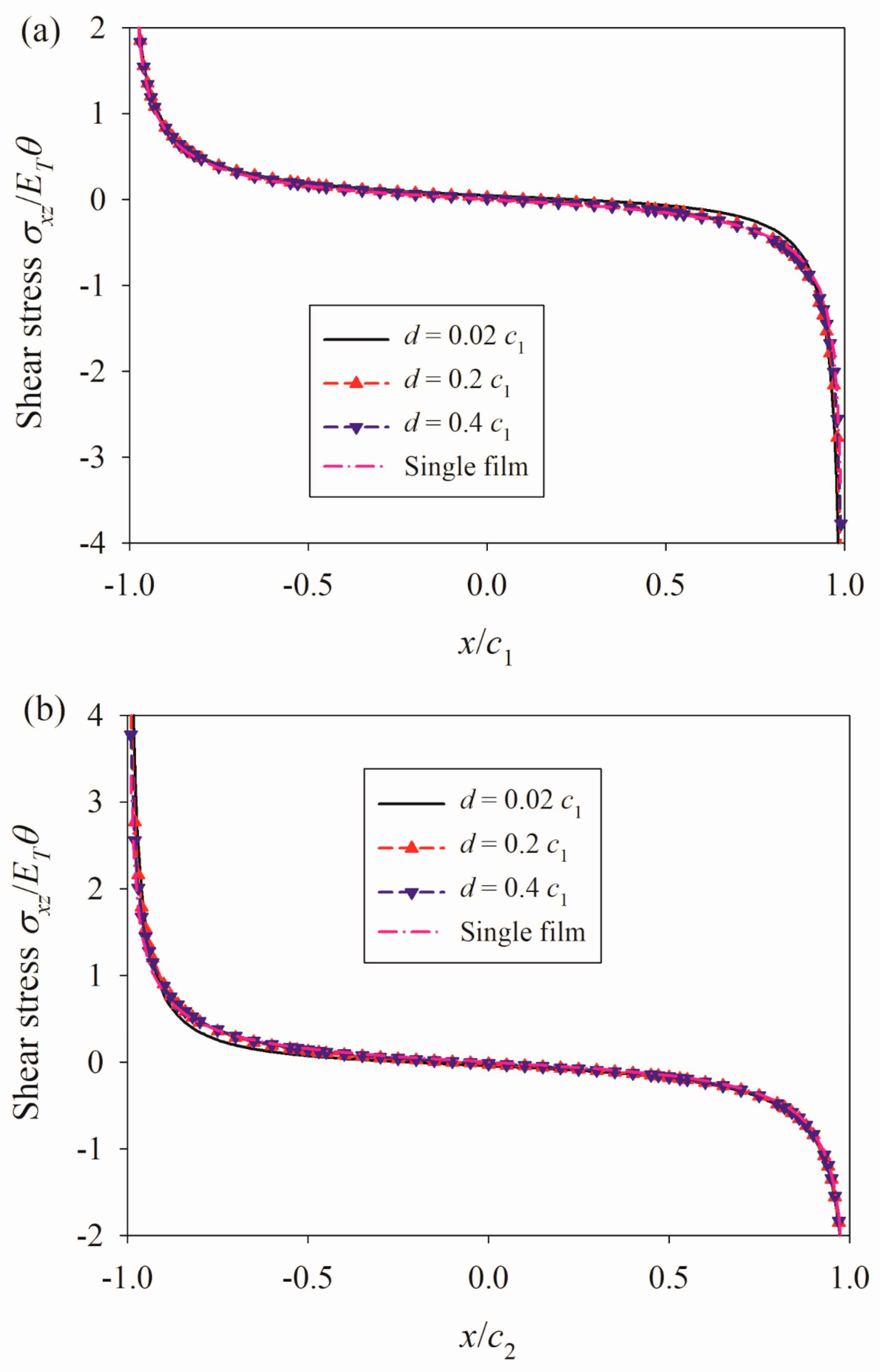
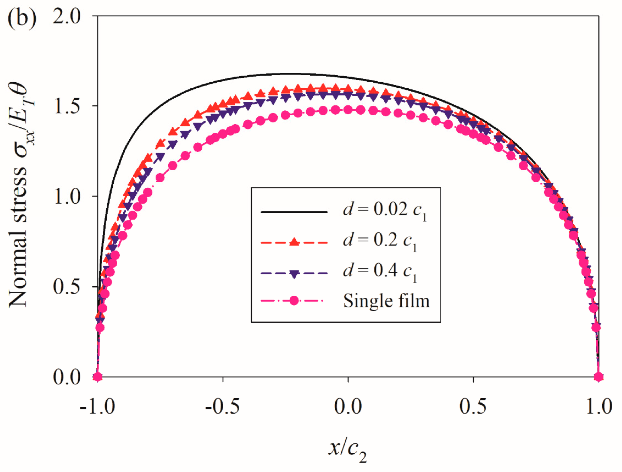
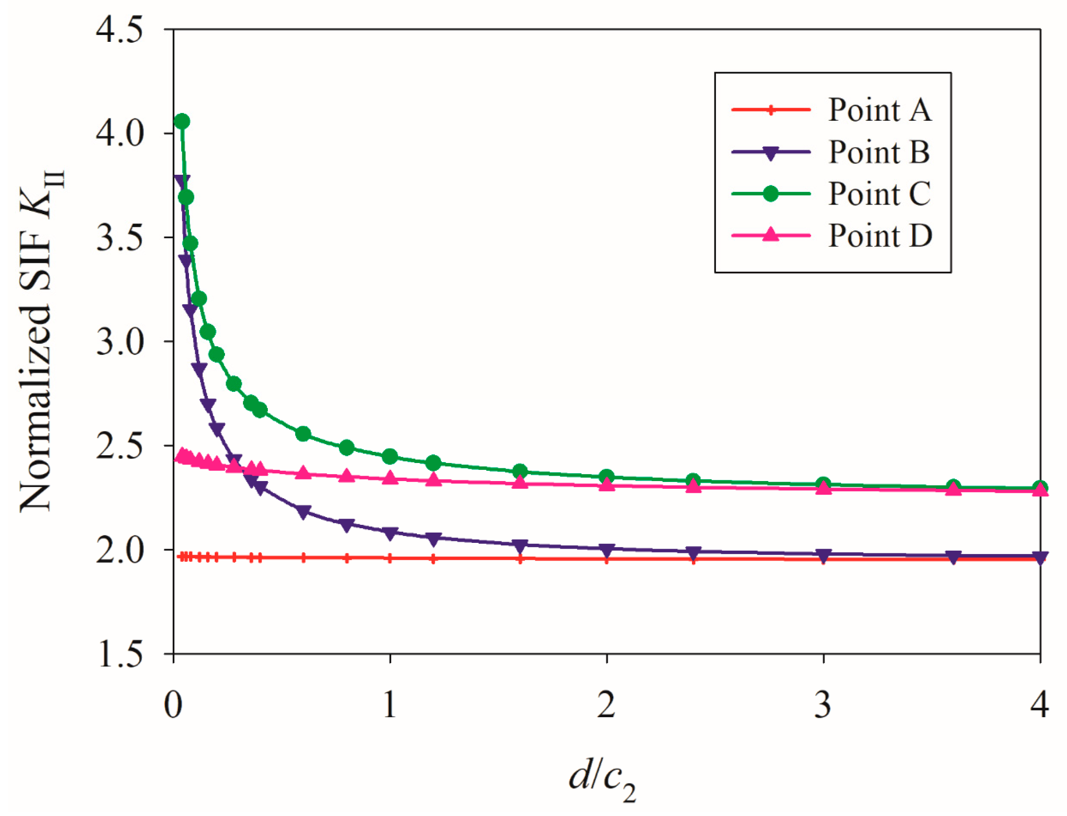
5.4. Influence of the Distance between Films without Adhesive Layers

Next, the shear and normal stresses of QC film were analyzed in the double-film model attaching to the substrate without adhesive layers. The substrate material was chosen and fixed as aluminum, with the geometries of c 1 = c 2 = 4 h a = 4 h b . First, let us consider the situation without adhesive layers. As observed in Figure 8, the distribution is no longer anti-symmetric due to the adjacent influence by the other film, and stress near the adjacent ends is higher than those away. When the two films get closer, the coupling effect grows dramatically; however, when they move away, the interaction effect is weakened, approaching the case of a single film. As shown in Figure 9, a similar phenomenon is also found for normal stress. As shown in Figure 10, SIFs at the adjacent ends are higher than those at the away ends, while these values start to decrease when the two films move away and finally approach the case of a single film.

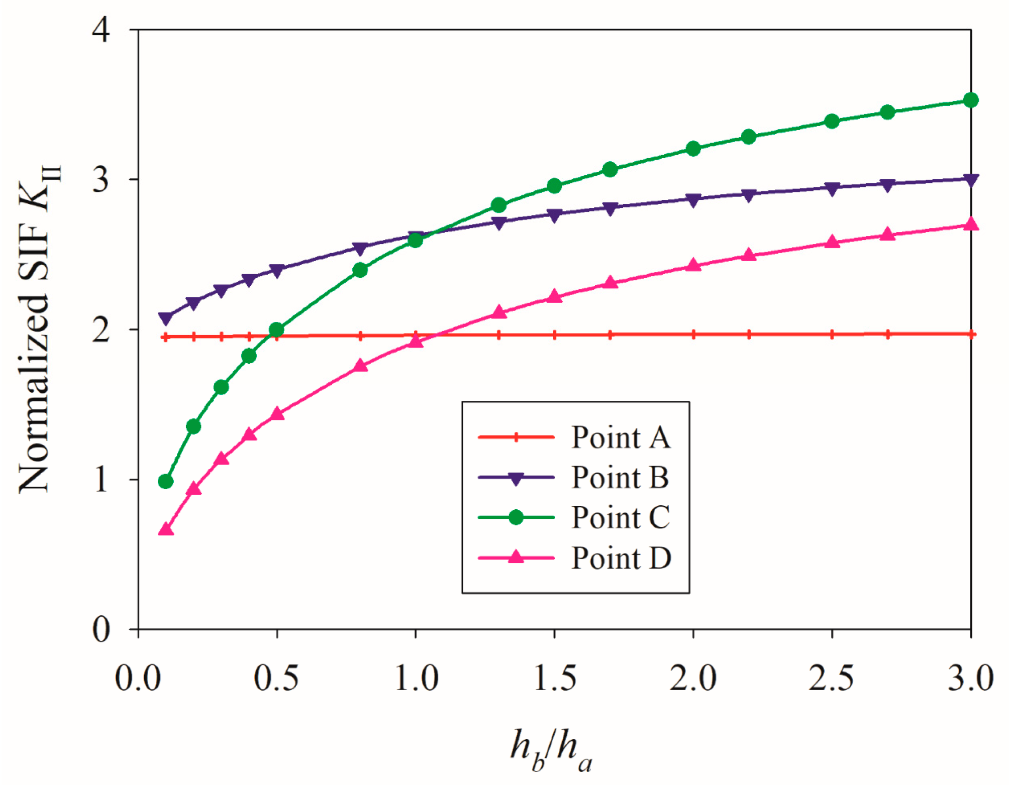
5.5. Influence of Film Thickness and Length without Adhesive Layers

As shown in Figure 11, when the ratio h b / h a increases, the values of SIFs at the ends in the right film perform a dramatic increase, while the values at the left one show a gentle growth. In general, the increase in film thickness greatly influences the values of SIFs and, thus, changes the most dangerous point in the system.
Figure 12 plots the values of SIFs at the ends of films versus the ratio of film thickness. It is concluded that, as the length of the left film increases, all the SIFs increase and gradually tend to a steady level. Meanwhile, the values of SIFs in the longer film are higher than those in the shorter one. However, the influence of film length is generally weak, and the biggest difference is roughly 2.2%.

5.6. Influence of Adhesive Layers in a Double Film Model

Taking an adhesive layer into account, we studied two films with the same length and thickness. As it is symmetric, the right QC film was only chosen. As seen in Figure 13a, there is no obvious difference when the distance changes, which is close to the situation of one single film. Compared with Figure 8, the existence of an adhesive layer acts like a “soft cushion” and greatly weakens the interaction effect. Such an influence can also be found in normal stress, as illustrated in Figure 13b compared with Figure 9. Further study confirms that the thicker and softer the adhesive layer, the weakening effect is more obvious. The adhesive layer can be treated as a “soft cushion”. Thus, the problem is close to a single film case. However, it is worth noting that the conclusion is not applicable to the case when the stiffness of an adhesive layer is sufficiently large.

6. Conclusions

The interface behavior of 2D hexagonal QC films induced by temperature change with and without adhesive layers was briefly studied. Based on the membrane assumption, the governing integral–differential equations for QC films in terms of interfacial shear stresses were obtained and numerically solved. In numerical simulations, the influencing factors on the interfacial behavior were comprehensively discussed. It is found that the aspect ratio of films, material mismatch, adhesive layer as well as the interaction between films can all greatly influence the mechanical performance of the QC film systems. Some main conclusions are obtained as follows.
(1) A high aspect ratio makes the system more easily damaged, and the proper selection of substrate material can restrict the stress level and strengthen the bonding effect of QC film.
(2) The adhesive layer can be treated as a “soft cushion”, which can greatly weaken the localized stress concentration near the ends of QC films. Meanwhile, a thicker adhesive layer with a smaller shear modulus reduces the level of stress and fracture.
(3) In the case without an adhesive layer, the point at the adjacent end of a longer film in a double-film system is more dangerous than other points due to the interaction effect. However, the existence of adhesive layers can greatly alleviate the interaction influence.

Author Contributions

Methodology, H.D.; investigation, W.Z.; resources, H.D. and C.L.; writing—original draft, H.D.; writing—review and editing, C.L.; supervision, C.F. and M.Z. All authors have read and agreed to the published version of the manuscript.

Funding

This work has been supported by the National Natural Science Foundation of China (No. 11902293 and 12272353) and the China Postdoctoral Science Foundation (No. 2019M652563).

Institutional Review Board Statement

Not applicable.

Informed Consent Statement

Not applicable.

Data Availability Statement

Data is contained within the article.

Conflicts of Interest

The authors declare no conflicts of interest.

References

  1. Dubois, J. Properties and applications of quasicrystals and complex metallic alloys. Chem. Soc. Rev. 2012, 41, 6760–6777. [Google Scholar] [CrossRef]
  2. Balbyshev, V.N.; King, D.J.; Khramov, A.; Kasten, L.S.; Donley, M.S. Investigation of quaternary Al-based quasicrystal thin films for corrosion protection. Thin Solid. Film. 2004, 447, 558–563. [Google Scholar] [CrossRef]
  3. Elina, H.S. Microstructure, fabrication and properties of quasicrystalline Al-Cu-Fe alloys: A review. J. Alloys Compd. 2004, 363, 150–174. [Google Scholar]
  4. Dubois, J.M.; Kang, S.S.; Vonstebut, J. Quasi-crystalline low-friction coatings. J. Mater. Sci. Lett. 1991, 10, 537–541. [Google Scholar] [CrossRef]
  5. Dubois, J.M. New prospects from potential applications of quasicrystalline materials. Mater. Sci. Eng. A 2000, 294, 4–9. [Google Scholar] [CrossRef]
  6. Ustinov, A.I.; Polischuk, S.S. Analysis of the texture of heterogeneous Al-Cu-Fe coatings containing quasicrystalline phase. Scripta Mater. 2002, 47, 881–886. [Google Scholar] [CrossRef]
  7. Guo, X.P.; Chen, J.F.; Yu, H.L.; Liao, H.L.; Coddet, C. A study on the microstructure and tribological behavior of cold-sprayed metal matrix composites reinforced by particulate quasicrystal. Surf. Coatings Technol. 2015, 268, 94–98. [Google Scholar] [CrossRef]
  8. Mora, J.; Garcia, P.; Muelas, R.; Agüero, A. Hard quasicrystalline coatings deposited by HVOF thermal spray to reduce ice accretion in aero-structures components. Coatings 2020, 10, 290. [Google Scholar] [CrossRef]
  9. Ramakrishnan, A.; Kesavan, K.K.; Chavhan, S.; Nagar, M.R.; Jou, J.H.; Chen, S.W.; Hsiao, H.W.; Zuo, J.M.; Huang, L.Y. Liquid exfoliation of decagonal quasicrystals and its light out-coupling performance in organic light-emitting devices. Adv. Photon-Res. 2020, 1, 2000042. [Google Scholar] [CrossRef]
  10. Mercier, T.M.; Rahman, T.; Krishnan, C.; Khorani, E.; Shaw, P.J.; Pollard, M.E.; Boden, S.A.; Lagoudakis, P.G.; Charlton, M. High symmetry nano-photonic quasi-crystals providing novel light management in silicon solar cells. Nano Energy 2021, 84, 105874. [Google Scholar] [CrossRef]
  11. Varadarajan, V.; Shekar, C. Fabrication of two-dimensional photonic quasi- crystals with 18- and 36- fold by holography for solar application. Iet Optoelectron. 2016, 10, 217–220. [Google Scholar] [CrossRef]
  12. Wang, S.; Sun, X.H.; Li, W.Y.; Liu, W.; Jiang, L.; Han, J. Fabrication of photonic quasicrystalline structures in the sub-micrometer scale. Superlattice Microst. 2016, 93, 122–127. [Google Scholar] [CrossRef]
  13. Zhong, J.B.; Chen, Y.J.; Teng, L.L.; Shao, X.J.; Han, B.; Yan, F. Research progress on Al based quasicrystal films/coatings. China Surf. Eng. 2021, 34, 105–116. [Google Scholar]
  14. Altidis, J.D.; Lima, S.J.G.; Gomes, R.M.; Sampaio, E.M.; Torres, S.M.; De Barros, S. Adhesion tests using epoxy quasicrystal composites. J. Adhes. Sci. Technol. 2012, 26, 1443–1451. [Google Scholar] [CrossRef]
  15. Lanzoni, L.; Radi, E. Thermally induced deformations in a partially coated elastic layer. Int. J. Solids Struct. 2009, 46, 1402–1412. [Google Scholar] [CrossRef]
  16. Aleksandrov, V.M. Two problems with mixed boundary conditions for an elastic orthotropic strip. J. Appl. Math. Mech. 2006, 70, 128–138. [Google Scholar] [CrossRef]
  17. Qi, K.; Yang, Y.; Hu, G.F.; Lu, X.; Li, J.D. Thermal expansion control of composite coatings on 42CrMo by laser cladding. Surf. Coatings Technol. 2020, 397, 125983. [Google Scholar] [CrossRef]
  18. Akisanya, A.R.; Fleck, N.A. The edge cracking and decohesion of thin films. Int. J. Solids Struct. 1994, 31, 3175–3199. [Google Scholar] [CrossRef]
  19. Yu, H.H.; He, M.Y.; Hutchinson, J.W. Edge effects in thin film delamination. Acta Mater. 2001, 49, 93–107. [Google Scholar] [CrossRef]
  20. Guler, M.A.; Gulver, Y.F.; Nart, E. Contact analysis of thin films bonded to graded coatings. Int. J. Mech. Sci. 2012, 55, 50–64. [Google Scholar] [CrossRef]
  21. Arutiunian, N.K. Contact problem for a half-plane with elastic reinforcement. J. Appl. Math. Mech. 1968, 32, 652–665. [Google Scholar] [CrossRef]
  22. Erdogan, F.; Gupta, G.D. The Problem of an Elastic Stiffener Bonded to a Half Plane. J. Appl. Mech. 1971, 38, 937–941. [Google Scholar] [CrossRef]
  23. Hu, S.M. Film-edge-induced stress in substrates. J. Appl. Phys. 1979, 50, 4661–4666. [Google Scholar] [CrossRef]
  24. Shield, T.W.; Kim, K.S. Beam theory models for thin film segments cohesively bonded to an elastic half space. Int. Int. J. Solids Struct. 1992, 29, 1085–1103. [Google Scholar] [CrossRef]
  25. Chen, P.J.; Chen, S.H.; Peng, J.; Gao, F.; Liu, H. The interface behavior of a thin film bonded imperfectly to a finite thickness gradient substrate. Eng. Fract. Mech. 2019, 217, 106529. [Google Scholar] [CrossRef]
  26. Chen, P.J.; Peng, J.; Liu, H.; Gao, F.; Guo, W. The electromechanical behavior of a piezoelectric actuator bonded to a graded substrate including an adhesive layer. Mech. Mater. 2018, 123, 77–87. [Google Scholar] [CrossRef]
  27. Li, D.K.; Chen, P.J.; Huang, Z.X.; Liu, H.; Chen, S.H. The interfacial behavior of a thermoelectric thin-film bonded to an orthotropic substrate. Int. J. Solids Struct. 2023, 267, 112160. [Google Scholar] [CrossRef]
  28. Liu, M.; Lu, B.; Shi, D.L.; Zhang, J.Q. Two-dimensional analysis of progressive delamination in thin film electrodes. Acta Mech. Sin. 2018, 34, 359–370. [Google Scholar] [CrossRef]
  29. Alinia, Y.; Güler, M.A. On the problem of an axisymmetric thin film bonded to a transversely isotropic substrate. Int. J. Solids Struct. 2022, 248, 111636. [Google Scholar] [CrossRef]
  30. Abbaszadeh-Fathabadi, S.A.; Alinia, Y.; Güler, M.A. On the mechanics of a double thin film on a finite thickness substrate. Int. J. Solids Struct. 2023, 279, 112349. [Google Scholar] [CrossRef]
  31. Zhou, Y.T.; Tian, X.J.; Ding, S.H. Microstructure size-dependent contact behavior of a thermoelectric film bonded to an elastic substrate with couple stress theory. Int. J. Solids Struct. 2022, 256, 111982. [Google Scholar] [CrossRef]
  32. Radi, E. A loaded beam in full frictionless contact with a couple stress elastic half-plane: Effects of non-standard contact conditions. Int. J. Solids Struct. 2021, 232, 111175. [Google Scholar] [CrossRef]
  33. Radi, E.; Nobili, A.; Guler, M.A. Indentation of a free beam resting on an elastic substrate with an internal lengthscale. Eur. J. Mech. A-Solid. 2023, 100, 104804. [Google Scholar] [CrossRef]
  34. Qing, X.L.; Chan, H.L.; Beard, S.J.; Ooi, T.K.; Marotta, S.A. Effect of adhesive on the performance of piezoelectric elements used to monitor structural health. Int. J. Adhes. Adhes. 2006, 26, 622–628. [Google Scholar] [CrossRef]
  35. Rabinovitch, O. Piezoelectric control of edge debonding in beams strengthened with composite materials: Part I—Analytical modeling. J. Compos. Mater. 2007, 41, 525–546. [Google Scholar] [CrossRef]
  36. Rabinovitch, O. Piezoelectric control of edge debonding in beams strengthened with composite materials: Part II—Failure criteria and optimization. J. Compos. Mater. 2007, 41, 657–677. [Google Scholar] [CrossRef]
  37. Jin, C.; Wang, X. Analytical modelling of the electromechanical behavior of surface-bonded piezoelectric actuators including the adhesive layer. Eng. Fract. Mech. 2011, 78, 2547–2562. [Google Scholar] [CrossRef]
  38. Yu, H.; Wang, X. Modelling and simulation of surface-bonded piezoelectric actuators with bending effects. J. Intell. Mater. Syst. Struct. 2017, 28, 507–520. [Google Scholar] [CrossRef]
  39. Dang, H.Y.; Qi, D.P.; Zhao, M.H.; Fan, C.Y.; Lu, C.S. The thermally induced interfacial behavior of a thin two-dimensional decagonal quasicrystal film. Int. J. Fract. 2023. [Google Scholar] [CrossRef]
  40. Dang, H.Y.; Qi, D.P.; Zhao, M.H.; Fan, C.Y.; Lu, C.S. Thermal-induced interfacial behavior of a thin one-dimensional hexagonal quasicrystal film. Appl. Math. Mech-Engl. 2023, 44, 841–856. [Google Scholar] [CrossRef]
  41. Yang, L.Z.; Zhang, L.L.; Song, F.; Gao, Y. General solutions for three-dimensional thermoelasticity of two-dimensional hexagonal quasicrystals and application. J. Thermal Stresses. 2014, 37, 363–379. [Google Scholar] [CrossRef]
  42. Fan, T.Y.; Xie, L.; Fan, L.; Wang, Q. Interface of quasicrystal and crystal. Chinese Phys. B 2011, 20, 076102. [Google Scholar] [CrossRef]
  43. Muskhelishvili, N.I. Some Basic Problems of the Mathematical Theory of Elasticity; Springer: Berlin/Heidelberg, Germany, 1953. [Google Scholar]
  44. Li, X.Y.; Wang, Y.W.; Li, P.D.; Kang, G.Z.; Müller, R. Three-dimensional fundamental thermo-elastic field in an infinite space of two-dimensional hexagonal quasi-crystal with a penny-shaped/half-infinite plane crack. Theory Appl. Fract. Mech. 2017, 88, 18–30. [Google Scholar] [CrossRef]
Figure 1. An illustration of a 2D hexagonal QC film with an adhesive layer.
Coatings 14 00354 g001
Figure 2. Illustration of two 2D hexagonal QC films with adhesive layers.
Coatings 14 00354 g002
Figure 3. Distribution of shear stress for different aspect ratios with the fixed ratio h f / h l = 5 , and the shear modulus μ l = 5   G P a .
Coatings 14 00354 g003
Figure 4. Distribution of normal stress for different aspect ratios with the fixed ratio h f / h l = 5 , and the shear modulus μ l = 5   G P a .
Coatings 14 00354 g004
Figure 5. Distribution of stresses for different substrate materials with the fixed aspect ratios a / h f = 5 and h f / h l = 5 , and the shear modulus μ l = 5   G P a (a) shear stress, (b) normal stress.
Coatings 14 00354 g005
Figure 6. Distribution of (a) shear and (b) normal stresses for different shear moduli of an adhesive layer with the fixed aspect ratios of a / h f = 10 and h f / h l = 10 .
Coatings 14 00354 g006
Figure 7. Distribution of (a) shear and (b) normal stresses for different ratios h f / h l with a fixed aspect ratio a / h f = 10 .
Coatings 14 00354 g007
Figure 8. Distributions of shear stresses in QC films, i.e., (a) film 1, (b) film 2, for different distances.
Coatings 14 00354 g008
Figure 9. Distribution of normal stresses in QC films, i.e., (a) film 1, (b) film 2, for different distances.
Coatings 14 00354 g009aCoatings 14 00354 g009b
Figure 10. Normalized SIF KII at the ends of QC films versus the film distance with fixed h b = 2 h a , c 1 = 15 h a , and c 2 = 2.5 h b .
Coatings 14 00354 g010
Figure 11. Normalized SIF KII at the ends of QC films versus the ratio of film thickness with fixed c 1 = 15 h a , c 2 = 5 h a , and d = 0.6 h a .
Coatings 14 00354 g011
Figure 12. Normalized SIF KII at the ends of QC films versus the ratio of film length with fixed h a = h b , c 2 = 5 h a , and d = 0.6 h a .
Coatings 14 00354 g012
Figure 13. Distributions of (a) shear and (b) normal stresses in QC film 2 for different film distances with fixed h a = h b , and c 1 = c 2 = 4 h a .
Coatings 14 00354 g013
Table 1. The material properties of substrate materials.
Material μ (GPa)vα (10–6/K)
Al30.50.337.2
Cu47.80.3517.0
ZrO277.50.2910.6
Disclaimer/Publisher’s Note: The statements, opinions and data contained in all publications are solely those of the individual author(s) and contributor(s) and not of MDPI and/or the editor(s). MDPI and/or the editor(s) disclaim responsibility for any injury to people or property resulting from any ideas, methods, instructions or products referred to in the content.

