Article

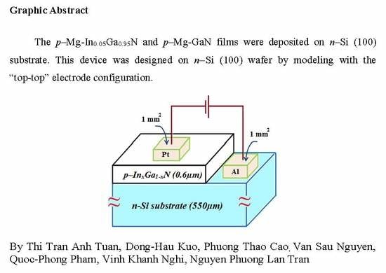
Electrical Characterization of RF Reactive Sputtered p–Mg-InxGa1−xN/n–Si Hetero-Junction Diodes without Using Buffer Layer

1
School of Basic Sciences, Tra Vinh University, Tra Vinh 87000, Vietnam
2
Department of Materials Science and Engineering, National Taiwan University of Science and Technology, Taipei 10607, Taiwan
3
School of Engineering and Technology, Tra Vinh University, Tra Vinh 87000, Vietnam
4
College of Engineering and Technology, Can Tho University, Can Tho 94000, Vietnam
*
Authors to whom correspondence should be addressed.
Submission received: 30 August 2019 / Revised: 17 October 2019 / Accepted: 21 October 2019 / Published: 25 October 2019
(This article belongs to the Special Issue Advanced Strategies in Thin Film Engineering by Magnetron Sputtering)

Abstract

:
The modeling of p–InxGa1−xN/n–Si hetero junction diodes without using the buffer layer were investigated with the “top-top” electrode. The p–Mg-GaN and p–Mg-In0.05Ga0.95N were deposited directly on the n–Si (100) wafer by the RF reactive sputtering at 400 °C with single cermet targets. Al and Pt with the square size of 1 mm2 were used for electrodes of p–InxGa1−xN/n–Si diodes. Both devices had been designed to prove the p-type performance of 10% Mg-doped in GaN and InGaN films. By Hall measurement at the room temperature (RT), the holes concentration and mobility were determined to be Np = 3.45 × 1016 cm−3 and µ = 145 cm2/V·s for p–GaN film, Np = 2.53 × 1017 cm−3, and µ = 45 cm2/V·s for p–InGaN film. By the I–V measurement at RT, the leakage currents at −5 V and turn-on voltages were found to be 9.31 × 10⁻⁷ A and 2.4 V for p–GaN/n–Si and 3.38 × 10⁻⁶ A and 1.5 V for p–InGaN/n–Si diode. The current densities at the forward bias of 20 V were 0.421 and 0.814 A·cm−2 for p–GaN/n–Si and p–InGaN/n–Si devices. The electrical properties were measured at the temperature range of 25 to 150 °C. By calculating based on the TE mode, Cheungs’ and Norde methods, and other parameters of diodes were also determined and compared.

Graphical Abstract

1. Introduction

GaN and InGaN have excellent characteristics such as high conductivity and high mobility. The development and creation of p–layer GaN and InGaN materials involve one of the important technologies in designing electronic devices [1,2,3,4,5]. The investigation of high-quality doping in GaN and InGaN semiconductors by incorporating elements such as Zn, and Cu, Mg for p–GaN behavior, and its alloys had reported [4,5,6,7,8]. The success of Mg doping in forming p-InxGa1−xN films is an important factor for developing electric devices, a photo detector, and solar cell devices [7,8,9,10]. Si wafer has often been used for the growth of GaN, InGaN, and their alloys for applications in photo-detector, solar cells, and electronic devices. The combination between n–InGaN layers and n–Si wafers were studied to improve the interface layers by using an assortment of approaches [11,12,13,14]. For fabricated electronic devices, the growth of the InGaN layer on n–Si wafers were studied to improve the interface layers by using a variety of approaches [15,16,17,18,19,20]. Lee at al. studied electrical properties of a nanowire n–GaN/p–Si device by forming dielectrophoretic alignment. At the current density of 10–60 A/cm2, the diode was well-defined with a forward voltage drop of 1.2–2.0 V and high resistance in the range of 447 KΩ [17]. Li et al. used the RF sputtering method to deposit the Mg-doped GaN films on the Si substrate and design the homo junction GaN diodes. By testing the I–V measurement, the turn-on voltages of diodes were 2.3 and 2.1 V for as-deposited and 500 °C-annealed sample, respectively [21]. Vinay Kabra et al. investigated the p–ZnO/n–Si hetero junction diode by using a dip coating technique. Their electrical properties showed the highly rectifying, with a rectification ratio of 101 at 3 V [22]. Mohd Yusoff et al. reported the p–n junction diode based on GaN grown on the AlN/Si (111) substrate and annealed samples at 700 °C. The ideality factors of their diodes decreased from 19.68 to 15.14, with the testing temperature increasing from 30 to 104 °C [23]. In previous work, the Mg–doped InxGa1−xN films had been deposited on Si (100) substrates by RF reactive sputtering. The Mg–InxGa1−xN films had the p–type conduction at x ≤ 0.075. The p–Mg–In0.05Ga0.95N/n–GaN diode was shown the leakage current of 2.7 × 10⁻⁶ A, turn-on voltage of 1.8 V, and breakdown voltage of 6.8 V at the RT [12].
All previous groups often investigated the p–GaN films and their alloys by using MOCVD above 800 °C and other methods. The sputtered technique with the low temperature at and below 400 °C has been hardly declared. Furthermore, there is no report on the electrical properties of p–Mg-InxGa1−xN/n–Si diodes without using buffer layers. In this study, to prove the success of Mg doping in the p–GaN and the p–InGaN films, the modeling of p–Mg-InxGa1−xN/n–Si hetero junction diodes was designed by using the RF reactive sputtering. This method was chosen to design diodes due to the benefits of low sputtered-temperature, low cost, and safe working atmosphere [7,13,15]. The n–Si (100) wafer was also used for its low cost, large wafer size, and easy availability [18,22,24]. The electrical characteristics of devices were calculated by the thermionic emission (TE) mode at different testing temperatures [3,12,13].

2. Materials and Methods

Figure 1 shows the structural modeling of a p–InxGa1−xN/n–Si hetero junction diode. This device was designed on the n−Si (100) wafer by modeling with the “top-top” electrode. The p–Mg-In0.05Ga0.95N and p–Mg-GaN films were deposited together on the n–Si (100) and SiO2/Si (100) substrate. The n–Si (100) wafer had sheet resistance of ~1–10 Ω·cm, diameter of 2 inches, thickness of ~550 μm, and the polished surface. Sputtered-InxGa1−xN films on SiO2/Si substrate were used for testing Hall measurement and SEM analysis.
For the p–GaN film, the sputtering cermet target was made by hot pressing with the mixture of metallic Mg, Ga powders, and GaN powder. The [Mg]/([Ga]+[Mg]) molar ratio in each cermet target was reserved at 10%. Similar for p–InGaN film, the [Mg]/([In]+[Ga]+[Mg]) molar ratio in each cermet target was also kept at 10%. The [In]/([In]+[Ga]+[Mg]) molar ratios was 5%. The p–Mg–InxGa1−xN films (with x~0 and 0.05) were deposited on n–Si (100) substrates at 400 °C for 25 min by RF reactive sputtering. Both Mg–InxGa1−xN targets were sputtered with RF power of 150W under the gas mixture of Ar and N2, which remained at 5 sccm for each.
The pure Aluminum (99.99%) and Platinum (99.99%) targets were used for making the electrodes for p–InxGa1−xN/n–Si hetero junction diodes. By using steel masks with the square size of 1 mm2, these electrodes were deposited at 200 °C, with RF power of 80W for 30 min on top of p–InxGa1−xN films and n–Si substrate. The detail procedure for creating the p–GaN and p–InGaN films, made by RF reactive sputtering, can be referred to our previous works [10,11,12,21].
In this work, our diodes were designed at the low sputtered-temperature and high pressure. The holes’ concentration, electrical conductivities, and mobilities of p–Mg-InxGa1−xN films and n–Si wafer were measured by a Hall measurement (HMS–2000, Ecopia, Tokyo, Japan). Scanning electron microscopy (SEM, JSM–6500F, JEOL, Tokyo, Japan) was used to observe the surface morphology of p–InxGa1−xN films. Energy dispersive spectrometer (EDS, JSM–6500F) equipped on SEM was used for composition analysis of films. The IV characteristics of p–InxGa1−xN/n–Si diodes were measured by using Semiconductor Device Analyzer (Agilent, B1500A, Tokyo, Japan) with the different temperature. All parameters of diodes were calculated by following the equations of the TE mode as well as the Cheungs’ and Norde method.

3. Results and Discussion

3.1. Structural and Electrical Characteristics

The carrier concentration (Np) and carrier mobility (µ) of n–Si wafer were found to be Np = 4.7 × 1015 cm−3 and = 196 cm2/V.s when measuring the Hall effect at room temperature (RT). The holes concentration (Np) and mobility (µ) were also determined to be Np = 3.45 × 1016 cm−3, µ = 145 cm2/V·s for p–GaN film, and Np = 2.53 × 1017 cm−3, µ = 45 cm2/V·s for p–InGaN film, respectively. By SEM analysis, the thicknesses of Pt and Al layers were ~250 nm and the thickness of both p–InxGa1−xN films was ~0.6 μm.

3.2. The Energy Band Diagram

Figure 2 displays the energy band diagram of a p–In0.5Ga0.95N/n–Si diode as an example. Our band gap (Eg) of Mg-doped In0.5Ga0.95N (Mg of 10%) films at 400 °C-deposition were 2.92 eV. The Eg was reduced by increasing In content in InxGa1−xN [10,21]. In a similar result, Wagner et al. reported the composition dependence of the band gap energy of the strained InxGa1xN layers grown by MOCVD. The energy Eg of InxGa1−xN decreased from 3.43 to 3.28 eV with the increasing in ratio from 0.02 to 0.15 [25]. The band gap values of nSi was also found to be 1.12 eV. The electron affinities χ of pInGaN and nSi were 4.20 eV and 4.05 eV, respectively [6,24]. According to the band gap values of pIn0.5Ga0.95N and nSi (2.92 and 1.12 eV), the barrier ΔEc for electrons was followed by ΔEc = χpInGaN − χSi and the barrier ΔEv for holes was calculated by ΔEv = Eg(InGaN)Eg(Si) + ΔEc (Figure 2). As a result, the energy band diagram showed a small conduction band offset of 0.15 eV and a large valance band offset of 1.95 eV [22,24,25,26]. Therefore, the electrons’ injection from n–Si into p–InxGa1−xN will be easier than the holes’ injection from p–InxGa1−xN into n–Si because the energetic barrier ΔEv of holes is many times higher than the barrier ΔEc of electrons. With the existing space charge layer at the forward bias, the current is limited. However, the depletion width will decrease because of the low potential barrier, and the current will increase easily by increasing the voltage [6,27,28].

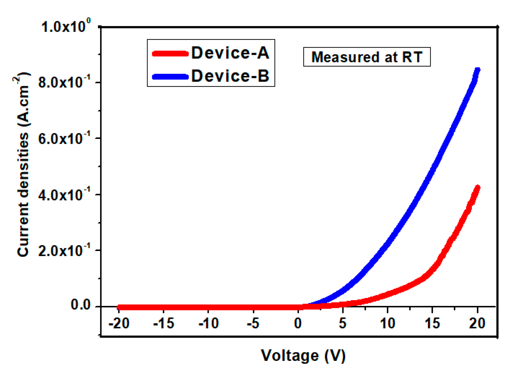
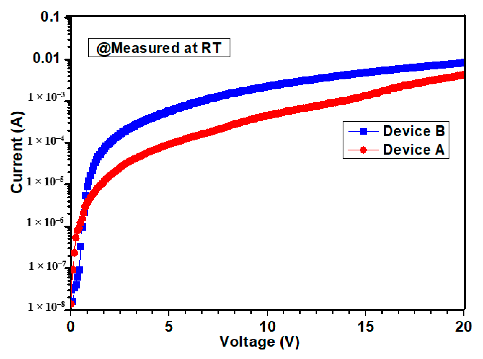
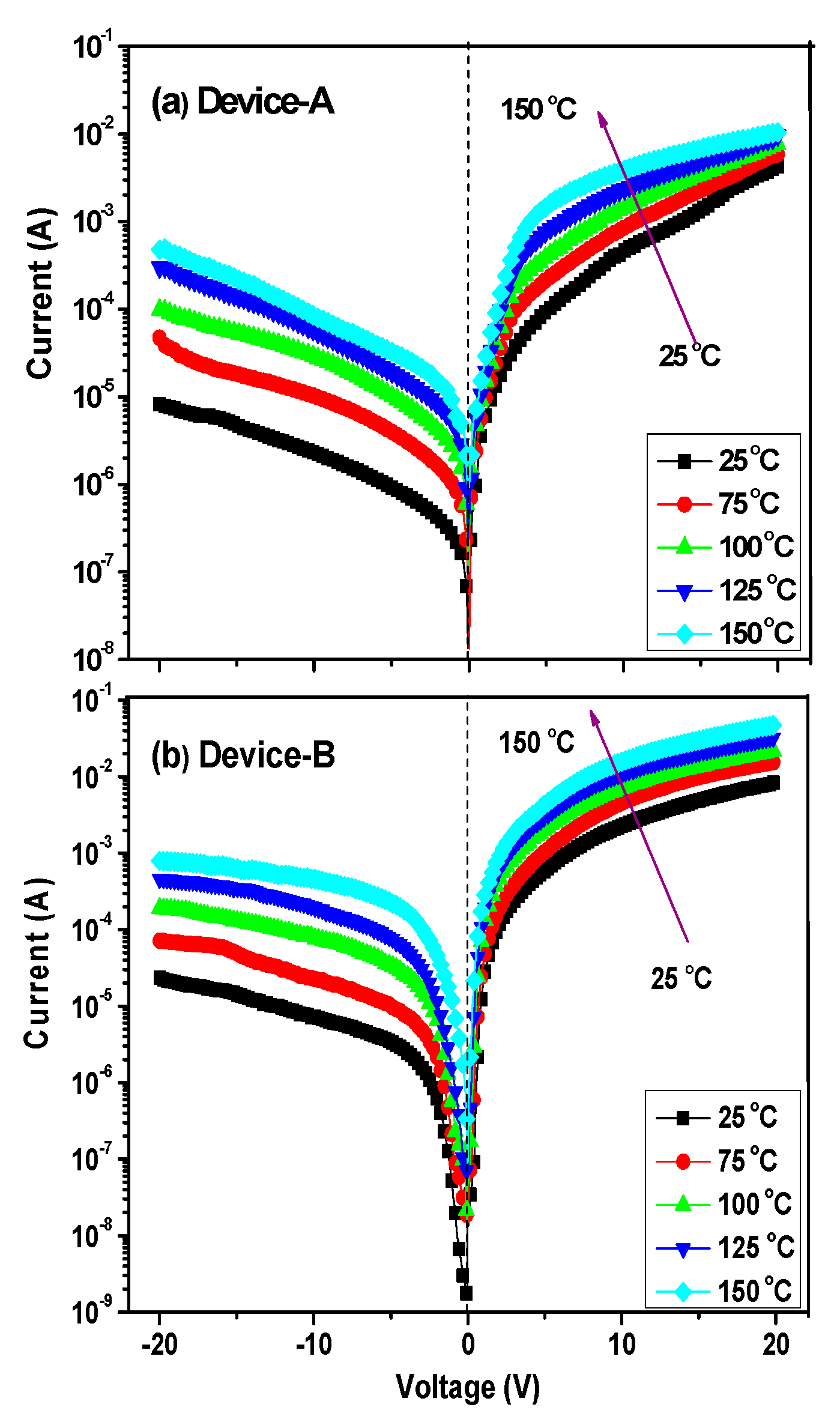
3.3. I–V Measurements

Figure 3 shows the current density–voltage characteristics of p–GaN/n-Si (device-A) and p–InGaN/n-Si (device-B) tested at RT based on a 1-mm2 contact. The applied voltage of measurement was extended from −20 V to +20 V for both devices. The current densities and the leakage current densities are found in the area of 1 cm2.
At the bias range of (−5 V, +5 V), the leakage current of diodes at −1 V and the turn-on voltages at RT were 1.43 × 10⁻⁷ A, 1.5 V (device-A) and 2.58 × 10⁻⁷ A, 2.4 V (device-B). Our devices had an improvement in the turn-on voltage with the increase in content in the p–InGaN layer.
With the wide voltage of (−20 V, +20 V), Figure 3 also shows the breakdown voltage was beyond the largest instrument capacity of ~20 V for both diodes. The leakage currents also were found to be 9.31 × 10⁻⁷ and 3.38 × 10⁻⁶ A at −5 V for (device-A) and (device-B), respectively. At the forward bias of 20 V, the current densities of diodes were 0.421 and 0.814 A·cm−2 for device-A and device-B, respectively. Higher holes concentration in the p–InGaN layer with the performance of the in ratio in p–InGaN leads to the higher current density of device-B. In addition, with the high conduction of electrodes, the forward current of diodes increased rapidly at the bias of (−20 V, +20 V). The rectification ratio (on/off) of diodes were also found to be 3.22 × 10⁴ (device-A) and 6.61 × 10⁴ (device-B), respectively.
Figure 4 shows the semilogarithmic IV characteristics of diodes under the forward bias, which were tested at the RT temperature. All parameters of diodes can be calculated by the thermionic-emission (TE) mode (for qV > 3 kT). They are given by the equations below [3,11,12].
I = I 0 [ exp q n k T ( V I R s ) ]
ϕ b = k T q l n ( A A * T 2 I 0 )
n = q k T ( d V dln I )
A * = 4 π q k 2 m * h 3
where A* is the effective Richardson constant, Rs is the series resistance, n is the ideality factor, Io is the saturation current, q is the electronic charge, A is the area of diode, ϕb is the barrier height, me is the free electron mass, m* is the effective electron mass, and h is the Plank constant [29,30,31]. In base Equation (4), the theoretical value of A* was 26.4 A·cm−2·K−2 for p–GaN (m* = 0.22me), and 23 A·cm−2·K−2 for p–InGaN (m* = 0.19me) [6,12,13].
As shown in Figure 4, the barrier height of diodes can be calculated from Io as the saturation current. Based on Equation (2), and from the plot of lnI versus V, the saturation current Io can be determined by intersecting the interpolated straight lines from the linear region with the current axis [12,20].
Figure 5a,b show the semi logarithmic IV characteristics of diodes were tested at the temperature range from 25 to 150 °C. From Figure 5, the leakage current of diode at −5 V increased from 9.39 × 10⁻⁷ A (device-A) and 3.38 × 10⁻⁶ (device-B) at 25 °C to 3.25 × 10⁻⁵ A (device-A) and 2.64 × 10⁻⁴ A (device-B) at 150 °C. Based upon Equations (1)–(3), the barrier height values were found to increase from 0.54 to 0.69 eV (device-A), and 0.50 to 0.62 eV (device-B), whereas the ideality factor n decreased from 5.9 to 4.8 (device-A), and 5.1 to 3.6 (devices-B) with testing temperatures ranging from 25 to 150 °C. These achieved parameters of diodes made by RF sputtering are similar to some previous works with the GaN-diodes made by MOCVD and techniques [1,3,18,28].
Similar to the analysis of the parameters for Schottky diodes, the effect of series resistance Rs will influence and change the ideality factor n. They can be determined by using Cheung’s method. It is given by the equation below [13,32,33].
d V d ( ln I ) = n k T q + I R S
Based on Equation (5) and the plot of the dV/d(lnI) versus I from Figure 6, the series resistance Rs and ideality n can be calculated the from the the slope and the intercept [11,33,34]. Table 1 shows all detailed parameters of the IV measurement for both devices tested at different temperatures. With the high Indium content, the Rs and n values of device-B were smaller than device-A. They showed 412 Ω and 5.3 at 25 °C and decreased them to 133 Ω and 3.8 at 150 °C.
By comparison, with Cheung’s method, the modified Norde function was also used to define the effective barrier height of diodes. It is followed by the equation below [12,13,34,35,36].
F ( V , I ) = V γ k T q ln ( I A A * T 2 )
The effective barrier height ϕB is followed by the equation below.
ϕ B = F ( V min ) + V min γ k T q
where the F(Vmin) is the minimum value of F(V,I), γ is the first integer (dimensionless) greater than n, and Vmin is the corresponding voltage at F(Vmin).
Figure 7a,b shows the plot of F(V,I) versus V of hetero junction diodes as a function of the different temperatures tested. By using Equations (6) and (7), the barrier height values were determined to be 0.56 eV (device-A) and 0.53 eV (device-B) at 25 °C, and reached 0.71 eV (device A) and 0.64 eV (device B) at 150 °C (Table 1).

4. Discussion

Table 1 showed the detailed comparisons of the IV measurements for both hetero junction diodes. The smallest leakage current of 9.31 × 10⁻⁷ A at −5 V was found in device-A tested at RT, while the smallest turn-on voltage was ~1.5 V. The highest current density of 0.814 A·cm−2 were found in device-B at the forward bias of 20 V. At the reverse bias, the breakdown voltage of both devices was strongly blocked with the value at −20 V. The forward current increased quickly with the occurrence of the in content in the p–InGaN layer. With a higher holes carrier concentration of 2.53 × 1017 cm−3 and a smaller band gap of 2.92 eV, device-B showed the small turn-on voltage of 1.5 V, barrier heights of 0.5 eV (Cheung’s method), and 0.53 eV (Norde method), compared with all parameters of device-A [20].
The ideality factor n of diodes decreased quickly, from 5.9 at 25 °C for device-A to 3.6 at 150 °C for device-B. For the Schottky diode, the turn-on voltage is often small, and the ideality factor n is <2 [2,3,13]. In our diodes, the ideality factors had high values because of the present high series’ resistances, which were calculated from the slope of the linear region in Cheung’s method. In addition, from the band diagram in Figure 2, the barrier ΔEv for holes was larger than that of ΔEc. Therefore, a higher valance band offset will have a high potential barrier, large turn-on voltage, high ideality factor, and high series resistance Rs. The high ideality factor of our diodes at RT also has been attributed to the high structural defect density, which serves as the trap-assisted generation-recombination centers. This procedure also influences the current transportation of hetero junction diodes [13,17,20]. The Rs values also reduced from 876 Ω at 25 °C (device-A) to 133 Ω at 150 °C (device-B). The generations of series resistance, interface states, and the voltage drop across the interfacial layer caused the slight difference between the ideality factor n calculated from the lnI vs V and dV/d(lnI) vs. I plots (Table 1).
Both hetero junction diodes had remarkable improvements as compared with some other homo and hetero junction diodes made by different techniques. Their deposition had epitaxial growth and was conducted at high temperatures above 800 °C by MOVCD [18,19,27,37,38,39]. Our devices had displayed the special IV characteristics, which can be attributed to the low-temperature deposited at −400 °C without using a buffer layer. Both our diodes showed the breakdown voltage above 20 V for a 1 mm2-sized contact.
K.E.F. Keskenler et al. made the n–ZnO/p–Si hetero junction diode by using a sol-gel spin technique [38]. The leakage current, barrier height, ideality factor, and series resistance of their diode were determined to be 4 × 10⁻⁶ A at −1 V, 0.71 eV, 2.03, and 42.1 Ω at RT. Chirakkara et al. investigated the n–ZnO/p–Si (100) diode by pulsed laser deposition without using a buffer layer [39]. By I–V testing at the temperature range of 300–390 K, the barrier height increased from 0.6 (300 K) to 0.76 eV (390 K). Seng et al. reported the n-ZnO/p-GaN diode formed by the RF technique [40]. Their diode had showed the turn-on voltage of 2 V, the leakage current of 1.6 × 10⁻⁵ A, and the series resistances of 102 Ω. Hsueh et al. investigated the n–MgxZn1−xO/p–GaN hetero-junction diode. Their ideality factors decreased from 3.86 to 7.00, with testing temperature increasing from 25 to 125 °C [41]. Compared to our previous works, for the sputtering-made n–InxGa1−xN/p–Si devices with the similar area of 1-mm2, the leakage current densities at −5 V were 5.96 × 10⁻⁵ A·cm−2 for n–GaN/p–Si and 2.81 × 10⁻⁴ A·cm−2 for n–In0.4Ga0.6N/p–Si, respectively [20].
At this time, there is rarely a report about the Mg-doped–InxGa1−xN film made by RF sputtering below 400 °C deposition and designed diode on the n–Si wafer. With the improvement of doping Mg in InxGa1−xN film, our devices had the stable IV characteristics up to the testing temperature of 150 °C. The p–InxGa1−xN/n–Si diodes with the strong breakdown voltage of 20 V and leakage current of ~10−7 A will create the opportunity to develop the power devices.

5. Conclusions

p–InxGa1−xN/n–Si diodes were successfully investigated by directly depositing the p-GaN and p– Mg-doped-In0.5Ga0.95N films on n–Si(100) wafers without using a buffer layer. The highest current density of 0.814 A·cm−2 at 20 V and the smallest turn-on voltage of 1.5 V were found for p–InGaN/n–Si devices. Pt and Al for Omhic contacts contributed to the high current density at the forward bias of hetero junction diodes. Both diodes also displayed the good I–V characteristics up to the testing temperature of 150 °C and the breakdown voltages of 20 V. By calculating the equations based on the TE mode as well as Cheungs’ and Norde method, the obtained electrical parameters were also compared. They can be referred to develop cost-effective solutions in electronic devices.

Author Contributions

Data Curation, P.T.C. and T.T.A.T.; Methodology, Writing—Original Draft, Investigation, P.T.C. and T.T.A.T.; Formal Analysis, Funding Acquisition, Writing—Review and Editing, P.T.C., T.T.A.T., V.S.N., Q.-P.P., V.K.N. and N.P.L.T.; Supervision, D.-H.K.

Funding

This research was funded by the Ministry of Science and Technology of the Republic of China under grant number 107-2221-E-011-141-MY3.

Conflicts of Interest

The authors declare no conflict of interest.

References

  1. Baik, K.H.; Irokawa, Y.; Ren, F.; Pearton, S.J.; Park, S.S.; Park, S.J. Temperature dependence of forward current characteristics of GaN junction and Schottky rectifiers. Solid State Electron. 2003, 47, 1533–1538. [Google Scholar] [CrossRef]
  2. Jang, J.S.; Kim, D.; Seong, T.Y. Schottky barrier characteristics of Pt contacts to n-type InGaN. J. Appl. Phys. 2006, 99, 073704. [Google Scholar] [CrossRef]
  3. Reddy, V.R.; Prasanna, B.P.; Padma, R. Electrical Properties of Rapidly Annealed Ir and Ir/Au Schottky Contacts on n-Type InGaN. J. Metall. 2012, 1, 1–9. [Google Scholar] [CrossRef]
  4. Cao, X.A.; Lachode, J.R.; Ren, F. Implanted p–n junction in GaN. Solid State Electron. 1999, 43, 1235–1238. [Google Scholar] [CrossRef]
  5. Hickman, R.; Vanhove, J.M.; Chow, P.P.; Klaassen, J.J. GaN PN junction issues and developments. Solid State Electron. 2000, 44, 377–381. [Google Scholar] [CrossRef]
  6. Tuan, T.T.A.; Kuo, D.H.; Albert, D.S.; Li, G.Z. Electrical properties of RF-sputtered Zn-doped GaN films and p-Zn-GaN/n -Si hetero junction diode with low leakage current of 10−9 A and a high rectification ratio above 105. Mater. Sci. Eng. B 2017, 222, 18–25. [Google Scholar] [CrossRef]
  7. Islam, M.R.; Sugita, K.; Horie, M.; Islam, A.Y. Mg doping behavior of MOVPE InxGa1−xN (x~0.4). J.Cryst. Growth 2009, 311, 2817–2820. [Google Scholar] [CrossRef]
  8. Yohannes, K.; Kuo, D.H. Growth of p-type Cu-doped GaN films with magnetron sputtering at and below 400 °C. Mater. Sci. Semicond. Process. 2015, 29, 288–293. [Google Scholar]
  9. Ager, J.W.; Miller, N.; Jones, R.E. Mg-doped InN and InGaN Photoluminescence, Capacitance–Voltage and thermo-power measurements. Phys. Status Solidi 2008, 245, 873–877. [Google Scholar] [CrossRef]
  10. Kuo, D.H.; Li, C.C.; Tuan, T.T.A.; Yen, C.L. Effects of Mg Doping on the Performance of InGaN Films Made by Reactive Sputtering. J. Electron. Mater. 2014, 44, 210–216. [Google Scholar] [CrossRef]
  11. Tuan, T.T.A.; Kuo, D.H.; Li, C.C.; Li, G.Z. Effect of temperature dependence on electrical characterization of p-n GaN diode fabricated by RF magnetron sputtering. Mater. Sci. Appl. 2015, 6, 809–817. [Google Scholar]
  12. Tuan, T.T.A.; Kuo, D.H.; Li, C.C.; Yen, W.L. Electrical and structural properties of Mg-doped InxGa1−xN (x ≤ 0.1) and p-InGaN/n-GaN junction diode made all by RF reactive sputtering. Mater. Sci. Eng. B 2015, 193, 13–19. [Google Scholar]
  13. Tuan, T.T.A.; Kuo, D.H.; Li, C.C.; Yen, W.L. Schottky barrier characteristics of Pt contacts to all sputtering-made n-type GaN and MOS diodes. Mater. Sci. Mater. Electron. 2014, 25, 3264–3270. [Google Scholar] [CrossRef]
  14. Oh, M.; Lee, J.J.; Lee, L.K.; Oh, H.K. Electrical characteristics of Mg-doped p-GaN treated with the electrochemical potentiostatic activation method. J. Alloy Compd. 2014, 585, 414–417. [Google Scholar] [CrossRef]
  15. Umeno, M.; Egawa, T.; Ishikawa., H. GaN-based optoelectronic devices on sapphire and Si substrates. Mater. Sci. Semicond. Process. 2001, 4, 459–466. [Google Scholar] [CrossRef]
  16. Liou, B.W. Design and fabrication of InxGa1−xN/GaN solar cells with a multiple-quantum-well structure on SiCN/Si(111) substrates. Thin Solid Films 2011, 520, 1084–1090. [Google Scholar] [CrossRef]
  17. Lee, S.Y.; Kim, T.H.; Suh, D.I.; Park, J.E. An electrical characterization of a hetero-junction nanowire (NW) PN diode (n-GaN NW/pSi) formed by dielectrophoresis alignment. Phys. E 2007, 36, 194–198. [Google Scholar] [CrossRef]
  18. Zebbar, N.; Kheireddine, Y.; Mokeddema, K.; Hafdallah, A.; Kechouanea, M.; Aida, M.S. Structural optical and electrical properties of n-ZnO/p-Si heterojunction prepared by ultrasonic spray. Mater. Sci. Semicond. Process. 2011, 14, 229–234. [Google Scholar] [CrossRef]
  19. Gad, A.E.; Hoffmann, M.W.G.; Hernandez, R.F. Coaxial p-Si/n-ZnO nanowire heterostructures for energy and sensing applications. Mater. Chem. Phys. 2012, 135, 618–622. [Google Scholar] [CrossRef]
  20. Tuan, T.T.A.; Kuo, D.H.; Lin, K.; Li, G.Z. Temperature dependence of electrical characteristics of n-InxGa1−xN/p-Si hetero-junctions made totally by RF magnetron sputtering. Thin Solid Films 2015, 589, 182–187. [Google Scholar] [CrossRef]
  21. Li, C.C.; Kuo, D.H. Material and technology developments of the totally sputtering-made p/n GaN diodes for cost-effective power electronics. Mater. Sci. Mater. Electron. 2014, 25, 1942–1948. [Google Scholar] [CrossRef]
  22. Kabra, V.; Aamir, L.; Malik, M. Low cost, p-ZnO/n-Si, rectifying nano heterojunction diode: Fabrication and electrical characterization. Beilstein J. Nanotechnol. 2014, 5, 2216–2221. [Google Scholar] [CrossRef] [PubMed]
  23. Mohd, M.Z.; Baharin, A.; Hassan, Z.; Abu, H.; Abdullah, M.J. MBE growth of GaN pn-junction photodetector on AlN/Si substrate with Ni/Ag as Ohmic contact. Superlattices Microstruct. 2013, 56, 35–44. [Google Scholar] [CrossRef]
  24. Cho, S.G.; Nahm, T.U.; Kim, E.K. Deep level states and negative photoconductivity in n-ZnO/p-Si hetero-junction diodes. Appl. Phys. 2014, 14, 223–226. [Google Scholar] [CrossRef]
  25. Wagner, J.; A. Ramakrishnan, A.; Behr, D.; Maier, M. Composition dependence of the band gap energy of InxGa1−xN layers on GaN (x ≤ 0.15) grown by metal-organic chemical vapor deposition. MRS. Internet. J. Nitri. Semi. Res. 1999, 4, 106–111. [Google Scholar] [CrossRef]
  26. Bedia, F.Z.; Bedia, A.; Benyoucef, B.; Hamzaoui, S. Electrical characterization of n-ZnO/p-Si heterojunction prepared by spray pyrolysis technique. Phys. Procedia 2014, 55, 61–67. [Google Scholar] [CrossRef]
  27. Baydogan, N.; Karacasu, O.; Cimenoglu, H. Effect of annealing temperature on ZnO:Al/p-Si heterojunctions. Thin Solid Films 2012, 520, 5790–5796. [Google Scholar] [CrossRef]
  28. Li, J.L.; Schubert, E.F.; Graff, J.W.; Osinsky, A.; Schaff, W.F. Low-resistance ohmic contacts to p-type GaN. Appl. Phys. Lett. 2000, 76, 2728–2730. [Google Scholar] [CrossRef]
  29. Ponce, A.R.; Olguín, D.; Calderón, H.I. Calculation of the effective masses of II-VI semiconductor compounds. Superficies y Vacío 2003, 16, 26–28. [Google Scholar]
  30. Suzuki, M.; Uenoyama, T. First-Principles Calculation of Effective Mass Parameters of Gallium Nitride. Jpn. J. Appl. Phys. 1995, 34, 3442–3446. [Google Scholar] [CrossRef]
  31. Crowell, C.R. The richardson constant for thermionic Emission in schottky barrier diodes. Solid State Electron. 1965, 8, 395–399. [Google Scholar] [CrossRef]
  32. Kumar, A.; Vinayak, S.; Singh, R. Micro-structural and temperature dependent electrical characterization of Ni/GaN Schottky barrier diodes. Curr. Appl. Phys. 2013, 13, 1137–1142. [Google Scholar] [CrossRef]
  33. Cheung, S.K.; Cheung, N.W. Extraction of Schottky diode parameters from forward current-voltage characteristics. Appl. Phys. Lett. 1986, 49, 85–87. [Google Scholar] [CrossRef]
  34. Benamara, Z.; Akkal, B.; Talbi, A.; Gruzza, B. Electrical transport characteristics of Au/n-GaN Schottky diodes. Mater. Sci. Eng. C 2006, 26, 519–522. [Google Scholar] [CrossRef]
  35. Tuan, T.T.A.; Kuo, D.H. Characteristics of RF reactive sputter-deposited Pt/SiO2/n-InGaN MOS Schottky diodes. Mater. Sci. Semicond. Process. 2015, 30, 314–320. [Google Scholar] [CrossRef]
  36. Norde, H. A modified forward I-V plot for Schottky diodes with high series resistance. J. Appl. Phys. 1979, 50, 5052–5505. [Google Scholar] [CrossRef]
  37. Urgessa, Z.N.; Dobson, S.R.; Talla, K.; Murape, D.M. Optical and electrical characteristics of ZnO/Si heterojunction. Phys. B 2014, 439, 149–152. [Google Scholar] [CrossRef]
  38. Keskenler, E.F.; Tomakina, M.; Dogan, S. Growth and characterization of Ag/n-ZnO/p-Si/Al heterojunction diode by sol–gel spin technique. J. Alloy Compd. 2013, 550, 129–132. [Google Scholar] [CrossRef]
  39. Chirakkara, S.; Krupanidhi, S.B. Study of n-ZnO/p-Si (100) thin film heterojunctions by pulsed laser deposition without buffer layer. Thin Solid Films 2012, 520, 5894–5899. [Google Scholar] [CrossRef]
  40. Shen, Y.; Chen, X.; Yan, X.S. Low-voltage blue light emission from n-ZnO/p-GaN heterojunction formed by RF magnetron sputtering method. Curr. Appl. Phys. 2014, 14, 345–348. [Google Scholar] [CrossRef]
  41. Hsueh, K.P. Temperature dependent current–voltage characteristics of n-MgxZn1−xO/p-GaN junction diodes. Microelectron. Eng. 2011, 88, 1016–1018. [Google Scholar] [CrossRef]
Figure 1. Structural modeling of p–InxGa1−xN/n–Si hetero junction diode.
Coatings 09 00699 g001
Figure 2. Energy band diagram of the p–In0.5Ga0.95N/nSi hetero junction diode.
Coatings 09 00699 g002
Figure 3. Currentvoltage characteristics of p–GaN/n-Si and p–InGaN/n-Si diode, measured at room temperature.
Coatings 09 00699 g003
Figure 4. The IV characteristics of device-A and device-A under the forward bias tested at room temperature.
Coatings 09 00699 g004
Figure 5. Forward and reverse (IV) characteristics of (a) device-A and (b) device-B tested in the temperature range of 25150 °C.
Coatings 09 00699 g005
Figure 6. Plots of dV/dln(I) versus I for (a) device-A and (b) device-B tested in the temperature range of 25 to 150 °C.
Coatings 09 00699 g006
Figure 7. The F(V) versus V plot for (a) device-A and (b) device-B tested in the temperature range of 25 to 150 °C.
Coatings 09 00699 g007
Table 1. The parameters calculated from electrical characteristics of hetero junction diodes as a function of testing temperatures.
Temp (°C)Leakage Current (A) at −5 VBarrier Height ϕ B   ( eV ) From I–VCheung’s Function dV/dln(I) versus I
I–VNordenRs (Ω)n
Device-A
259.31 × 10−70.540.565.98766.4
754.02 × 10−60.570.585.66835.8
1001.03 × 10−50.630.645.45495.5
1251.91 × 10−50.660.685.04675.3
1503.26 × 10−50.690.714.84135.1
Device-B
253.38 × 10−60.500.535.14865.3
759.92 × 10−50.530.554.82924.9
1003.43 × 10−50.570.604.62334.7
1257.81 × 10−50.600.624.11734.2
1502.64 × 10−40.620.643.61333.8

