Article

Shear Strengthening of Reinforced Concrete Beams Using Engineered Cementitious Composites and Carbon Fiber-Reinforced Polymer Sheets

1
Structural Engineering Department, Faculty of Engineering, Zagazig University, Zagazig 44519, Egypt
2
Civil Engineering Department, Delta Higher Institute for Engineering and Technology, Mansoura 35681, Egypt
3
Department of Engineering and Technology, Texas A&M University-Commerce, Commerce, TX 75429, USA
*
Author to whom correspondence should be addressed.
Submission received: 12 October 2023 / Revised: 9 November 2023 / Accepted: 13 November 2023 / Published: 14 November 2023

Abstract

:
This study evaluates the performance of Reinforced Concrete (RC) beams enhanced in shear using Engineered Cementitious Composites (ECCs) and Carbon Fiber-Reinforced Polymers (CFRPs). The experimental study encompasses fifteen RC beams. This set includes one control specimen and fourteen beams fortified in shear with Externally Bonded (EB) composites. Two of these specimens were enhanced with ECC layers, while the remaining were augmented with combined CFRP-ECC layers. Variables in the test included the ECC layer thickness, matrix type, number of CFRP layers, and strengthening configurations such as full wrapping, vertical strips, and inclined strips. The results indicated that the shear capacity of the fortified beams increased by 61.1% to 160.1% compared to the control specimen. The most effective structural performance was observed in the full wrapping method, which utilized a single CFRP layer combined with either 20 mm or 40 mm ECC thickness, outperforming other techniques. However, the inclined strip method demonstrated a notably higher load-bearing capacity than the full wrapping approach for beams with double CFRP layers paired with 20 mm and 40 mm ECC thicknesses. This configuration also exhibited superior ductility compared to the rest. Furthermore, the experimental shear capacities obtained were juxtaposed with theoretical values from prevailing design standards.

1. Introduction

Many Reinforced Concrete (RC) structures globally require strengthening and retrofitting due to a lack of maintenance, environmental corrosion, increased live loads differing from their initial design, and evolving structural modifications to comply with updated design codes. Furthermore, the reinforcement and retrofitting of buildings become imperative in situations where the goal is to prevent brittle shear failure and ensure ductile flexural behavior, particularly in the context of seismic events. Over the past few decades, various strengthening methods have been developed, one of which is the Externally Bonded (EB) technique. This method involves bonding steel or Fiber-Reinforced Polymer (FRP) composites to the external surface of a structural member, aiming to extend its lifespan [1,2,3]. Utilizing FRP composites in the EB strengthening approach offers multiple benefits: a high strength-to-weight ratio, no alteration to the structural member’s dimensions, easy installation, and exceptional resistance to corrosion. However, a significant limitation of FRP lies in the epoxy adhesive binding the fibers. This adhesive often comes at a high cost, is unsuitable for application on damp surfaces, and displays compromised performance when subjected to fire [4,5,6].
To address the limitations of EB-FRP, several innovative methods have been introduced in recent years, including Textile-Reinforced Mortar (TRM) [7,8,9,10], Textile-Reinforced Concrete (TRC) [11,12], and Fabric-Reinforced Cementitious Matrix (FRCM) [13,14,15]. TRM, in particular, has been applied to retrofit both reinforced concrete members [7,16,17] and masonry structures [18]. As a strengthening composite, TRM has demonstrated enhanced resilience at elevated temperatures, and when used as a jacketing material, it bolstered the shear performance of concrete, as noted by Tetta and Bournas [8]. Extensive research has explored the efficacy of RC beams reinforced in shear with TRM, TRC, and FRCM [19,20,21,22,23], delving into factors like layer count [19,21,23] and strengthening methodologies [22]. The mechanical anchoring of these jackets has also been under scrutiny [20,23]. Triantafillou et al. [19] found that TRM closed jackets were approximately 45% less effective than their FRP counterparts. Additionally, Tzoura and Triantafillou [23] highlighted that beams reinforced with non-anchored U-jackets of TRM were about 50% less effective than those with anchored jackets. Thus, when mechanically anchored, TRM jackets could match the efficacy of the FRP method. Based on insights from the ACI Committee 549 [24] and Elsanadedy et al. [25], substituting epoxy resins with a cementitious matrix positions FRCM as a viable alternative to EB-FRP. The reinforcement in FRCM can be crafted from either un-impregnated fibers or those soaked in resin. Meanwhile, the cementitious matrix can be composed of various cement-based materials, ranging from Ordinary Portland cement to magnesium phosphate cement, geopolymer cement, and magnesium oxychloride cement [26,27,28]. Mansur et al. [29] conducted a study on the shear behavior of ferrocement beams and found that reducing the shear span-to-beam depth ratio and increasing the volume fraction of ferrocement and mortar strength led to an enhancement in the ultimate shear strength. However, the use of ferrocement is not without its drawbacks. The incorporation of such fibers in concrete poses environmental risks, potentially endangering the natural surroundings. These concerns span from the manufacturing process to the recycling phase, where the handling of small and sharp particles during concrete crushing and disposal can have adverse effects on the environment.
Over the last thirty years, Engineered Cementitious Composites (ECC) have undergone significant enhancement through the incorporation of discrete fibers, including polyvinyl alcohol (PVA), polyethylene (PE), and polypropylene (PP). This strategic integration of fibers has been instrumental in elevating and optimizing the inherent properties of ECC, as documented in numerous studies [30,31,32,33,34,35]. ECC’s standout feature is its strain-hardening capability, which prevents abrupt decreases in capacity post-cracking. Instead, it exhibits multiple slender cracks, each with a maximum width of less than 100 µm [36,37,38], and endures about 3% ultimate tensile strain upon failure [39,40]. Given its premium price, when employing ECC, two primary considerations emerge: (a) optimizing ECC’s benefits and (b) cost management [41]. Many researchers concur that ECC’s application can be localized to specific sections of RC structures. Li et al. [42] and Ge et al. [43] explored the flexural behavior of ECC-RC composite beams where the tensile region of the beam was substituted by an ECC layer, noting enhanced crack control in all composite beams. Wang et al. [44] conducted a study on RC beams augmented with side-bonded ECC layers. Their findings indicated that an ECC layer thickness exceeding 40 mm led to debonding failures at the ECC–concrete interface. Yang et al. [45] assessed the efficacy of RC beams reinforced in shear using an FRP grid encased in the ECC matrix, recording a shear capacity boost ranging from 50.9% to 160.6% for the strengthened beams [45]. These reinforcing techniques have emerged as a prevailing trend in certain structural elements, aiming to mitigate the risk of brittle failure attributed to shear forces.
Existing literature reveals efforts to devise a novel composite system known as Carbon Fiber-Engineered Cementitious Composite (CFRP-ECC). In this system, the ductile ECC serves a dual purpose: functioning as the matrix material for the composite and providing fire protection to the CFRP sheets. This paper presents a study where fourteen RC beams were reinforced using CFRP-ECC sheets, alongside the testing of one control specimen to scrutinize their shear behavior and the effects of strengthening. Variables in the test encompassed the ECC layer thickness, the count of CFRP sheet layers, and the strengthening methodology. Experimental data, capturing aspects such as load capacity, load–deflection response, failure mode, crack distribution, and ductility index, were meticulously logged and subsequently juxtaposed across all specimens.

2. Experimental Program

In this study, the main studied parameters were (1) ECC thickness, (2) type of matrix, (3) number of CFRP layers, and (4) strengthening configurations (Full wrapping, vertical strips, and inclined strips).

2.1. Material Properties and Mix Proportions

Normal Concrete (NC) consists of Ordinary Portland Cement, locally sourced sand that is devoid of impurities and has a median grain distribution, coarse aggregate with a maximum particle size of 10 mm, and a W/C ratio of 0.42. The specific mix proportions are detailed in Table 1. After 28 days of standard curing, the concrete’s compressive strength was ascertained by evaluating three cubic specimens, each with a side length of 150 mm. The derived average compressive strength stood at 26 MPa.
The ECC mixture consisted of Ordinary Portland Cement, fly ash, polypropylene (PP) fibers, a high-range water reducer (HRWR), and water. The specific proportions for the ECC blend can be found in Table 1. PP fibers were incorporated to minimize microcracking. These fibers boasted a diameter of 18 μm, a length of 18 mm, a tensile strength of 510 MPa, and an elasticity modulus of 4.85 GPa. The compressive and tensile strengths of the ECC are provided in Table 2.
In the beams under examination, mild steel was employed for the stirrups, specifically with a diameter of 8 mm (ϕ8 mm). High-grade tensile steel was used for both the tension rebars (ϕ16 mm) and compression rebars (ϕ10 mm). To ascertain the yield and ultimate strengths along with the modulus of elasticity of the reinforcing steel (as detailed in Table 3), three samples from each reinforcement type were tested in accordance with BS EN10002-1 [46].
To enhance the shear strength of the specimens, a uni-directional CFRP fabric sheet, specifically SikaWrap®-300 C provided by Sika (El-Obour City, Egypt), was employed. The fabric sheet’s specifications based on the manufacturer’s datasheet are presented in Table 4 [47]. The adhesive responsible for bonding the CFRP sheets is a two-component epoxy resin, Sikadur®-330. According to its product datasheet, this adhesive boasts an elasticity modulus of 4.5 GPa and a tensile strength of 30 MPa [48].

2.2. Details of the Tested Specimens and Investigated Parameters

Fifteen RC beams were tested, each possessing a rectangular cross-section measuring 150 mm in width and 300 mm in height, with an overall length of 2000 mm (featuring a clear span of 1800 mm between the two supports). These beams were evaluated under a three-point loading system. The tensile reinforcement incorporated three ribbed steel rebars, each 16 mm in diameter, while the compressive reinforcement utilized two bars, each 10 mm in diameter. Detailed specifications of the specimens, along with various strengthening schemes, are depicted in Figure 1. The shear span-to-depth ratio (a/d) was calculated to be 2.23. Consequently, based on the criteria set by ASCE-ACI Committee 445 [49], these beams qualify as short beams. To ensure a shear failure mode, no transverse reinforcement was added to the shear-critical span, which spans 600 mm in length, as visualized in Figure 1. Yet, 8 mm diameter transverse reinforcement was placed at 160 mm intervals outside the strengthening span. Comprehensive details of all specimens can be found in Table 5.
The initial beam was designated as the control, while the following fourteen beams, enhanced in distinct manners, were divided into five groups. Group G1 featured two RC beams augmented with an ECC layer, available in thicknesses of 20 mm and 40 mm. Group G2 consisted of three RC beams reinforced with a single CFRP layer paired with a 20 mm ECC layer. Group G3 mirrored the G2 beam specifications but utilized a 40 mm ECC layer. In Group G4, the specimens integrated two CFRP layers alongside a 20 mm ECC layer. Group G5 housed three RC beams fortified with dual layers of CFRP and a 40 mm ECC layer. For labeling, G1 specimens employed the ‘A-B-C’ format, where ‘A’ represents the ECC matrix (with ‘E’ standing for the ECC matrix), ‘B’ indicates the ECC thickness, either 20 or 40, ‘C’ signifies the strengthening approach, and ‘F’ corresponds to a full scheme, ‘V’ to a vertical interrupted scheme, and ‘I’ to an inclined interrupted scheme. The remaining groups (G2 to G5) used the ‘A-B-C-D-E’ labeling system: ‘A’, ‘B’, and ‘C’ retain the definitions provided above. ‘D’ highlights the inclusion of a CFRP layer (with ‘C’ denoting carbon). ‘E’ specifies the number of CFRP layers, being 1 or 2.

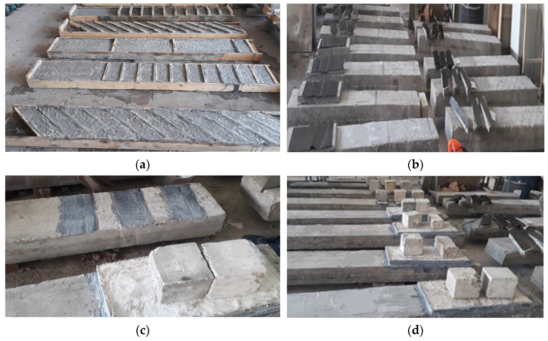
2.3. Strengthening Procedures

The RC beams were enhanced using a side-bonded method along the specified shear span. Building on the approach by Yang et al. [45], the concrete surface was mechanically ground prior to the application of the ECC or CFRP-ECC matrix, achieving a roughened depth of approximately 10 mm. Subsequent to grinding, any loose sand particles were removed, and the abraded surface was saturated with water a day ahead of layering the strengthening materials. The installation process adopted in this study unfolded in stages: As depicted in Figure 2a, formworks were crafted based on the dimensions of the strengthening scheme. Within these formworks, the ECC matrix was poured to produce a prefabricated composite plate. After a 24 h interval, these plates were de-molded and underwent a 28-day curing period in a standard laboratory setting. The prefabricated plates and the shear-critical span of the beams were subsequently roughened via mechanical grinding. Both these surfaces were primed a day in advance, as seen in Figure 2b. Prefabricated plates and carbon fiber sheets were affixed to both sides of each beam’s test span using an epoxy adhesive, as illustrated in Figure 2c. As a final step, additional weights were set on the prefabricated composite plates. This was carried out to ensure a solid bond between the concrete and the ECC plate, as represented in Figure 2d. For specimens fortified with two CFRP layers, after the first layer was applied, epoxy adhesive was spread over it. Following this, the second layer and ECC plates were embedded in place.

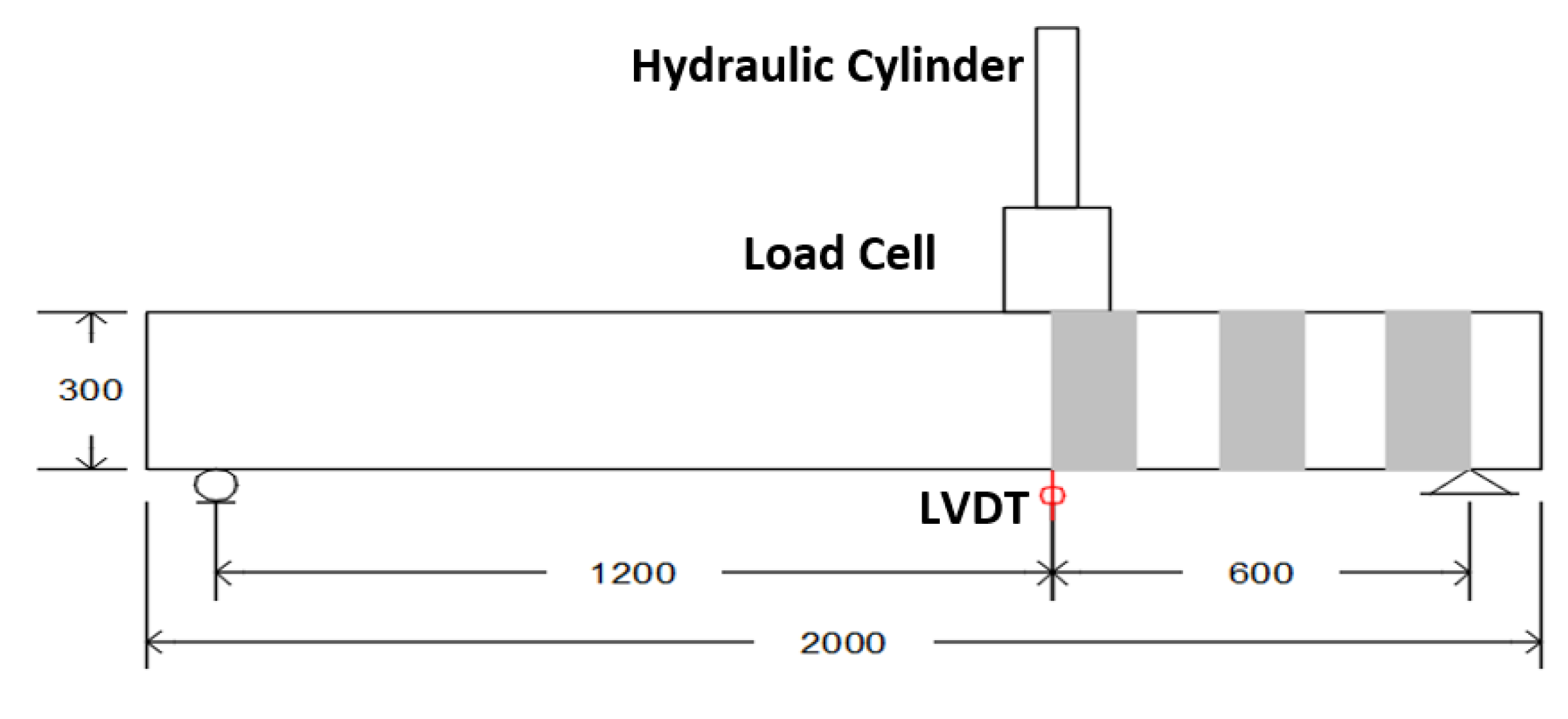
2.4. Test Setup and Instrumentation

All specimens were tested under three-point loading using a HI-TECH MAGNUS Testing Machine with a displacement-controlled rate of 0.01 mm/sec. A linear variable displacement transducer (LVDT) was installed under the loading point to monitor the beam deflection during the test, as shown in Figure 3. The loads and deflection values were recorded using a data logger.

3. Test Results and Discussion

Table 6 presents a summary of the experimental test results, including the modes of failure. For each beam, the table lists the cracking load (Pcr) with its corresponding deflection (Δcr), the yielding load (Py) with its associated deflection (Δy), the ultimate load (Pu) with its respective deflection (Δu), the ductility index (DI), and the failure mode.

3.1. Load Capacities

The tensile properties of the ECC are promising, leading to higher load values at the cracking, yielding, and ultimate stages for beams reinforced with ECC and CFRP-ECC compared to the control (un-strengthened) beam. The ultimate capacity increase ranged from 61.1% to 160.1% relative to the control beam highlighting the efficacy of the proposed shear-strengthening system. The observed results were similar to those presented by Yang et al. [45]. As delineated in Table 6, the load capacities for the two beams in group G1, with ECC layer thicknesses of 20 mm and 40 mm and saw enhancements of roughly 61% and 101%, respectively. Comparing beams E-20-F and E-40-F reveals that doubling the ECC thickness augments the ultimate capacity by approximately 24.8%. Such observations underscore that increasing the ECC layer thickness not only boosts the shear capacity but also shifts the failure mode from partial debonding to shear failure, consequently enhancing beam ductility.
Beams from group G2 (E-20-F-C-1, E-20-V-C-1, and E-20-I-C-1), which were strengthened with a single layer of CFRP and a 20 mm thick ECC layer in varying configurations, saw increases in their ultimate capacities by roughly 105.8%, 76.31%, and 96.9% for full wrapping, vertical strips, and inclined strips, respectively. When set against beams reinforced using vertical and inclined CFRP-ECC strips, the specimen with the full wrapping method demonstrated a notably superior capacity. Furthermore, beams employing inclined CFRP-ECC strips showed greater capacities compared to those with vertical CFRP-ECC strips. A comparison between beams E-20-F and E-20-F-C-1 indicates that the inclusion of the CFRP layer boosted the beam’s capacity by approximately 27.8%.
For beams in group G3, strengthened with a single 40 mm thick layer of CFRP-ECC in various configurations, the ultimate load capacities rose by 142.9%, 88.83%, and 142.1% for full wrapping, vertical strips, and inclined strips, respectively. Echoing observations from group G2, the 45°-inclined CFRP-ECC strips outperformed the vertical configuration in terms of load-carrying capacities. Compared to group G2, beams in group G3 exhibited significant gains in capacity across all strengthening configurations, with an average increase of about 16.4%. Notably, the ultimate capacities of E-40-F-C-1 and E-40-I-C-1 were virtually identical, as both beams shifted their failure mode to flexural rather than shear. This highlights that CFRP-ECC strengthening not only augmented beam capacity but also transitioned the failure mode from a sudden shear failure to a more ductile flexural failure. Lastly, a side-by-side look at E-40-F and E-40-F-C-1 reveals that the inclusion of the CFRP layer enhanced shear capacity by approximately 20.8%.
Beams in group G4 saw an uplift in shear strength by about 130.1%, 93.15%, and 142.7% for full wrapping, vertical strips, and inclined strips, respectively. Additionally, beams reinforced with 45°-inclined CFRP-ECC strips showcased superior load-carrying capacities compared to those using vertical strips. When juxtaposed with the beams of group G2, those in group G4 demonstrated a marked enhancement in shear capacity across all strengthening configurations, attributable to the employment of two CFRP layers, which amplified the capacity by roughly 15%. Conclusively, beams in group G5, reinforced with dual CFRP layers and a 40 mm thick ECC layer in varied configurations, saw their load capacities rise by 145.1%, 113.3%, and 160.1% for full wrapping, vertical strips, and inclined strips, respectively. As observed in prior groups, beams with inclined strips demonstrated higher load-carrying capacities than those with vertical strips. Notably, beam E-40-I-C-2 surpassed beam E-40-F-C-2 in capacity despite similarities in their failure modes. This disparity can be attributed to the flexural failure directly beneath the load in the fully strengthened beam. In contrast, for the beam with inclined interruptions, the flexural failure migrated to the strengthening zone.
A comparison between beams in groups G3 and G5 reveals that the number of CFRP layers contributed to an average boost in shear capacity by 6.6%. Interestingly, this uptick was less pronounced than that observed between groups G2 and G4, suggesting that the influence of the number of CFRP layers and ECC thickness on the beams’ shear capacity was relatively modest. In summary, all RC beams strengthened with either ECC or CFRP-ECC composites exhibited a notable surge in shear load-carrying capacities compared to the un-strengthened beam.

3.2. Load–Deflection Relationships

Figure 4 illustrates the load–deflection relationships of the tested beams. The strengthened beams exhibited notably greater ultimate deflections compared to the control beam. As depicted in Figure 4a, the control specimen displayed a linear response up to the point of reaching its peak load, whereas the strengthened specimens exhibited a linear response until the appearance of cracks. The control specimen achieved its peak load at a deflection of 3.76 mm, marked by a subsequent drop in load due to the formation of the principal shear crack. Specimens E-20-F and E-40-F reached their peak loads at deflection values of 5.4 mm and 6.3 mm, respectively. Notably, these samples within group G1 demonstrated an initial stiffness similar to that of the reference beam. The beams reinforced with 20 mm and 40 mm ECC layers experienced a respective increase in their ultimate deflections by 43.6% and 67.6%. The augmentation of ECC layer thickness led to concurrent boosts in both peak load and associated displacement, with rates of approximately 24.8% and 16.7%, respectively. These improvements can be attributed to the pervasive micro-cracking and strain-hardening characteristics inherent in the ECC layer. Notably, for beams in groups G2 and G3, all specimens exhibited comparable trends in their load-deflection relationships, as illustrated in Figure 4b,c. All specimens within these groups displayed a linear response until the initiation of shear cracks, marked by a subsequent change in the slope of the deflection response. This phenomenon was conspicuous in the un-strengthened specimen and less pronounced in the strengthened ones, showcasing a quasilinear response post-cracking. The comprehensive strengthening approach demonstrated peak values in both ultimate load and corresponding deflection, contrasting with the minimal values observed in the vertical strip configuration. Notably, the transition from full wrapping to inclined strips showed minimal variance, emphasizing the efficacy of the latter configuration. Furthermore, doubling the ECC layer thickness (contrasting group G3 with group G2) resulted in approximately 18%, 23%, and 7% improvements in ultimate loads, accompanied by corresponding increases in ultimate deflection of around 70.9%, 69.3%, and 4% for full wrapping, inclined strip, and vertical strip specimens, respectively, as detailed in Table 6. The stiffness of the control and E-40-F-C-1 specimens was nearly indistinguishable, whereas specimen E-40-I-C-1 exhibited superior stiffness, followed by specimen E-40-V-C-1.
Specimens E-20-F-C-2, E-20-V-C-2, and E-20-I-C-2 reached their peak loads at deflection values of 7.73 mm, 6.91 mm, and 8.7 mm, respectively. Upon evaluating stiffness, specimens E-20-V-C-2 and E-20-I-C-2 exhibited nearly identical stiffness levels, both surpassing that of the reference beam. Remarkably, the specimen with complete wrapping achieved the highest stiffness value among all tested specimens. Comparable behaviors were observed in the beams of groups G4 and G5, reinforced with two CFRP layers and ECC in different configurations (refer to Figure 4d,e). Nevertheless, specimens in group G5, featuring a 40 mm ECC layer, demonstrated elevated values in both ultimate loads and corresponding deflections compared to specimens in group G4, with a 20 mm ECC layer. The increase in ECC layer thickness (G5 versus G4) resulted in a rise of Pu by approximately 6.5%, 7.2%, and 10.4% for specimens employing full wrapping, inclined strips, and vertical strips, respectively, as detailed in Table 6. Furthermore, an escalation in the values of Δu by 47.9% and 59.4% was observed for specimens utilizing full wrapping and inclined strips, respectively, while a reduction of about 21.7% was noted for specimens employing the vertical strip strengthening configuration. Specimens E-40-F-C-2, E-40-V-C-2, and E-40-I-C-2 reached their maximum loads at deflections of 11.43 mm, 5.41 mm, and 13.87 mm, respectively. Notably, all three reinforced specimens—E-40-F-C-2, E-40-V-C-2, and E-40-I-C-2—exhibited nearly identical stiffness, surpassing that of the reference beam.

3.3. Modes of Failure

Figure 5 depicts the various failure modes observed in the tested specimens. In general, the details of the strengthening configuration limited the shape of cracks as the vertical cracks occurred due to the efficiency of the bond between the beam and the strengthening layers. Moreover, most vertical cracks occurred in the flexural failure specimens (E-40-F-C-1 and E-40-F-C-2), whereas the inclined cracks occurred due to the increase in the flexural-shear stresses. The control beam displayed the conventional shear failure mode along its critical shear span, as illustrated in Figure 5a. Here, the predominant crack initiated just beneath the loading point and extended towards the support point at an inclination of approximately 45 degrees. For the beams in group G1, both specimens, E-20-F and E-40-F, exhibited partial debonding of the ECC layer in both the longitudinal and vertical directions directly below the loading point, as indicated in Figure 5b. Beam E-40-F additionally presented micro-cracks within the ECC layer, as highlighted in Figure 5c. Furthermore, there was evident debonding between the ECC layers and the concrete substrate. The same attitude was confirmed by Wang et al. [44] when studying the shear behavior of RC beams strengthened with ECC layers.
In the second group, specimen E-20-F-C-1 exhibited the interfacial debonding of the ECC layer where a significant shear crack was evident, as illustrated in Figure 5d. This debonding was attributed to cracks in the concrete cover. For specimens E-20-V-C-1 and E-20-I-C-1, vertical cracks originated from the shear span’s base and extended upwards across the beam’s height, as highlighted in Figure 5e. The presence of inclined ECC strips in specimen E-20-I-C-1 hindered crack propagation, delaying the failure, as depicted in Figure 5f. For the third group, beam E-40-F-C-1 displayed the evolution of multiple flexural cracks within its bending span, culminating in a significant flexural crack directly beneath the loading point, as shown in Figure 5g. Notably, major shear cracks formed between the first and second strengthened strips in beams E-40-V-C-1 and E-20-V-C-1. Additionally, partial debonding of the central strip was observed at the beam’s base in a longitudinal direction, as represented in Figure 5h. Beam E-40-I-C-1 showed partial debonding on the initial strip adjacent to the loading point, flexural cracks across the mid-span, and a predominant flexural crack at the start of the second inclined strip right at the loading site, as portrayed in Figure 5i.
Specimen E-20-F-C-2, reinforced with double layers of CFRP, demonstrated similar failure patterns to specimen E-20-F-C-1, which had a single layer. This was evident from the partial debonding of the ECC layer, as depicted in Figure 5j. Further, a significant diagonal crack in the concrete formed beneath the CFRP-ECC composite and became conspicuous following the detachment of the composite. In the case of beam E-20-V-C-2, interfacial debonding was noted for the central vertical strip, and a prominent shear crack was identified between the first and last vertical strips, as highlighted in Figure 5k. Beam E-20-I-C-2 exhibited partial debonding on the first strip near the top loading point and, ultimately, a major flexural crack at the outset of the second inclined strip directly at the loading site, as portrayed in Figure 5l. In the final group, Beam E-40-F-C-2 exhibited a pronounced flexural crack directly below the loading point, as depicted in Figure 5m. Mirroring the behavior of E-20-V-C-2, beam E-40-V-C-2 displayed an interfacial debonding of the central vertical strip from the concrete and a significant shear crack spanning between the first and last vertical strips, as illustrated in Figure 5n. Beam E-40-I-C-2 presented a flexural failure characterized by concrete crushing beneath the load, accompanied by flexural cracks immediately under the loading site, as highlighted in Figure 5o.

3.4. Ductility

To evaluate the ductility characteristics of the tested beams, the ductility index (DI) was calculated, with results presented in Table 6 and shown in Figure 6. This index is defined as the ratio of the deflection at the ultimate load (Δu) to the deflection at the yielding load (Δy) [50]. Within the first group, the DI values for beams E-20-F and E-40-F rose by roughly 10% and 16.4%, respectively, compared to the control beam. This indicates that the introduction of ECC layers of varying thicknesses enhanced the specimens’ ductile performance. In the second group of beams, the enhancements in ductility were observed to be 11.8%, 10%, and 21% for the full wrapping, vertical strip, and inclined strip configurations, respectively. Among these beams, the inclined strengthening configuration demonstrated the most pronounced ductile behavior.
For group G3, the increases in the DI were 85.4%, 14.5%, and 133.6% for the full wrapping, vertical, and inclined strip configurations, respectively. This group of beams established more ductile behavior in comparison to the second group of beams. Moreover, the highest ductile behavior occurred also for the inclined strengthening configuration. For the fourth group of beams (G4), the enhancements in the DI of beams E-20-F-C-2, E-20-V-C-2, and E-20-I-C-2 were 30.9%, 27.3%, and 37.3%, respectively. Compared to group G2, the beams of this group established more ductile behavior by an average value of 15.4%. For the last group of beams, the improvements in the DI were 125.4%, 30.9%, and 170.9%, respectively. In conclusion, the strengthened specimens attained DI values larger than that of the control one, establishing that the strengthening plates efficiently achieved more ductile behavior and delayed the brittle shear failure.

4. Theoretical Code Formulation

In this paper, the theoretical shear strength was explored using two methods, according to ACI 549 [24] and ACI 440.2R-17 [51].

4.1. According to ACI 549

The nominal shear strength (Vn) of the strengthened beams is obtained as follows:
Vn = Vc + VFRCM
where Vc and VFRCM are the amount of shear strengths provided by concrete and the strengthening layers, respectively. Vc is determined experimentally as the reaction at the support of the tested beams [52].
V c = P u   L L cr L
where L is the free span among the supports, and Lcr is the shear critical span. The involvement of the strengthening layer to the shear strength (VFRCM) is expected by adding the contributions from the fiber sheets (Vf) to the related ECC (VECC) as follows:
VFRCM = F (VECC + Vf)
where F is the ratio of the strengthened area to the critical-shear area and equals 1.0 for the full wrap strengthening arrangement. This ratio is calculated as follows:
F = Strengthening   Area Critical   shear   Area
The values of F are 0.6 and 0.527 for the vertical and inclined strengthening configurations, respectively. The ECC’s contribution is calculated based on ACI 318 provisions [53] via Equation (5):
V ECC = 2   ( 0.17 f cm t m d f )
where fcm, tm, and df are the ECC compressive strength (in MPa), the thickness of the ECC strips (in mm) taken as 20 mm and 40 mm for the beam specimens, and the effective depth of the ECC-CFRP shear reinforcement (269 mm for the current study), respectively. To determine the contribution of the CFRP and ECC-CFRP composite to the shear strength (Vf), the equivalent shear-effective area of the CFRP is calculated according to Equation (6).
Afv = Af,wrap (sinαwrap + cosαwrap) + Af,weft (sinαweft + cosαweft)
where Af,warp, Af,weft, αwarp, and αweft are the area and the orientation angle for the textile in the warp and weft directions, respectively. So, the contribution of the CFRP and ECC-CFRP composite to the shear strength (Vf) is calculated as follows:
Vf = 2n Afv σfv df
where n, σfv, and εfv are the number of fabric plies placed in the composite (1 or 2) for the beams of this study, the tensile strength, and the tensile strain of the composite, respectively. According to ACI 549 [24], the effective tensile stress is expressed in terms of the effective tensile strain (εfv) and the cracked tensile elastic modulus (Ef), as shown in Equation (8):
σfv = Ef εfv
According to ACI 549 provisions [24], the effective tensile strain (εfv) is considered as 0.004. Finally, the theoretical-predicted ultimate load of the specimens ( P u Th ) can be calculated as shown in Equation (9):
P u Th   = V n   L L L cr

4.2. According to ACI 440.2R-17

According to the ACI 440.2R provisions [51], the different types of shear-strengthening schemes of RC beams using FRP composites are shown in Figure 7.
According to ACI 440 provisions [51], the nominal shear strength of the RC beams strengthened with FRP (Vn) can be determined by adding the shear strength of the externally bonded fabrics (Vf) to the concrete (Vc), and the ECC composite (VECC), according to ACI 318M −19 provisions [53].
φVn = φ (Vc +FVECC + ψfVf)
where φ is the reduction factor of the shear strength (taken as 0.75), and ψf is another reduction factor for the FRP fabrics’ shear strength (taken as 0.85). The values of Vc, F, and VECC are calculated as previously mentioned (Equations (2)–(4)). According to ACI 440.2R-17 [51], the FRP composites are employed as interrupted strips in different patterns or used as full strips along the studied span of the beam. For more details, Figure 8 explains the variables used in the calculation of the FRP fabrics’ shear strength. According to ACI 440 [51], the shear strength of FRP fabrics (Vf) is given as follows:
V f = A fv f fe × sin α + cos α × d fv s f
 
Afv = 2 n tf Wf
According to Equation (12), Afv represents the area of FRP shear reinforcement; n, tf, wf are the number, the thickness, and the breadth of the FRP sheets. The inclination angle of FRP fabric to the longitudinal axis of the beam is α, dfv represents the effective depth of the FRP fabric, sf represents the spacing between FRP strips center to center, as shown in Figure 8, and ffe represents the tensile stress for the FRP fabric. This stress can be considered from Hook’s law via Equation (13):
ffe = εfe Ef
where Ef represents the tensile elastic modulus of FRP. The strengthening and wrapping configuration affect the εfe value. The εfe value is considered using the bond-reduction constant kv for U-wraps or side-bonded wraps.
εfe = kv εfu ≤ 0.004
k v = k 1 k 2   L e 11900   ε fu 0.75
The length over which all the bond stress is sustained is known as the effective bond length (Le), and is given in the following equation:
L e = 23300   n   t f   E f 0.58
According to ACI 440 [51], the bond-reduction factor kv depends on the compressive strength of concrete, the number of FRP fabrics, and the thickness of FRP fabric (fc, n, and tf). Finally, k1 and k2 are two modification factors and are calculated using the subsequent equations:
k 1 = ( f c 27 ) 2 / 3
k 2 = d fv   L e d fv   For   ( U     wraps ) = d fv 2 L e d fv                               For   ( two   sides )
Table 7 summarizes the values of the experimental and theoretical shear strength for the tested beam specimens and good agreement was obtained. Group G5 specimens exhibited superior results in comparison to those in other groups. This notable improvement can be attributed to the reinforcing configuration, consisting of two layers of CFRP and one layer of ECC, each with a 40 mm thickness. This particular configuration outperformed the alternatives in other specimens, consequently contributing to the enhanced performance observed in Group G5. Beam E-40-I-C-2 exhibited superior resistance to shear stresses, owing to the effectiveness of the reinforcement technique and the inclined arrangement of the strengthening layers. This configuration and the provided layers of fiber enhanced the structural integrity of the beam. Moreover, the mode of failure transitioned from undesired brittle failure to desired ductile one.

5. Conclusions

This study evaluated the performance of RC beams enhanced in shear using ECC and CFRP. The experimental study encompassed fifteen RC beams. This set included one control specimen and fourteen beams fortified in shear with EB composites. Two of these specimens were enhanced with ECC layers, while the remaining were augmented with combined CFRP-ECC layers. Variables in the test included ECC layer thickness, matrix type, number of CFRP layers, and strengthening configurations such as full wrapping, vertical strips, and inclined strips. Based on the experimental program and theoretical-predicted code results, the following conclusions can be drawn:
  • The CFRP-ECC composites improved the shear capacity of the RC beams with a value ranging from 61.1% to 160.1% compared to the reference specimen.
  • The deformation of the strengthened beams was 2.31 times that of the control beam, which demonstrates the higher ductile performance of these beams.
  • The common type of failure mode for the strengthened beams was debonding or partial debonding of the strengthening layers ended with shear or flexural cracks. However, for reference one, a clear shear crack failure occurred.
  • The fully strengthened configuration for beams in groups G2 and G3 showed more improvements in terms of load capacity with respect to the vertical or inclined schemes. However, the inclined scheme showed the highest values for beams of groups G4 and G5.
  • Theoretical analysis using the two code provisions (ACI 549 and ACI 440.2R-17) was recommended to calculate the ultimate load capacity for the tested beams.

Author Contributions

Conceptualization, M.E. and H.A.S.; Data curation, M.A.S. and A.E.-Z.; Formal analysis, H.A.M.; Investigation, M.E. and M.A.S.; Methodology, M.A.S.; Resources, A.E.-Z.; Software, A.E.-Z.; Supervision, M.E., H.A.M., and H.A.S.; Validation, M.A.S.; Visualization, H.A.M. and H.A.S.; Writing—original draft, M.A.S.; Writing—review and editing, M.E. and A.E.-Z. All authors have read and agreed to the published version of the manuscript.

Funding

This research received no external funding.

Data Availability Statement

The data presented in this study are available upon request from the corresponding author.

Conflicts of Interest

The authors declare no conflict of interest.

References

  1. Jahani, Y.; Baena, M.; Gómez, J.; Barris, C.; Torres, L. Experimental study of the effect of high service temperature on the flexural performance of near-surface mounted (NSM) carbon fiber-reinforced polymer (CFRP)-strengthened concrete beams. Polymers 2021, 13, 920. [Google Scholar] [CrossRef] [PubMed]
  2. Guo, R.; Ren, Y.; Li, M.; Hu, P.; Du, M.; Zhang, R. Experimental study on flexural shear strengthening effect on low-strength RC beams by using FRP grid and ECC. Eng. Struct. 2021, 227, 111434. [Google Scholar] [CrossRef]
  3. Tahmouresi, B.; Momeninejad, K.; Mohseni, E. Flexural response of FRP-strengthened lightweight RC beams: Hybrid bond efficiency of L-shape ribbed bars and NSM technique. Arch. Civ. Mech. Eng. 2022, 22, 95. [Google Scholar] [CrossRef]
  4. Gao, W.; Dai, J.-G.; Teng, J. Three-level fire resistance design of FRP-strengthened RC beams. J. Compos. Constr. 2018, 22, 05018001. [Google Scholar] [CrossRef]
  5. Dai, J.-G.; Yokota, H.; Iwanami, M.; Kato, E. Experimental investigation of the influence of moisture on the bond behavior of FRP to concrete interfaces. J. Compos. Constr. 2010, 14, 834–844. [Google Scholar] [CrossRef]
  6. Zeng, J.-J.; Gao, W.-Y.; Duan, Z.-J.; Bai, Y.-L.; Guo, Y.-C.; Ouyang, L.-J. Axial compressive behavior of polyethylene terephthalate/carbon FRP-confined seawater sea-sand concrete in circular columns. Constr. Build. Mater. 2020, 234, 117383. [Google Scholar] [CrossRef]
  7. Bournas, D.A.; Pavese, A.; Tizani, W. Tensile capacity of FRP anchors in connecting FRP and TRM sheets to concrete. Eng. Struct. 2015, 82, 72–81. [Google Scholar] [CrossRef]
  8. Tetta, Z.C.; Bournas, D.A. TRM vs. FRP jacketing in shear strengthening of concrete members subjected to high temperatures. Compos. Part B Eng. 2016, 106, 190–205. [Google Scholar] [CrossRef]
  9. Wang, X.; Ghiassi, B.; Oliveira, D.V.; Lam, C. Modelling the nonlinear behaviour of masonry walls strengthened with textile reinforced mortars. Eng. Struct. 2017, 134, 11–24. [Google Scholar] [CrossRef]
  10. Dong, Z.; Dai, J.; Deng, M.; Wu, Z. Experimental study on the mechanical properties of textile reinforced mortar (TRM) composites with different yarn shapes subjected to uniaxial tension. Arch. Civ. Mech. Eng. 2022, 22, 185. [Google Scholar] [CrossRef]
  11. Truong, B.; Bui, T.; Limam, A.; Larbi, A.S.; Le Nguyen, K.; Michel, M. Experimental investigations of reinforced concrete beams repaired/reinforced by TRC composites. Compos. Struct. 2017, 168, 826–839. [Google Scholar] [CrossRef]
  12. Yu, Y.-L.; Yin, S.-P.; Na, M.-W. Bending performance of TRC-strengthened RC beams with secondary load under chloride erosion. J. Cent. South Univ. 2019, 26, 196–206. [Google Scholar] [CrossRef]
  13. Si, Z.; Liu, F.; Pan, J.; Dong, H. Research on Impact Resistance of Reinforced Concrete Beams Strengthened with Carbon Fiber Reinforced Polymer Grid and Engineered Cementitious Composites. Polymers 2022, 14, 1951. [Google Scholar] [CrossRef] [PubMed]
  14. Wakjira, T.G.; Ebead, U. Hybrid NSE/EB technique for shear strengthening of reinforced concrete beams using FRCM: Experimental study. Constr. Build. Mater. 2018, 164, 164–177. [Google Scholar] [CrossRef]
  15. Ge, W.; Tang, R.; Wang, Y.; Zhang, Z.; Sun, C.; Yao, S.; Lu, W. Flexural performance of ECC-concrete composite beams strengthened with carbon fiber sheet. Results Eng. 2022, 13, 100334. [Google Scholar] [CrossRef]
  16. Bournas, D.; Triantafillou, T.; Zygouris, K.; Stavropoulos, F. Textile-reinforced mortar (TRM) versus FRP jacketing in seismic retrofitting of RC columns with continuous or lap-spliced deformed bars. J. Compos. Constr. 2009, 13, 360–371. [Google Scholar] [CrossRef]
  17. Elsanadedy, H.M.; Almusallam, T.H.; Alsayed, S.H.; Al-Salloum, Y.A. Flexural strengthening of RC beams using textile reinforced mortar–Experimental and numerical study. Compos. Struct. 2013, 97, 40–55. [Google Scholar] [CrossRef]
  18. Harajli, M.; ElKhatib, H.; San-Jose, J.T. Static and cyclic out-of-plane response of masonry walls strengthened using textile-mortar system. J. Mater. Civ. Eng. 2010, 22, 1171–1180. [Google Scholar] [CrossRef]
  19. Triantafillou, T.C.; Papanicolaou, C.G. Shear strengthening of reinforced concrete members with textile reinforced mortar (TRM) jackets. Mater. Struct. 2006, 39, 93–103. [Google Scholar] [CrossRef]
  20. Brückner, A.; Ortlepp, R.; Curbach, M. Anchoring of shear strengthening for T-beams made of textile reinforced concrete (TRC). Mater. Struct. 2008, 41, 407–418. [Google Scholar] [CrossRef]
  21. Al-Salloum, Y.A.; Elsanadedy, H.M.; Alsayed, S.H.; Iqbal, R.A. Experimental and numerical study for the shear strengthening of reinforced concrete beams using textile-reinforced mortar. J. Compos. Constr. 2012, 16, 74–90. [Google Scholar] [CrossRef]
  22. Azam, R.; Soudki, K. FRCM strengthening of shear-critical RC beams. J. Compos. Constr. 2014, 18, 04014012. [Google Scholar] [CrossRef]
  23. Tzoura, E.; Triantafillou, T. Shear strengthening of reinforced concrete T-beams under cyclic loading with TRM or FRP jackets. Mater. Struct. 2016, 49, 17–28. [Google Scholar] [CrossRef]
  24. ACI Committee. ACI 549.4 R-13: Guide to Design and Construction of Externally Bonded Fabric-Reinforced Cementitious Matrix (FRCM) Systems for Repair and Strengthening Concrete and Masonry Structures. In Proceedings of the American Concrete Institute, Phoenix, AZ, USA, 20–24 October 2013. [Google Scholar]
  25. Elsanadedy, H.M.; Abbas, H.; Almusallam, T.H.; Al-Salloum, Y.A. Organic versus inorganic matrix composites for bond-critical strengthening applications of RC structures–State-of-the-art review. Compos. Part B Eng. 2019, 174, 106947. [Google Scholar] [CrossRef]
  26. Dai, J.-G.; Munir, S.; Ding, Z. Comparative study of different cement-based inorganic pastes towards the development of FRIP strengthening technology. J. Compos. Constr. 2014, 18, A4013011. [Google Scholar] [CrossRef]
  27. Ding, Z.; Dai, J.-G.; Muner, S. Study on an improved phosphate cement binder for the development of fiber-reinforced inorganic polymer composites. Polymers 2014, 6, 2819–2831. [Google Scholar] [CrossRef]
  28. Zhang, D.; Ueda, T.; Furuuchi, H. Average crack spacing of overlay-strengthened RC beams. J. Mater. Civ. Eng. 2011, 23, 1460–1472. [Google Scholar] [CrossRef]
  29. Mansur, M.A.; Ong, K.C.G. Shear strength of ferrocement beams. Am. Concr. Inst. Struct. J. 1987, 84, 10–17. [Google Scholar]
  30. Li, V.C.; Mishra, D.K.; Naaman, A.E.; Wight, J.K.; LaFave, J.M.; Wu, H.-C.; Inada, Y. On the shear behavior of engineered cementitious composites. Adv. Cem. Based Mater. 1994, 1, 142–149. [Google Scholar] [CrossRef]
  31. Yu, K.-Q.; Yu, J.-T.; Dai, J.-G.; Lu, Z.-D.; Shah, S.P. Development of ultra-high performance engineered cementitious composites using polyethylene (PE) fibers. Constr. Build. Mater. 2018, 158, 217–227. [Google Scholar] [CrossRef]
  32. Zhang, Z.; Zhang, Q. Matrix tailoring of Engineered Cementitious Composites (ECC) with non-oil-coated, low tensile strength PVA fiber. Constr. Build. Mater. 2018, 161, 420–431. [Google Scholar] [CrossRef]
  33. Zhang, R.; Matsumoto, K.; Hirata, T.; Ishizeki, Y.; Niwa, J. Shear behavior of polypropylene fiber reinforced ECC beams with varying shear reinforcement ratios. J. JSCE 2014, 2, 39–53. [Google Scholar] [CrossRef]
  34. Emara, M.; Mohamed, H.A.; Rizk, M.S.; Hu, J.W. Behavior of ECC columns confined using steel wire mesh under axial loading. J. Build. Eng. 2021, 43, 102809. [Google Scholar] [CrossRef]
  35. Wu, Z.; Deng, M.; Tian, T.; Dong, Z.; Sun, Y.; Zhang, W. Influence of textile grid forms on tensile mechanical behaviors of carbon textile-reinforced composites with polyethylene (PE) short fibers. Arch. Civ. Mech. Eng. 2023, 23, 103. [Google Scholar] [CrossRef]
  36. Pyo, S.; El-Tawil, S. Capturing the strain hardening and softening responses of cementitious composites subjected to impact loading. Constr. Build. Mater. 2015, 81, 276–283. [Google Scholar] [CrossRef]
  37. Ranade, R.; Li, V.C.; Stults, M.D.; Heard, W.F.; Rushing, T.S. Composite Properties of High-Strength, High-Ductility Concrete. ACI Mater. J. 2013, 110, 413–422. [Google Scholar] [CrossRef]
  38. Ranade, R.; Li, V.C.; Stults, M.D.; Rushing, T.S.; Roth, J.; Heard, W.F. Micromechanics of high-strength, high-ductility concrete. ACI Mater. J. 2013, 110, 375. [Google Scholar]
  39. Yang, X.; Gao, W.-Y.; Dai, J.-G.; Lu, Z.-D.; Yu, K.-Q. Flexural strengthening of RC beams with CFRP grid-reinforced ECC matrix. Compos. Struct. 2018, 189, 9–26. [Google Scholar] [CrossRef]
  40. Ranade, R.; Li, V.C.; Heard, W.F. Tensile rate effects in high strength-high ductility concrete. Cem. Concr. Res. 2015, 68, 94–104. [Google Scholar] [CrossRef]
  41. Cheung, Y.N. Investigation of Concrete Components with a Pseudo-Ductile Layer. Ph.D. Thesis, Hong Kong University of Science and Technology, Hong Kong, China, 2004. [Google Scholar]
  42. Li, Q.; Xu, S. Experimental investigation and analysis on flexural performance of functionally graded composite beam crack-controlled by ultrahigh toughness cementitious composites. Sci. China Ser. E Technol. Sci. 2009, 52, 1648–1664. [Google Scholar] [CrossRef]
  43. Ge, W.-J.; Ashour, A.F.; Ji, X.; Cai, C.; Cao, D.-F. Flexural behavior of ECC-concrete composite beams reinforced with steel bars. Constr. Build. Mater. 2018, 159, 175–188. [Google Scholar] [CrossRef]
  44. Wang, G.; Zhu, F.; Yang, C. Experimental study on Shear behaviors of RC beams strengthened with ECC layers. In Proceedings of the IOP Conference Series: Materials Science and Engineering, Chengdu, China, 13–15 December 2019; p. 042024. [Google Scholar]
  45. Yang, X.; Gao, W.-Y.; Dai, J.-G.; Lu, Z.-D. Shear strengthening of RC beams with FRP grid-reinforced ECC matrix. Compos. Struct. 2020, 241, 112120. [Google Scholar] [CrossRef]
  46. 6892-1; Metallic Materials-Tensile Testing—Part 1: Method of Test at Room Temperature. International Organization for Standardization: Geneva, Switzerland, 2009.
  47. SikaWrap®-300 C | FRP Fabrics. Available online: https://egy.sika.com/en/construction/structural-bonding/structural-strengthening/frp-fabrics/sikawrap-300-c.html (accessed on 20 June 2022).
  48. Sikadur®-330 | FRP Fabrics. Available online: https://egy.sika.com/en/construction/structural-bonding/structural-strengthening/frp-fabrics/sikadur-330.html (accessed on 20 June 2022).
  49. ACI-ASCE Committee. Recent Approaches to Shear Design of Structural Concrete. J. Struct. Eng. 1998, 124, 1375–1417. [Google Scholar] [CrossRef]
  50. Sharaky, I.; Mohamed, H.A.; Torres, L.; Emara, M. Flexural behavior of rubberized concrete beams strengthened in shear using welded wire mesh. Compos. Struct. 2020, 247, 112485. [Google Scholar] [CrossRef]
  51. Bakis, C.; Ganjehlou, A.; Kachlakev, D.; Schupack, M.; Balaguru, P.N.; Gee, D.; Karbhari, V.; Scott, D.; Ballinger, C.; Gentry, R. Guide for the Design and Construction of Externally Bonded FRP Systems for Strengthening Concrete Structures. In Reported by ACI Committee; ACI: Farmington Hills, MI, USA, 2002; Volume 440. [Google Scholar]
  52. Younis, A.; Ebead, U.; Shrestha, K.C. Different FRCM systems for shear-strengthening of reinforced concrete beams. Constr. Build. Mater. 2017, 153, 514–526. [Google Scholar] [CrossRef]
  53. ACI Committee. Building Code Requirements for Structural Concrete (ACI 318-08) and Commentary; ACI: Farmington Hills, MI, USA, 2008. [Google Scholar]
Figure 1. Strengthening and mid-span section layouts. (All dimensions are in mm). (a) Full wrapping strengthening. (b) Vertical strip strengthening. (c) Inclined strip strengthening.
Fibers 11 00098 g001aFibers 11 00098 g001b
Figure 2. Strengthening procedures of tested beams. (a) Casting ECC plates. (b) Roughened surfaces. (c) Installation of CFRP layers. (d) Addition of weights on plates.
Fibers 11 00098 g002
Figure 3. Test setup and instrumentations (dimensions are in mm).
Fibers 11 00098 g003
Figure 4. Applied load–deflection relationship measured under the loading point. (a) Group G1. (b) Group G2. (c) Group G3. (d) Group G4. (e) Group G5.
Fibers 11 00098 g004aFibers 11 00098 g004b
Figure 5. Failure modes of the tested specimens. (a) Reference. (b) E-20-F. (c) E-40-F. (d) E-20-F-C-1. (e) E-20-V-C-1. (f) E-20-I-C-1. (g) E-40-F-C-1. (h) E-40-F-C-1. (i) E-40-F-C-1. (j) E-20-F-C-2. (k) E-20-V-C-2. (l) E-20-I-C-2. (m) E-40-F-C-2. (n) E-40-V-C-2. (o) E-40-I-C-2.
Fibers 11 00098 g005
Figure 6. The effect of strengthening systems on the ductility index.
Fibers 11 00098 g006
Figure 7. FRP composites wrapping configurations [51]. (a) Completely wrapped. (b) Three-sided “U-wrap”. (c) Two sides.
Fibers 11 00098 g007
Figure 8. Parameters of FRP composites required for calculating shear strength [51].
Fibers 11 00098 g008
Table 1. Mix proportions of the concrete and ECC (kg/m3).
MaterialCementFly AshFine AggregateCoarse AggregateWaterHRWR *PP FibersW/C
RC360----6701277151--------0.42
ECC877598--------4201216.50.48
* High range water reducer.
Table 2. Mechanical properties of ECC.
SpecimenCompressive Strength (MPa)Tensile Strength (MPa)
167.57.16
2675.57
362.55.73
Mean65.676.15
Table 3. Mechanical properties of reinforcing steel.
SteelYield Strength
Fy (MPa)
Ultimate Strength
Fu (MPa)
Ultimate/Yield StrengthModulus of Elasticity
Es (GPa)
Stirrups2994581.53196
Main reinforcement5096881.35200
Table 4. Properties of CFRP [47].
MaterialArea Density (Kg/m2)Nominal Thickness (mm)Tensile Strength (MPa)Elongation (%)Elasticity Modulus (GPa)
SikaWrap®-300 C0.3040.16740001.7%230
Table 5. Matrix of the tested beams.
GroupSpecimenECC Thickness (mm)MatrixCFRP LayersStrengthening Scheme
ControlReference----------------
G1E-20-F20ECC----Full
E-40-F40ECC----Full
G2E-20-F-C-120CFRP-ECC1Full
E-20-V-C-120CFRP-ECC1Vertical strips
E-20-I-C-120CFRP-ECC1Inclined strips
G3E-40-F-C-140CFRP-ECC1Full
E-40-V-C-140CFRP-ECC1Vertical strips
E-40-I-C-140CFRP-ECC1Inclined strips
G4E-20-F-C-220CFRP-ECC2Full
E-20-V-C-220CFRP-ECC2Vertical strips
E-20-I-C-220CFRP-ECC2Inclined strips
G5E-40-F-C-240CFRP-ECC2Full
E-40-V-C-240CFRP-ECC2Vertical strips
E-40-I-C-240CFRP-ECC2Inclined strips
Table 6. Experimental test results and modes of failure.
GroupSpecimenPcr
(kN)
Δcr
(mm)
Py
(kN)
Δy
(mm)
Pu
(kN)
Δu
(mm)
DIMode of Failure
ControlReference47.902.3665.003.4069.483.761.10Shear
G1E-20-F53.602.5196.474.46111.905.401.21P. D
E-40-F69.773.23116.004.90139.706.301.28P. D + Shear
G2E-20-F-C-162.253.09127.806.43143.007.901.23D + Shear
E-20-V-C-162.483.11112.505.21122.506.311.21P. D in strips + Shear
E-20-I-C-161.073.98105.405.97136.807.961.33P. D in strips + Shear
G3E-40-F-C-183.204.34135.006.63168.8013.502.04Flexural under the load
E-40-V-C-180.613.61112.805.20131.206.561.26P. D in strips + Shear
E-40-I-C-175.422.82127.305.24168.2013.482.57P. D in strips + Flexural
G4E-20-F-C-283.552.48139.505.37159.907.731.44P. D + Shear
E-20-V-C-270.663.04112.504.95134.206.911.40D in strips + Shear
E-20-I-C-275.973.40126.805.77168.608.701.51P. D in strips + Flexural
G5E-40-F-C-299.673.33132.804.61170.3011.432.48Flexural under the load
E-40-V-C-285.342.53122.303.76148.205.411.44D in strips + Shear
E-40-I-C-281.402.70 140.704.66180.7013.872.98C.C + P. D in strips + Flexural
Notes: Pcr: cracking load; Py: yield load; Pu: ultimate load; Δcr: cracking deflection; Δy: yield deflection; Δu: ultimate deflection; DI: the ductility index; P. D: partial debonding; D: debonding; C.C: concrete crushing.
Table 7. Experimental vs. theoretical results.
GroupSpecimenExperimental (Pu)Theoretical (Pu) ACI 549 [24]Theoretical (Pu)
ACI 440 [51]
P u / P u T h
ACI 549 [24]
P u / P u T h
ACI 440 [51]
ControlReference69.48--------------
G1E-20-F111.9091.7291.711.2201.220
E-40-F139.70113.96113.951.2261.226
G2E-20-F-C-1143.00154.965160.470.9230.891
E-20-V-C-1122.50120.80117.201.0141.045
E-20-I-C-1136.80128.32134.991.0661.013
G3E-40-F-C-1168.80177.20182.710.9530.924
E-40-V-C-1131.20134.10130.540.9781.005
E-40-I-C-1168.20140.00146.711.2001.146
G4E-20-F-C-2159.90218.20183.390.7330.872
E-20-V-C-2134.20158.70128.660.8461.043
E-20-I-C-2 168.6 175.41152.920.9611.103
G5E-40-F-C-2170.30240.40205.630.7100.828
E-40-V-C-2148.20172.00142.000.8621.044
E-40-I-C-2180.70187.14164.640.9661.098
Disclaimer/Publisher’s Note: The statements, opinions and data contained in all publications are solely those of the individual author(s) and contributor(s) and not of MDPI and/or the editor(s). MDPI and/or the editor(s) disclaim responsibility for any injury to people or property resulting from any ideas, methods, instructions or products referred to in the content.

