Reinforced Concrete Beams with Carbon-Fiber-Reinforced Polymer Bars—Experimental Study


Reinforced Concrete and Seismic Design of Structures Laboratory, Civil Engineering Department, School of Engineering, Democritus University of Thrace, Xanthi 67100, Greece
*
Author to whom correspondence should be addressed.
Fibers 2018, 6(4), 99; https://0-doi-org.brum.beds.ac.uk/10.3390/fib6040099
Submission received: 20 November 2018
/
Revised: 7 December 2018
/
Accepted: 11 December 2018
/
Published: 14 December 2018
Abstract
:Innovative reinforcement as fiber-reinforced polymer (FRP) bars has been proposed as alternative for the substitution of the traditional steel bars in reinforced concrete (RC) structures. Although the advantages of this polymer reinforcement have long been recognised, the predominantly elastic response, the reduced bond capacity under repeated load and the low ductility of RC members with FRP bars restricted its wide application in construction so far. In this work, the behavior of seven slender concrete beams reinforced with carbon-FRP bars under increasing static loading is experimentally investigated. Load capacities, deflections, pre-cracking and after-cracking stiffness, sudden local drops of strength, failure modes, and cracking propagation have been presented and commented. Special attention has been given in the bond conditions of the anchorage lengths of the tensile carbon-FRP bars. The application of local confinement conditions along the anchorage lengths of the carbon-FRP bars in some specimens seems to influence their cracking behavior. Nevertheless, more research is required in this direction. Comparisons of experimental results for carbon-FRP beams with beams reinforced with glass-FRP bars extracted from recent literature are also presented and commented. Comparisons of the experimental results with the predictions according to ACI 440.1R-15 and to CSA S806-12 are also included herein.
1. Introduction
Reinforced concrete (RC) structures have been originally designed using steel bars as reinforcement. Last decades innovative materials manufactured of glass, carbon, aramid, or basalt fibers in polymer matrix have been proposed as alternatives for the substitution of the traditional steel bars in RC structures. In general, fiber-reinforced polymers (FRPs) have already been largely applied for the strengthening of deficient RC structural members in the form of FRPs as additional external flexural or shear reinforcement. Specifically, FRP sheets, strips, laminates, rods, or ropes have been extensively applied for the repairing and strengthening of RC beam-column joints [1,2,3], columns [4], frames [5,6], beams [7,8,9,10], deep beams [11], corroded beams [12], and slabs [13].
Further applications of fiber-reinforced polymer (FRP) bars are recommended mainly in cases that the possibility of corrosion in steel RC structures may cause serious safety and financial concerns in harsh environments. As main advantages of FRP bars in comparison to the conventional steel bars can be considered the high corrosive-resistant behavior, the high tensile strength in the direction of the fibers and their lightweight non-magnetic characteristics. Due to these attractive characteristics, the application of FRP bars as internal reinforcement in RC structural members under monotonic or/and seismic loading has been examined recently [14,15,16,17,18,19].
Nevertheless, FRPs exhibit brittle behavior and are characterized from their linear-elastic stress–strain response. Therefore, FRP bars do not yield like steel reinforcing bars. Furthermore, low modulus of elasticity and low shear strength are also shortcomings from the structural engineering point of view. Consequently, concrete beams reinforced with FRP bars show linear-elastic behavior up to failure without exhibiting any yielding and their final failure is characterized as brittle whether happens due to FRP rupture or due to concrete crushing; although the latter one can be considered as more desirable for RC flexural structural elements with FRPs [20,21]. To compensate for the lack of post yielding behavior ACI 440.1R-15 [22] recommends higher margin of safety for the design of RC beams with FRP bars compared to the one for the design of beams reinforced with steel bars [23]. Specifically, for cases that the FRP rupture governs the design a strength reduction factor equal to 0.55 is recommended.
Furthermore, wider and deeper cracks coupled with the low strength and stiffness of the FRPs in the transverse direction to their axis result in a questionable contribution of the longitudinal tensional FRP bars as dowel action to the shear capacity of the concrete beams [24,25]. In general, studies revealed that the overall shear capacity of concrete beams with FRP bars is considered to be lower than that of conventionally steel RC beams since the shear resisting components of the elements with FRPs found to be lower in comparison to the ones of the elements with steel reinforcement [26,27]. However, in the study of Herwig and Motavalli [28] it has experimentally been obtained that the axial tensile resistance of glass-FRP bars was not considerably affected by the transverse force since this force did not exceed the 50% of the pure transverse force resistance. Nevertheless, lower bond characteristics between the FRP bars and the surrounding concrete have already been reported with respect to the traditional deformed steel reinforcing bars [29,30], especially under cyclic loading conditions [31].
The aforementioned disadvantages along with the high cost of the FRP bars in comparison to the steel bars are important factors that restraint the massive usage of this material only in harsh and aggressive environments. Recently, an alternative reinforcement technique has been investigated in order to enhance flexural ductility and simultaneously to retain the high strength of the FRP bars by using the hybrid combination of steel and FRP longitudinal reinforcement [32,33,34].
Commercially available FRP bars include FRP of glass fibers (G-FRP bars), carbon fibers (C-FRP bars), aramid fibers (A-FRP bars), and basalt fibers (B-FRP bars). These bars exhibit different and varying mechanical properties, physical appearance, and surface configuration and therefore apparent is that a lot of research is needed ahead.
In recent decades a lot of experimental research has been conducted for the behavior of concrete beams reinforced with G-FRP beams. It has reported that G-FRP reinforced beams experience higher deflections and larger crack widths compared to beams traditionally reinforced with steel bars [19]. This is attributed to the low elastic modulus of GFRP bars as documented in the ACI 440.1R-15 guidelines for the design and construction of concrete members and structures reinforced with FRPs [22]. Due to the low elastic modulus of G-FRP bars, beams reinforced with these bars also exhibit low post cracking flexural stiffness compared to the concrete beams conventionally reinforced with steel bars [35]. It can be concluded that significant analytical and experimental research efforts have been carried out on the behavior of G-FRP reinforced beams under various loadings [36,37,38,39,40,41,42,43].
On the other hand, the modulus of elasticity of C-FRP bars—although lower than the one of the steel bars—is three to four times higher than that of the G-FRP bars. C-FRP bars also exhibit substantially higher strength than G-FRP or A-FRP bars. Henceforth, although some research has been reported so far on the behavior of concrete beams reinforced with C-FRP bars the problem of the behavior of these beams under loading as members of RC structures is still open to question.
The behavior of these members involves the influence of phenomena such as concrete cracking and crack propagation, bond strength, the dowel action as shear contribution of the longitudinal C-FRP bars that even independently cannot be considered as well understood in the case of C-FRP reinforced beams. The current research work has been carried out to experimentally investigate the behavior of typical slender concrete beams reinforced with C-FRP bars under increasing static loading. Observed stiffness, maximum loading capacity, and deflection per loading step, development of the cracking width are presented and commented. Special attention has been given on the bond conditions of the anchorage lengths of the tensile C-FRP bars. In this direction, the potential influence of local confinement conditions along the anchorage length of the C-FRP bars applied in three specimens on the overall response of the examined beams is investigated. Further comparisons of experimental results for beams with C-FRP bars with corresponding ones for beams reinforced with G-FRP bars extracted from literature are also included herein. Finally, comparisons of the test results for the beam deflections with predictions obtained from modern Codes (ACI 440.1R-15 [22] and CSA S806-12 [44]) are also presented and commented in this study.
2. Experimental Work
The current experimental project has been carried out to investigate the behavior of flexural concrete beams reinforced with C-FRP bars under increasing static loading and gain this way insight in the development of the cracking system. The potential influence of the anchorage conditions enhancement of the C-FRP bars by applying a local confining steel spiral on the overall behavior of the beams is also studied.
2.1. Specimen Description
Seven beams were cast and experimentally tested in four-point loading. The tensile reinforcement of five beams was C-FRP bars whereas the reinforcement of the other two beams included only steel bars (specimens denoted as S10 and S12 of group “S”). RC beams with C-FRP bars are sorted in two groups (“BF5” and “BF10”). Group “BF5” includes specimens BF5-0, BF5-1, and BF5-2 whereas group “BF10” includes two specimens BF10-0 and BF10-1 (see also Table 1).
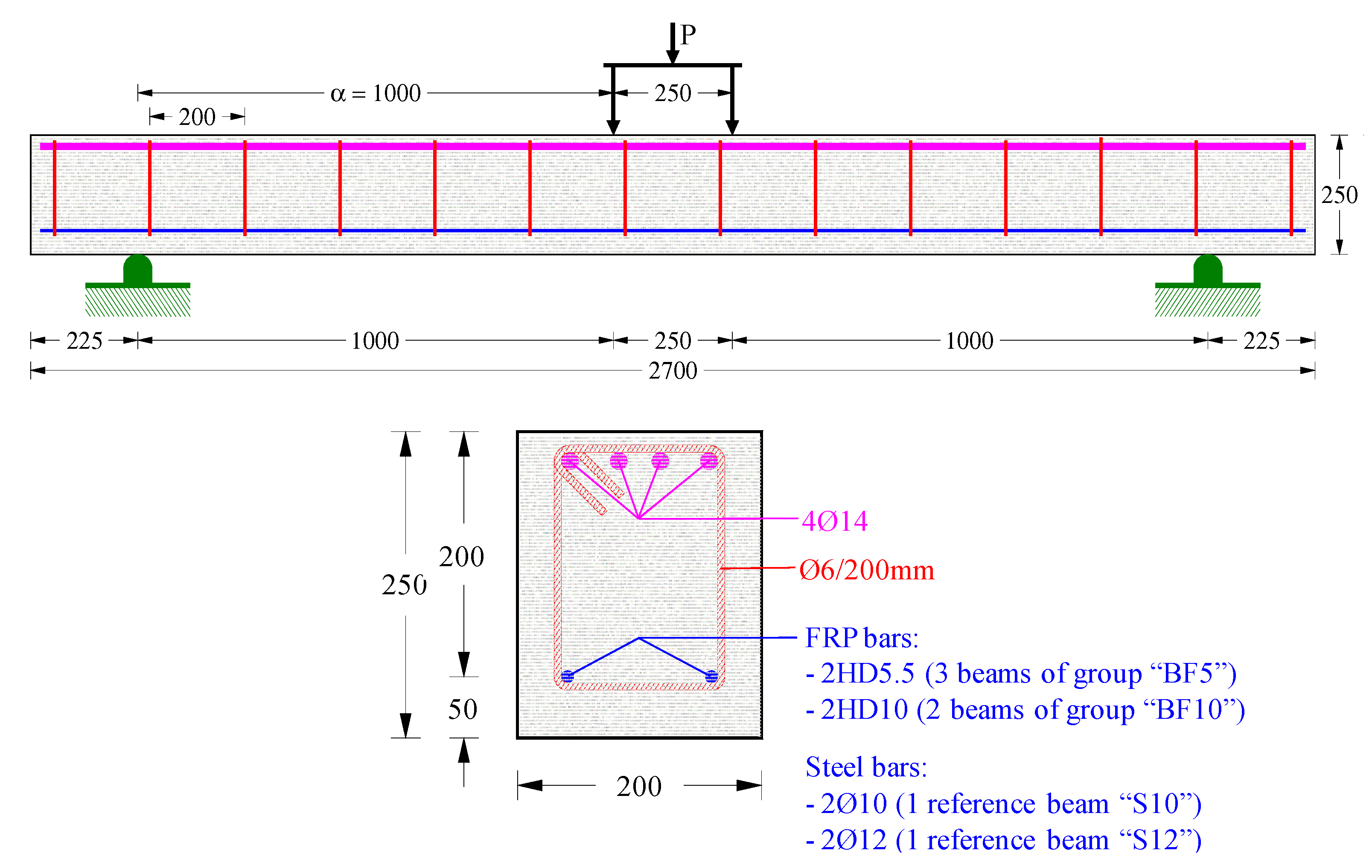
The geometry, the cross-sectional and the reinforcement details of all specimens are presented in Figure 1. Their total length is 2.7 m, the width to height ratio is b/h = 200/250 mm, the effective depth is d = 200 mm, the shear span is a = 1 m and the shear span-to-depth ratio is a/d = 5 (typical slender beams). All beams have the same dimensions, the same high compression steel reinforcement ratio in order to avoid premature failure of the compression zone of concrete and the same ratio of transverse reinforcement for comparison reasons. The compression reinforcement consists of common deformed steel bars with diameter 14 mm (4∅14 top) that corresponds to a geometrical ratio of the top longitudinal compression steel reinforcement 1.54%.
Further, the transverse shear reinforcement kept the same for all beams and includes mild steel closed stirrups with diameter 6 mm and spacing at 200 mm (∅6/200 mm) as shown in Figure 1. The geometrical ratio of the bottom longitudinal tension reinforcement of each beam is presented in Table 1.
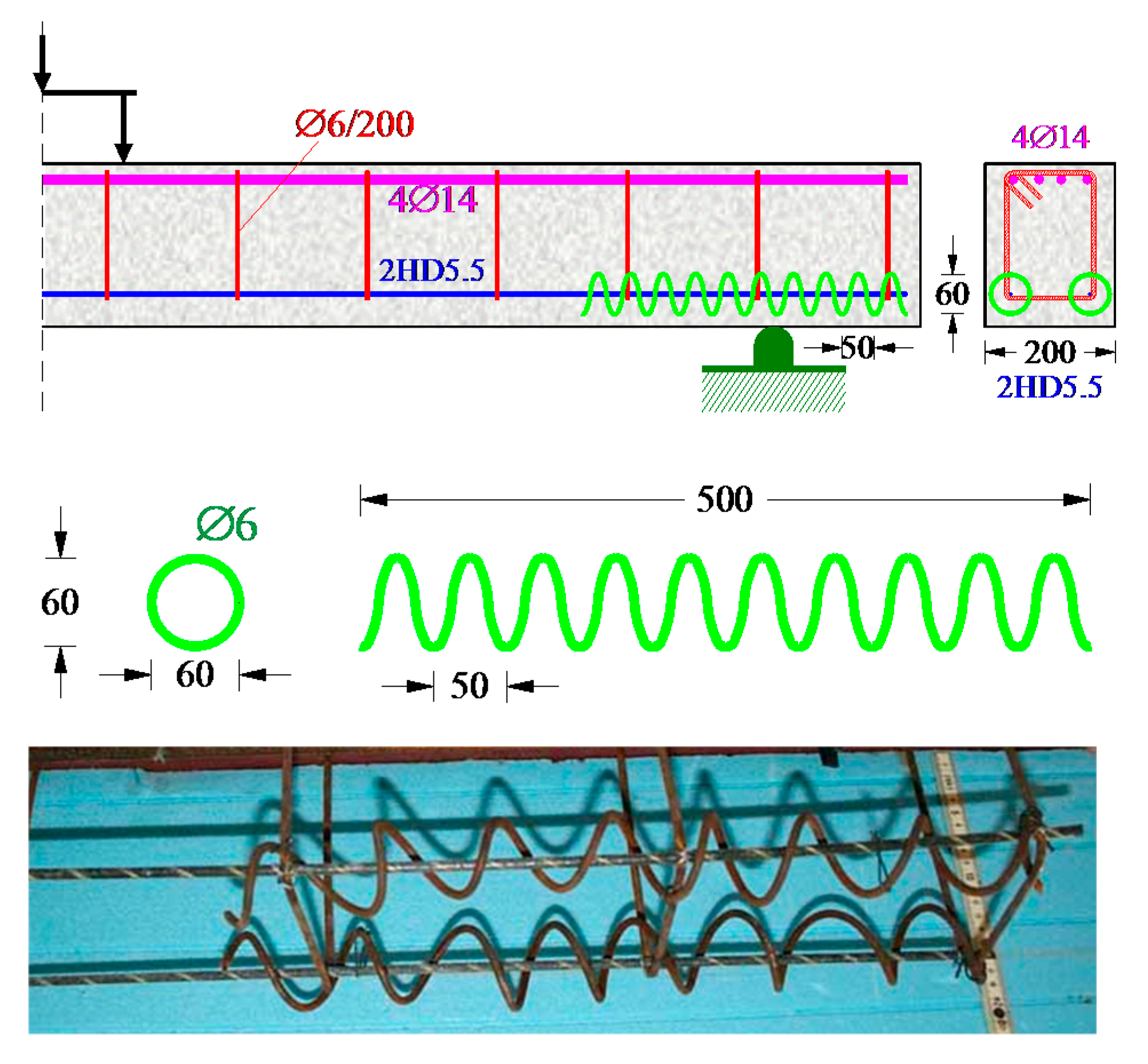
Furthermore, two beams of group “BF5” (specimens BF5-1 and BF5-2) and one beam of group “BF10” (specimen BF10-1) have an additional enhanced anchorage configuration of the tensional FRP bars. It includes a continuous mild steel spiral transverse reinforcement with circular shape placed around and at both anchorage ends of each C-FRP bar. This anchorage system is used to improve the C-FRP bar and the concrete bond properties at this area due to the developing local confinement. Special anchorage systems and new methods to prevent premature debonding of FRPs are of great importance [11,13,45]. The application length of the spirals is 500 mm for beams BF5-1 and BF10-1 and 750 mm for specimen BF5-2. The geometrical and the reinforcement characteristics of the provided spiral for BF5-1 and BF10-1 beams are shown in Figure 2.
2.2. Material Properties
The used C-FRP bars (denoted as HD5.5 and HD10) were produced by the pultrusion process of the carbon fibers according to the following specifications of the manufacturer. First, continuous carbon fibers with high tensile strength and a volume of fraction of 57% and 60% by volume for HD5.5 and HD10, respectively, were provided. The nominal tensile strength and the elastic modulus of these carbon fibers are greater than 4 GPa and 230 GPa, respectively. Afterwards, these carbon fibers have been saturated with resin in order to produce the synthetic C-FRP bar. The manufactured C-FRP bars have also a rough external surface produced by special surface treatment with quartz-sand. The nominal ultimate tensile strength and the elastic modulus of the final product, the C-FRP reinforcing bars used in this study, are ffu = 1.8 GPa and Ef = 130 GPa, respectively.
Standard 150/300 mm concrete cylinders were tested under axial compression and splitting tension at the day of the tests of the beams. The average compressive and splitting tensile strength of the used concrete for all beams are fc = 29.1 MPa and fct = 2.42 MPa, respectively. The maximum aggregate size used in the concrete mix is 16 mm. The experimentally obtained yield tensile strength, fy, of the deformed steel bars is 555 MPa for the ∅10 tension bars of the beam S10, 545 MPa for the ∅12 tension bars of the beam S12 and 550 MPa for the ∅14 compression bars, whereas the yield tensile strength of the ∅6 mild steel stirrups and spirals is 310 MPa.
2.3. Test Setup and Instrumentation
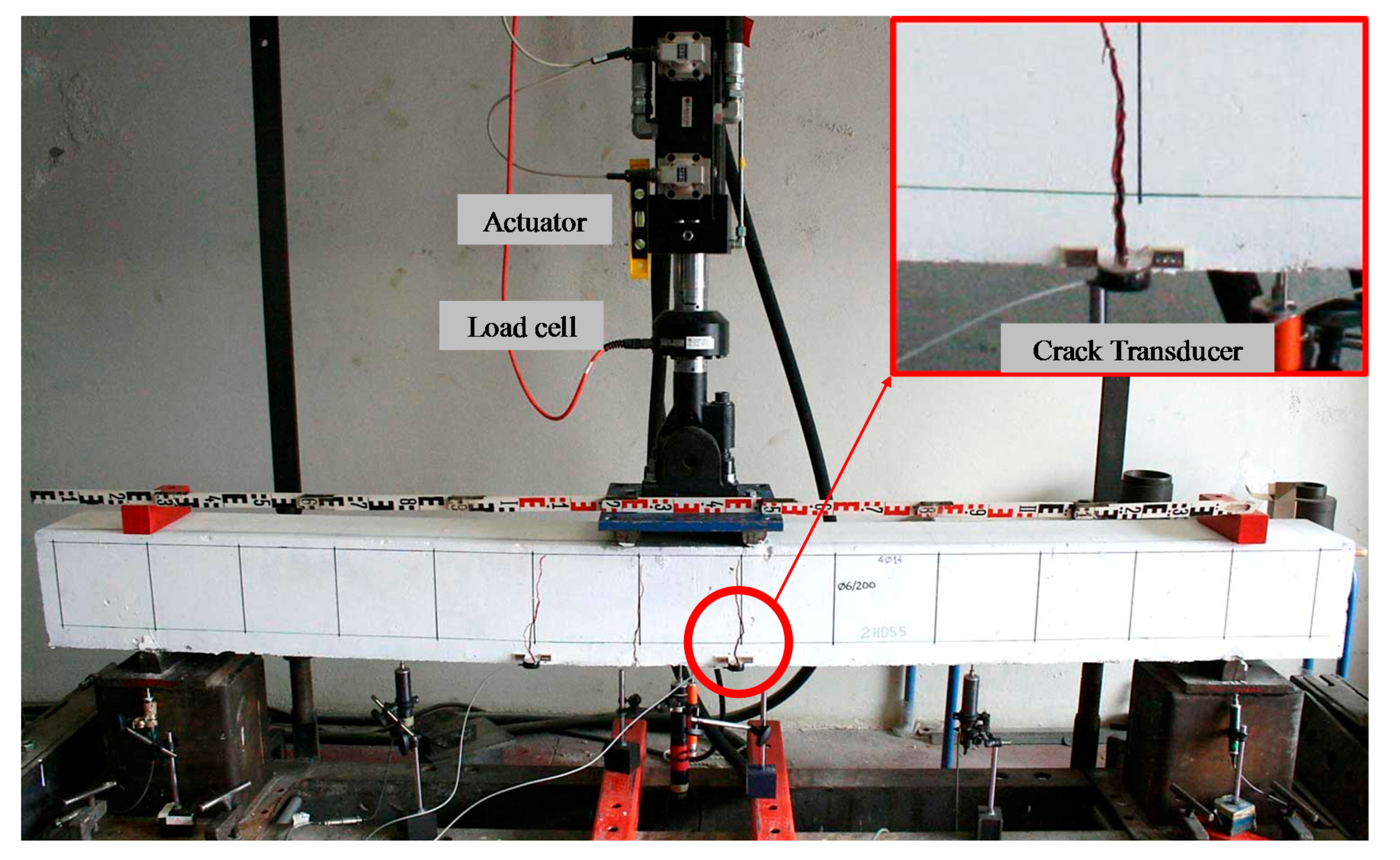
A four-point bend testing rig is used for the monotonic loading of the RC beams, as presented in Figure 3. The beam specimens were simply edge-supported on roller supports 2.25 m apart in a rigid laboratory frame. The imposed load was applied in two points 250 mm apart in the midspan of the specimens (four-point loading) and the length of each shear span of the beams is equal to 1 m (typical slender beams with shear span-to-depth ratio equal to 5).
The load was imposed by a pinned-end actuator and consistently increased with low rate. Values of the applied load were recorded by a load cell with accuracy equal to 0.05 kN. Furthermore, the deflections of the beams were measured using six linear variable differential transducers (LVDTs); four of them with 0.01 mm and two with 0.005 mm accuracy. Two of the installed LVDTs were placed at the midspan of the beams (one at the front side and one at the back side to increase accuracy), one at the middle of the left shear span, one at the middle of the left shear span and two at the supports (see also Figure 3). This way, the net deflections at the midspan and at the middle of the left-span and of the right-span of the beams were accurately estimated. Load and corresponding deflection measurements were recorded continuously during the performed tests until the failure of the beams.
3. Deflections
3.1. Deflection Curves
The load to the deflection observed curves at the middle of the span of the tested beams with C-FRP bars are presented in Figure 4, Figure 5, Figure 6, Figure 7 and Figure 8. Each curve represents the experimental behavior of the beam as it is obtained from the measurements of the load and the corresponding deformations of the LVDTs till the total failure.
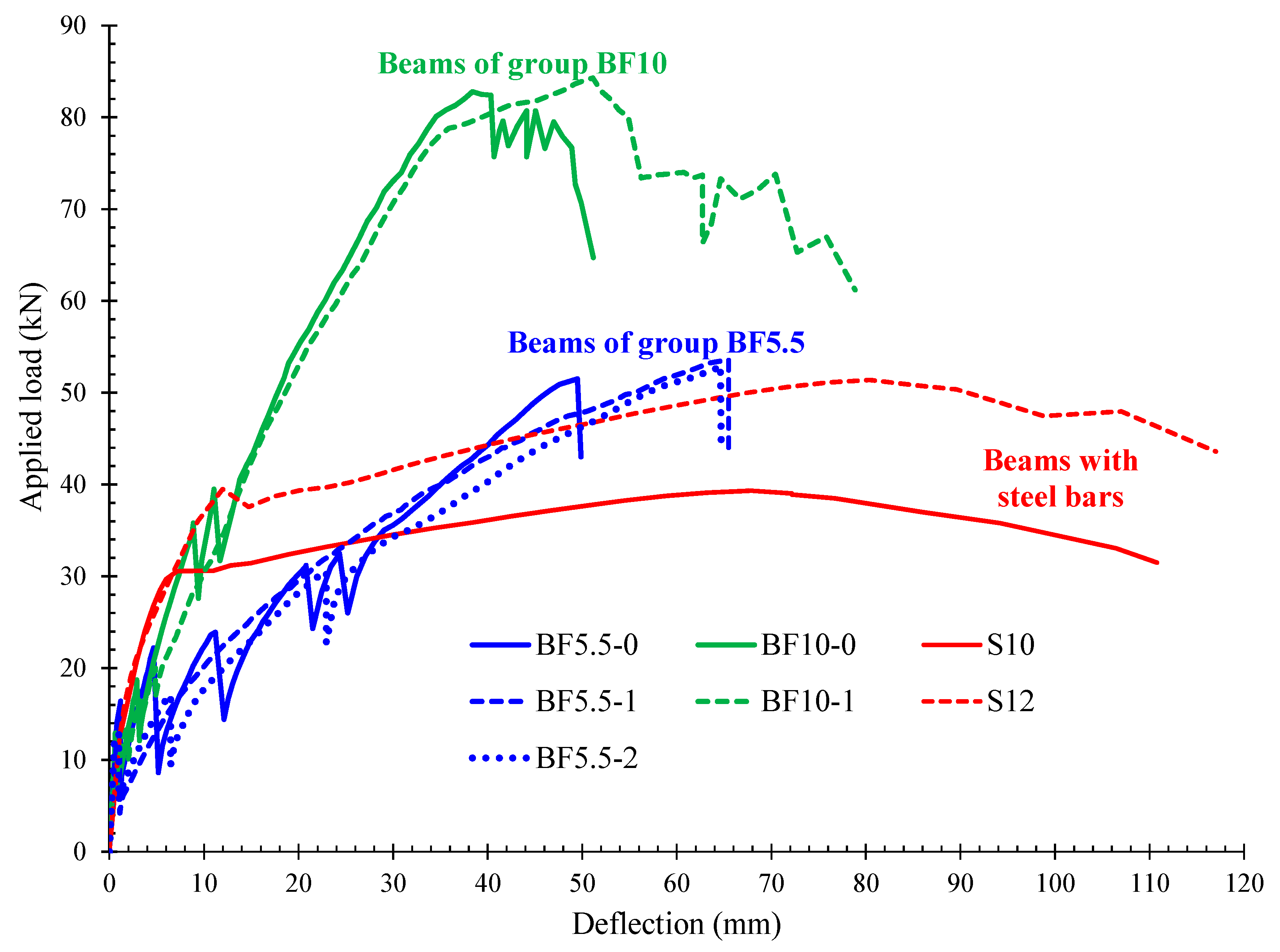
The curves include first a small pre-cracking part that exhibits high flexural stiffness. The main part of these curves though is the after-cracking part that exhibits substantially lower stiffness than the one of the uncracked first part. The observed maximum loads and the corresponding deflections at peak load bearing capacity of the beams are included in Table 1. For comparison reasons the deflection curve of all tested specimens are presented in Figure 9 where the behavior of the C-FRP reinforced beams is compared with the typical ductile behavior of the two RC beams with steel bars.
3.2. Loading Drops
As it can be observed from the load-deflection curves (Figure 4, Figure 5, Figure 6, Figure 7, Figure 8 and Figure 9), each time a crack appears in the C-FRP reinforced beams a sudden load drop is simultaneously occurred. It may be attributed to the fact that a local decrease of the stiffness undergo at the cracked section of the beam due to the formation of long flexural cracks in combination with the low elastic modulus of the C-FRP bars. The stiffness of the member was high before cracking since the whole area of the concrete cross-section was in effect. After cracking, only the part of the concrete cross-section that is under compression is in effect while the contribution of the C-FRP tensile bars is rather low due to the low value of the modulus of elasticity of this material. This phenomenon usually takes place in beams where the normalized reinforcement ratio ρf(Ef/Ec) is very low. Therefore, for the same value of beam deflection higher value of the imposed loading is obviously required when the cross-section is uncracked in comparison with the value of loading required to produce the same deflection after the cracking.
Such loading drops are not observed in the steel RC beams since in these cases the modulus of elasticity of the steel bars is substantially higher compared to the one of the C-FRP bars and the normalized reinforcement ratio ρs(Es/Ec) is rather high. Moreover, it is important to be mentioned that the development of cracking is really faster in the early stages in the case of the C-FRP reinforced beams due to the low axial stiffness of the C-FRP bars than in the case of the steel reinforced beams where the cracks develop at a lower rate and therefore no loading drops are observed when a crack appears. Based on the same point of view, beams of group “BF10” exhibited lower loading drops than the beams of group “BF5” since they have been reinforced with C-FRP bars of higher diameter and therefore with higher stiffness.
Additionally, it should be stressed that these loading drops are not observed, or at least they are fewer and lower, in the response of the beams BF5-1 and BF10-1 with local spiral confinement reinforcement (see also Figure 5, Figure 8 and Figure 9). This improvement on the flexural behavior of these specimens is attributed to the C-FRP bars anchorage conditions enhancement that improved the bond behavior between C-FRP bar and the surrounding concrete.
4. Crack Shapes and Failure Modes
4.1. “BF5” Series
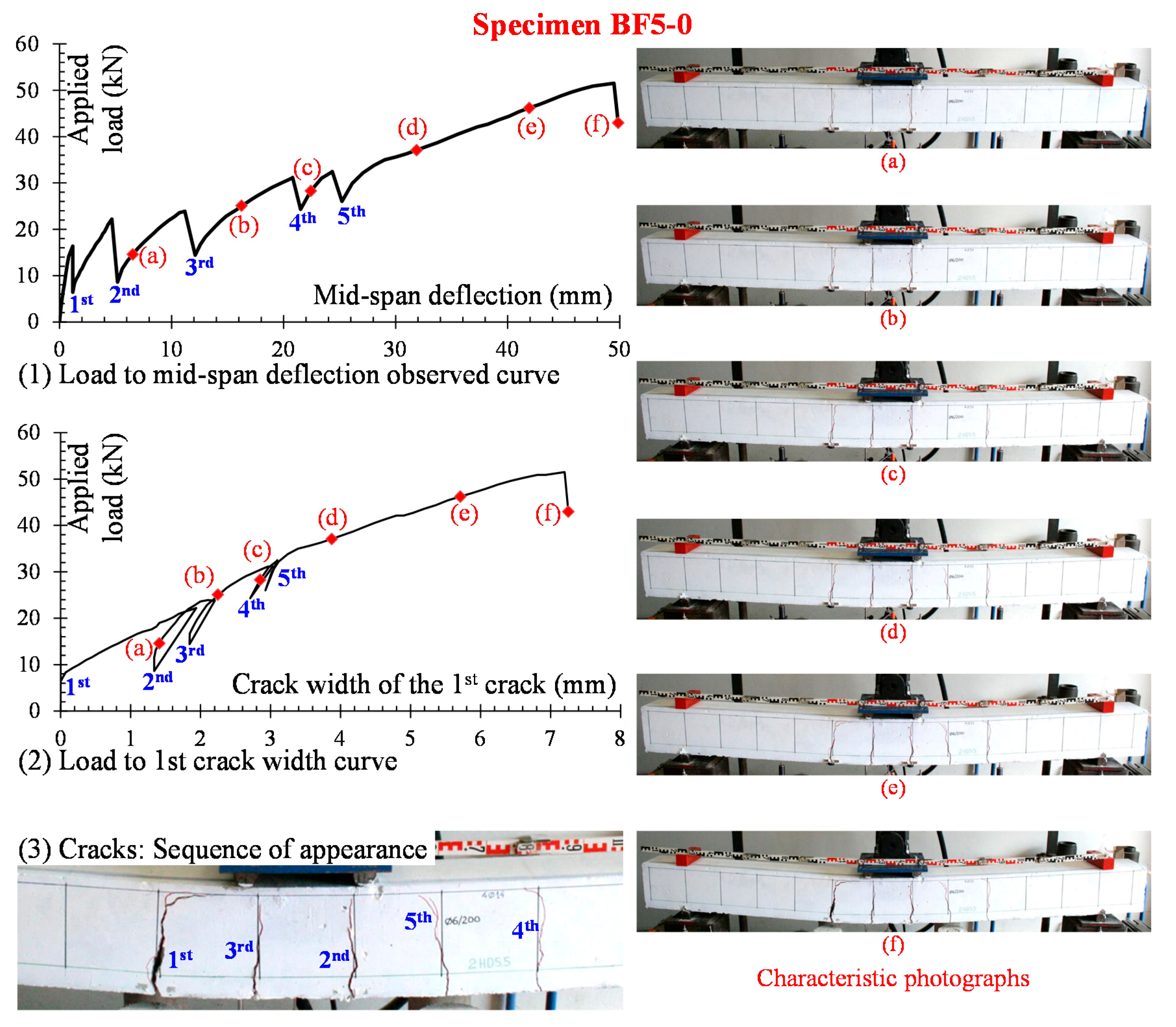
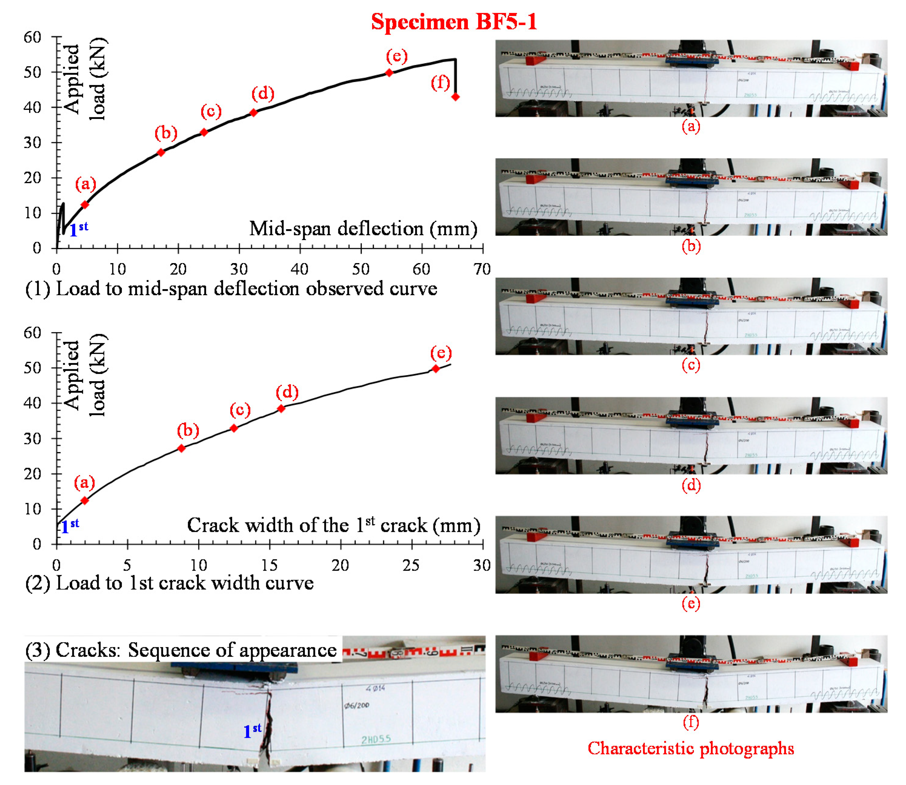
The crack shapes for series “BF5” beams are presented in Figure 4, Figure 5 and Figure 6. In general, the first cracks were typical vertical flexural cracks in the area of the tension zone within and very close to the constant bending moment area at a load of about 16 kN for beam BF5-0, 13 kN for beam BF5-1 and 13 kN for beam BF5-2. Furthermore, it is mentioned that all beams of “BF5” series exhibited flexural response and failed due to the rupture of the C-FRP bars, as shown in the photographs of Figure 4f and Figure 5f, and 6f and as denoted in Table 1 (observed failure: “F-R”).
4.1.1. Beam BF5-0
Right after the appearance of the first crack at a load almost 16 kN the load decreased suddenly down to 6.5 kN. During the loading procedure new cracks continued to form in the constant moment area while the first one propagated vertically towards the compression zone. It is noted that the formed cracks are from the beginning rather deep (Figure 4). Further small crack branches appear near the lower tension zone up to approximately 70% of the ultimate load. The formation of new cracks has not been observed at higher loading stages.
The development of the first crack width versus the applied load is presented in Figure 4. It can be observed that at some points of this diagram marked as (a), (b), and (c) the loading is temporarily substantially decreased whereas the crack width remains unchanged or is slightly decreased. In the next loading step the loading value along with the crack width come back in the previous high levels. These sudden load decreases occur at the moment that a new crack appears. This phenomenon could be attributed to the low axial stiffness of the C-FRP bar. The axial stiffness is equal to cross-section area, Af, multiplied by the modulus of elasticity, Ef. Furthermore, due to the low AfEf every new crack almost from the beginning extends vertically up to the compression zone. Simultaneously, it can be observed that the first crack grows wider. It is stressed that all the formed cracks located at the positions of the vertical stirrups.
4.1.2. Beam BF5-1
After the appearance of the first crack at a load almost 13 kN the load decreased suddenly down to 4 kN. During the loading procedure new well-formed cracks have not really been formed in this beam. Nevertheless, as the test procedure went on and the load was increased, the first crack grew wider and propagated vertically towards the compression zone. At the top of this crack and at the position of the compression longitudinal steel bars horizontal cracks appeared that could be considered as signs of concrete crash initiation.
The development of first crack width versus the applied load for specimen BF5-1 is presented in Figure 5. On the contrary to the crack width diagram of the specimen BF5-0 (see Figure 4) in this case no points of sudden load falls are observed. It is emphasized that in this case no new crack appeared.
4.1.3. Beam BF5-2
After the appearance of the first crack at a load almost 13 kN the load decreased suddenly down to 6 kN. During the loading procedure only one or two very small new cracks have formed in the beam. Nevertheless, as the loading was increasing, the first crack grew wider and propagated vertically towards the compression zone. The cracking pattern of this beam considered as similar to the one of the beam BF5-1. The development of the first crack width versus the applied load for specimen BF5-2 is presented in Figure 6. In this figure, it can be observed that at two points of this diagram the load values are temporarily decreased. In both cases, in the next loading step the load retakes the high value it had in the previous steps.
The application of the local confinement conditions along the anchorage lengths of the C-FRP bars in beams BF5-1 and BF5-2 seems to influence the development of the cracking system of these specimens. This influence appeared to be more intense in the case of the specimen BF5-1. Furthermore, specimens BF5-1 and BF5-2 with local spiral confinement reinforcement exhibited increased deflection at peak load (δpeak = 65.5 mm and 64.6 mm, respectively) with regards to the beam without spirals BF5-0 (δpeak = 49.5 mm), as shown in Table 1 and Figure 9. Nevertheless, more research is required in this direction.
4.2. “BF10” Series
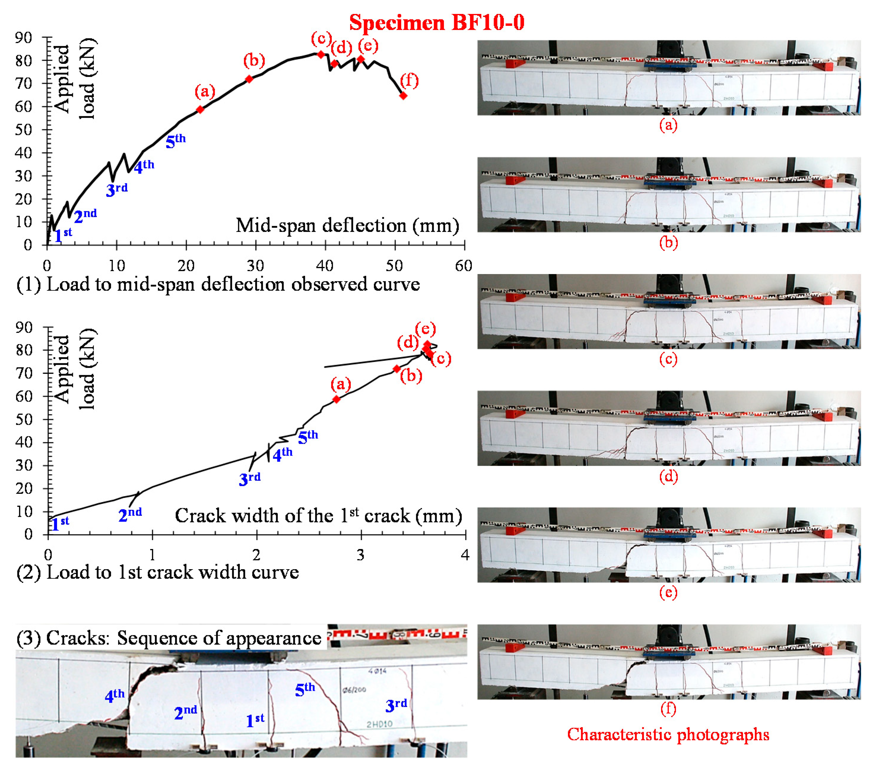
The crack shapes for the two beams BF10-0 and BF10-1 of the series “BF10” are presented in Figure 7 and Figure 8, respectively. In general, the first cracks were typical vertical flexural cracks in the area of the tensional zone, near and within the constant bending moment area in the middle part of the beams. Furthermore, it is noted that due to the high tensile strength of the C-FRP bars even a small increase of the C-FRP reinforcement (from to 2 bars of diameter 5.5mm in series “BF5” to 2 bars of diameter 10mm in series BF10) can possibly change the nature of the failure from pure flexural (series “BF5”) to a behavior with final failure of shear nature (series “BF10”). This modification and the observed shear failure mode is also attributed to the fact that the beams of “BF10” series have larger tension reinforcement ratio (0.39%) than the corresponding ratio of the beams of “BF5” series (0.12%) and, therefore, larger shear demand.
4.2.1. Beam BF10-0
The appearance of the first crack was observed at the position of the vertical stirrup close to the left part of the constant moment area at a load almost equal to 13 kN and right after the load suddenly decreased down to 6 kN. Subsequently during the next steps of the loading sequence new cracks were formed in the tension zone while the existing ones propagated towards the compression zone. Nevertheless, near the peak load the first crack close to the left end of the constant moment area developed inclined branches at its bottom end and at its top end. Another inclined crack appeared and developed similarly near the right end of the constant moment area. After the peak loading point the first crack grew wider and became a clear shear crack and subsequently a brittle shear failure occurred (see also Figure 7).
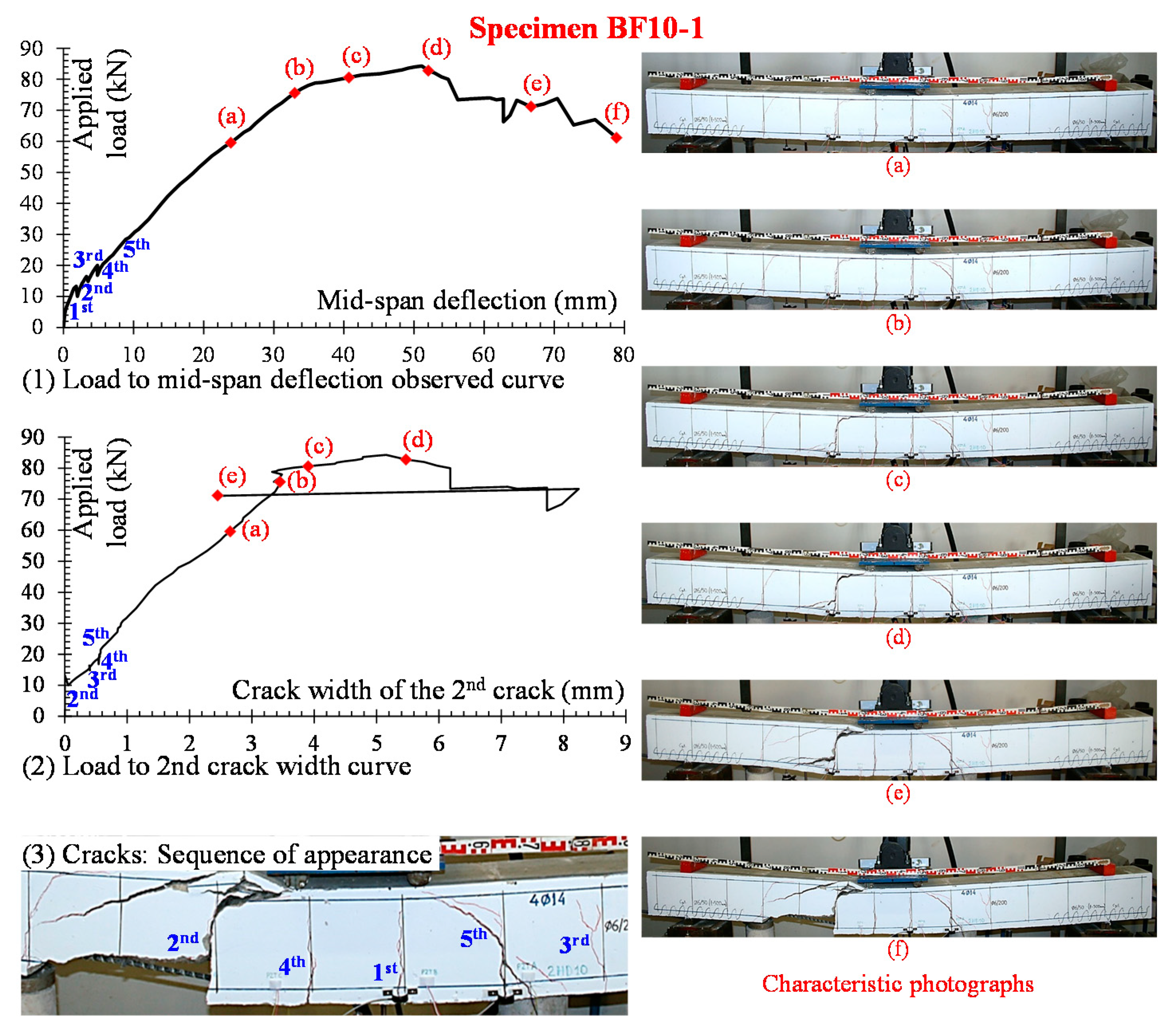
4.2.2. Beam BF10-1
Close to the left part of the constant moment area at the position of the adjacent stirrup and at a load equal to almost 13 kN took place the appearance of the first crack and right after the load suddenly decreased down to 10 kN. Subsequently, during the next steps of the loading procedure, only one new well-formed crack appeared. This crack was formed at the position of the stirrup close to the right end of the constant moment area. Near the peak loading point, both these cracks developed at their top ends and at their bottom ends horizontal crack branches. The first of them grew wider became a clear shear crack and after a while a brittle shear failure took place (see also Figure 8).
The application of the local confinement conditions along the anchorage lengths of the C-FRP bars in beam BF10-1 seems to influence the development of the cracking system and the overall behavior. Although both beams of group “BF10” failed in shear, specimen BF10-1 with local spiral confinement reinforcement exhibited increased deflection at peak load (δpeak = 51.1 mm) with regards to the beam BF10-0 without anchorage system (δpeak = 38.4 mm), as shown in Table 1 and Figure 9.
5. Comparisons of Deflections with G-FRP Reinforced Beams
Significant analytical and experimental studies have been reported so far on the behavior of Glass-FRP (G-FRP) reinforced beams under various loadings [19,36,37,38,39,40,41,42,43]. In these cases, it is important to be mentioned that the modulus of elasticity of C-FRP bars, although lower than the one of the steel bars, it is three to four times higher than that of the G-FRP bars and furthermore C-FRP bars also exhibit substantially higher strength than G-FRP. Henceforth, although some research has been reported so far on the behavior of C-FRP reinforced beams the problem of the behavior of these beams under loading as members of RC structures is still under investigation.
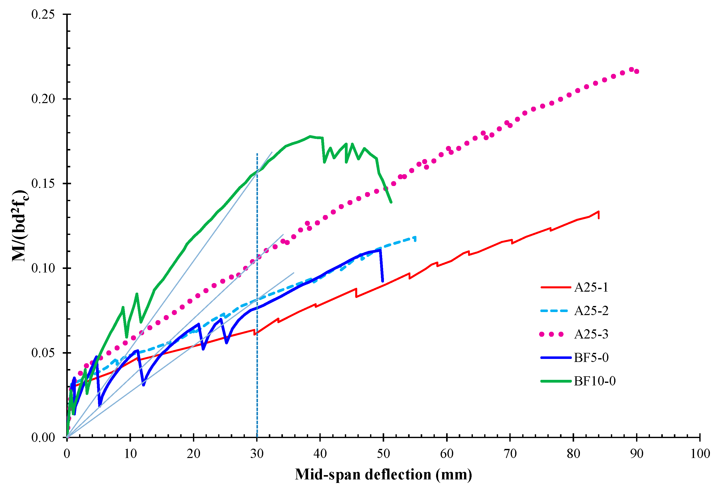
Comparisons of experimental results for beams BF5-0 and BF10-0 with beams reinforced with G-FRP bars (beams A25-1, A25-2, A25-3) extracted from recent literature [40] are presented in Figure 10. The geometrical and mechanical characteristics of specimens A25-1, A25-2, A25-3, with G-FRP bars [40] have some similarities with the characteristics of the beams with C-FRP bars examined in this study and, therefore, their response could be compared. Particularly, all beams reinforced with G-FRP bars have total length 2.8 m, width to height ratio b/h = 120/300 mm, shear span a = 1.1 m, top compression G-FRP reinforcement 2∅8, transverse steel closed stirrups ∅8/150 mm, concrete compressive strength fc = 24.5 MPa and tensile strength of the GFRP bars ffu = 640 MPa. The bottom tension G-FRP reinforcement (or its geometrical ratio, ρf) varies as follows: 2∅8 (or 0.33%) for specimen A25-1, 1∅12 + 1∅8 (or 0.54%) for specimen A25-2 and 2∅12 + 1∅8 (or 0.90%) for specimen A25-3.
It is also mentioned that in Figure 10 the moment is normalized using the well-known non-dimensioned factor M/(bd2fc), where b is the width, d is the effective depth and fc is the concrete compressive strength of the beams, in order the response of the examined specimens to be compared directly.
As expected, beams with C-FRP bars exhibit higher flexural stiffness than the beams with G-FRP bars; thus, for deflection equal to 30 mm beam BF10-0 exhibited:
- 40% higher flexural chord stiffness than the one of the beam A25-3 [40] although the mechanical reinforcement ratio ωf = ρfffu/fc in both beams are equal (ωf = 0.24) and
- 78% higher flexural chord stiffness than the one of the beam A25-2 [40] although the cross section areas of the FRP bars in both beams are almost alike (approximately 160 mm2)
6. Calculations of Strength and Deflections—Modern Codes
6.1. Flexural Strength
According to ACI 440.1R-15 [22] the flexural strength of a concrete beam reinforced with longitudinal FRP bars can be determined based on strain compatibility, internal force equilibrium, and the controlling mode of failure (concrete crushing or FRP rupture). The predicted failure mode can be determined by comparing the tensional FRP geometrical reinforcement ratio, ρf, to the balanced FRP reinforcement ratio, ρfb, which is the ratio where concrete crushing and FRP rupture occur simultaneously and calculated by the expression
where fc is the concrete cylinder compressive strength, εcu is the ultimate compressive strain of concrete (at the extreme compression fiber) taken equal to 3 ‰, Ef is the modulus of elasticity and ffu is the guaranteed (nominal) ultimate tensile strength of the FRP bars.
If ρf > ρfb the beam is considered as over-reinforced, the controlling limit state is crushing of concrete and the flexural strength, Mn,ACI, can be calculated using the expression
where b and d are the width and the effective depth of the beam and ff is the tensile strength of the FRP bars calculated as
Otherwise, if ρf ≤ ρfb the beam is considered as under-reinforced, the controlling limit state is fibers rupture of the FRP bars and the flexural strength, Mn, can be estimated as
where Af is the cross-sectional area of the FRP bars and c is the neutral axis depth of the beam.
According to CSA S806-12 [44], FRP reinforced concrete beams shall be designed in such a way that the controlling limit state is crushing of concrete and the ultimate compressive strain of concrete (at the extreme compression fiber) is taken equal to 3.5‰. Thus, the flexural strength, Mn,CSA, and the neutral axis depth of the beam, c, are calculated according to the expressions
where εf is the strain of the FRP bars that equals to ff/Ef.
6.2. Shear Strength
The calculation of the ultimate shear strength, Vn, of a FRP-reinforced concrete beam based on the provisions of ACI 440.1R-15 [22] and CSA S806-12 [44] is achieved using the sum
where Vc is the contribution of the un-cracked concrete chord and Vs is the contribution of the shear transverse steel reinforcement.
The difference between ACI 440.1R-15 [22] and CSA S806-12 [44] is the expression used for the calculation of the contribution of the un-cracked concrete chord, Vc
where nf = Ef/Ec, Ec is the elastic modulus of concrete, λ is a modification factor reflecting the reduced mechanical properties of lightweight concrete, taken as 1.00 for concrete with normal density, 0.85 for concrete with semi-low-density and natural sand for the fine aggregates, 0.75 for concrete with low-density and none of the fine aggregate is natural sand, Vf d/Mf (=d/a) shall not be taken greater than 1.0 and a is the shear span of the beam.
The shear strength of the transverse steel reinforcement (stirrups), Vs, is estimated according to both codes by the expression
where Av is the area, fyv is the yield tensile strength and s is the spacing of the steel stirrups.
6.3. Deflections and Comparisons with Test Results
Comparisons of the presented experimental results with the FRP design provisions described before are included herein. Nominal bending moment and shear capacities as specified in ACI 440.1R-15 [22] and to CSA S806-12 [44] are calculated and compared with the test results. The calculated values of the flexural and the shear strength of the examined RC beams with C-FRP bars are summarised in Table 2 (values of Mn and Vn, respectively). Based on these values, the expected failure mode and the analytically estimated total applied load (Pn) of the beams are also presented in Table 2. Overall the design recommendations for the concrete beams with C-FRP bars provided relatively conservative predictions compared to the test results since the examined Code provisions seem to underestimate the capacity of the beams. The predicted failure mode of the beams is in a very good compliance with the experimentally obtained one (see also Table 1).
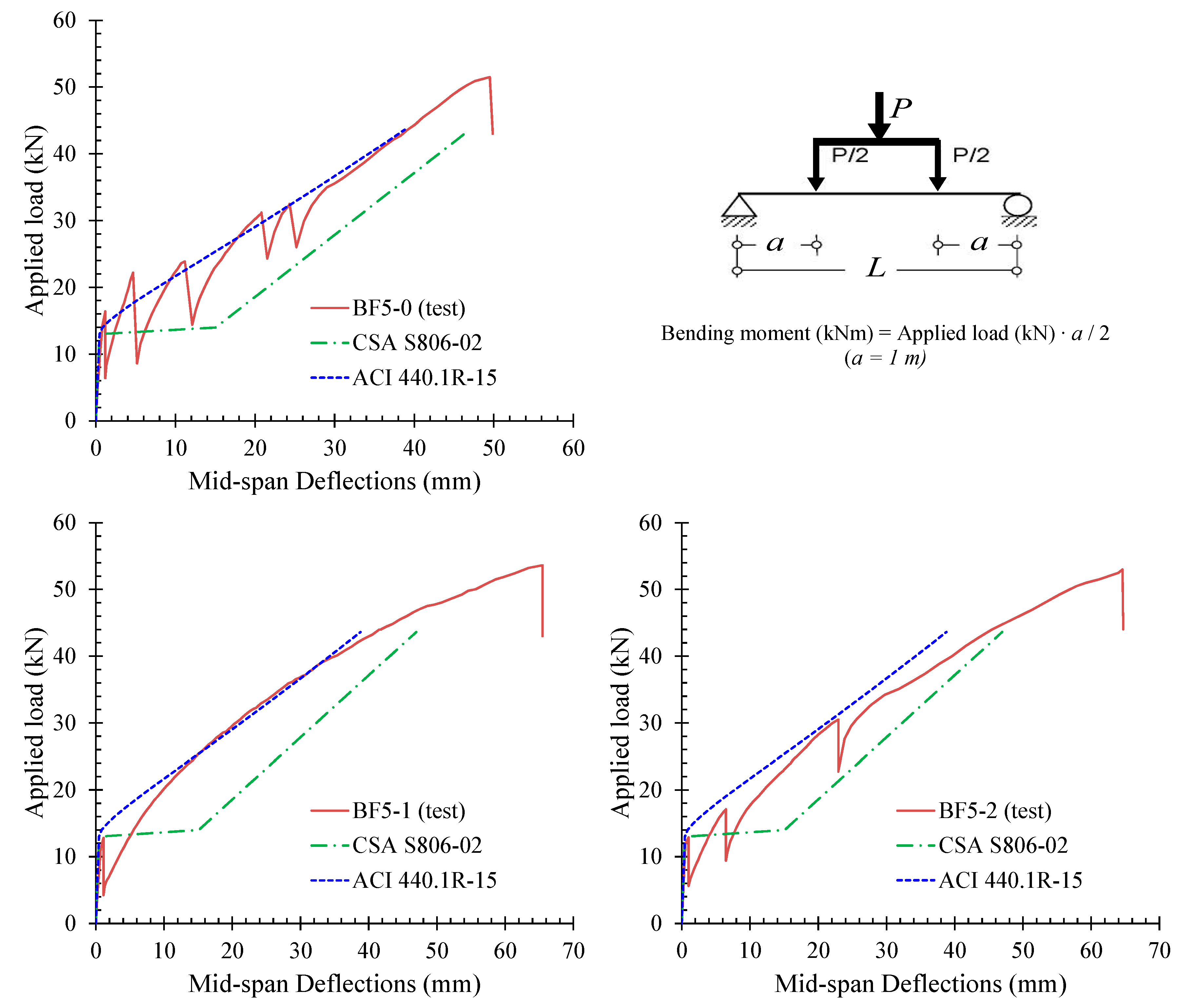
Furthermore, experimental load versus midspan deflections are compared with the corresponding calculations as prescribed by ACI 440.1R-15 [22] and CSA S806-12 [44]. For the calculation of the deflections according to ACI 440.1R-15 first the effective moment of inertia, Ie, used for calculation of cracked FRP reinforced beam has to be determined as
where Mα ≥ Mcr.
Equation (11) includes an integration factor, γ, which depends on the loading condition (such as three-point, or four-point, or uniform distributed load) and the boundary conditions (such as a simple supported beam, or with fixed ends, etc.). This factor according to Bischoff and Gross [46] and for a simply-supported beam with four-point loading can be estimated as
where Ma ≥ Mcr, a is the shear span and L is the length of the beam between the supports.
The integration factor, γ, accounts for the stiffness distribution along the FRP reinforced beam. Mα is the applied service moment and Mcr is the cracking moment calculated by the following expression
where fr is the modulus of rupture of concrete: fr = 0.6λ(fc)1/2 and yt is the distance from the centroidal axis of the gross cross-section to the tension face neglecting reinforcement. Furthermore, according to ACI 440.1R-15 [22] pre- and post-cracking deflections can be obtained using the following expressions for four-point loading, respectively
where P is the total applied load, a is the shear span or else distance between the loading P/2 and the support (see also Figure 11 for notation), Ec is the elastic modulus of concrete, Ig and Icr are gross and the cracked moment of inertia of the concrete section, respectively.
CSA S806-12 suggests the application of the moment versus curvature relationship to calculate the deflection that has been proved to be suitable for concrete beams with FRP bars. The method adopted by CSA S806-12 uses a tri-linear moment versus curvature model that includes three slope segments: (a) pre-cracking stiffness, EcIg; (b) zero slope that corresponds to the observed plateau length of the load-deflection curves shown in Figure 11; and (c) post-cracking stiffness, EcIcr. Pre-cracking deflection can be obtained using the well-known expression (17) for a simply supported beam with four-point loading, whereas for the calculation of the post-cracking deflection CSA S806-12 suggests expression (18).
- -
- Pre-cracking deflection
- -
- Post-cracking deflection
where η = 1 − Icr/Ig and Lg is the distance from the edge support to the point where the applied service moment and the cracking moment are equal: Ma = Mcr (for simply supported beams).
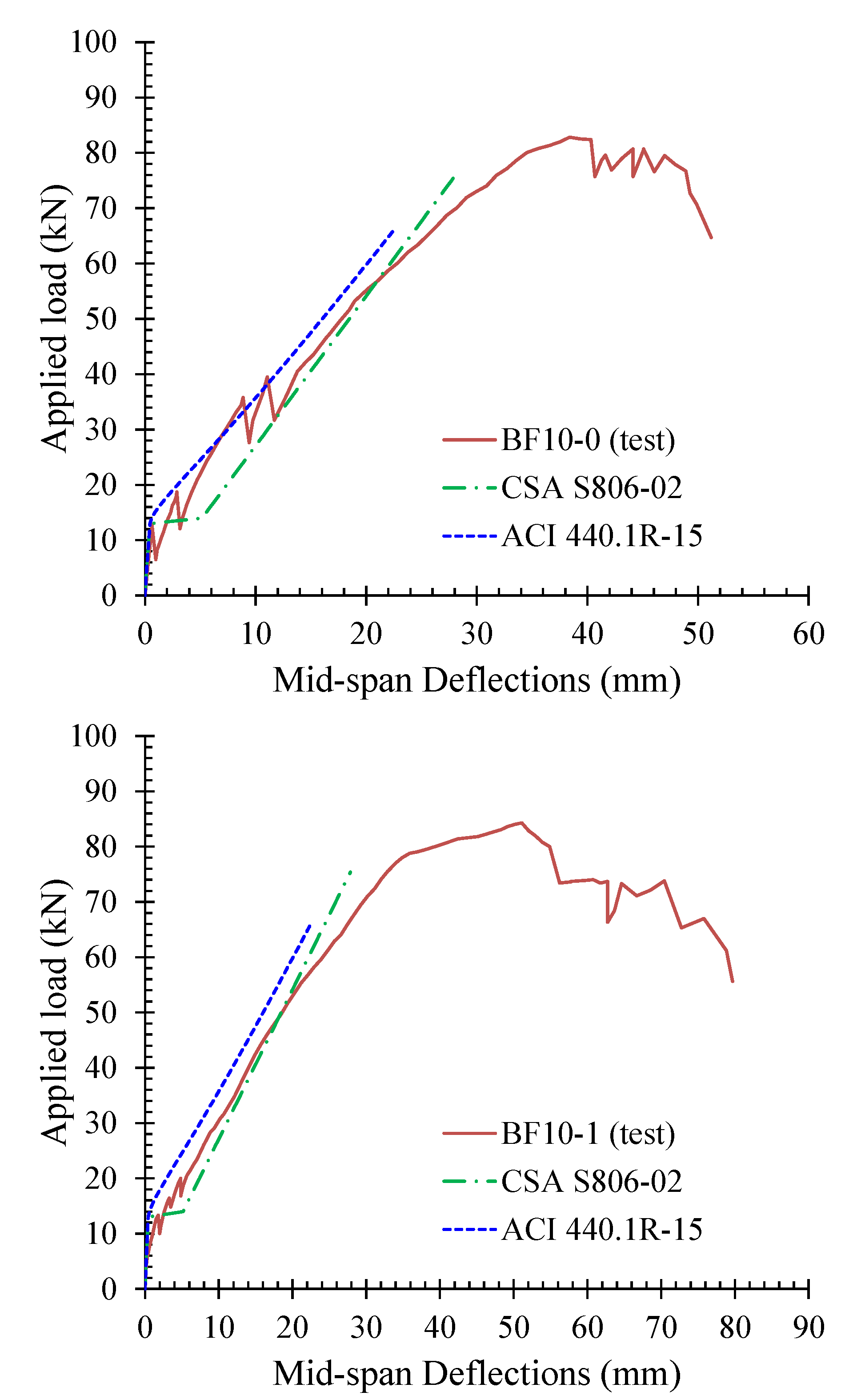
Comparisons of the experimental results with the predictions according to ACI 440.1R-15 and to CSA S806-12 for beams BF5-0, BF5-1, and BF5-2 are presented in Figure 11. Similarly, comparisons of the experimental results with the predictions according to ACI 440.1R-15 [22] and to CSA S806-12 [44] for beams BF10-0, BF10-1 are presented in Figure 12.
7. Concluding Remarks
Innovative materials manufactured of carbon fibers in polymer matrix have been proposed as alternatives for the substitution of the traditional steel bars in RC structures. Advantages of C-FRP bars in comparison to the conventional steel bars are the high corrosive-resistant behavior, the high tensile strength along the fibers and their lightweight non-magnetic features. However, the brittle behavior, the linear-elastic stress–strain response, the low modulus of elasticity and the low shear strength are shortcomings of these materials from the structural engineering point of view. In this work, the behavior of typical slender concrete beams reinforced with C-FRP bars under increasing static loading is experimentally investigated. Observed stiffness, maximum loading capacity, deflection per loading step, and development of the cracking width have been presented and commented. Special attention has been given in the bond conditions of the anchorage lengths of the tensile C-FRP bars. The results of this study showed that:
- The observed load versus midspan deflection curves include first a small pre-cracking part that exhibits high flexural stiffness while the main part of these curves is the post-cracking response that exhibits substantially lower stiffness than the one of the uncracked first part.
- A general observation from the deflection curves is that each time a crack appears in the concrete beams reinforced with C-FRP bars a sudden load drop is simultaneously occurred. It can be attributed to the fact that a local decrease of the stiffness undergo at the cracked section of the beam due to formation of long flexural cracks in combination with the low normalized reinforcement ratio of the C-FRP bars.
- Increasing of the C-FRP reinforcement ratio can possibly change the nature of the failure from pure flexural (series “BF5”) to a response with final failure in shear (series “BF10”).
- The application of the local spiral confinement conditions along the anchorage lengths of the C-FRP bars in some specimens (beams BF5-1, BF5-2, and BF10-1) seems to influence the development of the cracking system of these specimens. This influence appeared to be more intense in the case of the specimen BF5-1. The deflection at peak load of these beams seems also to be increased with regards to the corresponding beams without spirals. Nevertheless, more research is required in this direction.
- Comparisons of experimental results for C-FRP beams with beams reinforced with G-FRP bars extracted from recent literature have been presented and beams with C-FRP exhibited higher flexural stiffness than the beams with G-FRP bars.
- Comparisons of the experimental results with the predictions according to ACI 440.1R-15 and to CSA S806-12 have been also presented. The codes provisions successfully predicted the failure mode and seemed to be rather conservative.
Author Contributions
All authors contributed extensively to this study, discussed the results and reviews, prepared the manuscript and agreed to the amendments at all stages of the paper. P.-M.K.K. and C.E.C. constructed the beams and performed the tests under the supervision of C.G.K. who designed the experiments.
Funding
This research received no external funding.
Conflicts of Interest
The authors declare no conflict of interest.
References
- Karayannis, C.G.; Sirkelis, G.M. Strengthening and rehabilitation of RC beam—Column joints using carbon—FRP jacketing and epoxy resin injection. Earthq. Eng. Struct. Dyn. 2008, 37, 769–790. [Google Scholar] [CrossRef]
- Tsonos, A.G. Ultra-high-performance fiber reinforced concrete: An innovative solution for strengthening old R/C structures and for improving the FRP strengthening method. WIT Trans. Eng. Sci. 2009, 64, 273–284. [Google Scholar]
- Tsonos, A.G. Effectiveness of CFRP jackets in post-earthquake and pre-earthquake retrofitting of beam-column subassemblages. Struct. Eng. Mech. 2007, 27, 393–408. [Google Scholar] [CrossRef]
- Rousakis, T.C.; Tourtouras, I.S. RC columns of square section—Passive and active confinement with composite ropes. Compos. Part B Eng. 2014, 58, 573–581. [Google Scholar] [CrossRef]
- Kakaletsis, D. Comparison of CFRP and alternative seismic retrofitting techniques for bare and infilled RC frames. J. Compos. Constr. 2011, 15, 565–577. [Google Scholar] [CrossRef]
- Spyrakos, C.C.; Maniatakis, C.A.; Psycharis, I.N.; Smyarou, E.; Asteris, P.G. Validation of analytical models for the assessment of brick-infilled RC frames strengthened with FRPs. In Proceedings of the ECCOMAS Thematic Conference-COMPDYN, Kos Island, Greece, 12–14 June 2013; pp. 2978–2996. [Google Scholar]
- Chalioris, C.E. Analytical model for the torsional behaviour of reinforced concrete beams retrofitted with FRP materials. Eng. Struct. 2007, 29, 3263–3276. [Google Scholar] [CrossRef]
- Gopinath, S.; Murthy, A.R.; Patrawala, H. Near surface mounted strengthening of RC beams using basalt fiber reinforced polymer bars. Constr. Build. Mater. 2016, 111, 1–8. [Google Scholar] [CrossRef]
- Jabr, A.; El-Ragaby, A.; Ghrib, F. Effect of the fiber type and axial stiffness of FRCM on the flexural strengthening of RC beams. Fibers 2017, 5, 2. [Google Scholar] [CrossRef]
- Gribniak, V.; Tamulenas, V.; Ng, P.-L.; Arnautov, A.K.; Gudonis, E.; Misiunaite, I. Mechanical behavior of steel fiber-reinforced concrete beams bonded with external carbon fiber sheets. Materials 2017, 10, 666. [Google Scholar] [CrossRef]
- Chalioris, C.E.; Kosmidou, P.-M.K.; Papadopoulos, N.A. Investigation of a new strengthening technique for RC deep beams using carbon FRP ropes as transverse reinforcements. Fibers 2018, 6, 52. [Google Scholar] [CrossRef]
- Abdel-Mohti, A.; Shen, H. Strengthening of corroded reinforced SCC-RAP members with CFRP. Fibers 2016, 4, 3. [Google Scholar] [CrossRef]
- Napoli, A.; Matta, F.; Martinelli, E.; Nanni, A.; Realfonzo, R. Modelling and verification of response of RC slabs strengthened in flexure with mechanically fastened FRP laminates. Mag. Concr. Res. 2010, 62, 593–605. [Google Scholar] [CrossRef] [Green Version]
- Bellakehal, H.; Zaidi, A.; Masmoudi, R.; Bouhicha, M. Behavior of FRP bars-reinforced concrete slabs under temperature and sustained load effects. Polymers 2014, 6, 873–889. [Google Scholar] [CrossRef]
- Seyhan, E.C.; Goksu, C.; Uzunhasanoglu, A.; Ilki, A. Seismic behavior of substandard RC columns retrofitted with embedded Aramid Fiber Reinforced Polymer (AFRP) reinforcement. Polymers 2015, 7, 2535–2557. [Google Scholar] [CrossRef]
- Gouda, A.; El-Salakawy, E. Finite Element modeling of GFRP-reinforced concrete interior slab-column connections subjected to moment transfer. Fibers 2015, 3, 411–431. [Google Scholar] [CrossRef]
- Gouda, A.; El-Salakawy, E. Punching Shear Strength of GFRP-RC Interior Slab-Column Connections Subjected to Moment Transfer. J. Compos. Constr. 2016, 20, 04015037. [Google Scholar] [CrossRef]
- Gribniak, V.; Kaklauskas, G.; Torres, L.; Daniunas, A.; Timinskas, E.; Gudonis, E. Comparative analysis of deformations and tension-stiffening in concrete beams reinforced with GFRP or steel bars and fibers. Compos. Part B Eng. 2013, 50, 158–170. [Google Scholar] [CrossRef]
- Ju, M.; Park, L.; Park, C. Punching shear behavior of two-way concrete slabs reinforced with Glass-Fiber-Reinforced Polymer (GFRP) bars. Polymers 2018, 10, 893. [Google Scholar] [CrossRef]
- Toutanji, A.H.; Saafi, M. Flexural behavior of concrete beams reinforced with glass fiber-reinforced polymer (GFRP) bars. ACI Struct. J. 2000, 97, 712–719. [Google Scholar]
- Ovitigala, T.; Ibrahim, M.A.; Issa, M.A. Serviceability and ultimate load behavior of concrete beams reinforced with basalt fiber-reinforced polymer bars. ACI Struct. J. 2016, 113, 757–768. [Google Scholar] [CrossRef]
- ACI 440 Committee. Guide for the Design and Construction of Concrete Reinforced with FRP Bars (ACI440.1R-15); American Concrete Institute: Farmington Hills, MI, USA, 2015. [Google Scholar]
- Zadeh, H.J.; Nanni, A. Reliability analysis of concrete beams internally reinforced with fiber-reinforced polymer bars. ACI Struct. J. 2013, 110, 1023–1031. [Google Scholar]
- Tureyen, A.K.; Frosch, R.J. Concrete shear strength: Another perspective. ACI Struct. J. 2003, 100, 609–615. [Google Scholar]
- Gopinath, S.; Meenu, S.; Murthy, A.R. Shear strength evaluation of concrete beams reinforced with BFRP bars and steel fibers without stirrups. Comput. Mater. Cont. 2016, 51, 81–103. [Google Scholar]
- El-Sayed, A.K.; Soudki, K. Evaluation of shear design equations of concrete beams with FRP reinforcement. J. Compos. Constr. 2011, 15, 9–20. [Google Scholar] [CrossRef]
- Marí, A.; Cladera, A.; Oller, E.; Bairán, J. Shear design of FRP reinforced concrete beams without transverse reinforcement. Compos. Part B Eng. 2014, 57, 228–241. [Google Scholar] [CrossRef]
- Herwig, A.; Motavalli, M. Load-carrying capacity of GFRP bars under combined axial force–transverse force loading. Compos. Part B Eng. 2013, 44, 167–171. [Google Scholar] [CrossRef]
- Achillides, Z.; Pilakoutas, K. Bond behaviour of fiber reinforced polymer bars under direct pullout conditions. J. Compos. Constr. 2004, 8, 173–181. [Google Scholar] [CrossRef]
- Lin, X.; Zhang, Y.X. Bond–slip behaviour of FRP-reinforced concrete beams. Constr. Build. Mater. 2013, 44, 110–117. [Google Scholar] [CrossRef]
- Akbas, T.; Celik, O.; Yalcin, C.; Ilki, A. Monotonic and cyclic bond behavior of deformed CFRP bars in high strength concrete. Polymers 2016, 8, 211. [Google Scholar] [CrossRef]
- Lau, D.; Pam, H.J. Experimental study of hybrid FRP reinforced concrete beams. Eng. Struct. 2010, 32, 3857–3865. [Google Scholar] [CrossRef]
- Qin, R.; Zhou, A.; Lau, D. Effect of reinforcement ratio on the flexural performance of hybrid FRP reinforced concrete beams. Compos. Part B Eng. 2017, 108, 200–209. [Google Scholar] [CrossRef]
- Bencardino, F.; Condello, A.; Ombres, L. Numerical and analytical modeling of concrete beams with steel, FRP and hybrid FRP-steel reinforcements. Compos. Struct. 2016, 140, 53–65. [Google Scholar] [CrossRef]
- Ascione, L.; Mancusi, G.; Spadea, S. Flexural behaviour of concrete beams reinforced with GFRP bars. Strain 2010, 46, 460–469. [Google Scholar] [CrossRef]
- Konsta-Gdoutos, M.; Karayannis, C. Flexural behaviour of concrete beams reinforced with FRP bars. Adv. Compos. Lett. 1998, 7, 133–137. [Google Scholar]
- Vijay, P.; GangaRao, H.V. Bending behaviour and deformability of glass fiber-reinforced polymer reinforced concrete members. ACI Struct. J. 2001, 98, 834–842. [Google Scholar]
- Mota, C.; Alminar, S.; Svecova, D. Critical review of deflection formulas for FRP-RC members. J. Compos. Constr. 2006, 10, 183–194. [Google Scholar] [CrossRef]
- Issa, M.; Metwally, I.; Elzeiny, S. Influence of fibers on flexural behaviour and ductility of concrete beams reinforced with GFRP fibers. Eng. Struct. 2011, 33, 1754–1763. [Google Scholar] [CrossRef]
- Adam, M.; Said, M.; Mahmoud, A.; Shanour, A. Analytical and experimental flexural behaviour of concrete beams reinforced with glass fiber reinforced polymers bars. Constr. Build. Mater. 2015, 84, 354–366. [Google Scholar] [CrossRef]
- Maranan, G.B.; Manalo, A.C.; Benmokrane, B.; Karunasena, W.; Mendis, P.; Nguyen, T.Q. Shear behaviour of geopolymer-concrete beams transversely reinforced with continuous rectangular GFRP composite spirals. Compos. Struct. 2018, 187, 454–465. [Google Scholar] [CrossRef]
- Goldston, M.W.; Remennikov, A.; Sheikh, M.N. Experimental investigation of the behaviour of concrete beams reinforced with GFRP bars under static and impact loading. Eng. Struct. 2016, 113, 220–232. [Google Scholar] [CrossRef] [Green Version]
- Goldston, M.W.; Remennikov, A.; Sheikh, M.N. Flexural behaviour of GFRP reinforced high strength and ultra high strength concrete beams. Constr. Build. Mater. 2017, 131, 606–617. [Google Scholar] [CrossRef] [Green Version]
- CSA Standard. Design and Construction of Building Structures with Fibre-Reinforced Polymers (CSA S806–S12); Canadian Standards Association: Mississauga, ON, Canada, 2012. [Google Scholar]
- Tsonos, A.G. An innovative solution for strengthening of old R/C structures and for improving the FRP strengthening method. Struct. Monit. Maint. 2014, 1, 323–338. [Google Scholar] [CrossRef]
- Bischoff, P.H.; Gross, S.P. Equivalent moment of inertia based on integration of curvature. J. Compos. Constr. 2011, 15, 263–273. [Google Scholar] [CrossRef]
Figure 1.
Geometry, reinforcement, and cross-section details of beam specimens (dimensions in mm).

Figure 2.
Application of local confinement along the anchorage length of the C-FRP bars for specimens BF5-1 (above figure), BF5-2, and BF10-1 (dimensions in mm).
Figure 2.
Application of local confinement along the anchorage length of the C-FRP bars for specimens BF5-1 (above figure), BF5-2, and BF10-1 (dimensions in mm).

Figure 3.
Experimental setup and instrumentation (specimen BF5-0).

Figure 4.
Beam BF5-0. Load to midspan deflection (1) and load to crack width (2) observed curves. Photographs at characteristic points (a–f). Sequence of appearance of the observed cracks (3).
Figure 4.
Beam BF5-0. Load to midspan deflection (1) and load to crack width (2) observed curves. Photographs at characteristic points (a–f). Sequence of appearance of the observed cracks (3).

Figure 5.
Beam BF5-1. Load to midspan deflection (1) and load to crack width (2) observed curves. Photographs at characteristic points (a–f). Sequence of appearance of the observed cracks (3).
Figure 5.
Beam BF5-1. Load to midspan deflection (1) and load to crack width (2) observed curves. Photographs at characteristic points (a–f). Sequence of appearance of the observed cracks (3).

Figure 6.
Beam BF5-2. Load to midspan deflection (1) and load to crack width (2) observed curves. Photographs at characteristic points (a–f). Sequence of appearance of the observed cracks (3).
Figure 6.
Beam BF5-2. Load to midspan deflection (1) and load to crack width (2) observed curves. Photographs at characteristic points (a–f). Sequence of appearance of the observed cracks (3).

Figure 7.
Beam BF10-0. Load to midspan deflection (1) and load to crack width (2) observed curves. Photographs at characteristic points (a–f). Sequence of appearance of the observed cracks (3).
Figure 7.
Beam BF10-0. Load to midspan deflection (1) and load to crack width (2) observed curves. Photographs at characteristic points (a–f). Sequence of appearance of the observed cracks (3).

Figure 8.
Beam BF10-1. Load to midspan deflection (1) and load to crack width (2) observed curves. Photographs at characteristic points (a–f). Sequence of appearance of the observed cracks (3).
Figure 8.
Beam BF10-1. Load to midspan deflection (1) and load to crack width (2) observed curves. Photographs at characteristic points (a–f). Sequence of appearance of the observed cracks (3).

Figure 9.
Comparison of the load to midspan deflection curves of the tested beams.

Figure 10.
Comparison of test results for C-FRP reinforced beams BF5-0 and BF10-0 (present study) with beams reinforced with G-FRP bars (beams A25-1, A25-2, A25-3 from literature [40]).
Figure 10.
Comparison of test results for C-FRP reinforced beams BF5-0 and BF10-0 (present study) with beams reinforced with G-FRP bars (beams A25-1, A25-2, A25-3 from literature [40]).

Figure 11.
Comparisons of the test results with the predictions according to ACI 440.1R-15 and to CSA S806-12 for beams BF5-0, BF5-1, and BF5-2. FRP reinforcement of series “BF5” beams: ρf = 0.12%.
Figure 11.
Comparisons of the test results with the predictions according to ACI 440.1R-15 and to CSA S806-12 for beams BF5-0, BF5-1, and BF5-2. FRP reinforcement of series “BF5” beams: ρf = 0.12%.

Figure 12.
Comparisons of the test results with the predictions according to ACI 440.1R-15 and to CSA S806-12 for beams BF10-0 and BF10-1. FRP reinforcement of series “BF10” beams: ρf = 0.39%.
Figure 12.
Comparisons of the test results with the predictions according to ACI 440.1R-15 and to CSA S806-12 for beams BF10-0 and BF10-1. FRP reinforcement of series “BF10” beams: ρf = 0.39%.


Table 1.
Characteristics of the tested beams and experimental results.
| Group | Beam Name | Type and Diameter | Tensional Bars | Experimental Results | |||||
|---|---|---|---|---|---|---|---|---|---|
| ρ 1 (%) | ρf 2 (MPa) | ω 3 | Pexp (kN) | Vexp = Mexp (kN) or (kNm) | δpeak (mm) | Observed Failure 4 | |||
| “S” | S10 | 2∅10 | 0.39 | 2.16 | 0.07 | 30.6 * 35.0 | 15.3 * 17.5 | 6.0 * 62.8 | Y |
| S12 | 2∅12 | 0.57 | 3.11 | 0.11 | 45.2 * 53.6 | 22.6 * 26.8 | 11.1 * 63.8 | Y | |
| “BF5” | BF5-0 | 2HD5.5 | 0.12 | 2.14 | 0.07 | 51.6 | 25.8 | 49.5 | F-R |
| BF5-1 | 2HD5.5 | 0.12 | 2.14 | 0.07 | 53.6 | 26.8 | 65.5 | F-R | |
| BF5-2 | 2HD5.5 | 0.12 | 2.14 | 0.07 | 52.4 | 26.2 | 64.6 | F-R | |
| “BF10” | BF10-0 | 2HD10 | 0.39 | 7.07 | 0.24 | 82.8 | 41.4 | 38.4 | S-T |
| BF10-1 | 2HD10 | 0.39 | 7.07 | 0.24 | 84.4 | 42.2 | 51.1 | S-T | |
1 Geometrical reinforcement ratio: ρs for the steel bars and ρf for the C-FRP bars. 2 Geometrical reinforcement ratio × tensile strength: ρsfy for the steel bars and ρfffu for the C-FRP bars. 3 Mechanical reinforcement ratio: ωs = ρsfy/fc for the steel bars and ωf = ρfffu/fc for the C-FRP bars. 4 Failure mode notation: Y: Typical flexural failure after steel Yielding with adequate ductility; F-R: Flexural failure due to the rupture of the carbon fibers of the C-FRP bars; S-T: Shear failure due to the diagonal Tension cracking. * Test results at steel yielding.
| Group | Beam Name | Flexural Strength | Shear Strength | Predicted Failure 1,2 | Comparisons with Tests 2 | |||||
|---|---|---|---|---|---|---|---|---|---|---|
| Mn,ACI (kNm) | Mn,CSA (kNm) | Vn,ACI (kN) | Vn,CSA (kN) | Pn,ACI (kN) | Pn,CSA (kN) | |||||
| “BF5” | BF5-0 | 21.8 | N/A | 26.5 | 31.0 | F-R | 43.6 | 0.84 | N/A | N/A |
| BF5-1 | 21.8 | N/A | 26.5 | 31.0 | F-R | 43.6 | 0.81 | N/A | N/A | |
| BF5-2 | 21.8 | N/A | 26.5 | 31.0 | F-R | 43.6 | 0.83 | N/A | N/A | |
| “BF10” | BF10-0 | 58.9 | 65.8 | 33.1 | 37.7 | S-T | 66.2 | 0.80 | 75.4 | 0.91 |
| BF10-1 | 58.9 | 65.8 | 33.1 | 37.7 | S-T | 66.2 | 0.78 | 75.4 | 0.89 | |
N/A: non-applied since CSA S806-12 [44] considers “concrete crushing” as the only controlling limit state). 1 Failure mode notation: F-R: flexural failure due to the Rupture of the carbon fibers of the C-FRP bars; S-T: Shear failure due to the diagonal tension cracking. 2 Failure mode definition (a = 1 m): if Mn ≤ Vn → F-R (flexural failure) and Pn = 2Mn; if Mn > Vn → S-T (shear failure) and Pn = 2Vn.
© 2018 by the authors. Licensee MDPI, Basel, Switzerland. This article is an open access article distributed under the terms and conditions of the Creative Commons Attribution (CC BY) license (http://creativecommons.org/licenses/by/4.0/).
Share and Cite
MDPI and ACS Style
G. Karayannis, C.; K. Kosmidou, P.-M.; E. Chalioris, C. Reinforced Concrete Beams with Carbon-Fiber-Reinforced Polymer Bars—Experimental Study. Fibers 2018, 6, 99. https://0-doi-org.brum.beds.ac.uk/10.3390/fib6040099
AMA Style
G. Karayannis C, K. Kosmidou P-M, E. Chalioris C. Reinforced Concrete Beams with Carbon-Fiber-Reinforced Polymer Bars—Experimental Study. Fibers. 2018; 6(4):99. https://0-doi-org.brum.beds.ac.uk/10.3390/fib6040099
Chicago/Turabian StyleG. Karayannis, Chris, Parthena-Maria K. Kosmidou, and Constantin E. Chalioris. 2018. "Reinforced Concrete Beams with Carbon-Fiber-Reinforced Polymer Bars—Experimental Study" Fibers 6, no. 4: 99. https://0-doi-org.brum.beds.ac.uk/10.3390/fib6040099
Note that from the first issue of 2016, this journal uses article numbers instead of page numbers. See further details here.