ANN-Based Shear Capacity of Steel Fiber-Reinforced Concrete Beams without Stirrups


1
Abambres’ Lab, 1600-275 Lisbon, Portugal
2
Escola de Tecnologias e Engenharia, Instituto Superior de Educação e Ciências (ISEC), 1750-142 Lisbon, Portugal
3
Politécnico, Universidad San Francisco de Quito, Sector Cumbaya, EC 170157 Quito, Ecuador
4
Department of Civil Engineering and Geosciences, Delft University of Technology, 2628 CN Delft, The Netherlands
*
Author to whom correspondence should be addressed.
Fibers 2019, 7(10), 88; https://0-doi-org.brum.beds.ac.uk/10.3390/fib7100088
Submission received: 30 August 2019
/
Revised: 25 September 2019
/
Accepted: 26 September 2019
/
Published: 11 October 2019
(This article belongs to the Special Issue Steel Fibre Reinforced Concrete Behaviour)
Abstract
:Comparing experimental results of the shear capacity of steel fiber-reinforced concrete (SFRC) beams without stirrups to the capacity predicted using current design equations and other available formulations shows that predicting the shear capacity of SFRC beams without mild steel shear reinforcement is still difficult. The reason for this difficulty is the complex mechanics of the problem, where the steel fibers affect the different shear-carrying mechanisms. Since this problem is still not fully understood, we propose the use of artificial intelligence (AI) to derive an expression based on the available experimental data. We used a database of 430 datapoints obtained from the literature. The outcome is an artificial neural network-based expression to predict the shear capacity of SFRC beams without shear reinforcement. For this purpose, many thousands of artificial neural network (ANN) models were generated, based on 475 distinct combinations of 15 typical ANN features. The proposed “optimal” model results in maximum and mean relative errors of 0.0% for the 430 datapoints. The proposed model results in a better prediction (mean Vtest/VANN = 1.00 with a coefficient of variation 1 × 10⁻¹⁵) as compared to the existing code expressions and other available empirical expressions, with the model by Kwak et al. giving a mean value of Vtest/Vpred = 1.01 and a coefficient of variation of 27%. Until mechanics-based models are available for predicting the shear capacity of SFRC beams without shear reinforcement, the proposed model thus offers an attractive solution for estimating the shear capacity of SFRC beams without shear reinforcement. With this approach, designers who may be reluctant to use SFRC because of the large uncertainties and poor predictions of experiments, may feel more confident using the material for structural design.
1. Introduction
Because concrete is strong in compression but weak in tension, adding fibers to the material can be a solution for the limited strength in tension. In structural applications, fiber-reinforced concrete is combined with regular reinforcement steel. The type of fibers that are used, are most often steel fibers. These fibers help to distribute cracks and keep the crack widths small [1].
One failure mode where crack shape and width is essential, is shear failure. When steel fibers are included in the concrete mix, and the reinforced concrete element built with this concrete mix is tested in shear, then the addition of the steel fibers influences all mechanisms that contribute to the shear-carrying capacity of the member [2]. Since the mechanics of the problem are still not fully understood, it is interesting to study the behavior of steel fiber-reinforced concrete (SFRC) with longitudinal steel reinforcement and without shear reinforcement. As such, we can study the contribution of steel fibers to the shear capacity of structural concrete, without the influence of the stirrups as shear reinforcement. Once this problem is understood, we can find an optimal combination of steel fiber reinforcement and regular stirrups to act as shear reinforcement. Such a combination is particularly interesting in joints where rebar congestion can make concreting difficult [3], and for bridge girders, where the addition of steel fibers can lead to a more durable structure as cracks will be more distributed and crack widths will be smaller.
Even though the mechanics of the shear resistance of SFRC is not fully understood, several design expressions are available in the literature and current codes. These expressions are mostly semi-empirical expressions, with the exception of extensions of the Modified Compression Field Theory [4,5,6,7,8,9,10,11,12], the Dual Potential Capacity Model [13,14], and plasticity-based models [15,16,17,18,19]. Table 1 gives an overview of the expressions for determining the shear capacity of SFRC beams without shear reinforcement from the literature that were considered in this study for comparison [20]. In these expressions, the properties of the fibers are often described by the fiber factor F [19]:
with Vf the fiber volume fraction, lf the length of the fiber, df the diameter of the fiber, and ρf the fiber bond factor, which depends on the fiber type. An overview of the notations used in Table 1 is given in the List of Notations at the end of this article.
For small values of a/d (typically a/d < 2.5) the shear behavior is different than for larger shear span to depth ratios. The reason for this difference in behavior is that for short shear spans a compressive strut can develop between the point of application of the load and the support [21]. This additional load-carrying mechanism enhances the shear capacity. In Table 1, this behavior is reflected by the inclusion of a factor, such as e in Equation (7) to enhance the shear capacity for short shear spans. Not all expressions from the literature include this effect. Where this effect is not included, the predicted shear capacities tend to be conservative for short shear spans.
Comparing experimental results on the shear capacity of SFRC beams without stirrups to the capacity predicted using the expressions from Table 1 shows that predicting the shear capacity of SFRC beams without mild steel shear reinforcement is still difficult [20]. The reason for this difficulty is the complex mechanics of the problem, since, as previously mentioned, the steel fibers affect each of the shear-carrying mechanisms [2].
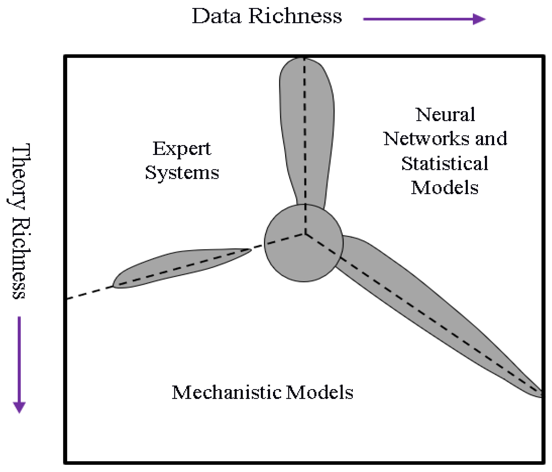
Since the problem of the shear capacity of SFRC elements without shear reinforcement is still not fully understood, we propose the use of machine learning, and in particular the use of artificial neural networks (ANNs or neural nets) to derive an expression based on the available experimental data. Machine learning is a subdiscipline of artificial intelligence (AI) in which computers learn how to carry out tasks based on examples of how they should be done [37]. When we have a lot of data but no theoretical foundations to explain these, machine learning can be a suitable tool. An illustration of the several possible scenarios is presented in [38], see Figure 1, where the shadowed areas represent regions where any of the contiguous tools might be used. The ANN is the oldest [39] and most powerful [40] machine learning technique. Generally speaking, an ANN is an analytical model for a singular task, functioning similarly to the human brain by using neurons. ANN is more powerful than traditional approaches (e.g., multi-variate nonlinear regression) and does not require prior knowledge of the shape of the function that will be approximated [41].
Several the expressions in Table 1 have been developed with methods of AI. The equation by Sarveghadi et al. [22] is derived from a more general expression developed with the use of artificial neural networks. The expression by Greenough and Nehdi [24] results from genetic programming. Other studies that used AI to evaluate the shear capacity of SFRC beams are the study by Hossain et al. [42] based on 173 experiments, resulting in an ANN model with 5 hidden neurons. The mean square error of the comparison between the experiments and the proposed model was 3.0665 and the root mean square error 1.7512. The study by Kara [43] used gene expression programming. In total, 101 experiments from the literature were used. Comparison between the proposed model and the experiments gave an absolute average error of 11.39% and a coefficient of variation of 15.42%. Other recent research works that have considered databases of experiments have used smaller databases than this study: 122 experiments [11] or 171 experiments (of which 93 with Fiber Reinforced Concrete) [44].
The goal of this study is to derive an ANN-based model to predict the shear capacity of SFRC elements without stirrups within the ranges of the available experimental data. While similar studies have been carried out in the past, as discussed in the previous paragraph, our study is an improvement of the state-of-the-art for the following reasons: (1) the dataset used for this study contains 430 experiments, which is significantly larger than the datasets used in the previous studies; (2) a large number of ANN features were varied, resulting in 475 combinations of features, with which the model that best predicts the experimental results could be selected; and (3) the error of the comparison between the proposed model and the experimental results is 0%, showing that the model proposed with this study is a significant improvement as compared to the previously cited models.
2. Materials and Methods
2.1. Data Gathering
We used a database of test results reported in the literature as input for the model. The database is earlier reported in [20]. To create unique datapoints, the outcome of repeat tests is averaged. Therefore, the original dataset of 488 test results is reduced to 430 unique datapoints considered for this study. As a result, some of the inherent scatter observed in repeat tests is removed from the database. The reader should keep this preprocessing in mind when evaluating the performance of the proposed model. The experimental results are taken from the literature [3,17,23,24,26,27,28,45,46,47,48,49,50,51,52,53,54,55,56,57,58,59,60,61,62,63,64,65,66,67,68,69,70,71,72,73,74,75,76,77,78,79,80,81,82,83,84,85,86,87,88,89,90,91,92,93,94,95,96,97,98,99,100,101,102].
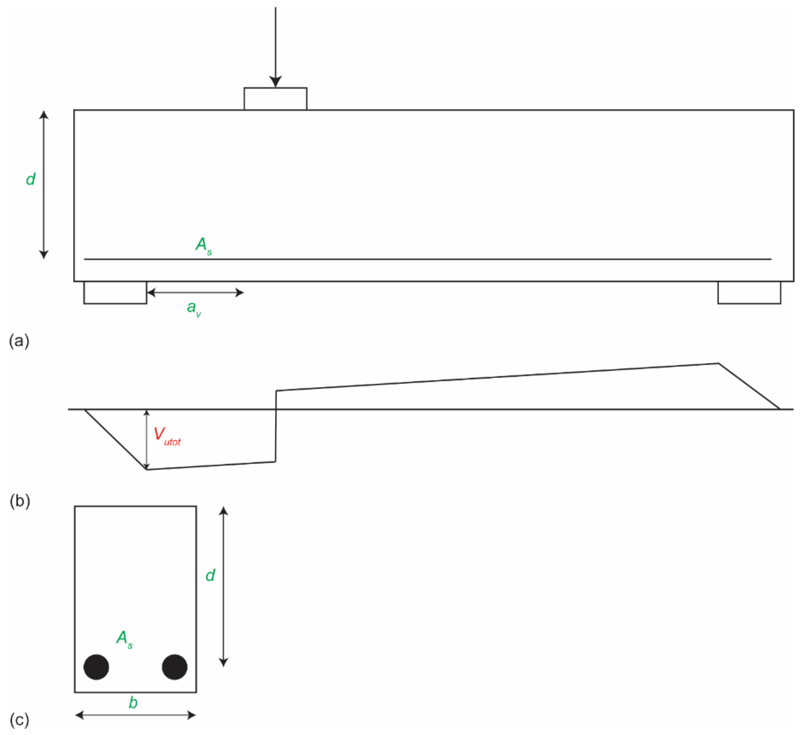
Table 2 gives an overview of the input and output values considered in this study. The geometry is described based on the effective depth d, the width b and the clear shear span to effective depth ratio av/d. Figure 2 shows the geometry of a typical beam specimen. The properties of the steel reinforcement are determined based on the reinforcement ratio ρ, which is defined as follows:
with As the area of longitudinal reinforcement. The other parameter determining the reinforcement is the yield strength of the steel fy. The properties of the concrete mix are described by the maximum aggregate size da and the measured average concrete cylinder compressive strength fc. The properties of the fibers are given through the fiber factor F according to Equation (1) as well as the tensile strength of the fibers ftenf. The output is the sectional shear capacity Vutot, determined as shown in Figrue 2b. Vutot includes the effect of the self-weight of the beam. In total, nine input variables and one output variable are selected.
Table 2 also gives an overview of the ranges of the input variables in the dataset used for the development of the model. The currently available test results come from relatively small specimens, as can be seen in Table 2. With a maximum effective depth of 1118 mm, the available experimental data may not sufficiently address the size effect in shear for SFRC [103,104,105,106]. The data moreover show that most experimental data come from small-scale specimens. A wide range values for av/d is covered, so that the model resulting from the database can be used for deep members as well as for slender members.
The reinforcement ratios used in the experiments cover a wide range. The majority of SFRC shear experiments are carried out on heavily reinforced beams, to avoid a flexural failure. These large reinforcement ratios are not commonly used in practice. Considering the range of aggregate sizes available in the database, we can observe that both mortars and concretes are used for the experiments in the literature. The concrete compressive strength range shows that mixes from low strength to ultra-high-strength concrete are used.
The fiber types used in the experiments reflect all commercially available fiber types (hooked-ended, corrugated, crimped, straight smooth, round), as well as some fiber types that were explored for research purposes (flat-ended, flat, chopped with butt ends, straight mild steel, mill-cut, recycled fibers, brass-coated high-strength steel), and mixes of different types (hooked-ended and straight). The bond factor ρf in the expression for the fiber factor F takes into account the effect of the fiber type. For the less commonly used fiber types, there may be discussion about which value to use for the bond factor. Most of the experiments (63% of all experiments) analyzed used hooked-end fibers. Most specimens use a fiber factor of 0.5–1; higher values result in concrete mixes with low workability.
Since the proposed matrix-based model using artificial neural networks is only as good as the input data used for the model, the reader should keep the aforementioned limitations regarding the parameters used in the experiments in mind when applying the resulting expression for the design of members with SFRC. Extrapolation of the proposed model outside of the ranges of data points considered in this study does not guarantee a good approximation. The dataset used for this research, as well as the calculated values with our proposed model, can be found online [107].
2.2. Artificial Neural Networks
2.2.1. Introduction
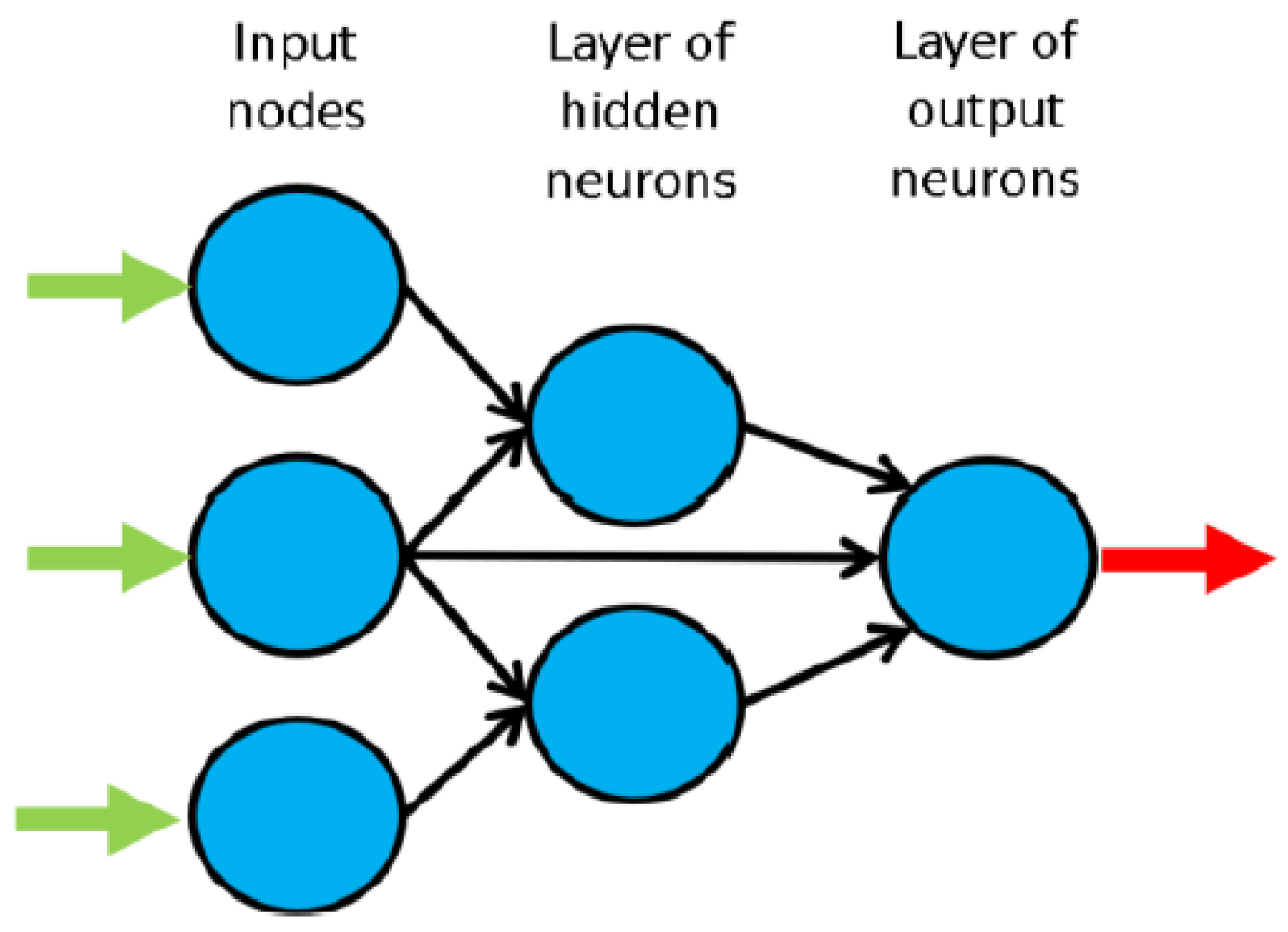
The neural net, see Figure 3, consists of L layers of several nodes, with the first layer the input layer, layers 2 to L-1 the hidden layers, and layer L the output layer. The ANNs in this work are feed-forward: neurons connect to nodes in the layers further down the net, see Figure 3. Each node, except those in the input layer, has the following unknowns associated with it: the (non)linear transfer function, the synaptic weights W, and the bias b. The transfer function is determined by trying out different possible functions. W and b are determined through learning: finding a (local) minimum solution so that pre-determined requirements for performance of the neural net are met. Learning has three stages: training, validation, and testing. The input dataset is subdivided into a training dataset (for determining the unknowns of the neural net), validation dataset (for checking the generalization performance—loss of this characteristic is called overfitting, which can be caused by the net learning properties of the noise on the available data [108]), and testing dataset (independent verification of performance of neural net).
2.2.2. Implemented ANN Features
This work considers 15 ANN features, including data pre/post-processing features. We used parametric analysis (using nine sub-analyses) to determine the features that best describe the problem at hand. Table 3, Table 4 and Table 5 give an overview of the different formats used for the 15 features, based on information in the literature. Previous work (e.g., [109]) contains full descriptions and references to the literature used to select the different methods for the feature. MATLAB [110] is used for programming these routines. The neural network toolbox of MATLAB is used for the most commonly used algorithms for learning (1–3 in Table 5). In each sub-analysis (SA) the software runs all possible combinations of neural nets for preselected approaches for the features. The output is then the performance of each trial net. The optimal net is then the net with the best performance: the net with the smallest average relative error. In addition to average relative error, we also evaluate maximum error, and percentage of errors larger than 3%. The definitions used to assess the performance of the resulting neural net are defined in [109]. The developed software has been validated with several benchmark datasets and functions—a full validation report is available in the public domain [111].
With respect to the ANN formulation used in [109], two fewer changes were carried out for this work: (1) the elimination of performance improvements (Feature 14), and (2) the algorithm used in Feature 4. For the current study, four distributions of data pt-pv-ptt (percentage for training, validation, and testing) were implemented (Feature 4). The following algorithm was implemented to divide the dataset into the training, validation, and testing subsets:
- Reduce pt-pv-ptt values by 10 units each.
- Compute minimum and maximum values for each variable q (row) of the full input dataset.
- Define patterns where each variable takes its minimum or maximum value from the full input dataset. These patterns ought to be included in the training dataset. If the number of patterns is lower than pt * P/100 (rounded off), more patterns should be added to the training set in the following way:
- (a)
- Compute the number of patterns (Lpt) that need to be added to the initially selected training patterns to equal round (pt * P/100).
- (b)
- Randomly select 10.000 combinations of Lpt patterns from all those not included in the training set defined prior to (a).
- (c)
- For each combination/scenario in (b), add those Lpt patterns to the set of training patterns defined prior to (a), and label all remaining learning patterns as “validation + testing”.
- (d)
- For each scenario in (c), and for each pattern labeled as “validation + testing”, check if that pattern has at least one input variable that equals a value not included in any pattern in the training set. If it hasn’t, then that pattern should be moved to the training set.
- (e)
- Among all 10,000 scenarios of training and “validation + testing” subsets addressed in (b) till (d), the selected scenario should be the one guaranteeing the amount of training data (Pt*) closest to round (pt * P/100).
- If the training set selected in (e) guarantees |Pt*/P − pt| ≤ 0.2, then that becomes the training data to be taken for simulation. Otherwise, the training data should be selected according to [112].
- Increase pt-pv-ptt values by 10 units each (to re-obtain the original input values—See step 1).
- Randomly select pv/(pv + ptt) of those patterns not belonging to the training dataset for the validation patterns. The remaining data then forms the testing dataset.
The distribution pt-pv-ptt in the simulation can differ from the one chosen a priori (before step 1).
2.2.3. Parametric Analysis Results
The software runs nine SAs, of preselected ANN features. Feature 7 takes a single value only in each of the SAs. The SAs serve the purpose of determining the best method for the features in a consecutive way. Further information on how the SAs are defined can be found in [109]. 475 combinations of features were explored through the SAs. Table 6 shows the best feature methods (that led to the combination with the best performance) from the different SAs. The numbers refer to those given in Table 3 through Table 5. Table 7 shows the performance results of the best combos of each SA. The results are obtained in the original format, compared to the actual values of the dataset. The microprocessor used in this work has the following features: RAM: 48 GB, OS: Win10Home 64bits, CPU: Intel® Core™ i7 8700K @ 3.70-4.70 GHz, Local Disk Memory: 1 TB.
3. Results
3.1. Proposed ANN-Based Model
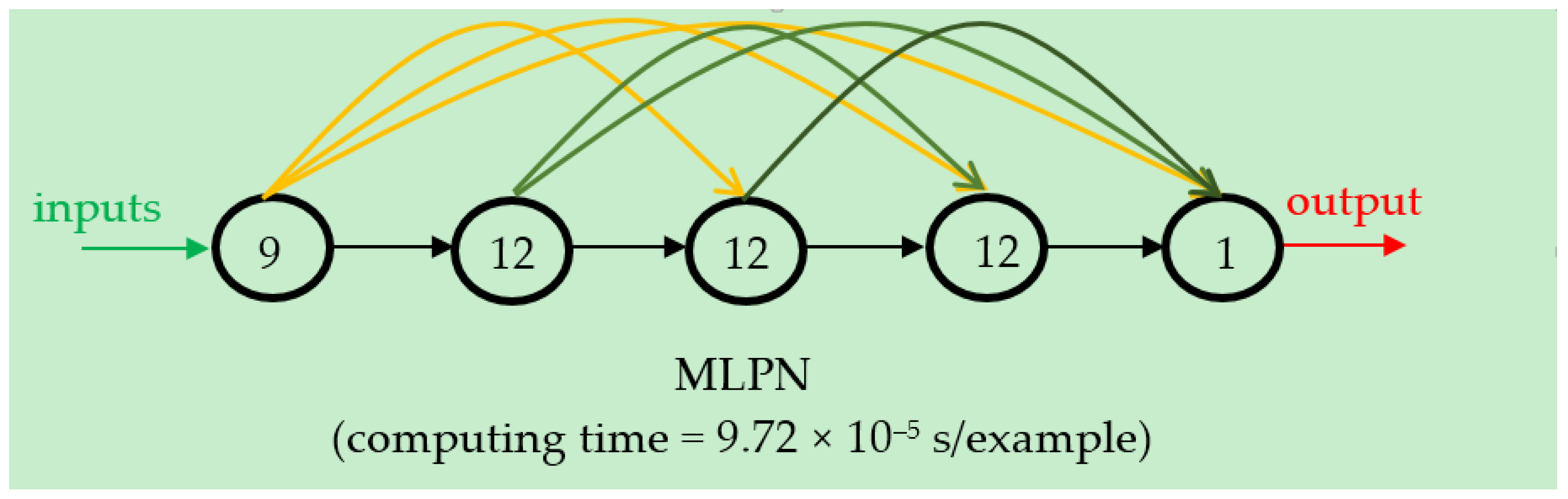
The proposed model is the one with the best performance among the best nets of each SA. As can be seen in Table 7, the best performance is obtained for the best net of SA9. For any user to apply our proposed model, we will provide all relevant expressions in the following subparagraphs and have provided the W and b arrays for download from the public domain. The proposed model uses five layers, and has the following distribution of nodes per layer: 9 in the input layer, 12 in each hidden layer, 1 in the output layer, see Figure 4, which also shows the connectivity of the network. The performance results of the proposed model are detailed in §3.2. The calculated solution with our proposed model is also available in the public domain for easy comparison [113].
3.1.1. Preprocessing of Input Data
Features 2, 3, and 5 deal with preprocessing of the data. We found that dimensional analysis nor reduction were necessary. The expression for input normalization is given as follows, with the input data:
3.1.2. ANN-Based Analytical Model
The next part is the actual description of the ANN-based expression of our proposed model. They are presented here completely, with the W and b arrays in the public domain [113], so that all our results are reproducible. The following equations transfer the preprocessed input to the outputs of the hidden layers 2 through 4 and then to the preprocessed output
The following transfer functions are used:
3.1.3. Output Data Post-Processing
Since in our proposed model, no output normalization or dimensional analysis is used, the output from Equation (59) {Y5,sim}nafter is the final result .
3.2. Performance Indicators of Results
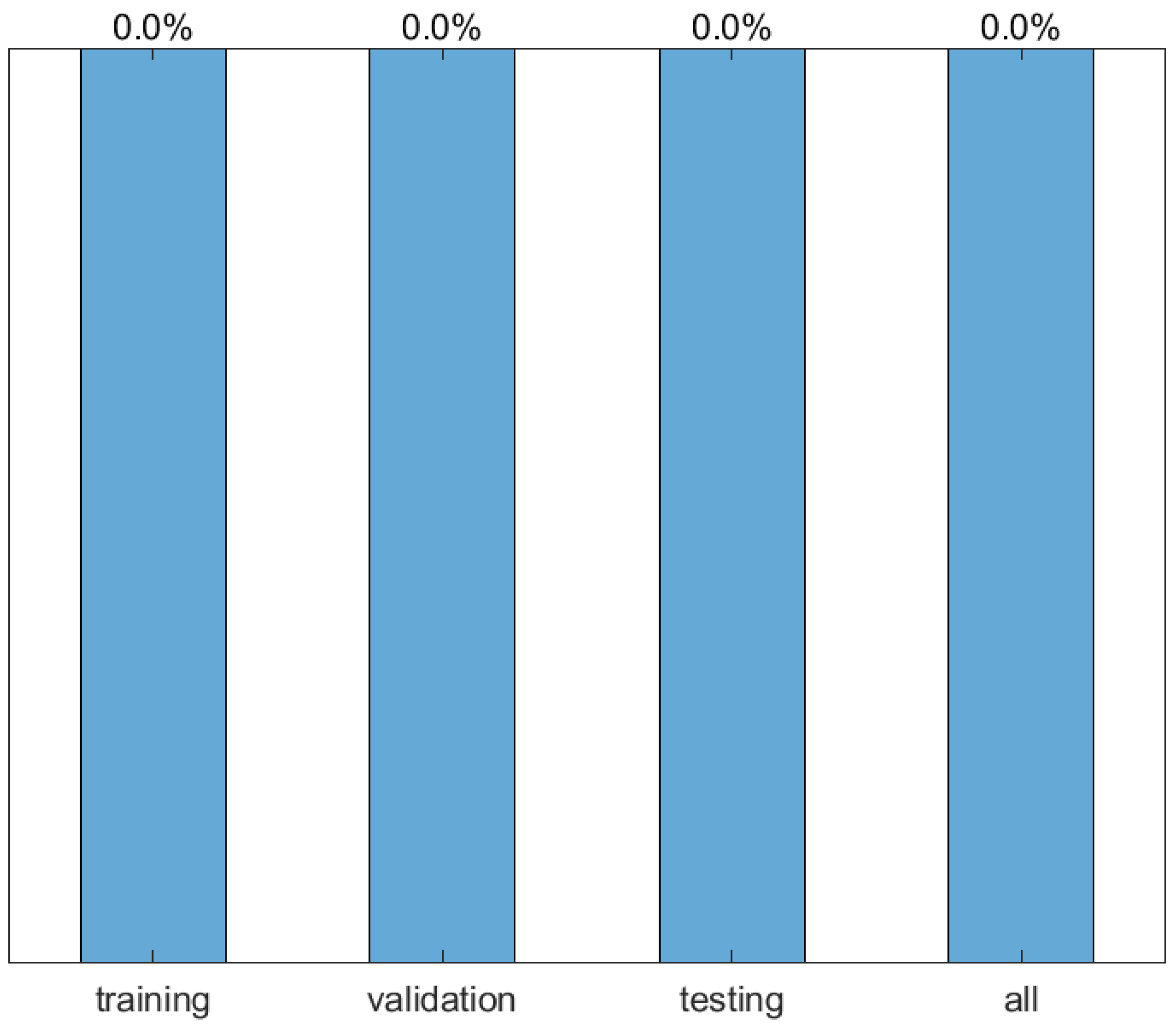
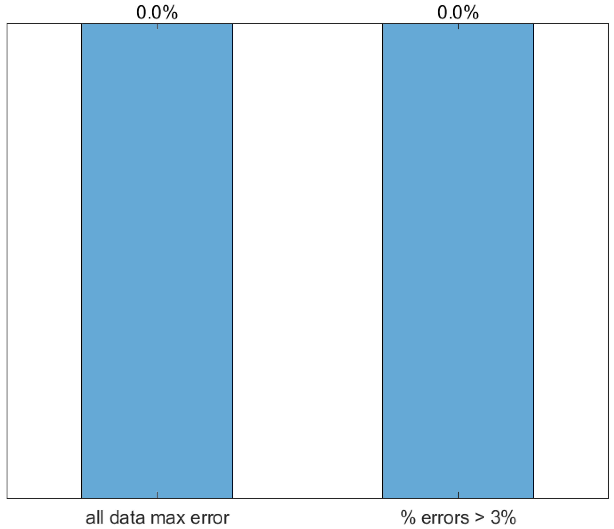
The performance of the proposed model is presented in this subsection. Figure 5 shows the regression plot of the relation between output of the dataset and network targets together with the Pearson Correlation Coefficient R. Figure 6 shows the average error values of the training, validation, and testing datasets, as well as of all data. Figure 7 shows the maximum error of all data as well as the percentage of data with an error above 3%. The reader should recall here that the outcome of repeat tests was averaged, so that some of the inherent material heterogeneity is removed to obtain unique datapoints.
3.3. Comparison between ANN-Based and Existing Methods
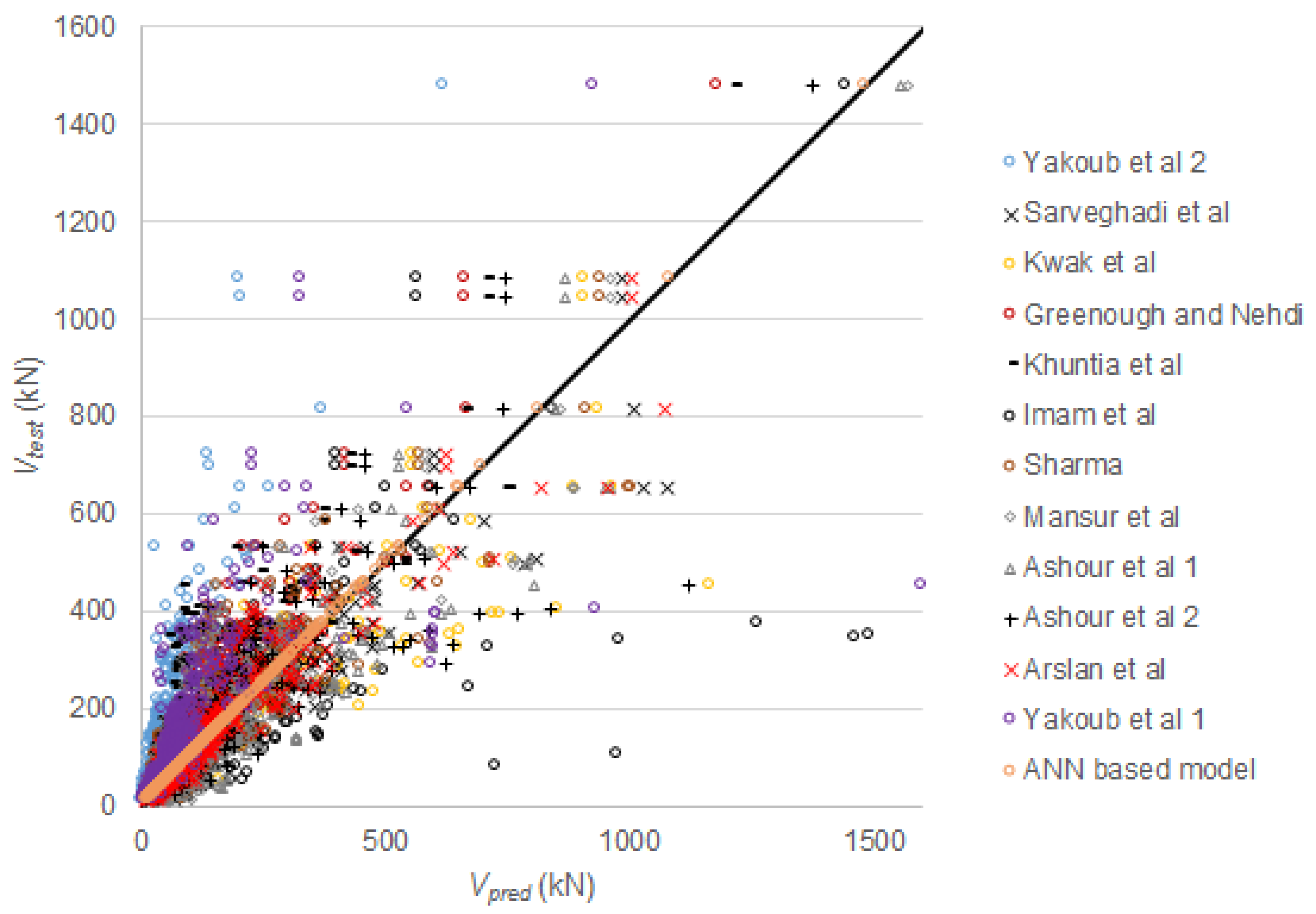
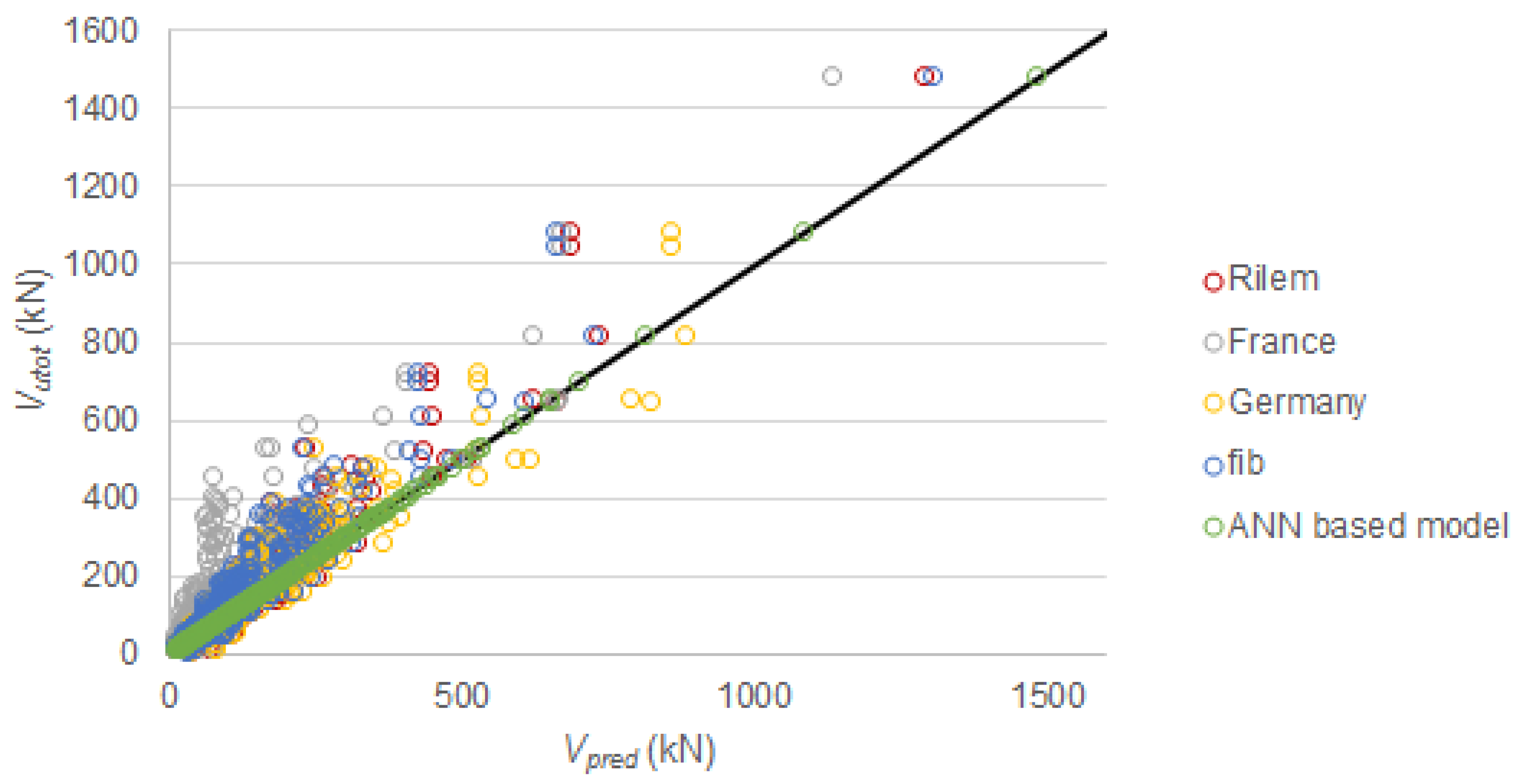
In this section, we compare the ANN-based model and the existing methods introduced in Table 1. The results of the ANN-based model are reported in [107]. The comparison between the experimental results and the existing methods are repeated here from [114]. Figure 8 shows the comparison between the existing methods proposed in the literature and our proposed model and the experimental results from the database. Figure 9 shows the comparison based on the existing code models. Table 8 gives the statistical results of Vutot/Vpred for all methods from Table 1 as well as our proposed model. The statistical properties of Vutot/Vpred result from all experimental results, and thus cover experiments on beams with a short shear span and slender beams. In [20], the analysis is further subdivided to evaluate the existing expressions for only slender beams, since expressions that did not include the enhancement factor for short shear spans will result in overly conservative predictions for beams with short shear spans. However, the overall conclusions regarding scatter on the results remains as discussed here.
From the presented results, we can conclude that our proposed model is a significant improvement as compared to the existing methods for determining the shear capacity of SFRC concrete members without shear reinforcement, for the dataset used in this study. The reason for this improvement is that our proposed model uses the available information from the literature in an optimal way. Moreover, comparing the predictions with our model to the model by Greenough and Nehdi [24] and Sarveghadi et al. [22], which were also based on soft computing methods, shows that using a larger database and evaluating a large number of ANN features results in a significant better fit of the experimental data.
4. Discussion
An important step is developing the proposed ANN-based expression was the selection of variables. While the initial data collection [20] focused on gathering as much information from the experiments as possible, it is not desirable to use all possible input values to develop the ANN-based expressions. Doing so increases the computational time of the algorithm that evaluates all 15 ANN features to find the optimal neural net. To select input variables, we included a number of dimensionless values, such as the clear shear span to depth ratio av/d, the reinforcement ratio ρ, and the fiber factor F. These inputs can take into account the combined effect of different parameters, and are more widely applicable since they are dimensionless. The factor av/d is the clear span to depth ratio, which takes into account the enhancement of the shear capacity due to direct load transfer for loads close to the support [115,116]. In addition, the clear shear span av, which is taken from the face of the loading plate to the face of the support, takes into account the dimensions of the support and the loading plate [117,118]. Moreover, from earlier shear research it was concluded that the distance that should be considered in the shear span to depth ratio is the clear shear span av and not the shear span a [119].
The reinforcement ratio ρ is the dimensionless equivalent of the area of longitudinal steel As. As a dimensionless parameter it allows to include a wider range of possible reinforcement layouts. The influence of the longitudinal steel needs to be considered as an input for a model for the shear capacity of SFRC, because the longitudinal steel resists shear through dowel action [120,121,122,123,124].
The fiber factor F [125,126,127,128] takes into account the geometry of the fibers (length and diameter) [53,129], the amount of fibers (fiber volume fraction) [69,70,130], and the bond properties of the fibers, which depends on the fiber type [4,131,132,133]. A challenge here was to ascribe bond properties to the less common fiber types that were encountered in the literature. Especially from older references [80,81,86], in which researchers were experimenting with many different fiber types, the fiber bond had to be estimated.
As mentioned before, the proposed model is limited to the ranges of the variables used for developing the model. These ranges are given in Table 2. While we can see that the experiments considered in the database cover a wide range for all material properties of the concrete [96,134], mild steel reinforcement [74,75], and fibers [135], the range of heights of specimens tested in the literature (expressed in Table 2 based on the effective depth d) is limited. We can see that the maximum effective depth in the experiments is 1118 mm. The number of specimens with an effective depth of d ≥ 600 mm for the considered dataset is 20 experiments on a total of 430 datapoints. As such, only 4.7% of the data from the literature considers realistic and large sizes of beams. All other specimens are laboratory-sized specimens. This finding underlines the need for further experiments on large SFRC beams failing in shear. The need for large-sized beams is especially important given the fact that the size effect in shear affects the shear capacity of large members. The size effect in shear [104,105,106,136,137] is the effect observed in experiments where the shear stress at failure decreases as the member height increases. The cause of the size effect is still under discussion. For SFRC, there is a discussion on whether or not the size effect in shear occurs as well [2,138]. Since the number of experiments on large beams is limited, and the size effect in shear in SFRC may be related to the amount of fibers (or fiber factor), further research is needed on this topic. Given the lack of data in this regard, we may need to reevaluate our proposed model when further experimental results on larger-sized beams become available.
Since the proposed ANN-based model simulates the experimental results with a very good fit, parameter studies with the ANN-based model give the same result as parameter studies with the original data. Such parameter studies were carried out earlier [20]. The outcome of these parameter studies can be summarized as follows:
With our proposed model, which can simulate well the available experimental results, the following practical applications are possible: the model can be used to prepare further laboratory studies, the model can be used for comparison to mechanical models, and the model can be used to predict the shear capacity of structural elements for design purposes, provided that the input parameters are within the specified ranges from Table 2. One of the main advantages of the proposed model as compared to other numerical approaches is the short amount of time required to obtain the prediction of the shear capacity. As can be seen in Table 7, the computation time is less than 0.1 millisecond. Therefore, compared to nonlinear finite element models, the proposed method is very fast.
At this moment, a theory that predicts the shear capacity of SFRC elements without mild steel shear reinforcement based on the different shear-carrying mechanisms is not available yet. Given the lack of theoretical understanding of the problem under study, our ANN-based proposed model can bridge the gap and give an optimal prediction based on the available data. However, research on the shear-carrying mechanisms in SFRC is still necessary to understand the actual mechanics of the problem.
5. Conclusions
This paper proposes a neural networks-based method to predict the shear capacity of SFRC elements without mild steel shear reinforcement based on the available data in the literature. To derive the ANN-based expression, we did the following:
- We used a database with 430 datapoints from the literature.
- For the analysis, we selected nine input parameters related to the geometry, properties of the concrete, the flexural steel reinforcement, and the fibers, and one output parameter, the maximum sectional shear force caused by the applied load in the experiment and self-weight of the beam.
- To find the optimal ANN-based model, different combinations of 15 features of ANN models were analyzed.
- The optimal model resulted in a maximum error of 0% and a mean relative error of 0.0% for the 430 datapoints, respectively.
The main advantages of our proposed model and the main outcomes of this study are:
- Our proposed model outperforms the available models and expressions for the shear capacity of SFRC.
- Our model can be used to prepare experiments, for design (within the input parameter ranges), and to support further development of mechanical models through robust parameter studies.
- The computational time of a datapoint with our model is less than 0.1 millisecond.
The limitations of the proposed model are as follows:
- The proposed model can only be used for the ranges of the variables available in the dataset.
- The model does not cover large-sized beams as a result of a lack of data on such specimens. As such, we recommend further experiments on large SFRC beams failing in shear and further studies on the size effect in SFRC.
- This study does not answer the question about the mechanics underlying the problem of shear in SFRC, but we can explore various influences with parametric studies using our proposed ANN-based model. Our model also facilitates the evaluation and improvement of existing and future mechanical models, based on the currently available experimental results.
Author Contributions
Conceptualization, M.A. and E.O.L.L.; methodology, M.A. and E.O.L.L.; software, M.A.; validation, M.A. and E.O.L.L.; formal analysis, M.A. and E.O.L.L.; investigation, M.A. and E.O.L.L.; resources, M.A. and E.O.L.L.; data curation, M.A. and E.O.L.L.; writing—original draft preparation, M.A. and E.O.L.L.; writing—review and editing, M.A. and E.O.L.L.; visualization, M.A. and E.O.L.L.; supervision, M.A. and E.O.L.L.; project administration, E.O.L.L.; funding acquisition, M.A. and E.O.L.L.
Funding
This research was funded by the program of Collaboration Grants 2019 of Universidad San Francisco de Quito. The APC was covered through the Open Access fund of Delft University of Technology.
Conflicts of Interest
The authors declare no conflict of interest.
Abbreviations
| a | shear span |
| av | clear shear span |
| b | bias |
| bw | web width |
| c | height of compression zone |
| d | effective depth |
| da | maximum aggregate size |
| df | fiber diameter |
| dv | shear depth |
| e | factor to take effect of shear span to depth ratio into account |
| fc’ | specified concrete compressive strength |
| fc,cube | average measured concrete cube compressive strength |
| fc,cyl | average measured concrete cylinder compressive strength |
| characteristic value of post-cracking flexural strength for a deflection of 3.5 mm | |
| fck | characteristic concrete cylinder compressive strength |
| fctk | characteristic tensile strength of concrete |
| uniaxial tensile strength of SFRC | |
| fcuf | cube compressive strength of fiber-reinforced concrete |
| fFtuk | characteristic value of post-cracking strength for ultimate crack opening |
| fRk,4 | characteristic residual flexural strength for the ultimate limit state at a CMOD (crack mouth opening displacement) of 3.5 mm |
| fspfc | splitting tensile strength of fiber-reinforced concrete |
| ft’ | specified tensile strength of concrete mix |
| ftenf | tensile strength of the fibers |
| fy | yield strength of the reinforcement steel |
| h | height of cross-section |
| hf | height of flange |
| k | size effect factor |
| kf | factor that considers the contribution of flanges in T-sections (= 1 for rectangular sections) |
| factor that considers the orientation of the fibers | |
| size factor, which accounts for the fact that fibers are better distributed in larger elements | |
| lf | fiber length |
| lspan | span length |
| ltot | total specimen length |
| n | parameter for effect of geometry of flanged sections |
| pt | amount of training examples |
| ptt | amount of testing examples |
| pv | amount of validation examples |
| q | value of row |
| rf | fiber radius |
| sx | crack spacing |
| sxe | equivalent crack spacing factor |
| vmax | shear stress at maximum sectional shear Vmax |
| wlim | limiting crack width |
| wmax | maximum crack width permitted by the code |
| wu | ultimate crack width, i.e., the value attained at the Ultimate Limit State for resistance to combined stresses on the outer fiber under the moment exerted in this section |
| vb | shear strength attributed to fibers |
| z | internal lever arm |
| effective area bw × d, with d limited to 1.5 m | |
| Af | cross-sectional area of the fiber |
| As | area of longitudinal tension reinforcement |
| Avf | shear area over which fibers contribute |
| CRd,c | calibration factor for the design shear capacity |
| Ef | modulus of elasticity of the fibers |
| Es | modulus of elasticity of reinforcement steel |
| F | fiber factor |
| Gm | matrix shear modulus |
| K | orientation coefficient |
| M | sectional moment |
| P | sum of all datapoints |
| Pmax | maximum load in experiment |
| R | Pearson Correlation Coefficient |
| Rg | geometry factor from Yakoub [31]: 0.83 for crimped fibers, 1.00 for hooked fibers, and 0.91 for round fibers |
| S | fiber spacing |
| V | sectional shear force |
| Vc | concrete contribution to shear capacity |
| Vcd | design value of concrete contribution to shear capacity |
| Vf | fiber volume fraction |
| Vfd | design value of fiber contribution to shear capacity |
| Vmax | maximum sectional shear in experiment caused by applied load only (without self-weight) |
| Vmin | lower bound to the shear capacity |
| Vpred | predicted shear capacity |
| VRd | design shear capacity |
| VRd,c | design shear capacity of the concrete contribution |
| design shear capacity of fiber-reinforced concrete | |
| VRd,cf | design shear capacity of the fiber contribution, notation used in German guideline |
| VRd,c,min | lower bound to the design shear capacity of the concrete contribution |
| VRd,f | design shear capacity of the steel fiber contribution |
| Vu | ultimate shear capacity |
| Vutot | experimental shear capacity, including contribution from self-weight |
| W | synaptic weight |
| factor that accounts for the long-term effects | |
| β | fiber and matrix property factor developed by Cox [146] |
| γc | concrete material factor |
| γcf | concrete material factor, notation used in French guideline |
| partial factor for tensile strength of fiber-reinforced concrete | |
| γE | additional safety factor |
| εel | elastic strain |
| εlim | limiting strain |
| εmax | maximum strain |
| εu | ultimate strain at the ULS for bending combined with axial forces on the outer fiber under the moment exerted in the section |
| εx | strain at mid-depth of the cross-section |
| ηo | fiber orientation factor = 0.41 for fibers with a 3D random orientation, as derived by Romualdi and Mandel [147], but can be larger for members with thin webs |
| ηl | a length factor used to account for the variability in the fiber embedment length across the cracking plane |
| θ | angle of compression strut |
| ξ | size effect factor from Bažant and Kim [106] |
| ρ | reinforcement ratio |
| ρf | fiber bond factor: 0.5 for straight fibers, 0.75 for crimped fibers, 1 for hooked fibers |
| σRd,f | residual tensile strength of fiber-reinforced cross-section |
| σf(ε) | experimentally determined relation between stress in fiber concrete and strain |
| σf(w) | experimentally determined relation between post-cracking stress and crack width w |
| σtu | average stress at the ultimate limit state in the equivalent tensile stress block used for bending moment analysis of SFRC |
| τ | bond strength between fibers and matrix |
| τfd | design value of bond strength between fibers and matrix |
| ψ | size effect factor from Imam et al. [30] |
| ω | reinforcement ratio that includes the effect of fibers |
References
- Amin, A.; Foster, S.J.; Watts, M. Modelling the tension stiffening effect in SFR-RC. Mag. Concr. Res. 2016, 68, 339–352. [Google Scholar] [CrossRef]
- Lantsoght, E.O.L. How do steel fibers improve the shear capacity of reinforced concrete beams without stirrups? Compos. Part B Eng. 2019, 175, 107079. [Google Scholar] [CrossRef]
- Singh, B.; Jain, K. An appraisal of steel fibers as minimum shear reinforcement in concrete beams (with Appendix). ACI Struct. J. 2014, 111. [Google Scholar] [CrossRef]
- Kim, K.S.; Lee, D.H.; Hwang, J.-H.; Kuchma, D.A. Shear behavior model for steel fiber-reinforced concrete members without transverse reinforcements. Compos. Part B Eng. 2012, 43, 2324–2334. [Google Scholar] [CrossRef]
- Stevens, D.J.; Liu, D. Constitutive Modeling of Fiber Reinforced Concrete. ACI Spec. Publ. 1994, 142. [Google Scholar] [CrossRef]
- Lee, S.-C.; Cho, J.-Y.; Vecchio, F.J. Analysis of Steel Fiber-Reinforced Concrete Elements Subjected to Shear. ACI Struct. J. 2016, 113. [Google Scholar] [CrossRef]
- Minelli, F.; Vecchio, F.J. Compression Field Modeling of Fiber-Reinforced Concrete Members Under Shear Loading. ACI Struct. J. 2006, 103. [Google Scholar] [CrossRef]
- Vecchio, F.J. Disturbed stress field model for reinforced concrete: Formulation. J. Struct. Eng. ASCE 2000, 126, 1070–1077. [Google Scholar] [CrossRef]
- Susetyo, J.; Gauvreau, P.; Vecchio, F.J. Steel Fiber-Reinforced Concrete Panels in Shear: Analysis and Modeling. ACI Struct. J. 2013, 110. [Google Scholar] [CrossRef]
- Matthys, S.; Soetens, T. Engineering Model for SFRC Shear Strength Based on MC2010 MCFT Approach. In Proceedings of the Fib Symposium 2017, Maastricht, The Netherlands, 12–24 June 2017. [Google Scholar]
- Barros, J.A.O.; Foster, S.J. An integrated approach for predicting the shear capacity of fibre reinforced concrete beams. Eng. Struct. 2018, 174, 346–357. [Google Scholar] [CrossRef] [Green Version]
- Foster, S.J.; Agarwal, A.; Amin, A. Design of steel fiber reinforced concrete beams for shear using inverse analysis for determination of residual tensile strength. Struct. Concr. 2018, 19, 129–140. [Google Scholar] [CrossRef]
- Lee, D.H.; Kim, K.S.; Han, S.J.; Zhang, D.; Kim, J. Dual potential capacity model for reinforced concrete short and deep beams subjected to shear. Struct. Concr. 2018, 19, 76–85. [Google Scholar] [CrossRef] [Green Version]
- Lee, D.H.; Han, S.-J.; Kim, K.S.; LaFave, J.M. Shear capacity of steel fiber-reinforced concrete beams. Struct. Concr. 2017, 18, 278–291. [Google Scholar] [CrossRef]
- Batson, G.B.; Youssef, A.G. Shear Capacity of Fiber Reinforced Concrete Based on Plasticity of Concrete: A Review. ACI Spec. Publ. 1994, 142. [Google Scholar] [CrossRef]
- Spinella, N. Shear strength of full-scale steel fibre-reinforced concrete beams without stirrups. Comput. Concr. 2013, 11, 365–382. [Google Scholar] [CrossRef]
- Lim, T.Y.; Paramasivam, P.; Lee, S.L. Shear and moment capacity of reinforced steel-fibre-concrete beams. Mag. Concr. Res. 1987, 39, 148–160. [Google Scholar] [CrossRef]
- Lim, T.Y.; Paramasivam, P.; Lee, S.L. Analytical Model for Tensile Behavior of Steel-Fiber Concrete. ACI Mater. J. 1987, 84. [Google Scholar] [CrossRef]
- Narayanan, R.; Kareem-Palanjian, A.S. Effect of Fibre Addition on Concrete Strengths. Indian Concr. J. 1984, 58, 100–103. [Google Scholar]
- Lantsoght, E.O.L. Database of Shear Experiments on Steel Fiber Reinforced Concrete Beams without Stirrups. Materials 2019, 12, 917. [Google Scholar] [CrossRef]
- Conforti, A.; Minelli, F. Compression field modelling of fibre reinforced concrete shear critical deep beams: A numerical study. Mater. Struct. 2016, 49, 3369–3383. [Google Scholar] [CrossRef]
- Sarveghadi, M.; Gandomi, A.H.; Bolandi, H.; Alavi, A.H. Development of prediction models for shear strength of SFRCB using a machine learning approach. Neural Comput. Appl. 2015. [Google Scholar] [CrossRef]
- Kwak, Y.-K.; Eberhard, M.O.; Kim, W.-S.; Kim, J. Shear Strength of Steel Fiber-Reinforced Concrete Beams without Stirrups. ACI Struct. J. 2002, 99. [Google Scholar] [CrossRef]
- Greenough, T.; Nehdi, M. Shear Behavior of Fiber-Reinforced Self-Consolidating Concrete Slender Beams. ACI Mater. J. 2008, 105. [Google Scholar] [CrossRef]
- Khuntia, M.; Stojadinovic, B.; Goel, S.C. Shear Strength of Normal and High-Strength Fiber Reinforced Concrete Beams without Stirrups. ACI Struct. J. 1999, 96. [Google Scholar] [CrossRef]
- Sharma, A.K. Shear Strength of Steel Fiber Reinforced Concrete Beams. ACI J. Proc. 1986, 83. [Google Scholar] [CrossRef]
- Mansur, M.A.; Ong, K.C.G.; Paramasivam, P. Shear Strength of Fibrous Concrete Beams Without Stirrups. J. Struct. Eng. 1986, 112, 2066–2079. [Google Scholar] [CrossRef]
- Ashour, S.A.; Hasanain, G.S.; Wafa, F.F. Shear Behavior of High-Strength Fiber Reinforced Concrete Beams. ACI Struct. J. 1992, 89. [Google Scholar] [CrossRef]
- Arslan, G. Shear strength of Steel Fiber Reinforced Concrete (SFRC) slender beams. KSCE J. Civ. Eng. 2014, 18, 587–594. [Google Scholar] [CrossRef]
- Imam, M.; Vandewalle, L.; Mortelmans, F.; Van Gemert, D. Shear domain of fibre-reinforced high-strength concrete beams. Eng. Struct. 1997, 19, 738–747. [Google Scholar] [CrossRef]
- Yakoub, H.E. Shear Stress Prediction: Steel Fiber-Reinforced Concrete Beams without Stirrups. ACI Struct. J. 2011, 108. [Google Scholar] [CrossRef]
- Association Française de Génie Civil. Bétons Fibrés à Ultra-Hautes Performances: Recommandations; Association Française de Génie Civil: Paris, France, 2013; p. 359. [Google Scholar]
- DAfStB. DAfStB-Richtlinie Stahlfaserbeton; DIN: Berlin, Germany, 2012; p. 47.
- RILEM TC 162-TDF. σ-ε-Design Method. Mater. Struct. 2003, 36, 560–567. [CrossRef]
- FIB. Model Code 2010: Final Draft; International Federation for Structural Concrete: Lausanne, Switzerland, 2012; p. 676. [Google Scholar]
- CNR—Advisory Committee on Technical Recommendations for Construction. Guide for the Design and Construction of Fiber-Reinforced Concrete Structures: CNR-DT 204/2006; CNR: Rome, Italy, 2007; p. 57.
- Hertzmann, A.; Fleet, D. Machine LearningData Mining, Lecture Notes CSC 411/D11; Computer Science Department, University of Toronto: Toronto, ON, Canada, 2012. [Google Scholar]
- Basheer, I.A.; Hajmeer, M. Artificial neural networks: Fundamentals, computing, design, and application. J. Microbiol. Methods 2000, 43, 3–31. [Google Scholar] [CrossRef]
- McCulloch, W.S.; Pitts, W. A logical calculus of the ideas immanent in nervous activity. Bull. Biophys. 1943, 5, 115–133. [Google Scholar] [CrossRef]
- Hern, A. Google Says Machine Learning Is the Future. So I Tried it Myself. Available online: https://www.theguardian.com/technology/2016/jun/28/google-says-machine-learning-is-the-future-so-i-tried-it-myself (accessed on 2 November 2016).
- Flood, I. Towards the next generation of artificial neural networks for civil engineering. Adv. Eng. Inform. 2008, 22, 4–14. [Google Scholar] [CrossRef]
- Hossain, K.M.A.; Gladson, L.R.; Anwar, M.S. Modeling shear strength of medium- to ultra-high-strength steel fiber-reinforced concrete beams using artificial neural network. Neural Comput. Appl. 2016. [Google Scholar] [CrossRef]
- Kara, I.F. Empirical modeling of shear strength of steel fiber reinforced concrete beams by gene expression programming. Neural Comput. Appl. 2013, 23, 823–834. [Google Scholar] [CrossRef]
- Cuenca, E.; Conforti, A.; Minelli, F.; Plizzari, G.A.; Navarro Gregori, J.; Serna, P. A material-performance-based database for FRC and RC elements under shear loading. Mater. Struct. 2018, 51, 11. [Google Scholar] [CrossRef]
- Sahoo, D.R.; Sharma, A. Effect of Steel Fiber Content on Behavior of Concrete Beams with and without Stirrups. ACI Struct. J. 2014, 111, 1157–1166. [Google Scholar] [CrossRef]
- Shoaib, A.; Lubell, A.S.; Bindiganavile, V.S. Shear response of lightweight steel fiber reinforced concrete members without stirrups. Mater. Struct. 2015, 48, 3141–3157. [Google Scholar] [CrossRef]
- Sathya, S.; Sylviya, B. Shear strength of high-strength steel fibre reinforced concrete rectangular beams. Int. J. Civ. Eng. Technol. 2017, 8, 1716–1729. [Google Scholar]
- Arslan, G.; Keskin, R.S.O.; Ulusoy, S. An experimental study on the shear strength of SFRC beams without stirrups. J. Theor. Appl. Mech. 2017, 55, 1205. [Google Scholar] [CrossRef]
- Parra-Montesinos, G.J.; Wight, J.K.; Dinh, H.H.; Libbrecht, A.; Padilla, C. Shear Strengthfiber Reinforced Concrete Beams Without Stirrups; University of Michigan: Ann Arbor, MI, USA, 2006; p. 39. [Google Scholar]
- Rosenbusch, J.; Teutsch, M. Trial Beams in Shear Brite/Euram Project 97-4163 Final Rep. Sub Task 4.2; Technical University of Braunschweig: Braunschweig, Germany, 2003; pp. 105–117. [Google Scholar]
- Sahoo, D.R.; Bhagat, S.; Reddy, T.C.V. Experimental study on shear-span to effective-depth ratio of steel fiber reinforced concrete T-beams. Mater. Struct. 2016, 49, 3815–3830. [Google Scholar] [CrossRef]
- Amin, A.; Foster, S.J. Shear strength of steel fibre reinforced concrete beams with stirrups. Eng. Struct. 2016, 111, 323–332. [Google Scholar] [CrossRef]
- Tahenni, T.; Chemrouk, M.; Lecompte, T. Effect of steel fibers on the shear behavior of high strength concrete beams. Constr. Build. Mater. 2016, 105, 14–28. [Google Scholar] [CrossRef]
- Narayanan, R.; Darwish, I.Y.S. Use of Steel Fibers as Shear Reinforcement. ACI Struct. J. 1987, 84. [Google Scholar] [CrossRef]
- Cucchiara, C.; La Mendola, L.; Papia, M. Effectiveness of stirrups and steel fibres as shear reinforcement. Cem. Concr. Compos. 2004, 26, 777–786. [Google Scholar] [CrossRef]
- Lim, D.H.; Oh, B.H. Experimental and theoretical investigation on the shear of steel fibre reinforced concrete beams. Eng. Struct. 1999, 21, 937–944. [Google Scholar] [CrossRef]
- Dinh, H.H.; Parra-Montesinos, G.J.; Wight, J.K. Shear Behavior of Steel Fiber-Reinforced Concrete Beams without Stirrup. Reinforcement. ACI Struct. J. 2010, 107. [Google Scholar] [CrossRef]
- Lima Araujo, D.; Tibúrcio Nunes, F.G.; Toledo Filho, R.D.; Souza de Andrade, M.A. Shear strength of steel fiber-reinforced concrete beams. Acta Sci. 2014, 36, 389–397. [Google Scholar] [CrossRef]
- Casanova, P.; Rossi, P.; Schaller, l. Can Steel Fibers Replace Transverse Reinforcements in Reinforced Concrete Beams? ACI Mater. J. 1997, 94. [Google Scholar] [CrossRef]
- Aoude, H.; Belghiti, M.; Cook, W.D.; Mitchell, D. Response of Steel Fiber-Reinforced Concrete Beams with and without Stirrups. ACI Struct. J. 2012, 109. [Google Scholar] [CrossRef]
- Minelli, F.; Plizzari, G.A. On the Effectiveness of Steel Fibers as Shear Reinforcement. ACI Struct. J. 2013, 110. [Google Scholar] [CrossRef]
- Kang, T.H.-K.; Kim, W.; Kwak, Y.-K.; Hong, S.-G. Shear Testing of Steel Fiber-Reinforced Lightweight Concrete Beams without Web Reinforcement. ACI Struct. J. 2011, 108. [Google Scholar] [CrossRef]
- Casanova, P.; Rossi, P. High-Strength Concrete Beams Submitted to Shear: Steel Fibers Versus Stirrups. ACI Spec. Publ. 1999, 182. [Google Scholar] [CrossRef]
- Zarrinpour, M.R.; Chao, S.-H. Shear Strength Enhancement Mechanisms of Steel Fiber-Reinforced Concrete Slender Beams. ACI Struct. J. 2017, 114. [Google Scholar] [CrossRef]
- Noghabai, K. Beams of Fibrous Concrete in Shear and Bending: Experiment and Model. J. Struct. Eng. 2000, 126, 243–251. [Google Scholar] [CrossRef]
- Randl, N.; Mészöly, T.; Harsányi, P. Shear Behaviour of UHPC Beams with Varying Degrees of Fibre and Shear Reinforcement. In Proceedings of the Fib Symposium 2017, Maastricht, The Netherlands, 12–14 June 2017. [Google Scholar]
- Tan, K.H.; Murugappan, K.; Paramasivam, P. Shear Behavior of Steel Fiber Reinforced Concrete Beams. ACI Struct. J. 1993, 90. [Google Scholar] [CrossRef]
- Pansuk, W.; Nguyen, T.N.; Sato, Y.; Den Uijl, J.A.; Walraven, J.C. Shear capacity of high performance fiber reinforced concrete I-beams. Constr. Build. Mater. 2017, 157, 182–193. [Google Scholar] [CrossRef]
- Kim, C.-G.; Lee, H.; Park, H.-G.; Hong, G.-H.; Kang, S.-M. Effect of Steel Fibers on Minimum Shear Reinforcement of High-Strength Concrete Beams. ACI Struct. J. 2017, 114. [Google Scholar] [CrossRef]
- Narayanan, R.; Darwish, I.Y.S. Fiber Concrete Deep. Beams in Shear. ACI Struct. J. 1988, 85. [Google Scholar] [CrossRef]
- Li, V.C.; Ward, R.; Hamza, A.M. Steel and Synthetic Fibers as Shear Reinforcement. ACI Mater. J. 1992, 89. [Google Scholar] [CrossRef] [Green Version]
- Swamy, R.N.; Jones, R.; Chiam, A.T.P. Influence of Steel fibers on the Shear Resistance of Lightweight Concrete I-Beams. ACI Struct. J. 1993, 90. [Google Scholar] [CrossRef]
- Cho, S.-H.; Kim, Y.I.L. Effects of Steel Fibers on Short Beams Loaded in Shear. ACI Struct. J. 2003, 100. [Google Scholar] [CrossRef]
- Kang, T.H.-K.; Kim, W.; Massone, L.M.; Galleguillos, T.A. Shear-Flexure Coupling Behavior of Steel Fiber-Reinforced Concrete Beams. ACI Struct. J. 2012, 109. [Google Scholar] [CrossRef]
- Dupont, D.; Vandewalle, L. Shear Capacity of Concrete Beams Containing Longitudinal Reinforcement and Steel Fibers. ACI Spec. Publ. 2003, 216. [Google Scholar] [CrossRef]
- Dupont, D. Modelling and Experimental Validation of the Constitutive Law (σ-ε) and Cracking Behaviour of Steel Fibre Reinforced Concrete; KU Leuven: Leuven, Belgium, 2003. [Google Scholar]
- Kal, K.W.; Lee, D.H.; Bang, Y.S.; Cho, H.C.; Kang, J.O.; Kim, K.S. The Effectiveness of Steel Fibers as Shear Reinforcement. Concr. Int. 1985, 7, 59–60. [Google Scholar]
- Batson, G.; Jenkins, E.; Spatney, R. Steel Fibers as Shear Reinforcement in Beams. ACI J. Proc. 1972, 69. [Google Scholar] [CrossRef]
- Zhao, J.; Liang, J.; Chu, L.; Shen, F. Experimental Study on Shear Behavior of Steel Fiber Reinforced Concrete Beams with High-Strength Reinforcement. Materials 2018, 11, 1682. [Google Scholar] [CrossRef]
- Jindal, R.L. Shear and Moment Capacities of Steel Fiber Reinforced Concrete Beams. ACI Spec. Publ. 1984, 81. [Google Scholar] [CrossRef]
- Shin, S.-W.; Oh, J.-G.; Ghosh, S.K. Shear Behavior of Laboratory-Sized High-Strength Concrete Beams Reinforced With Bars and Steel Fibers. ACI Spec. Publ. 1994, 142. [Google Scholar] [CrossRef]
- Imam, M.; Vandewalle, L.; Mortelmans, F. Shear Capacity of Steel Fiber High-Strength Concrete Beams. ACI Spec. Publ. High Perform. Concr. 1994, 149. [Google Scholar] [CrossRef]
- Imam, M.; Vandewalle, L. Role of Fibers in Controlling Failure Modes of High-Strength Concrete Beams. Spec. Publ. 2000, 193. [Google Scholar] [CrossRef]
- Huang, C.-K.; Zhang, H.Z.; Guan, Z.G. Experimental Study on Shear Resistance of Steel Fiber Reinforced High-Strength Concrete Beams. ACI Spec. Publ. 2005, 228. [Google Scholar] [CrossRef]
- Kwak, K.-H.; Suh, J.; Hsu, C.-T.T. Shear-Fatigue Behavior of Steel Fiber Reinforced Concrete Beams. ACI Struct. J. 1991, 88. [Google Scholar] [CrossRef]
- Roberts, T.M.; Ho, N.L. Shear failure of deep fibre reinforced concrete beams. Int. J. Cem. Compos. Lightweight Concr. 1982, 4, 145–152. [Google Scholar] [CrossRef]
- Hwang, J.-H.; Lee, D.H.; Kim, K.S.; Ju, H.; Seo, S.-Y. Evaluation of shear performance of steel fibre reinforced concrete beams using a modified smeared-truss model. Mag. Concr. Res. 2013, 65, 283–296. [Google Scholar] [CrossRef]
- Spinella, N.; Colajanni, P.; Mendola, L.L. Nonlinear Analysis of Beams Reinforced in Shear with Stirrups and Steel Fibers. ACI Struct. J. 2012, 109. [Google Scholar] [CrossRef]
- Chalioris, C.E.; Sfiri, E.F. Shear Performance of Steel Fibrous Concrete Beams. Procedia Eng. 2011, 14, 2064–2068. [Google Scholar] [CrossRef] [Green Version]
- Cohen, M.; Aoude, H. Shear behavior of SFRC and SCFRC beams. In Proceedings of the 3rd International Structural Specialty Conference, Edmonton, AB, Canada, 6–9 June 2012. [Google Scholar]
- Aoude, H.; Cohen, M. Shear response of SFRC beams constructed with SCC and Steel Fibers. Electron. J. Struct. Eng. 2014, 14, 71–83. [Google Scholar]
- Qissab, M.; Salman, M.M. Shear strength of non-prismatic steel fiber reinforced concrete beams without stirrups. Struct. Eng. Mech. 2018, 67, 347–358. [Google Scholar]
- Furlan, S.; de Hanai, J.B. Shear behaviour of fiber reinforced concrete beams. Cem. Concr. Compos. 1997, 19, 359–366. [Google Scholar] [CrossRef]
- Dancygier, A.N.; Savir, Z. Effects of Steel Fibers on Shear Behavior of High-Strength Reinforced Concrete Beams. Adv. Struct. Eng. 2011, 14, 745–761. [Google Scholar] [CrossRef]
- Krassowska, J.; Kosior-Kazberuk, M. Failure mode in shear of steel fiber reinforced concrete beams. MATEC Web Conf. 2018, 163, 02003. [Google Scholar] [CrossRef]
- Yoo, D.-Y.; Yang, J.-M. Effects of stirrup, steel fiber, and beam size on shear behavior of high-strength concrete beams. Cem. Concr. Compos. 2018, 87, 137–148. [Google Scholar] [CrossRef]
- Gali, S.; Subramaniam, K.V.L. Shear behavior of steel fiber reinforced concrete using full-field displacements from digital image correlation. MATEC Web Conf. 2017, 120, 04003. [Google Scholar] [CrossRef]
- Zamanzadeh, Z.; Lourenço, L.; Barros, J. Recycled Steel Fibre Reinforced Concrete failing in bending and in shear. Constr. Build. Mater. 2015, 85, 195–207. [Google Scholar] [CrossRef] [Green Version]
- Shoaib, A.; Lubell, A.S.; Bindiganavile, V.S. Size Effect in Shear for Steel Fiber-Reinforced Concrete Members without Stirrups. ACI Struct. J. 2014, 111, 1081–1089. [Google Scholar] [CrossRef]
- Shoaib, A. Shear in Steel Fiber Reinforced Concrete without Stirrups; University of Alberta: Edmonton, AB, Canada, 2012. [Google Scholar]
- Bae, B.I.; Choi, H.K.; Choi, C.S. Flexural and Shear Capacity Evaluation of Reinforced Ultra-High Strength Concrete Members with Steel Rebars. Key Eng. Mater. 2014, 577, 17–20. [Google Scholar] [CrossRef]
- Abdul-Zaher, A.S.; Abdul-Hafez, L.M.; Tawfic, Y.R.; Hammed, O. Shear behavior of fiber reinforced concrete beams. J. Eng. Sci. Assiut Univ. 2016, 44, 132–144. [Google Scholar]
- Ruiz, M.F.; Muttoni, A. Size effect in shear and punching shear failures of concrete members without transverse reinforcement: Differences between statically determinate members and redundant structures. Struct. Concr. 2018, 19, 65–75. [Google Scholar] [CrossRef]
- Bazant, Z.P.; Kazemi, M.T. Size effect on Diagonal Shear Failure of Beams without Stirrups. ACI Struct. J. 1991, 88, 268–276. [Google Scholar]
- Shioya, T.; Iguro, M.; Nojiri, Y.; Akiyama, H.; Okada, T. Shear strength of large reinforced concrete beams. Fract. Mech. Appl. Concr. 1989, 118, 259–279. [Google Scholar]
- Bazant, Z.P.; Kim, J.K. Size Effect in Shear Failure of Longitudinally Reinforced Beams. J. Am. Concr. Inst. 1984, 81, 456–468. [Google Scholar]
- Developer. SFRC Dataset + Target vs. Output [Data Set]; Zenodo: Genève, Switzerland, 2019. [Google Scholar] [CrossRef]
- Haykin, S.S. Neural Networks Learning Machines, 3rd ed.; Prentice Hall/Pearson: New York, NY, USA, 2009; p. 906. [Google Scholar]
- Abambres, M.; Lantsoght, E.O.L. Neural network-based formula for shear capacity prediction of one-way slabs under concentrated loads. engrXiv 2018, 1–33. [Google Scholar] [CrossRef]
- The Mathworks, I. Matlab R2017a, User’s Guide; MathWorks: Natick, MA, USA, 2017. [Google Scholar]
- Abambres, M. ANN Software Validation Report. Figshare. Available online: https://figshare.com/articles/ANNSoftwareValidation-Report_pdf/6962873 (accessed on 12 December 2018). [CrossRef]
- Abambres, M.; Marcy, M.; Doz, G. Potential of Neural Networks for Structural Damage Localization. ACI Av. Cienc. Ing. 2019, 11. [Google Scholar] [CrossRef]
- Developer. W and b Arrays [Data Set]; Zenodo: Genève, Switzerland, 2019. [Google Scholar] [CrossRef]
- Lantsoght, E. Database of Experiments on SFRC Beams without Stirrups Failing in Shear, 1st ed.; Zenodo: Genève, Switzerland, 2019. [Google Scholar] [CrossRef]
- Reissen, K.; Classen, M.; Hegger, J. Shear in reinforced concrete slabs—Experimental investigations in the effective shear width of one-way slabs under concentrated loads and with different degrees of rotational restraint. Struct. Concr. 2018, 19, 36–48. [Google Scholar] [CrossRef]
- He, Z.-Q.; Liu, Z.; Ma, Z.J. Investigation of Load-Transfer Mechanisms in Deep. Beams and Corbels. ACI Struct. J. 2012, 109, 467–476. [Google Scholar]
- Shatarat, N.; Katkhuda, H.; Abdel-Jaber, M.; Alqam, M. Experimental investigation of reinforced concrete beams with spiral reinforcement in shear. Constr. Build. Mater. 2016, 125, 585–594. [Google Scholar] [CrossRef]
- Naik, U.; Kute, S. Span-to-depth ratio effect on shear strength of steel fiber-reinforced high-strength concrete deep beams using ANN model. Int. J. Adv. Struct. Eng. 2013, 5, 29. [Google Scholar] [CrossRef]
- Lantsoght, E.O.L.; van der Veen, C.; de Boer, A.; Walraven, J.C. Recommendations for the Shear Assessment of Reinforced Concrete Slab Bridges from Experiments. Struct. Eng. Int. 2013, 23, 418–426. [Google Scholar] [Green Version]
- Cladera, A.; Marí, A.; Bairán, J.M.; Ribas, C.; Oller, E.; Duarte, N. The compression chord capacity model for the shear design and assessment of reinforced and prestressed concrete beams. Struct. Concr. 2016, 17, 1017–1032. [Google Scholar] [CrossRef] [Green Version]
- Gastebled, O.J.; May, I.M. Fracture mechanics model applied to shear failure of reinforced concrete beams without stirrups. ACI Struct. J. 2001, 98, 184–190. [Google Scholar]
- Vintzileou, E. Shear transfer by dowel action and friction as related to size effects. CEB Bull. 1997, 237, 53–77. [Google Scholar]
- Millard, S.G.; Johnson, R.P. Shear transfer across cracks in reinforced concrete due to aggregate interlock and dowel action. Mag. Concr. Res. 1984, 36, 9–21. [Google Scholar] [CrossRef]
- Dulacska, H. Dowel Action of Reinforcement Crossing Cracks in Concrete. ACI J. Proc. 1972, 69, 754–757. [Google Scholar]
- Al-Musawi, A.A. Determination of shear strength of steel fiber RC beams: Application of data-intelligence models. Front. Struct. Civ. Eng. 2018. [Google Scholar] [CrossRef]
- Leone, M.; Centonze, G.; Colonna, D.; Micelli, F.; Aiello, M.A. Fiber-reinforced concrete with low content of recycled steel fiber: Shear behaviour. Constr. Build. Mater. 2018, 161, 141–155. [Google Scholar] [CrossRef]
- Yoo, D.-Y.; Yuan, T.; Yang, J.-M.; Yoon, Y.-S. Feasibility of replacing minimum shear reinforcement with steel fibers for sustainable high-strength concrete beams. Eng. Struct. 2017, 147, 207–222. [Google Scholar] [CrossRef]
- Lee, S.-C.; Oh, J.-H.; Cho, J.-Y. Fiber efficiency in SFRC members subjected to uniaxial tension. Constr. Build. Mater. 2016, 113, 479–487. [Google Scholar] [CrossRef]
- Marar, K.; Eren, Ö.; Roughani, H. The influence of amount and aspect ratio of fibers on shear behaviour of steel fiber reinforced concrete. KSCE J. Civ. Eng. 2017, 21, 1393–1399. [Google Scholar] [CrossRef]
- Torres, J.A.; Lantsoght, E.O.L. Influence of Fiber Content on Shear Capacity of Steel Fiber Reinforced Concrete Beams. Preprints 2019. [Google Scholar] [CrossRef] [Green Version]
- Valle, M.; Buyukozturk, O. Behavior of Fiber Reinforced High Strength Concrete Under Direct Shear. ACI Spec. Publ. 1994, 142. [Google Scholar] [CrossRef]
- Khaloo, A.R.; Kim, N. Influence of Concrete and Fiber Characteristics on Behavior of Steel Fiber Reinforced Concrete under Direct Shear. ACI Mater. J. 1997, 94. [Google Scholar] [CrossRef]
- Swamy, R.N.; Mangat, P.S. The interfacial bond stress in steel fiber cement composites. Cem. Concr. Res. 1976, 6, 641–649. [Google Scholar] [CrossRef]
- Zheng, H.; Fang, Z.; Chen, B. Experimental study on shear behavior of prestressed reactive powder concrete I-girders. Front. Struct. Civ. Eng. 2019, 13, 618–627. [Google Scholar] [CrossRef]
- Abbas, Y.M.; Iqbal Khan, M. Influence of Fiber Properties on Shear Failure of Steel Fiber Reinforced Beams Without Web Reinforcement: ANN Modeling. Lat. Am. J. Solids Struct. 2016, 13, 1483–1498. [Google Scholar] [CrossRef] [Green Version]
- Morita, S.; Fuji, S.; Kondo, G. Experimental Study on Size Effect in Concrete Structures. In Proceedings of the JCI International Workshop on Size Effect in Concrete Structures, Sendai, Japan, 31 October–2 November 1993; pp. 21–40. [Google Scholar]
- Ghazavy-Khorasgany, M.; Gopalaratnam, V. Shear Strength of Concrete—Size and other influences. In Proceedings of the JCI International Workshop on Size Effect in Concrete Structures, Sendai, Japan, 31 October–2 November 1993; pp. 51–62. [Google Scholar]
- Minelli, F.; Conforti, A.; Cuenca, E.; Plizzari, G. Are steel fibres able to mitigate or eliminate size effect in shear? Mater. Struct. 2014, 47, 459–473. [Google Scholar] [CrossRef]
- Chalioris, C.E.; Kosmidou, P.-M.K.; Karayannis, C.G. Cyclic Response of Steel Fiber Reinforced Concrete Slender Beams: An Experimental Study. Materials 2019, 12, 1398. [Google Scholar] [CrossRef]
- Soetens, T.; Matthys, S. Shear-stress transfer across a crack in steel fibre-reinforced concrete. Cem. Concr. Compos. 2017, 82, 1–13. [Google Scholar] [CrossRef]
- Reineck, K.H. Ultimate shear force of structural concrete members without transverse reinforcement derived from a mechanical model. ACI Struct. J. 1991, 88, 592–602. [Google Scholar]
- Sherwood, E.G. One-Way Shear Behaviour of Large, Lightly-Reinforced Concrete Beams and Slabs. Ph.D. Thesis, University of Toronto, Toronto, ON, Canada, 2008. [Google Scholar]
- Kaprielov, S.S.; Sheynfeld, A.V.; Chilin, I.A.; Bezgodov, I.M. Properties of Ultra-High-Strength Self-Compacting Fiber-Reinforced Concrete. ACI Spec. Publ. 2018, 326, 60–61. [Google Scholar]
- Stroeven, P. Stereological Principles of Spatial Modeling Applied to Steel Fiber-Reinforced Concrete in Tension. ACI Mater. J. 2009, 106. [Google Scholar] [CrossRef]
- Lakavath, C.; Joshi, S.S.; Prakash, S.S. Investigation of the effect of steel fibers on the shear crack-opening and crack-slip. behavior of prestressed concrete beams using digital image correlation. Eng. Struct. 2019, 193, 28–42. [Google Scholar] [CrossRef]
- Cox, H.L. The elasticity and strength of paper and other fibrous materials. Br. J. Appl. Phys. 1952, 3, 72. [Google Scholar] [CrossRef]
- Romualdi, J.P.; Mandel, J.A. Tensile Strength of Concrete Affected by Uniformly Distributed and Closely Spaced Short Lengths of Wire Reinforcement. ACI J. Proc. 1964, 61. [Google Scholar] [CrossRef]
Figure 1.
Suitable modelling techniques as function of theory and data richness, modified from [38].
Figure 1.
Suitable modelling techniques as function of theory and data richness, modified from [38].

Figure 2.
Input and output variables: (a) test specimen, side view; (b) resulting sectional shear diagram, showing maximum value Vutot; (c) cross-section of specimen.
Figure 2.
Input and output variables: (a) test specimen, side view; (b) resulting sectional shear diagram, showing maximum value Vutot; (c) cross-section of specimen.

Figure 3.
Example of a feed-forward neural network.

Figure 4.
Proposed 9-12-12-12-1 fully connected MLPN—simplified scheme.

Figure 5.
Comparison between predicted shear capacity and calculated shear capacity.

Figure 6.
Mean error of the different considered datasets.

Figure 7.
Maximum error of all datapoints and percentage of datapoints with an error larger than 3%.
Figure 7.
Maximum error of all datapoints and percentage of datapoints with an error larger than 3%.

Figure 8.
Comparison between ANN-based model and existing methods proposed in the literature.

Figure 9.
Comparison between ANN-based model and currently available code predictions.


Table 1.
Shear prediction equations from literature and available codes, adapted from [20].
Table 1.
Shear prediction equations from literature and available codes, adapted from [20].
| Authors | Ref | Expression | |
|---|---|---|---|
| Sarveghadi et al. | [22] | (2) | |
| (3) | |||
| with τ = 4.15 MPa | (4) | ||
| Kwak et al. | [23] | (5) | |
| in MPa | (6) | ||
| (7) | |||
| Greenough and Nehdi | [24] | (8) | |
| Kuntia et al. | [25] | (9) | |
| Sharma | [26] | (10) | |
| Mansur et al. | [27] | (11) | |
| (12) | |||
| (13) | |||
| (14) | |||
| (15) | |||
| (16) | |||
| Ashour et al. | [28] | (17) | |
| (18) | |||
| (19) | |||
| Arslan et al. | [29] | (20) | |
| (21) | |||
| Imam et al. | [30] | (22) | |
| (23) | |||
| (24) | |||
| Yakoub | [31] | (25) | |
| (26) | |||
| (27) | |||
| (28) | |||
| (29) | |||
| (30) | |||
| (31) | |||
| (32) | |||
| Association Française de Génie Civil | [32] | (33) | |
| with γcfγE = 1.5 | (34) | ||
| with θ ≥ 30o | (35) | ||
with K = 1.25 or based on tension tests on the SFRC mix | (36) | ||
| (37) | |||
| (38) | |||
| (39) | |||
| DAfStB | [33] | (40) | |
| with CRd,c = 0.15 and γc = 1.5, ρ ≤ 2% | (41) | ||
| with and | (42) | ||
| with | (43) | ||
| (44) | |||
| (45) | |||
| (46) | |||
| RILEM | [34] | (47) | |
| with ρ ≤ 2% | (48) | ||
| (49) | |||
| (50) | |||
| (51) | |||
| (52) | |||
| fib | [35] | with CRd,c = 0.18, γc = 1.5, and ρ ≤ 2% | (53) |
| (54) | |||
| CNR-DT | [36] | with VRd,f from Equation (53) | (55) |
| (56) | |||
Table 2.
Overview of input and output variables considered in the dataset, including ranges of values.
Table 2.
Overview of input and output variables considered in the dataset, including ranges of values.
| Input Parameters | Input Number | Min. | Max. | ||
|---|---|---|---|---|---|
| Geometry | b (mm) | width | 1 | 50 | 610 |
| d (mm) | effective depth | 2 | 85.3 | 1118 | |
| av/d (-) | clear shear span to depth ratio | 3 | 0.2 | 6.0 | |
| Properties of reinforcement | ρ (-) | reinforcement ratio | 4 | 0.004 | 0.057 |
| fy (MPa) | yield strength of steel | 5 | 257.9 | 900 | |
| Concrete properties | da (mm) | maximum aggregate size | 6 | 0.4 | 22 |
| fc,cyl (MPa) | average concrete compressive strength | 7 | 9.8 | 215 | |
| Fiber properties | F (-) | fiber factor | 8 | 0.1 | 2.9 |
| ftenf (MPa) | tensile strength of fiber | 9 | 260 | 4913 | |
| Output | Vutot (kN) | sectional shear capacity | 1 | 12.9 | 1480.9 |
Table 3.
ANN features 1 through 5.
| Feature Method | F1 | F2 | F3 | F4 | F5 |
|---|---|---|---|---|---|
| Qualitative Var Represent | Dimensional Analysis | Input Dimensionality Reduction | % Train-Valid-Test | Input Normalization | |
| 1 | Boolean Vectors | Yes | Linear Correlation | 80-10-10 | Linear Max Abs |
| 2 | Eq Spaced in [0, 1] | No | Auto-Encoder | 70-15-15 | Linear [0, 1] |
| 3 | - | - | - | 60-20-20 | Linear [−1, 1] |
| 4 | - | - | Ortho Rand Proj | 50-25-25 | Nonlinear |
| 5 | - | - | Sparse Rand Proj | - | Lin Mean Std |
| 6 | - | - | No | - | No |
Abbreviations: MLPN = multi-layer perceptron net, RBFN = radial basis function net.
Table 4.
ANN features 6 through 10.
| Feature Method | F6 | F7 | F8 | F9 | F10 |
|---|---|---|---|---|---|
| Output Transfer | Output Normalization | Net Architecture | Hidden Layers | Connectivity | |
| 1 | Logistic | Lin [a, b] = 0.7[φmin, φmax] | MLPN | 1 HL | Adjacent Layers |
| 2 | - | Lin [a, b] = 0.6[φmin, φmax] | RBFN | 2 HL | Adj Layers + In-Out |
| 3 | Hyperbolic Tang | Lin [a, b] = 0.5[φmin, φmax] | - | 3 HL | Fully Connected |
| 4 | - | Linear Mean Std | - | - | - |
| 5 | Bilinear | No | - | - | - |
| 6 | Compet | - | - | - | - |
| 7 | Identity | - | - | - | - |
Abbreviations: MLPN = multi-layer perceptron net, RBFN = radial basis function net.
Table 5.
ANN features 11 through 15.
| Feature Method | F11 | F12 | F13 | F14 | F15 |
|---|---|---|---|---|---|
| Hidden Transfer | Parameter Initialization | Learning Algorithm | Performance Improvement | Training Mode | |
| 1 | Logistic | Midpoint (W) + Rands (b) | BP | - | Batch |
| 2 | Identity-Logistic | Rands | BPA | - | Mini-Batch |
| 3 | Hyperbolic Tang | Randnc (W) + Rands (b) | LM | - | Online |
| 4 | Bipolar | Randnr (W) + Rands (b) | ELM | - | - |
| 5 | Bilinear | Randsmall | mb ELM | - | - |
| 6 | Positive Sat Linear | Rand [−Δ, Δ] | I ELM | - | - |
| 7 | Sinusoid | SVD | CI ELM | - | - |
| 8 | Thin-Plate Spline | MB SVD | - | - | - |
| 9 | Gaussian | - | - | - | - |
| 10 | Multiquadratic | - | - | - | - |
| 11 | Radbas | - | - | - | - |
Abbreviations: SVD = singular value decomposition, MB SVD = mini-batch SVD, BP = back propagation, BPA = back propagation with adaptive learning rate, LM = Levenberg-Marquardt, ELM = extreme learning machine, mb ELM = mini-batch ELM, I ELM = incremental ELM, CI ELM = convex incremental ELM, NNC = neural network composite.
Table 6.
For best combo of each SA: F methods used.
| SA | F1 | F2 | F3 | F4 | F5 | F6 | F7 | F8 | F9 | F10 | F11 | F12 | F13 | F15 |
|---|---|---|---|---|---|---|---|---|---|---|---|---|---|---|
| 1 | 1 | 2 | 6 | 2 | 5 | 7 | 1 | 1 | 1 | 1 | 3 | 2 | 3 | 3 |
| 2 | 1 | 2 | 6 | 2 | 3 | 7 | 1 | 1 | 1 | 1 | 3 | 2 | 5 | 3 |
| 3 | 1 | 2 | 1 | 1 | 5 | 3 | 1 | 1 | 1 | 1 | 3 | 2 | 3 | 3 |
| 4 | 1 | 2 | 6 | 2 | 5 | 1 | 2 | 1 | 1 | 1 | 3 | 2 | 3 | 3 |
| 5 | 1 | 2 | 6 | 3 | 5 | 1 | 3 | 1 | 1 | 1 | 3 | 2 | 3 | 3 |
| 6 | 1 | 2 | 6 | 3 | 5 | 7 | 4 | 1 | 1 | 1 | 3 | 2 | 3 | 3 |
| 7 | 1 | 2 | 6 | 4 | 5 | 7 | 5 | 1 | 1 | 1 | 3 | 2 | 3 | 3 |
| 8 | 1 | 2 | 6 | 4 | 5 | 7 | 5 | 1 | 1 | 1 | 1 | 5 | 3 | 3 |
| 9 | 1 | 2 | 6 | 4 | 5 | 7 | 5 | 1 | 3 | 3 | 1 | 5 | 3 | 3 |
Table 7.
For each SA: performance results of best net.
| SA | ANN | ||||
|---|---|---|---|---|---|
| Max Error (%) | Performance all Data (%) | Errors > 3% (%) | Total Hidden Nodes | Running Time/Data Point (s) | |
| 1 | 24.2 | 0.7 | 5.6 | 36 | 1.88 × 10⁻⁴ |
| 2 | 1375.2 | 21.6 | 83.7 | 120 | 9.96 × 10⁻⁵ |
| 3 | 15.4 | 0.5 | 4.0 | 36 | 1.31 × 10⁻⁴ |
| 4 | 11.7 | 0.5 | 4.0 | 36 | 1.14 × 10⁻⁴ |
| 5 | 15.9 | 0.7 | 7.0 | 36 | 1.06 × 10⁻⁴ |
| 6 | 12.7 | 0.5 | 3.0 | 36 | 9.58 × 10⁻⁵ |
| 7 | 67.0 | 5.3 | 40.0 | 36 | 1.07 × 10⁻⁴ |
| 8 | 90.0 | 4.0 | 24.0 | 36 | 1.10 × 10⁻⁴ |
| 9 | 0.0 | 0.0 | 0.0 | 36 | 9.72 × 10⁻⁵ |
Table 8.
Statistical properties of Vutot/Vpred for all datapoints, with AVG = average of Vutot/Vpred, STD = standard deviation on Vutot/Vpred, and COV = coefficient of variation of Vutot/Vpred. This table repeats results from [114] for comparison to our proposed model.
Table 8.
Statistical properties of Vutot/Vpred for all datapoints, with AVG = average of Vutot/Vpred, STD = standard deviation on Vutot/Vpred, and COV = coefficient of variation of Vutot/Vpred. This table repeats results from [114] for comparison to our proposed model.
| Model | AVG | STD | COV | Min | Max |
|---|---|---|---|---|---|
| Proposed model | 1.00 | 1.08 × 10⁻¹⁵ | 1.08 × 10⁻¹⁵ | 1.00 | 1.00 |
| Sarveghadi et al. [22] | 1.03 | 0.29 | 28% | 0.23 | 2.49 |
| Kwak et al. [23] | 1.01 | 0.28 | 27% | 0.27 | 2.39 |
| Greenough and Nehdi [24] | 1.34 | 0.48 | 36% | 0.31 | 3.11 |
| Khuntia et al. [25] | 1.81 | 0.85 | 47% | 0.18 | 6.53 |
| Imam et al. [30] | 0.97 | 0.36 | 37% | 0.06 | 2.51 |
| Sharma [26] | 1.24 | 0.49 | 39% | 0.18 | 3.59 |
| Mansur et al. [27] | 1.30 | 0.60 | 46% | 0.15 | 3.85 |
| Ashour et al. [28] 1 | 1.08 | 0.38 | 35% | 0.24 | 3.14 |
| Ashour et al. [28] 2 | 1.29 | 0.37 | 29% | 0.31 | 3.22 |
| Arslan et al. [29] | 1.17 | 0.37 | 31% | 0.43 | 3.24 |
| Yakoub [31] 1 | 1.90 | 0.76 | 40% | 0.28 | 7.50 |
| Yakoub [31] 2 | 2.97 | 1.37 | 46% | 0.51 | 17.48 |
| French code [32] | 1.85 | 0.88 | 48% | 0.22 | 5.95 |
| German code [33] | 1.12 | 0.31 | 27% | 0.21 | 2.13 |
| fib [35] | 1.24 | 0.36 | 29% | 0.30 | 2.33 |
| RILEM [34] | 1.16 | 0.33 | 29% | 0.23 | 2.28 |
© 2019 by the authors. Licensee MDPI, Basel, Switzerland. This article is an open access article distributed under the terms and conditions of the Creative Commons Attribution (CC BY) license (http://creativecommons.org/licenses/by/4.0/).
Share and Cite
MDPI and ACS Style
Abambres, M.; Lantsoght, E.O.L. ANN-Based Shear Capacity of Steel Fiber-Reinforced Concrete Beams without Stirrups. Fibers 2019, 7, 88. https://0-doi-org.brum.beds.ac.uk/10.3390/fib7100088
AMA Style
Abambres M, Lantsoght EOL. ANN-Based Shear Capacity of Steel Fiber-Reinforced Concrete Beams without Stirrups. Fibers. 2019; 7(10):88. https://0-doi-org.brum.beds.ac.uk/10.3390/fib7100088
Chicago/Turabian StyleAbambres, Miguel, and Eva O.L. Lantsoght. 2019. "ANN-Based Shear Capacity of Steel Fiber-Reinforced Concrete Beams without Stirrups" Fibers 7, no. 10: 88. https://0-doi-org.brum.beds.ac.uk/10.3390/fib7100088
Note that from the first issue of 2016, this journal uses article numbers instead of page numbers. See further details here.