Article

Hydrogel Nanofibers from Carboxymethyl Sago Pulp and Its Controlled Release Studies as a Methylene Blue Drug Carrier

by
Nafeesa Mohd Kanafi
1,
Norizah Abdul Rahman
1,2,*,
Nurul Husna Rosdi
1,
Hasliza Bahruji
3 and
Hasmerya Maarof
4
1
Department of Chemistry, Faculty of Science, Universiti Putra Malaysia, 43400 UPM Serdang, Malaysia
2
Laboratory of Materials Processing and Technology, Institute of Advanced Technology, Universiti Putra Malaysia, 43400 UPM Serdang, Malaysia
3
Centre of Advanced Material and Energy Science, University Brunei Darussalam, Jalan Tungku Link, BE 1410, Brunei Darussalam
4
Department of Chemistry, Faculty of Science, Universiti Teknologi Malaysia, 81310 UTM Johor Bahru, Malaysia
*
Author to whom correspondence should be addressed.
Submission received: 12 May 2019 / Revised: 28 May 2019 / Accepted: 3 June 2019 / Published: 15 June 2019
(This article belongs to the Special Issue Electrospun Polymer Nanofibers for Food and Health Applications)

Abstract

:
The potential use of carboxymethyl sago pulp (CMSP) extracted from sago waste for producing hydrogel nanofibers was investigated as a methylene blue drug carrier. Sago pulp was chemically modified via carboxymethylation reaction to form carboxymethyl sago pulp (CMSP) and subsequently used to produce nanofibers using the electrospinning method with the addition of poly(ethylene oxide) (PEO). The CMSP nanofibers were further treated with citric acid to form cross-linked hydrogel. Studies on the percentage of swelling following the variation of citric acid concentrations and curing temperature showed that 89.20 ± 0.42% of methylene blue (MB) was loaded onto CMSP hydrogel nanofibers with the percentage of swelling 4366 ± 975%. Meanwhile, methylene blue controlled release studies revealed that the diffusion of methylene blue was influenced by the pH of buffer solution with 19.44% of MB released at pH 7.34 within 48 h indicating the potential of CMSP hydrogel nanofibers to be used as a drug carrier for MB.

1. Introduction

Sago palm (Metroxylon sago) is largely grown in tropical lowland forest and swamp areas. Sarawak, Malaysia is recognized as the largest sago-growing area with an estimated 54,000 hectares in 2013 [1,2]. Sago starch is the main product of sago palm, widely exported to the Peninsular Malaysia, Japan, Singapore and other countries with a total amount of 48,000 tons in 2013 [3]. The extraction of sago starch involves removing the bark of sago palm followed by rasping and sieving of the stem to produce starch slurry. The resulting slurry is then put to further settling, washing and drying processes to produce purified starch. The process also produces a fibrous sago waste by-product, with approximately 7 tons of production from a daily single processing mill [2]. Sago waste is a light brown lignocellulosic biomass comprising cellulose, hemicellulose and lignin. During the pre-treatment process, which is bleaching, hemicellulose and lignin are solubilized and degraded, thus resulting in sago pulp rich in cellulose [1,4]. Cellulose is a long and linear polysaccharide polymer that consists of glucose units that linked via beta 1,4-glycosidic bond. Studies on the production of functionalized cellulose derivatives, such as carboxymethylcellulose [2], hydroxypropyl methylcellulose (HPMC) and methylcellulose [5] have revealed their potential use as a drug carrier in pharmaceutical industries [2,4].
Hydrogel is often produced using chemical or physical cross-linking methods to form a three-dimensional polymeric structure capable of retaining water or biological fluid beyond its dry weight without dissolution in water [6,7,8]. The ionic groups within the hydrogel structure respond towards external changes such as pH, ionic strength and temperature which consequently influence the uptake and release of fluid [9]. It has been extensively studied as an excellent material for biomedical applications due to its softness, super-absorbency, biodegradability, biocompatibility, hydrophilicity and similarity with extracellular matrix (ECM) [10]. As the hydrogel structure can simulate the ECM, it has been widely applied in drug delivery and wound dressing from various synthetic and natural materials [11,12]. Furthermore, hydrogel has a low chance of triggering negative immune responses in the human body as it has a low interfacial tension with biological fluids that reduce cell adhesion. Among the various types of stimuli responsive hydrogels, pH sensitive hydrogels are the most studied, especially in drug delivery and wound dressing applications [10].
Carboxymethyl sago pulp (CMSP) is also known as carboxymetyl cellulose. It is a functionalized sago pulp with the presence of carboxymethyl groups bound to the cellulose backbone. The hydroxyl groups bound to carboxymethyl groups are responsible for its adsorption behavior [13]. The preparation of carboxymethylated cellulose from various agricultural-by-products through the carboxymethylation process in alkaline conditions has been well documented in the literature [2,13,14,15,16,17]. CMSP hydrogel is sensitive towards the environment and tends to adsorb a large amount of fluid in various pH media, leading to swelling on its structure [18]. The swelling of CMSP hydrogel reported by Pushpamalar et al. showed that the hydrogel has a high swelling ratio at pH 7 [18]. Furthermore, CMSP hydrogel in the form of microdiscs and microbeads loaded with ciprofloxacin and 5-aminosalicylic acid showed its potential application as a drug carrier due to its ability to release a drug at different pH [19,20].
Designing of nanomaterials with low density, large surface area, high pore volume and tight pore size has been the main focus of research in biomedical fields [21,22]. Electrospinning is a highly versatile method for producing nanofibers using natural or synthetic polymers, which can be used in drug and therapeutic agent deliveries, wound dressings and in the tissue engineering field [11,22,23]. In recent years, many studies on nanofibrous cellulose derivatives, including cellulose acetate nanofibers, have been applied in various applications, including biomedical [24]. In thist study, the production of CMSP hydrogel nanofibers from sago waste was investigated for controlled drug release applications. The CMSP nanofibers were prepared by incorporation with poly(ethylene oxide) (PEO) via an electrospinning technique with relatively low voltage used (20 kV) compared to electrospun carboxymethyl cellulose (CMC)/PEO fibers as reported previously [5,25]. To the best of the authors’ knowledge, no study has been performed for CMSP/PEO nanofibers fabricated using electrospinning techniques followed by treatment with citric acid, a cross-linker to form hydrogel. As an electro-spinnable and biocompatible polymer, PEO was blended with CMSP to facilitate the formation of nanofibers. The controlled release of methylene blue (MB) from CMSP hydrogel nanofibers was investigated at different pH solutions. MB acts as a drug model with many uses in clinical medicine including antimalarial agents, in the treatment of early Alzheimer’s and methemoglobinemia [26,27,28]. Furthermore, MB is commonly used as preliminary test for hydrogel-controlled release and adsorption studies [29,30,31].

2. Materials and Methods

2.1. Materials

The CMSP (DS = 0.6) from sago waste was prepared based on the method reported by Pushpamalar et al. (2006) [2]. Poly(ethylene oxide) (PEO), citric acid and sodium monochloroacetate were purchased from Sigma Aldrich (St. Louis, MO, USA). Sodium hydroxide was bought from Bio Basic Canada Inc. (Markham, ON, Canada). Isopropanol, methanol and nitric acid were purchased from J. Kollin Chemicals (UK), while glacial acetic acid was purchased from J.T. Baker (Phillipsburg, NJ, USA). Methylene blue was obtained from Friendemann Schmidt (Parkwood, WA, USA) and distilled water was used throughout the study. All chemicals were used without further purification.

2.2. Carboxymethylation of Sago Pulp

To start with, 10.0 g of dried ground sago pulp was added into the dissolution tester followed by the addition of 200 mL of isopropanol with continuous stirring at 60 rpm for 30 min. Then, 20 mL of 25% (wt/vol) sodium hydroxide solution was added drop-wise into the mixture and stirred for an hour at room temperature. Following this, 12.0 g of sodium monochloroacetate was added into the reaction mixture for carboxymethylation reaction and the speed of the stirrer was increased to 100 rpm. The resulting mixture was stirred for another 30 min and heated at 45 °C for 3 h with continuous stirring. The mixture was cooled to room temperature and filtered to obtained carboxymethyl sago pulp (CMSP) residue. The residue was thoroughly washed with 100% methanol and treated with glacial acetic acid before drying to form CMSP powder. The degree of substitutions (DS) of the prepared CMSP was determined by potentiometric back titration [2]. Firstly, CMSP was treated using nitric acid. Then, 0.5 g of acid CMSP was weighed into the Erlenmeyer flask followed by the addition of 100 mL of distilled water and stirred. Subsequently, 25 mL of 0.5 M sodium hydroxide was added, stirred and the solution was boiled for approximately 15 min until dissolved. Finally, 1 drop of phenolphthalein as an indicator was added into the heated solution and titrated with 0.3 N of hydrochloric acid.

2.3. Preparation of CMSP/PEO Hydrogel Nanofibers

The CMSP nanofibers were prepared using the electrospinning method. PEO was added to CMSP to facilitate the formation of nanofibers. The CMSP/PEO solution was prepared by dissolving the CMSP/PEO in water. CMSP and PEO were weighed at various ratios of CMSP to PEO prior to dissolution in water. The mixture was stirred in a beaker at room temperature to form homogenous solution. The CMSP/PEO solution was filled in a 5 mL syringe fitted with a metal needle for the electrospinning process. The applied voltage and the tip-to-collector distance were kept at 20 kV and 15 cm, respectively. The parameters used to optimize CMSP nanofibers production were varied with (a) the ratio of CMSP to PEO in the range of 1:0, 3:1, 1:1 and 1:3; (b) the concentration of CMSP/PEO solution from 4%, 6%, 8% and 10% (wt/vol%), and (c) the flow rate of CMSP/PEO solution during the electrospinning at 0.6 mL/h, 0.8 mL/h, 1.0 mL/h and 1.2 mL/h. The electrospinning process was conducted at room temperature with a horizontal setup while humidity was kept below 60% using silica gel to reduce humidity in the electrospinning box. The optimized electrospinning conditions were used to prepare CMSP nanofibers for preparing hydrogel nanofibers. The effects of citric acid concentration and the curing temperature for production of CMSP hydrogel nanofibers were investigated with percentage of citric acid varied at 23%, 29%, 33% and 38%, as well as curing temperatures at 60 °C, 70 °C, 80 °C and 90 °C. The curing period was kept constant at 450 min.

2.4. Swelling Studies of CMSP Hydrogel Nanofiber

The swelling studies were carried out on the optimized hydrogel nanofibers. The cross-linked dry nanofibers were weighed (Wd) before immersion in 15 mL of distilled water for 24 h. The weight of nanofibers hydrogel (Ws) was measured following 24 h immersion and the percentage of swelling was calculated according to Equation (1) [8,32]. The experiments were carried out in triplicate to obtain an average value. The balance used was Mettler Toledo with 4 decimal points. Later, the swelled optimized hydrogel nanofibers were dried in an oven overnight to constant weight at 50 °C before drug loading.
Q   ( % ) = W s W d W d × 100
where Q = percentage of swelling, Ws = weight of nanofibers hydrogel, Wd = weight of the initial nanofibers.

2.5. Drug Controlled Release Studies

Methylene blue (MB) was loaded into dried hydrogel nanofibers by immersion in 100 ppm of methylene blue solution in a petri dish for 24 h. The petri dish was covered with aluminum foil to prevent degradation of MB with light. After 24 h, the MB-loaded hydrogel was washed with distilled water and excess MB solution on the surface of the hydrogel was removed using filter paper. The efficiency of methylene blue entrapment was determined by analyzing the concentration of MB before and after immersion with nanofibers. Concentration of methylene blue was determined using UV-vis spectrophotometer (Shimadzu, Kyoto, Japan). Meanwhile, the MB entrapment efficiency was calculated based on Equation (2) [33,34]:
E n t r a p e m e n t   e f f i c i e n c y   ( E E )   ( % ) =   ( t o t a l   i n i t i a l   c o n c e n t r a t i o n   o f   MB f r e e   MB   c o n c e n t r a t i o n ) t o t a l   i n i t i a l   c o n c e n t r a t i o n   o f   MB   × 100
In controlled release studies, MB-loaded hydrogel was immersed in phosphate-buffer saline (PBS) with pH 7.34 at room temperature for 48 h. Further, 3 mL aliquot was withdrawn periodically and similar volumes of fresh PBS solution was replaced. The collected samples were measured by determining the absorption of light at 664 nm using a UV-vis spectrophotometer. The procedures were repeated at pH 1.02, 4.0 and 8.0 of buffer solutions. The cumulative percentage of MB release was calculated based on Equation (3) [35]:
C u m u l a t i v e   p e r c e n t a g e   r e l e a s e   ( % ) =   v o l .   o f   s a m p l e   w i t h d r a w n   ( m l ) b a t h   v o l u m e   ( m l )   × P   ( t 1 ) + P t
where
  • Pt = Percentage release at time t (minutes)
  • P (t − 1) = Percentage release previous to ‘t

2.6. Fourier Transform Infrared (FTIR) Spectroscopy

Fourier transform infrared (FTIR) spectroscopy was used to characterize the presence of functional groups in the pre-treated sago pulp and CMSP. FTIR spectra of the materials were obtained using Perkin Elmer Spectrum 100 Fourier Transform Infrared Spectrophotometer (Perkin Elmer, Selton, CT, USA). Scanning was carried out in the range 4000–280 cm−1. Attenuated Total Reflection (ATR) [6] was utilized as the sampling technique.

2.7. Ultraviolet-Visible (UV-Vis) Spectrophotometer

A UV-visible (UV-vis) spectrophotometer was used to determine the concentration of MB. Ultraviolet measurements were performed using Shimadzu UV-visible spectrophotometer (Shimadzu, Kyoto, Japan). The wavelength number range to detect the absorption was set at 400–800 nm and the MB λmax = 664 nm.

2.8. Scanning Electron Microscopy (SEM)

Scanning electron microscopy was used to determine surface morphology of nanofibers produced using the electrospinning method and hydrogel nanofibers following the immersion in water and MB solution. For swelling nanofibers, the samples were freeze-dried before SEM analysis. All the nanofibers were observed using the scanning electron microscopy (SEM) model JEOL JSM 6400 (JEOL, Tokyo, Japan) attached with energy-dispersive X-ray (EDX). The samples were sputter coated with a thin layer of gold before being observed under the SEM at a voltage of 15 kV. More than 100 of the nanofibers were randomly measured from SEM images by using the image J program (Version 1.52o, SpartanCoders, Softonic International S.A.) to measure the mean diameter of the fibers.

3. Results and Discussion

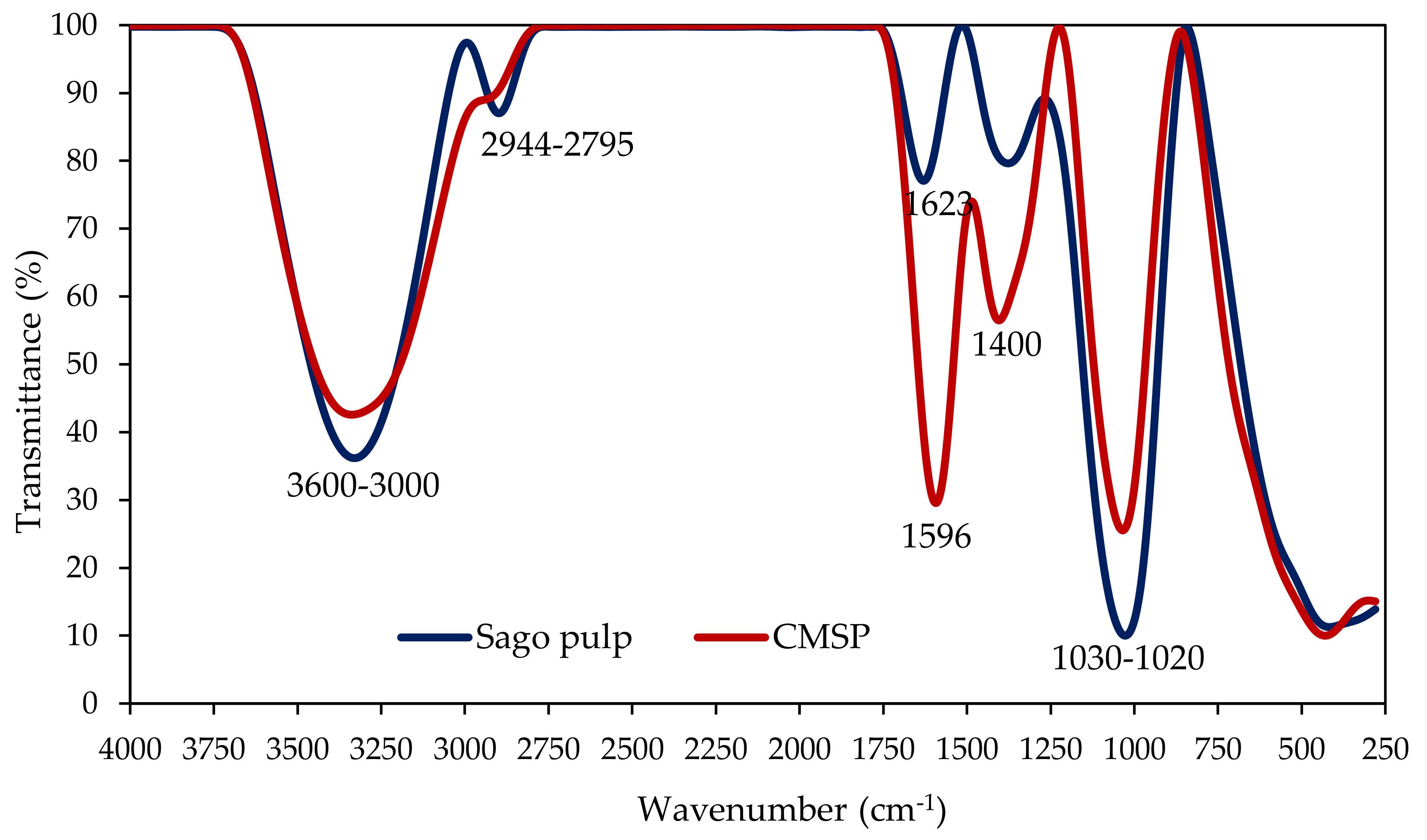
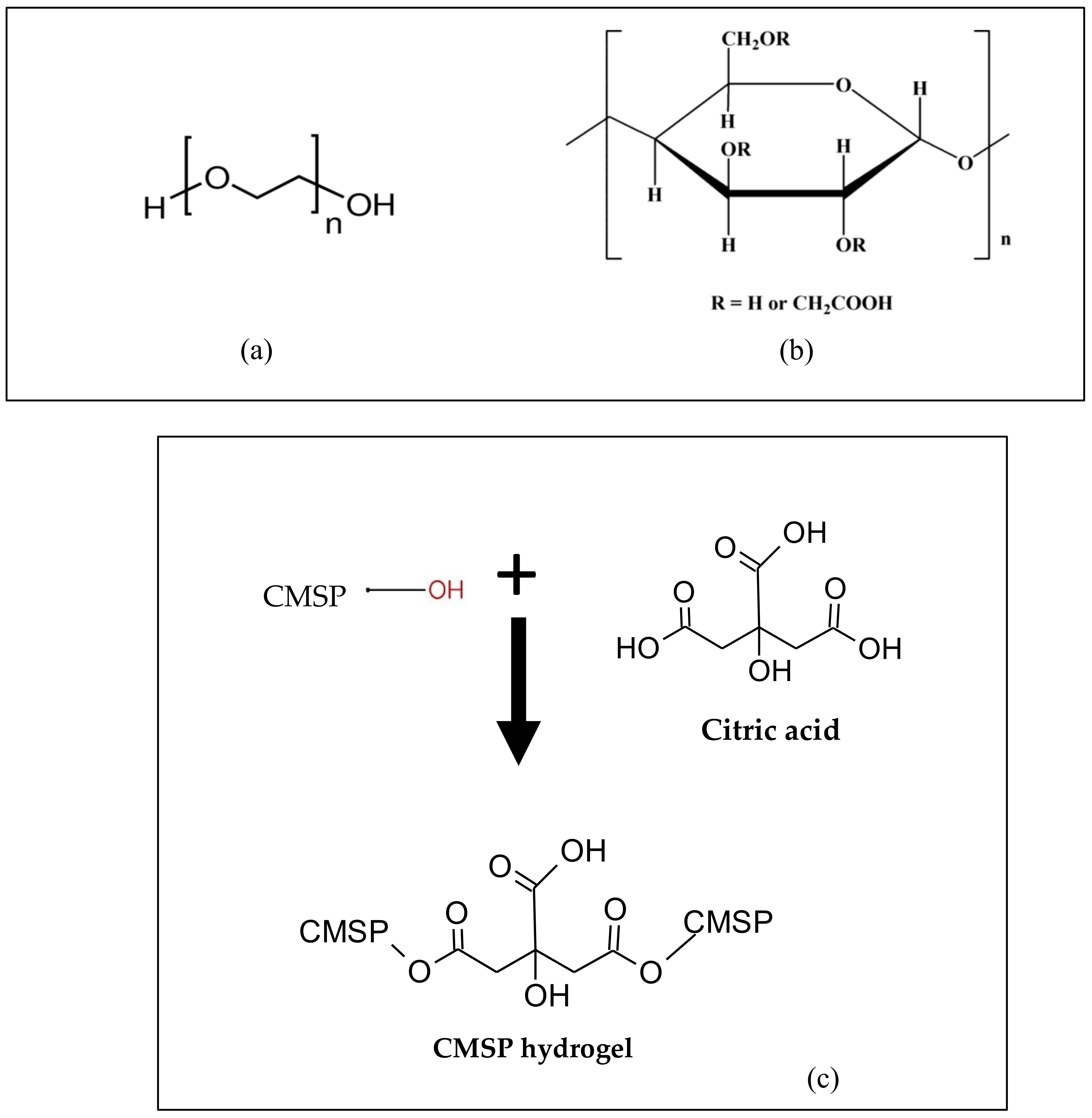
3.1. Fourier Transform Infrared Spectroscopy Studies

Infrared analysis was carried out on the pre-treated sago pulp and CMSP as shown in Figure 1. The pre-treated sago pulp showed a broad O–H stretching vibration band at 3600–3000 cm−1 accompanied with the OH bending vibration of the absorbed water band at 1623 cm−1 [36]. However, in CMSP, the intensity of the O–H stretching vibration was reduced with the OH bending vibration band shifts toward lower wavenumber at 1596 cm−1. The shift of the peak is associated with the COO stretching vibration in CMSP. The features provide evidence on the substitution of OH with the carboxymethyl group in CMSP following the carboxymethylation reaction. The CMSP also demonstrated a strong absorbance band at 1400 cm−1 in comparison to sago pulp which corresponded to the –CH2 scissoring vibration. The sago pulp and CMSP also revealed absorbance bands at 1030–1020 cm−1 which corresponded to the –CH–O–CH2 stretching vibration of the ether group [17]. In sago pulp, the ether group originated from the linkage of 1,4-β-d-glucoside group (>CH–O–CH<) in the cellulose molecule. In CMSP however, the absorbance band of ether also originated from the ether group of the carboxymethylation of sago pulp, in which the two types of ether were overlapped in the CMSP [2,17,18].

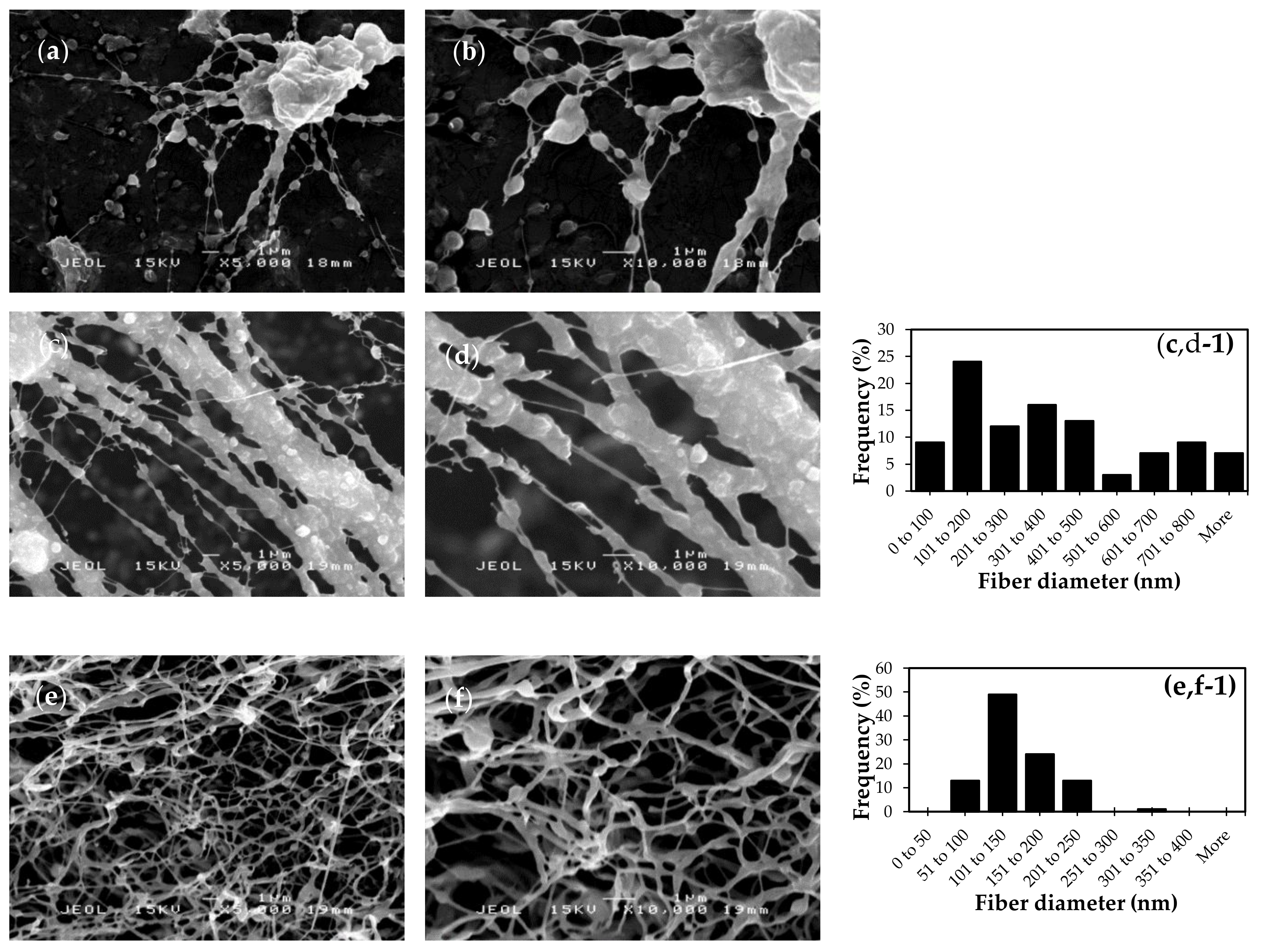
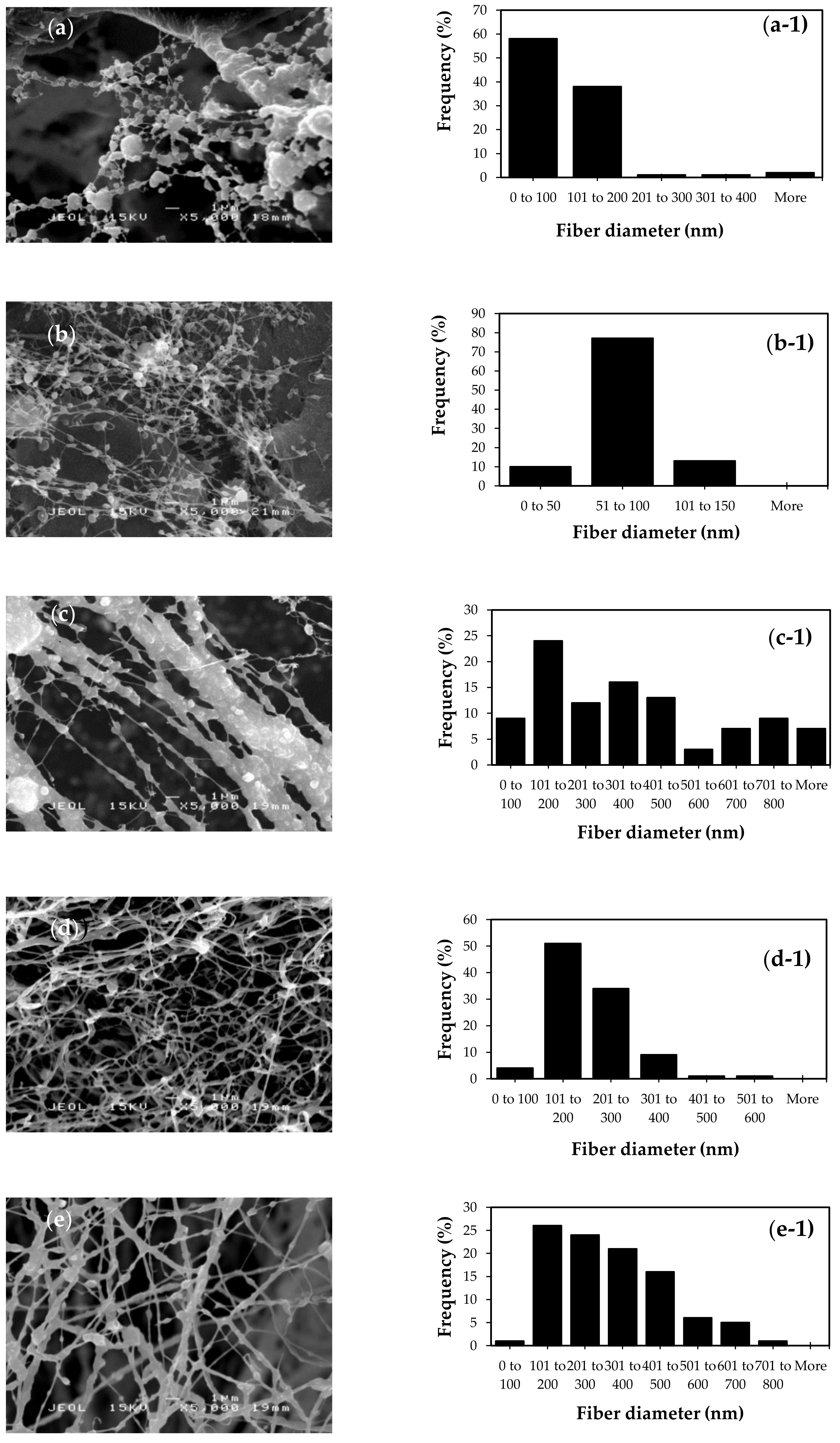
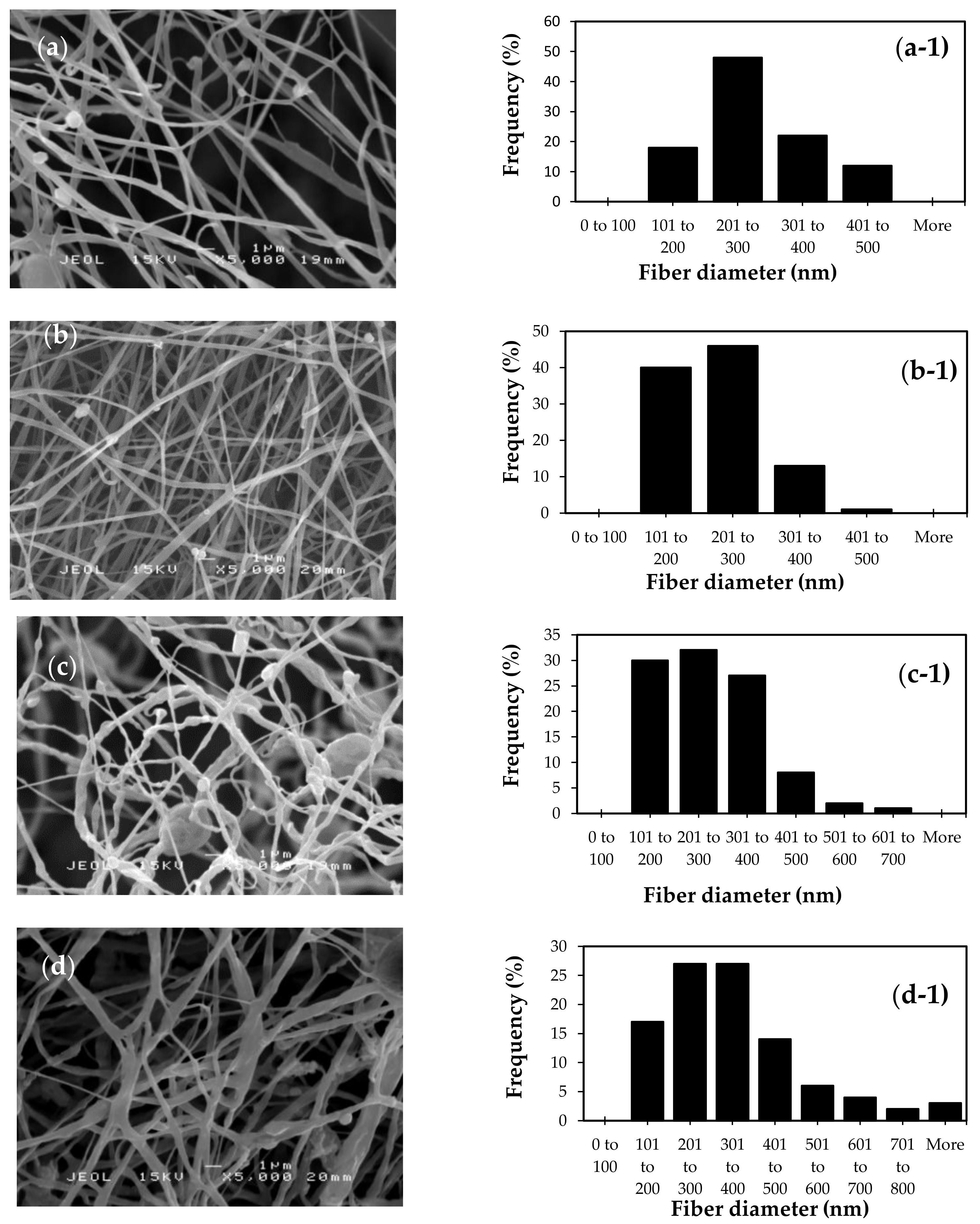
3.2. Optimization of Electrospinning Parameters of CMSP Nanofibers

Optimization of the electrospinning parameters was carried out by varying the weight ratio of CMSP to PEO, the concentration of CMSP/PEO solutions and the CMSP/PEO solution flow rates. The applied voltage was fixed at 20 kV while the tip-to-collector distance was fixed at 15 cm. The electrospinning process was conducted at room temperature while the humidity was kept below 60%.

3.2.1. Effects of Weight Ratio of CMSP to PEO

CMSP is a natural polymer that requires synthetic polymer to assist the electrospinning process. In this study, CMSP was mixed with a biocompatible polymer, PEO, to facilitate the electrospinning process by increasing the elasticity of the CMSP solution [37]. Figure 2 shows the morphology and the average diameter of nanofibers at three different weight ratios of CMSP to PEO. The morphology of the resulting fibers had gradually transformed from microbeads to uniform fiber structure following the variation of CMSP to PEO ratios from 3:1 to 1:3. There was no SEM image to study the morphology of ratio 1CMSP:0PEO because CMSP cannot be electrospun alone. It needs to be blended with electro-spinnable polymer, PEO, to allow CMSP to be electrospun into nanofibers. In the presence of high CMSP content as in 3CMSP:1PEO ratio, the electrospinning process produced a microbead structure with only a few nanofibers as observed from the SEM analysis. At equal ratio of CMSP and PEO, the electrospinning of the mixtures produced nanofibers with wide fiber diameter distribution between 100–1000 nm. However, the presence of microbead structures was still visible from SEM images. At 1CMSP:3PEO ratio, the formation of nanofibers with narrow diameter distribution were observed with average fiber diameter in the range of 51–250 nm. The optimization of the electrospinning process continued using the CMSP:PEO ratios of 1:1 and 1:3, due to significantly less microbead structures produced.

3.2.2. Effects of Concentration of CMSP/PEO Solution

The morphology of nanofibers is significantly affected by the concentration of polymer solution during the electrospinning process [38,39]. In this study, electrospinning was carried out at four different concentrations of CMSP/PEO solutions ~4%, 6%, 8% and 10% (wt/vol%) with the ratio of CMSP to PEO kept at 1:1 and 1:3. SEM images shown in Figure 3 reveal the concentration of solution that significantly affected the formation of nanofibers. At 4% of solution concentration, the presence of microbead structures was observed together with the nanofibers, with average diameter ranging from 100–200 nm. Increasing the concentration had improved the formation of nanofibers with the absence of microbead structures. At 10% concentration, nanofibers obtained at 1:3 and 1:1 ratios showed uniform nanofibers morphology with no visible formation of microbeads. High concentration of polymer in the electrospinning jet significantly enhanced the interaction between polymer chains in solution, which led to a greater resistance of the solution against the pulling force by electrical charges [40]. Nanofibers with narrow mean diameter of 214 ± 62 nm was produced at 10% concentration using 1CMSP:1PEO ratio, which was used for further optimization studies of CMSP/PEO electrospinning.

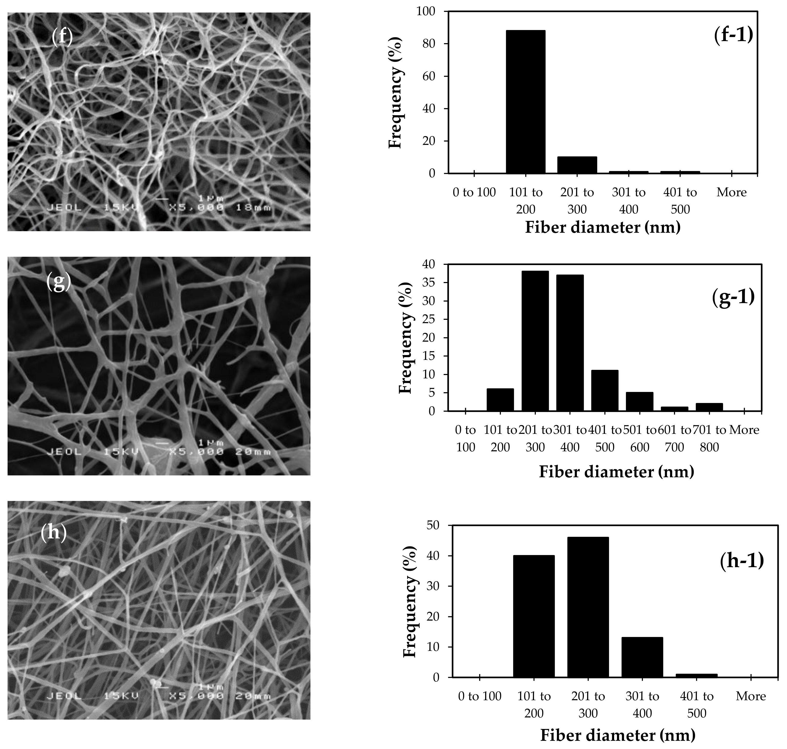
3.2.3. Effects of Flow Rate of Syringe Pump

The influence of flow rate during the electrospinning process was investigated by variation at 0.6, 0.8, 1.0, and 1.2 mL/h and the resulting nanofibers are shown in Figure 4. Nanofibers with a diameter of 280 ± 89 nm were produced at 0.6 mL/h. When the flow rate was increased to 1.2 mL/h, the diameter of nanofibers significantly increased with the maximum size of 355 ± 185 nm obtained at 1.2 mL/h rate. Increasing the flow of solution reduced the time for nanofibers to dry and therefore prompted integration of nanofibers to form a much larger structure [29,41,42]. The nanofibers produced at 0.6 mL/h have relatively uniform structures, although the diameter of resulting nanofibers was significantly larger than nanofibers produced at 0.8 and 1.0 mL/h. Therefore, the flow rate of 0.6 mL/h was considered as the optimum rate for fabrication of CMSP nanofibers. For investigating the degree of swelling, the optimized parameters of 10% solution concentration, 1CMSP:1PEO ratio, 0.6 mL/h flow rate, with the constant 20 kV of applied voltage and 15 cm of tip-to-collector distance, were used to produce hydrogel nanofibers.

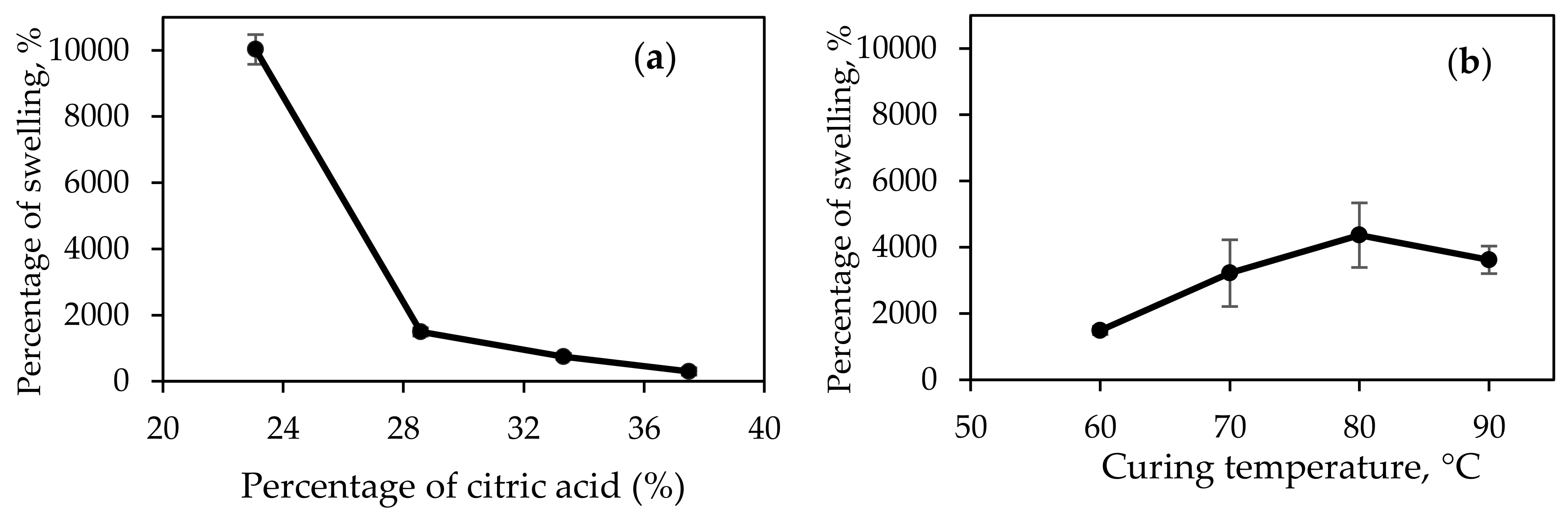
3.3. Swelling Studies of CMSP Hydrogel Nanofibers

Investigation on the swelling percentage of CMSP nanofibers was determined using gravimetric method at a variation of citric acid concentrations and curing temperatures. The duration of curing was kept at 450 min. The percentage of swelling will determine the amount of fluid that can penetrate into the polymeric network, which provides an understanding on the amount of drugs that can retained within the nanofibers structure [43].

3.3.1. Effects of Percentage of Citric Acid

Figure 5a shows the relationship between the percentages of swelling upon increasing the concentrations of citric acid. At 23% of citric acid concentration, the percentage of swelling showed a maximum value of 10,029 ± 449%. However, the percentage of swelling has significantly reduced to 1491 ± 126% at 29% of citric acid concentration. Although the nanofibers showed high percentage of swelling at 23% of citric acid concentration, the hydrogel nanofibers were partially dissolved after 24 h. Citric acid is a cross-linker that bridges two polymeric chains to form a network that will hold water without initiating dissolution. Figure 6 shows the schematic diagram of a cross-linking reaction between hydroxyl groups from CMSP and citric acid molecules. Here, CMSP plays a dominant role in the cross-linking process compared to PEO. PEO has a long linear chain, has only one hydroxyl group at each end of the chain, while CMSP has much more hydroxyl groups. Low concentrations of citric acid produced a small amount of cross-linked networks relative to the amount of hydroxyl groups available for the interaction with water in the hydrogel. In the presence of a large volume of water, the cross-linked network collapsed and consequently increased the dissolution in water. This occurred for hydrogel nanofibers with 23% of citric acid, but not at the higher percentage of citric acid. Moreover, the reason why 23% was chosen as the starting point is because of low percentages lead to total dissolution of hydrogel nanofibers in water. The percentage of swelling for hydrogel nanofibers was decreased when the concentration of citric acid increased to 29%. At high concentrations of citric acid, a high percentage of cross-linked polymeric networks was produced, which significantly improved the ability to retain water molecules in the structure. However, a high percentage of cross-linking also reduced the amount of free hydroxyl groups in the structure, therefore limiting the amount of water that can be accommodated within the network [7,44,45].

3.3.2. Effects of Curing Temperatures

Curing is a process where the nanofibers are treated in an oven at certain periods of time for a cross-linking reaction to occur. The percentage of swelling was further investigated by increasing the curing temperatures of the hydrogel nanofibers at 60 °C, 70 °C, 80 °C and 90 °C. The results in Figure 5b show the highest percentage of swelling at 4366 ± 975% when curing temperatures was at 80 °C. Increasing the temperature from 60 °C to 80 °C gradually improved the percentage of swelling due to the increment of the cross-linked network within the structure. When temperature increased for a constant time duration, the molecules of CMSP, PEO and citric acid moved quicker, while the energy of the molecules increased. This led to a greater frequency of successful collisions between reactant molecules and the greater the rate of a cross-linking reaction. However at 90 °C, the percentage of swelling was slightly decreased, suggesting a large amount of cross-linking between the polymers produced and caused a rigid cross-linked network. Optimization of the amount of citric acid and the curing temperature on the degree of swelling provides an insight into the ability of hydrogel to adsorb and hold methylene blue within the polymeric network. The optimum CMSP/PEO hydrogel nanofibers (10% concentration, 1:1 ratio, 29% of citric acid, 80 °C of curing temperature and 450 min of curing time) was prepared to proceed with the drug release study.
In this swelling study, a traditional and widely used method of measuring the percentage of swelling is based on the weight of the hydrogel. Inaccuracy of measuring the percentage of swelling may occur due to difficulty in handling swelling hydrogel nanofibers as they have a delicate structure. Structural destruction of hydrogel might occur during weight measurement because swelling of hydrogel nanofibers having low mechanical properties. Extra precaution was taken in this study to ensure accurate result. Recently, a new and more efficient method had been found by Tavakoli et al. (2019) to overcome all the limitations and errors in traditional methods which is known as the fluorescence intensity method (FL). This new method can be employed for obtaining accurate measurements of percentage of swelling hydrogels, especially delicate nanofibers [46].

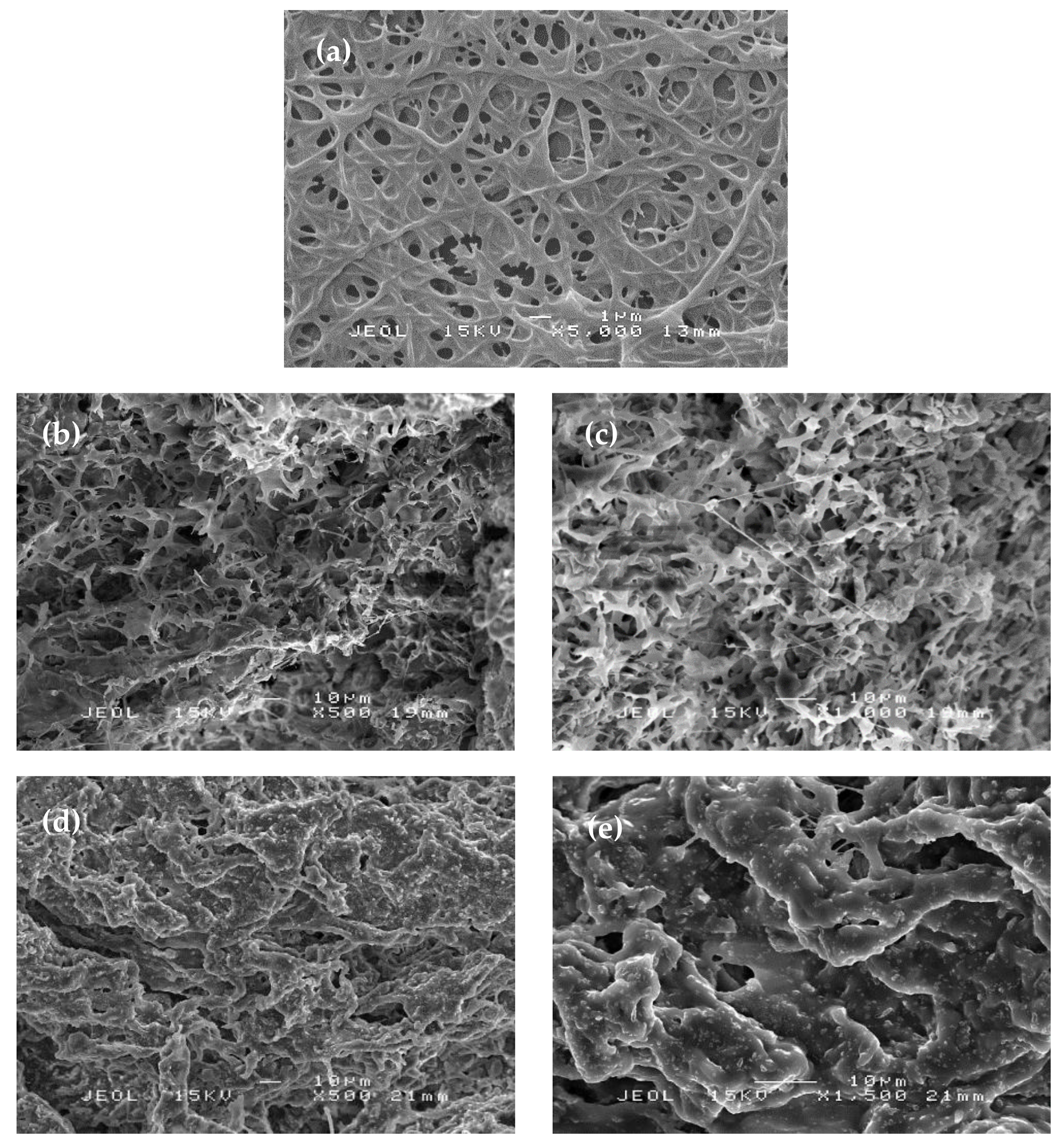
3.4. Morphology Studies

SEM images of the cross-linked CMSP hydrogel nanofibers following immersion in water in swelling studies and adsorption with MB are shown in Figure 7. The morphology of CMSP nanofibers hydrogel was significantly different compared to CMSP nanofibers as shown in Figure 4. The SEM image in Figure 7a shows the CMSP hydrogel nanofibers that were still in nanofibrous form after the cross-linking reaction. This proved that a cross-linking reaction does not affect the morphology of the CMSP nanofibers. The SEM analysis in Figure 7b,c demonstrates swollen nanofibers with the appearance of porous structures. The expansion of the fiber diameter and the formation of porous structures proved that the absorption of water into the hydrogel network produced a high percentage of swelling of the CMSP nanofibers. The nanofibers were cross-linked to form a polymeric network with voids to hold water. The SEM images in Figure 7d,e illustrate the morphology of hydrogel nanofibers following immersion with MB was different than immersion with water, whereby the nanofibers showed bigger enlargement with less pores and void spaces within the hydrogel network.

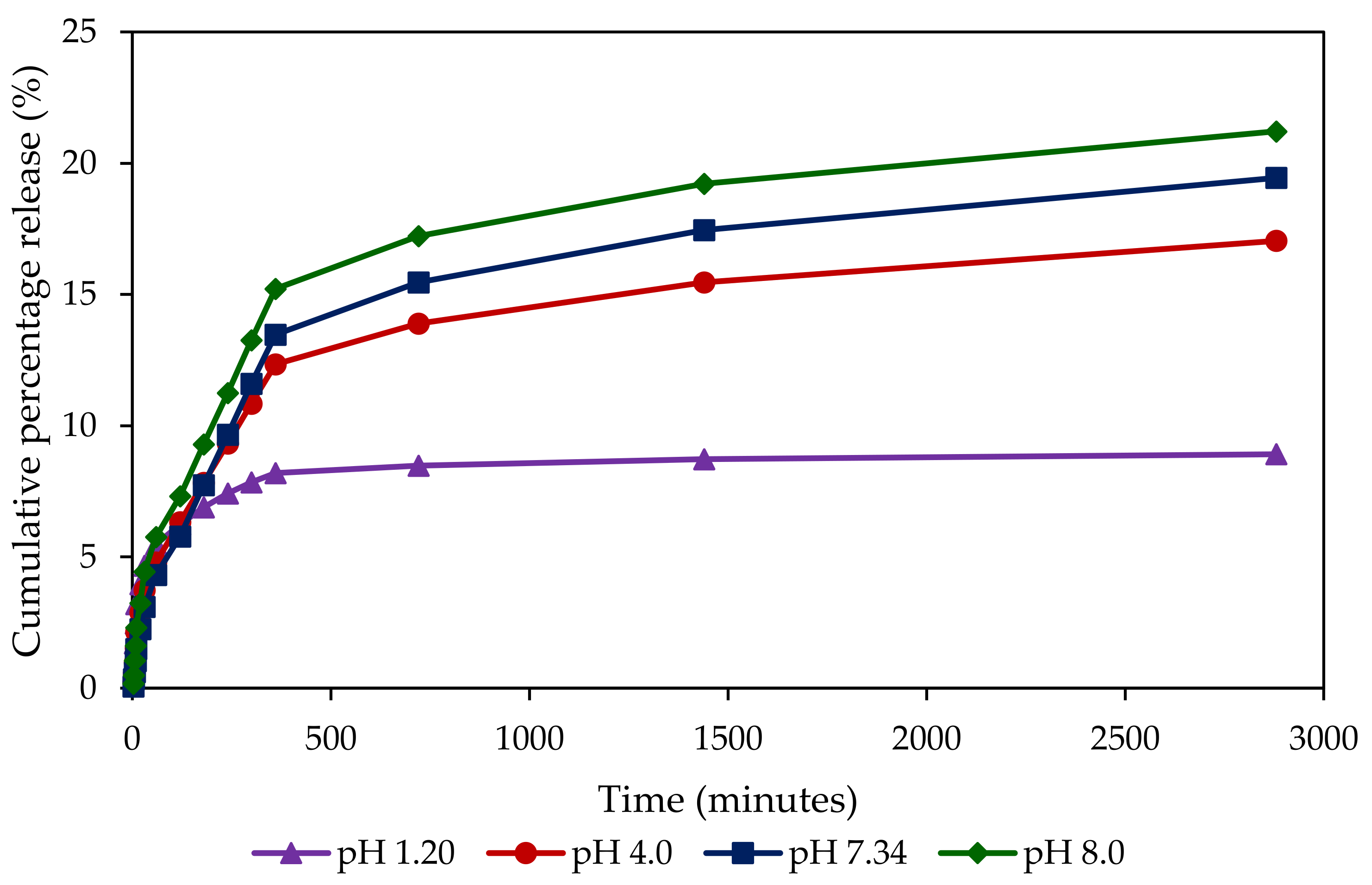
3.5. Drug Release Studies

The potential of CMSP hydrogel nanofibers to be used as a drug carrier was investigated on the ability to release the adsorbed MB at various pHs. Investigations on pH variation is important to simulate the physiological environments along the human gastrointestinal (GI) tract starting with the saliva at pH 5–6, stomach at pH 1–3, small intestine at pH 6.6–7.5 and colon at pH 6.4–7.0 [10,47,48]. When necessary, the drug release ability at pH 7.15–8.9 is crucial to heal chronic wounds [10,49]. However, the delicate structure of hydrogel nanofibers may be unsuitable for oral administration. Nevertheless, it can be further applied as wound dressings in wound treatments. Drug release from polymers occurs when a liquid medium penetrates the polymeric network leading to the release of the retained drug by diffusion. Figure 8 shows the MB release profiles from hydrogel nanofibers at different pH of buffer solutions. In general, the CMSP shows a high degree of MB releases at high pH, with the highest cumulative percentage after 2880 min obtained at pH 8.0 (21.21%). Within 30 min into the investigation, the acceleration of MB diffusion was observed in all pH media with similar cumulative percentage releases of ~5% suggesting the diffusion of MB from CMSP hydrogel nanofibers trapped on the surface of the nanofibers. The initial diffusion of the surface trapped MB also occurred at a similar rate which suggests that the process was not influenced by the pH of the solution. Monitoring the concentration of MB after 6 h showed a rapid diffusion of MB when the pH of buffer solution was 7.34, and the rates were slowly reduced as the pH decreases to 1.2. At pH 1.2, the degree of drug release achieved a steady state at 6h, with only 9% of MB detected after 2880 min.
The diffusion of MB from the hydrogel network was influenced by the pH of the surrounding medium as MB is a cationic type drug. At low pH, where high level of proton concentration is available, an equilibrium state between MB and protonated water occurred, which reduced the diffusion of MB. Increasing the pH of the buffer solution created osmotic pressure in the surroundings that subsequently increased the diffusion of MB from the hydrogel network through the channels and pores of nanofibers. A low cumulative percentage release of MB in all pHs of the buffer solutions that are less than 22% indicates the potential use of hydrogel derived from sago pulp waste to prolong the MB retaining time and reduce the dosing frequency of MB. This study suggests that the controlled released of MB from hydrogels is also associated with the presence of cross-linkages between the nanofibers polymers, thus restricting the diffusion rate of MB into the surrounding medium.

4. Conclusions

This study has investigated the modification of cellulose obtained from sago waste in forming hydrogel nanofibers as a potential drug carrier in wound treatments. The CMSP nanofibers were produced using the electrospinning method with the addition of PEO, which increased the structure and morphology of the nanofibers. The concentration of CMSP/PEO solution, the ratio between CMSP and PEO, and the flow rate of CMSP/PEO during electrospinning, significantly influenced the morphology and size of the nanofibers. An investigation on the percentage of swelling showed that the presence of citric acid and the variation of curing temperatures increased the number of cross-linked networks between the nanofibers to form strong polymeric structures responsible for the swelling process. Drug release studies using MB as a probe molecule showed that hydrogel nanofibers obtained from CMSP has a loading efficiency of 89.20 ± 0.42%. Drug release profiles of MB-loaded hydrogel nanofibers were significantly influenced by the pH of buffer solutions and revealed slow release in all pHs, which perhaps demonstrate the potential use of CMSP hydrogel nanofibers as an in vivo or in vitro drug carrier. This preliminary work has illustrated the potential of CMSP nanofibers as a drug carrier that is not only limited to the incorporation of MB, but also applicable for any of hydrophilic pharmaceutical drugs. Due to the delicate nature of hydrogel nanofibers structure, CMSP/PEO hydrogel nanofibers are more suitable for applications, like wound dressing rather than oral administration.

Author Contributions

The work presented in this paper was a collaboration of all authors. The work contribution among the authors as follow: conceptualization, N.A.R.; methodology, N.M.K. and N.H.R.; software, N.M.K.; validation, N.A.R. and N.M.K., and N.A.R.; formal analysis, N.M.K.; investigation, N.M.K.; resources, N.M.K.; data curation, N.M.K.; writing—original draft preparation, N.M.K.; writing—review and editing, H.B. and H.M.; visualization, N.M.K.; supervision, N.A.R.; project administration, N.A.R.; funding acquisition, N.A.R.

Funding

This research was funded by Universiti Putra Malaysia, grant number GP-IPS/2016/9594900 and Graduate Research Fund (GRF) for Nafeesa Mohd Kanafi scholarship. Check carefully that the details given are accurate and use the standard spelling of funding agency names at https://0-search-crossref-org.brum.beds.ac.uk/funding, any errors may affect your future funding.

Acknowledgments

Authors would like to acknowledge Universiti Putra Malaysia for financial supports through Research University Grant (Grant code: GP-IPS/2016/9594900). Authors would also acknowledge Graduate Research Fund (GRF) for Nafeesa Mohd Kanafi from Universiti Putra Malaysia.

Conflicts of Interest

The authors declare no conflicts of interest.

References

  1. Bujang, K.B.; Hassan, M.A. Recovery of Glucose from Residual Starch of Sago Hampas for Bioethanol Production. Biomed. Res. Int. 2013, 2013, 1–8. [Google Scholar]
  2. Pushpamalar, V.; Langford, S.J.; Ahmad, M.; Lim, Y.Y. Optimization of reaction conditions for preparing carboxymethyl cellulose from sago waste. Carbohydr. Polym. 2006, 64, 312–318. [Google Scholar] [CrossRef]
  3. Deparment of Agriculture Sarawak. Available online: https://www.doa.sarawak.gov.my (accessed on 30 July 2018).
  4. Veeramachineni, A.K.; Sathasivam, T.; Muniyandy, S. Optimizing Extraction of Cellulose and Synthesizing Pharmaceutical Grade Carboxymethyl Sago Cellulose from Malaysian Sago Pulp. Appl. Sci. 2016, 6, 170. [Google Scholar] [CrossRef]
  5. Frenot, A.; Henriksson, M.W.; Walkenstro, P. Electrospinning of Cellulose-Based Nanofibers. J. Appl. Polym. Sci. 2007, 103, 1473–1482. [Google Scholar] [CrossRef]
  6. Kanafi, N.M.; Rahman, N.A.; Rosdi, N.H. Citric acid cross-linking of highly porous carboxymethyl cellulose/poly (ethylene oxide) composite hydrogel films for controlled release applications. Mater Today Proc. 2019, 7, 721–731. [Google Scholar] [CrossRef]
  7. Shen, X.; Shamshina, J.L.; Berton, P.; Rogers, R.D. Hydrogels based on cellulose and chitin: Fabrication, properties and applications. Green Chem. 2015, 18, 53–75. [Google Scholar] [CrossRef]
  8. Tan, H.L.; Wong, Y.Y.; Muniyandy, S.; Hashim, K. Carboxymethyl sago pulp/carboxymethyl sago starch hydrogel: Effect of polymer mixing ratio and study of controlled drug release. J. Appl. Polym. Sci. 2016, 43652, 1–13. [Google Scholar] [CrossRef]
  9. Barbucci, R.; Magnani, A.; Consumi, M. Swelling Behavior of Carboxymethylcellulose Hydrogels in Relation to Cross-Linking pH and Charge Density. Macromolecules 2000, 33, 7475–7480. [Google Scholar] [CrossRef]
  10. Rizwan, M.; Yahya, R.; Hassan, A.; Yar, M.; Azzahari, A.; Selvanathan, V.; Sonsudin, F.; Abouloula, C. pH sensitive hydrogels in drug delivery: Brief history, properties, swelling, and release mechanism, material selection and applications. Polymers 2017, 9, 137. [Google Scholar] [CrossRef]
  11. Abrigo, M.; Mcarthur, S.L.; Kingshott, P. Electrospun Nanofibers as Dressings for Chronic Wound Care: Advances, Challenges, and Future Prospects. Macromol. Biosci. 2014, 14, 772–792. [Google Scholar] [CrossRef]
  12. Tavakoli, J.; Mirzaei, S.; Tang, Y. Cost-effective double-layer hydrogel composites for wound dressing applications. Polymers 2018, 10, 305. [Google Scholar] [CrossRef] [PubMed]
  13. Raucci, M.G.; Demitri, C.; Giugliano, D.; Benedictis, V.; de Sannino, A.; Ambrosio, L. Effect of citric acid crosslinking cellulose-based hydrogels on osteogenic differentiation. J. Biomed. Mater. Res. 2014, 103A, 2045–2056. [Google Scholar] [CrossRef] [PubMed]
  14. Arslan, N. Production of carboxymethyl cellulose from sugar beet pulp cellulose and rheological behaviour of carboxymethyl cellulose. Carbohydr. Polym. 2003, 54, 73–82. [Google Scholar]
  15. Biswas, A.; Kim, S.; Selling, G.W.; Cheng, H.N. Conversion of agricultural residues to carboxymethylcellulose and carboxymethylcellulose acetate. Ind. Crop. Prod. 2014, 60, 259–265. [Google Scholar] [CrossRef]
  16. Bono, A.; Ying, P.H.; Yan, F.Y.; Muei, C.L.; Sarbatly, R.; Krishnaiah, D. Synthesis and Characterization of Carboxymethyl Cellulose from Palm Kernel Cake. Adv. Nat. Appl. Sci. 2009, 3, 5–11. [Google Scholar]
  17. Rachtanapun, P.; Luangkamin, S.; Tanprasert, K.; Suriyatem, R. Carboxymethyl cellulose fi lm from durian rind. YFSTL 2012, 48, 52–58. [Google Scholar]
  18. Pushpamalar, V.; Langford, S.J.; Ahmad, M.; Hashim, K. Preparation of Carboxymethyl Sago Pulp Hydrogel from Sago Waste by Electron Beam Irradiation and Swelling Behavior in Water and Various pH Media. J. Appl. Polym. 2013, 128, 451–459. [Google Scholar] [CrossRef]
  19. Lyn, Y.; Muniyandy, S.; Kamaruddin, H.; Mansor, A.; Janarthanan, P. Radiation cross-linked carboxymethyl sago pulp hydrogels loaded with ciprofloxacin: Influence of irradiation on gel fraction, entrapped drug and in vitro release. Radiat. Phys. Chem. 2015, 106, 213–222. [Google Scholar]
  20. Thenapakiam, S.; Kumar, D.G.; Pushpamalar, J.; Saravanan, M. Aluminium and radiation cross-linked carboxymethyl sago pulp beads for colon targeted delivery. Carbohydr. Polym. 2013, 94, 356–363. [Google Scholar] [CrossRef]
  21. Rathinamoorthy, R.; Technology, F.; College, P.S.G. Nanofiber for drug delivery system. Pak Text J. 2012, 61, 45–48. [Google Scholar]
  22. Haider, A.; Haider, S.; Kang, I. A comprehensive review summarizing the effect of electrospinning parameters and potential applications of nanofibers in biomedical and biotechnology. Arab. J. Chem. 2015, 11, 015. [Google Scholar] [CrossRef]
  23. Teck, C. Progress in Polymer Science Nanofiber technology: Current status and emerging developments. Prog. Polym. Sci. 2017, 70, 1–17. [Google Scholar]
  24. Samadian, H.; Salehi, M.; Farzamfar, S.; Vaez, A.; Ehterami, A.; Sahrapeyma, H.; Goodarzi, A.; Ghorbani, S. In vitro and in vivo evaluation of electrospun cellulose acetate/gelatin/hydroxyapatite nanocomposite mats for wound dressing applications. Artif. Cells Nanomed. Biotechnol. 2018, 46, 964–974. [Google Scholar] [CrossRef] [PubMed]
  25. Basu, P.; Repanas, A.; Glasmacher, B.; Narendrakumar, U.; Manjubala, I. PEO-CMC blend nanofibers fabrication by electrospinning for soft tissue engineering applications. Mater. Lett. 2017, 195, 10–13. [Google Scholar] [CrossRef]
  26. Schirmer, R.H.; Coulibaly, B.; Stich, A.; Scheiwein, M.; Merkle, H.; Eubel, J.; Becker, H.; Muller, O.; Zich, T.; Schiek, W. Methylene blue as an antimalarial agent. Redox Rep. 2003, 8, 272–275. [Google Scholar] [CrossRef] [PubMed] [Green Version]
  27. Oz, M.; Lorke, D.E.; Petroianu, G.A. Methylene blue and Alzheimer’s disease. Biochem. Pharmacol. 2009, 78, 927–932. [Google Scholar] [CrossRef] [PubMed]
  28. Wendel, W.B. The control of methemoglobinemia with methylene blue. J. Clin. Investig. 1939, 18, 179–185. [Google Scholar] [CrossRef] [PubMed]
  29. Pillay, V.; Dott, C.; Choonara, Y.E.; Tyagi, C.; Tomar, L.; Kumar, P.; Ndesendo, V. MA Review of the Effect of Processing Variables on the Fabrication of Electrospun Nanofibers for Drug Delivery Applications. J. Nanomat. 2013, 2013, 1–22. [Google Scholar] [CrossRef]
  30. Dahlan, N.A.; Ng, S.L.; Pushpamalar, J. Adsorption of methylene blue onto powdered activated carbon immobilized in a carboxymethyl sago pulp hydrogel. J. Appl. Polym. Sci. 2017, 134. [Google Scholar] [CrossRef]
  31. Giani, G.; Fredi, S.; Barbucci, R. Hybrid magnetic hydrogel: A potential system for controlled drug delivery by means of alternating magnetic fields. Polymers 2012, 4, 1157–1169. [Google Scholar] [CrossRef]
  32. Foroutan, H.; Khodabakhsh, M.; Rabbani, M. Investigation of synthesis of PVP hydrogel by irradiation. Iran J. Radiat. Res. 2007, 5, 131–136. [Google Scholar]
  33. Huang, W.F.; Tsui, G.C.P.; Tang, C.Y.; Yang, M. Optimization Strategy for Encapsulation Efficiency and Size of Drug Loaded Silica Xerogel/Polymer Core-Shell Composite Nanoparticles Prepared by Gelation-Emulsion Method. Polym. Eng. Sci. 2017, 58, 742–751. [Google Scholar] [CrossRef]
  34. Shi, Y.; Wan, A.; Shi, Y.; Zhang, Y.; Chen, Y. Experimental and Mathematical Studies on the Drug Release Properties of Aspirin Loaded Chitosan Nanoparticles. BioMed. Res. Int. 2014, 2014. [Google Scholar] [CrossRef] [PubMed]
  35. Chandrasekaran, A.R.; Jia, C.Y.; Theng, C.S.; Muniandy, T.; Muralidharan, S.; Arumugam, S. Invitro studies and evaluation of metformin marketed tablets-Malaysia. J. Appl. Pharm. Sci. 2011, 1, 214–217. [Google Scholar]
  36. Bolio-López, G.I.; Ross-Alcudia, R.E.; Veleva, L.; Azamar, J.A.; Barrios, G.C.M.; Hernández-Villegas, M.M.; Córdova, S.S. Extraction and Characterization of Cellulose from Agroindustrial Waste of Pineapple (Ananas comosus L. Merrill) Crowns. Chem. Sci. Rev. Lett. 2016, 5, 198–204. [Google Scholar]
  37. Fernandes, J.G.; Correia, D.M.; Botelho, G.; Padrão, J.; Dourado, F. PHB-PEO electrospun fiber membranes containing chlorhexidine for drug delivery applications. Polym. Test. 2014, 34, 64–71. [Google Scholar] [CrossRef] [Green Version]
  38. Greiner, A.; Wendorff, JH. Electrospinning: A Fascinating Method for the Preparation of Ultrathin Fibers. Angew. Chem. Int. Ed. 2007, 46, 5670–5703. [Google Scholar] [CrossRef] [PubMed]
  39. Rogina, A. Applied Surface Science Electrospinning process: Versatile preparation method for biodegradable and natural polymers and biocomposite systems applied in tissue engineering and drug delivery. Appl. Surf. Sci. 2014, 296, 221–230. [Google Scholar] [CrossRef]
  40. Sadat, A.; Hamid, M.; Hajiesmaeilbaigi, F. Effect of electrospinning parameters on morphological properties of PVDF nanofibrous scaffolds. Prog. Biomater. 2017, 6, 113–123. [Google Scholar]
  41. Megelski, S.; Stephens, J.S.; Chase, D.B.; Rabolt, J.F. Micro and Nanostructured Surface Morphology on Electrospun Polymer Fibers. Macromolecules 2002, 35, 8456–8466. [Google Scholar] [CrossRef]
  42. Rodoplu, D.; Mutlu, M. Effects of Electrospinning Setup and Process Parameters on Nanofiber Morphology Intended for the Modification of Quartz Crystal Microbalance Surfaces. J. Eng. Fibers Fabr. 2012, 7, 118–123. [Google Scholar] [CrossRef]
  43. Kumar, S.U.; Matai, I.; Dubey, P.; Bhushan, B.; Sachdev, A. Supporting information Differentially cross-linkable core-shell nanofibers for tunable delivery of anticancer drugs: Synthesis, characterization and its anticancer efficacy. Electron. Suppl. Mat. 2014, 4, 38263–38272. [Google Scholar]
  44. Khan, S.; Ranjha, N.M. Effect of degree of cross-linking on swelling and on drug release of low viscous chitosan/poly(vinyl alcohol) hydrogels. Polym. Bull. 2014, 71, 2133–2158. [Google Scholar] [CrossRef]
  45. Reddy, N. Citric acid cross-linking of starch films. Food Chem. 2010, 118, 702–711. [Google Scholar] [CrossRef] [Green Version]
  46. Tavakoli, J.; Zhang, H.P.; Tang, B.Z.; Tang, Y. Aggregation-induced emission lights up the swelling process: A new technique for swelling characterisation of hydrogels. Mater. Chem. Front. 2019, 3, 664–667. [Google Scholar] [CrossRef]
  47. Bhattarai, N.; Gunn, J.; Zhang, M. Chitosan-based hydrogels for controlled, localized drug delivery. Adv. Drug Deliv. Rev. 2010, 62, 83–99. [Google Scholar] [CrossRef]
  48. George, M.; Abraham, T.E. pH sensitive alginate-guar gum hydrogel for the controlled delivery protein drugs. Int. J. Pharm. 2007, 335, 123–129. [Google Scholar] [CrossRef]
  49. Percival, S.L.; Mccarty, S.; Hunt, J.A.; Woods, E.J. The effects of pH on wound healing, biofilms and antimicrobial efficacy. Wound Rep. Reg. 2014, 22, 174–186. [Google Scholar] [CrossRef]
Figure 1. Fourier transform infrared (FTIR) spectra pattern of pre-treated sago pulp and carboxymethyl sago pulp (CMSP).
Fibers 07 00056 g001
Figure 2. SEM images (af) and the corresponding fiber diameter distribution ((c,d-1)–(e,f-1)) of CMSP nanofibers at variation of CMSP to poly(ethylene oxide) (PEO) weight ratios (a)–(b) 3:1, (c)–(d) 1:1 and (e)–(f) 1:3 at fixed 6% solution concentration, 20 kV applied voltage, 15 cm of tip-to-collector distance and 0.8 mL/h of flow rate.
Fibers 07 00056 g002
Figure 3. SEM images (ah) and the corresponding fiber diameter distribution ((a-1)–(h-1)) of CMSP/PEO nanofibers at different concentration of CMSP to PEO solution and ratio of CMSP to PEO (a) 4% (ratio 1:1), (b) 4% (ratio 1:3), (c) 6% (ratio 1:1), (d) 6% (ratio 1:3), (e) 8% (ratio 1:1), (f) 8% (ratio 1:3), (g) 10% (ratio 1:1) and (h) 10% (ratio 1:3). Electrospinning parameters were kept constant at 20 kV for applied voltage, 15 cm of tip-to-collector distance and 0.8 mL/h for flow rate.
Fibers 07 00056 g003aFibers 07 00056 g003b
Figure 4. SEM images (ad) and the corresponding fiber diameter distribution ((a-1)–(d-1)) of CMSP nanofibers produced at flow rate of (a) 0.6 mL/h, (b) 0.8 mL/h, (c) 1.0 mL/h and (d) 1.2 mL/h at fixed 10% concentration, 1:1 ratio, 20 kV of applied voltage and 15 cm tip-to-collector distance.
Fibers 07 00056 g004
Figure 5. Plot of percentage of swelling at (a) different percentage of citric acid (23%, 29%, 33% and 38%) at fixed 60 °C and 450 min of curing; and (b) different curing temperature (60 °C, 70 °C, 80 °C and 90 °C) but at fixed 29% citric acid, 450 min of curing.
Fibers 07 00056 g005
Figure 6. (a) PEO structure (b) CMSP structure (c) Proposed mechanism of cross-linking reaction between cellulose (CMSP) and citric acid.
Fibers 07 00056 g006
Figure 7. SEM images of (a) cross-linked CMSP hydrogel nanofibers; (b,c) swollen CMSP hydrogel nanofibers; and (d,e) methylene blue (MB)-loaded CMSP hydrogel nanofibers.
Fibers 07 00056 g007
Figure 8. Effects of pH value on the release of MB from CMSP hydrogel nanofibers.
Fibers 07 00056 g008

