Article

Performance of Concrete Confined with a Jute–Polyester Hybrid Fiber Reinforced Polymer Composite: A Novel Strengthening Technique

1
Faculty of Engineering, Kasetsart University, Bangkok 10900, Thailand
2
Department of Chemical Engineering, Faculty of Engineering, Kasetsart University, Bangkok 10900, Thailand
3
Construction and Maintenance Technology Research Center (CONTEC), School of Civil Engineering and Technology, Sirindhorn International Institute of Technology, Thammasat University, Bangkok 10110, Thailand
4
School of Engineering, University of Phayao, Chang Wat Phayao 56000, Thailand
*
Authors to whom correspondence should be addressed.
Submission received: 19 July 2019 / Revised: 2 August 2019 / Accepted: 5 August 2019 / Published: 8 August 2019

Abstract

:
The strengthening and rehabilitation of concrete members is an important issue which arises worldwide. Carbon, aramid and glass fiber reinforced polymer (FRP) composites are mainly used for strengthening and rehabilitation. However, its use is limited on a small scale because of its high price, lack of availability and environmental impacts. The solution of this issue gives rise to the use of locally available natural fibers and low-cost synthetic fibers. This paper presents the experimental and analytical results of circular and square concrete columns confined with jute–polyester hybrid FRP composites. The main objective of this study is to evaluate the viability and performance of concrete confined with the hybridization of jute and polyester (FRP) composite sheets to utilize its superior properties. A novel hybrid technique has been applied for the wrapping of fiber sheets. The fiber sheets were applied in such a way that a uniform bond between the inner and outer layer was achieved. A total of 32 plain, standard size circular and square concrete specimens, externally wrapped with a jute–polyester FRP (JPFRP) composite, were tested under monotonic axial compressive loads. The result shows that JPFRP confinement increased the strength, strain and ductility index ranged between 1.24 and 2.61, 1.38 and 8.97, and 4.94 and 26.5 times the un-jacketed specimen, respectively. Furthermore, the wrapping has a significant effect on the low-strength specimens, having a circular cross-section. For high strength specimens, the post-peak stress-strain behavior was dominated by the outer polyester jacket because of its large rupture strain. Additionally, the test results were used to evaluate the existing strength-strain models derived for conventional FRPs. The models predicted values either underestimating or overestimating the compressive strength and strain of JPFRP-confined specimens. However, the strength models performed better than the strain models. The JPFRP wrapping significantly enhanced the strength, fracture energy, ductility index, and post-peak response. Therefore, JPFRP confinement can be used for a small-scale application, where little strength and high ductility is demanded. Moreover, it can be used to prevent the peeling of the concrete cover and moisture penetration into the concrete.

1. Introduction

Reinforced concrete structures may experience structural deficiencies and damages from the start of the construction stage until the end of its service life. During the construction stage, the structure may experience structural defects because of the structural design errors, low-quality concrete production, and bad workmanship in execution processes. Moreover, in its service life, damages can be attributed to various reasons such as cracking and peeling of the concrete cover, occurrence of an earthquake, increase in live loads, or an accident, for example, fire and explosions [1]. In addition, corrosion of steel reinforcement and carbonation of concrete are also some of the problems which arise worldwide depending on the exposure of the structure to its external environment [2]. Hence, to maintain the structural integrity and safety requirements, the damaged and structurally deficient buildings need to be strengthened or rebuilt. However, demolition and rebuilding of a structure are not considered an economically viable solution because of its high cost, environmental impacts, and low time efficiency [3]. Therefore, structural strengthening and repairing of a deficient reinforced concrete (RC) structure is a preferable option in terms of economic and environmental aspects. In the past, several techniques were employed for the upgradation of reinforced concrete structures to sustain its structural integrity and to ensure the serviceability. Reinforced concrete jacketing and steel jacketing have been used to repair and upgrade the structural properties of the reinforced concrete structures. Reinforced concrete jacketing can enhance the compressive strength and ductility of the structure. However, this method is labor-intensive, time-consuming, and sometimes in situ implementation is difficult [4]. Besides, corrosion of internal steel may occur due to a prolonged exposure to moisture, and penetration of chlorides can also result in concrete cracking and spalling. Hence, such methods are considered appropriate in an environment where the corrosion intensity is under acceptable limits. Therefore, an advanced, easy to install, and durable strengthening system is needed to replace out of date methods.
To replace the old strengthening methods, extensive research was carried out for finding an alternative material for strengthening purpose. As a result, fiber reinforced polymer (FRP) composites have emerged as a potentially promising material for rehabilitation and strengthening of deficient reinforced concrete structural elements, particularly RC columns, which essentially supports the entire bridge structures and buildings. The most attractive features of FRPs are the ease of installation, non-corrodibility, high tensile strength, high versatility, and high-strength-to-weight ratio. These salient properties of FRPs make them one of the most prevalent materials for structural rehabilitation. Many experimental studies reported that external wrapping by FRP composite could remarkably increase the load-carrying ability of circular, square, and rectangular concrete columns [5,6,7]. Different types of FRPs have been used for the lateral confinement of concrete columns, which includes carbon [8,9,10,11,12,13,14], glass [7,15,16,17,18], aramid [6,19,20,21], polyethylene napthalate (PEN) [22,23], polyethylene terephthalate (PET) [22,23,24,25,26], and basalt [27,28,29]. These FRP composites are effectively used in enhancing the load-bearing capacity and energy absorption of masonry and reinforced concrete infrastructures. In Japan, carbon fiber has been successfully utilized in strengthening and rehabilitation of columns, freeway piers, and chimneys [30]. Jing et al. [31] summarized that carbon and glass FRP jacketing is very effective in improving the ultimate compressive strength and axial strain of concrete columns with circular cross-sections. Due to its linear elastic nature, the lateral confinement system by FRPs has been proved very successful by enhancing the compressive strength and axial strain of concrete members without substantial increase in its cross-section and weight. Despite its advantages, currently, the wider application of carbon/Glass FRP (C/GFRP) is restricted by their high cost, lack of enough performance-based long-term data availability, fire risk, and environmental impacts [32,33].
Therefore, nowadays, efforts have been made to replace the conventional composite materials, i.e., C/GFRP, with alternate materials for civil infrastructure applications, to gain economic and environmental benefits. Studies were conducted on the use of economical and environmentally friendly fibers including hemp [34,35], sisal [36,37,38], jute [36,37,39], coir, and flax [33,40]. Previous studies exemplify that natural fibers have high potential in the reinforcement of the cement matrix [33,34,35,36,37,38,39,40]. In comparison with conventional C/GFRP, natural fibers have a low density, low to moderate tensile properties, low cost, easy availability, and non-abrasive nature. Ghalieh et al. [34] carried out an experimental testing to study the performance of circular concrete specimens wrapped with a hemp fiber reinforced polymer jacket and concluded that hemp fiber could increase the axial strength and ductility of jacketed specimens. In another study, Sen and Reddy [37] highlighted that jute and sisal fiber could significantly enhance the load-bearing capacity as well as energy absorption of concrete columns. Pimanmas et al. [36] investigated the ultimate axial strength and deformability of small-scale low and high-strength circular and square concrete specimens confined with locally manufactured sisal fiber. The study revealed that the enhancement in axial compressive strength and the axial strain was more significant in low strength circular concrete columns as compared with square columns. Consequently, the use of natural fibers can be considered a very workable option towards sustainable development in the construction industry. However, natural fibers have some drawbacks such as the low strength and durability compared with the synthetic fibers. In order to solve this problem, a few experimental studies were performed on hybridization of two or more different types of FRP sheets [31,41,42,43,44,45]. These studies have shown that upon hybridization the superior features of both the FRP sheets are utilized. Very limited published literature is available on the hybridization of natural fibers with synthetic fibers. Ramnath et al. [46] and Ramesh et al. [47] studied the hybridization of natural and artificial fibers in different combinations and configurations, such as Sisal GFRP, Abaca–Jute GFRP, Sisal–Jute GFRP, and Jute GFRP composite systems. From the obtained test results, the authors concluded that the hybrid composites showed superior mechanical properties than individual FRP composites and can be utilized as a replacement material for the GFRP composite system. Padanattil et al. [48] experimentally examined the behavior of circular concrete specimens confined by Sisal GFRP hybrid sheets. The authors compared the behavior of hybrid confinement with GFRP and CFRP confined concrete. They inferred that the hybrid configuration of natural and synthetic fibers has the potential of replacing the high-cost carbon fibers in retrofitting applications of civil infrastructure.
A better understanding is needed for the hybridization of different types of natural and synthetic fibers, such as a jute and polyester fiber reinforced polymer composite. Jute is a low-cost natural fiber occurring in abundance in many countries, having low to moderate mechanical properties. Sen and Paul [37] studied the axial compressive behavior and energy absorption ability of jute FRP (JFRP) wrapped concrete columns. They stated that lateral jacketing by JFRP could enhance the compressive strength and energy absorption of concrete members. On the other hand, polyester fiber, which belongs to the category of synthetic fibers has a low price, large rupture strain, water-resistant nature, and non-corrodibility. Huang et al. [49] conducted an experimental investigation to oversee the confinement effects of a low cost, high ductile polyester sheet. The authors found that a polyester-FRP has significantly improved the deformability of the standard confined specimens, whereas a slight improvement was observed in the compressive strength. In comparison with fibers like nylon, sisal, jute, and flax, polyester fiber has a well-shaped preservation, lower relative density, and better fire resistance. Thus, using polyester as hybrid fiber with jute will overcome the deficiencies of the natural fiber, as there are synergies of the superior features of the two-hybrid fibers. Because of the competitive price and good mechanical characteristics, a jute–polyester FRP (JPFRP) hybrid confinement can be used in the strengthening of structures. To the best of our knowledge, no published literature about the behavior of circular and square concrete short columns confined with a jute–polyester hybrid FRP is available. We hypothesized that the hybrid-confinement enhance the structural performance of the concrete. Hence, the objective of this research work is to investigate the viability and performance of the jute–polyester FRP as an external wrapping material for circular and square plain concrete columns under uniaxial compressive loading. The effects of JPFRP confinement on strength, ductility, the stress-strain response, and energy absorption are also investigated. The test parameters considered in this study are the cross-sectional shape, concrete strength, and a number of composite layers. Moreover, the test results are used to evaluate the efficiency of the existing strength and strain models, established for conventional fiber reinforced polymer composites.

2. Experimental Program Overview

2.1. Specimen Design

The experimentation in this study included the testing of 32 plain concrete specimens under quasi-static monotonic axial loading, out of which 24 concrete specimens were confined, leaving the remaining 8 as control specimens for reference. Out of 24 specimens, 12 of them were classified as circular, and the remaining half were categorized as square specimens with a standard corner radius of 26 mm. The test parameters included the cross-sectional shape (that is, square and circular), concrete compressive strength (i.e., low strength below 20 MPa), medium strength of around 30 MPa (in this study for simplicity this strength is denoted as high strength), and the number of hybrid FRP layers (five, ten, and fifteen). Table 1 and Figure 1 shows the specimens detail. The dimensions of the circular concrete columns were 150 mm × 300 mm while that of square specimens was 150 mm × 150 mm × 300 mm. The circular concrete columns were casted in standard circular steel molds, whereas special steel molds were prepared with a standard well-rounded corner radius of 26 mm to cast square specimens in accordance to the recommendation of the American Concrete Institute (ACI) committee 440 [50]; a 13 mm corner radius was considered as the minimum value, whereas 26 mm was considered as a well-rounded corner. The labeling of specimens was done in an alphabetical manner followed by a number (e.g., L-C-2J3P). The first alphabet letter represents the strength of concrete (L denotes low strength, and H represent high strength). The second alphabet letter denotes the cross-sectional shape of the specimens, (C for circular columns or S for square columns), whereas the first digit and preceding alphabet letters show the number of jute FRP layers (i.e., 2J), followed by the number of layers of polyester FRP (i.e., 3P).

2.2. Material Properties

2.2.1. Concrete

The test specimens were cast using locally available ordinary Portland cement with a specific gravity of 3.15, fine aggregates with a specific gravity of 2.5, and coarse aggregates of the size of 13 mm. All the concrete specimens were prepared in different batches with a target strength of 20 MPa and 30 MPa at 28-days strength following the guidelines of ASTM C192 [51]. The constituents used in the mix-design of the concrete are given in Table 2.

2.2.2. Epoxy Resin

A two-part high-performance, easily applicable epoxy resin used in this experimentation was obtained from a local distributor based in Bangkok, Thailand (Smart and Bright Co., Ltd. Bangkok, Thailand). The high-performance two-part epoxy resin consists of resin (Part A) and hardener (Part B). They are mixed in a 2:1 (Part A: Part B) by weight as prescribed by the manufacturer. It can be simply applied with the help of roller or brush. The manufacturer provided the mechanical properties of the epoxy resin and are shown in Table 3.

2.2.3. Jute Fiber

A bi-directional jute fabric having a plain-woven structure was used as an inner layer external reinforcement for concrete specimens. The jute fabric was obtained in the form of a continuous sheet having a density of 1.46 g/cm3 and width of 102 cm, which was cut into a designated size for each specimen. The easy availability, low price, and moderate stiffness of the jute fabric make it a favorable selection. The tensile properties of the jute fabric were determined by preparing and testing five flat coupons of jute FRP composites, by ASTM D3039-M08 [52]. The flat coupon length was 250 mm, the width was 20 mm, and the nominal thickness was 0.55 mm. Before testing, the flat coupons were dried for seven days under normal laboratory conditions. A M500-50-AT computer-controlled universal materials testing-machine (Testometric, Rochdale, UK) as shown in Figure 5b was used to conduct the tensile testing of JFRP coupons. A constant tensile loading rate of 1 mm/min was applied on the specimen. The tensile strain of each specimen was determined by fixing a strain gauge of 30 mm gauge length at the center of the coupons. Whereas, the tensile force was obtained directly from the UTM. Tensile stress of jute FRP was calculated from the nominal area of the coupon. The coupons failed at the center after reaching its maximum strain capacity. The mechanical properties and stress-strain curve of jute fabric are given in Table 4 and Figure 2, respectively.

2.2.4. Polyester Fiber

A commercially available bi-directional, plain weave structured polyester fiber sheet was used as an outer layer reinforcement in confining concrete specimens. The tensile stresses in both the weft and warp direction were the same due to the uniform distribution of the fibers in both directions. The ASTM D3039-M08 [52] standard testing method was used to obtain the mechanical properties of the polyester FRP composite. Figure 3 shows the stress-strain curve of the PFRP composite. According to the standard, the thickness and width of the flat coupon are determined as required, whereas the minimum length is considered as the sum of the grips, twice the width, and gauge length. The length, nominal thickness, and width of the coupon were 250 mm, 0.22 mm, and 20 mm, respectively. To hold the coupons, aluminum tabs were used having a 50 mm length and a 20 mm width. During tensile testing, the tabs provided a stable and uniform transfer force. Figure 4 shows the dimensions of a flat FRP coupon prepared for tensile test. The tensile load was applied by the same machine as mentioned in the case of jute FRP. The longitudinal strain was determined with the help of a 30 mm gauge length, strain gauge, instrumented vertically at the center of each specimen. Tensile stresses were calculated from the nominal area of the coupon. The tensile properties of the polyester coupons are shown in Table 5. The test investigation shows that the flat coupons fractured at the mid-height, additionally the failure crack was perpendicular to the direction of applied tensile stress. The same failure mode for the polyester FRP coupon was reported by [49]. A similar response was previously recorded by Woldemarium [53] for un-plasticized polyvinyl chloride pipes (uPVC). The attained mechanical properties indicate a large breaking strain but comparatively low tensile strength in comparison with traditional FRP composites.

2.2.5. Hybrid FRP Wrapping

After the curing period of 28 days, concrete specimens were dried under laboratory temperature; its surface was cleaned and polished to remove the dirt and contaminants. Taking a hybrid confinement configuration into consideration, the jute FRP sheet having a low elongation capacity was carefully wrapped first (inner sheet). Afterwards, the polyester fiber (outer sheet), which has a very large breaking strain, was applied cautiously over the JFRP sheet. Herein, some modification was made to the earlier technique reported by [45] for synthetic hybrid fibers. In the present study, the jute layer was carefully wrapped first, the second sheet was then wrapped on an alternate day. This technique was applied to adjust the high number of layers and to prevent any void formation. An appropriate bond among the inner and outer FRP sheet was attained using high-performance epoxy resin and proper inner surface treatment. Superglue was used to bond the starting end of jute fabric onto the specimen surface, making it as an initial position and preventing the fiber sheet from slippage during the wrapping process. The two-part high-performance epoxy resin was thoroughly mixed with a high-speed drill mixer until a homogenous mixture was achieved. Moreover, a thin layer of epoxy resin was thoroughly applied on the concrete specimen surface and, subsequently, the continuous jute sheet, matching to a specific number of layers, was thoroughly impregnated with epoxy. Following the wet-layup process the FRP fabric was carefully wrapped around the perimeter of concrete specimens by hand. Any slippage or debonding amongst the FRP layers was countered by providing an overlap length of 160–180 mm for circular columns and 150 mm for square columns. Furthermore, the top and bottom end of high strength circular specimens were additionally wrapped with 3 layers of carbon fibers. The surface of the JFRP was smoothened, and extra epoxy was squeezed out with the help of a roller brush. Moreover, the roller brush helped in removing the entrapped air bubbles between the fiber sheet and concrete surface. Extra care was taken to clean and smoothen the inner sheet surface. The stress-strain curve of the hybrid FRP composite obtained by the tensile coupon test is also given in Figure 5a. The fiber wrapping configuration of circular and square specimens is given in Figure 6. To ensure the uniform axial compression loading application only on the concrete core and to evade any eccentric loading conditions, high-strength plaster was applied on both ends of the specimens to achieve a uniform capping. Furthermore, the plaster capping was trimmed and shaped precisely to the specimen cross-section to avert the possibility of axial load transmission onto the FRP shell area.

2.3. Instrumentation

In the present study, the instrumentation used to record axial and lateral strains of the concrete specimens consisted of linear variable differential transducers (LVDTs) with a capacity of 50 mm. A total of 6 LVDTs were assigned to each column for the measurement of radial and axial deformation. For circular specimens the lateral deformation was recorded by 3 LVDTs, installed horizontally at an angle of 120 degrees while the other 3 were installed to record the deformation in the axial direction. Special circular and square steel frames were used to support the vertical LVDTs.

2.4. Test Procedure

All of the circular and square concrete columns were tested until failure by monotonically increasing the concentric axial compression load in a 2000 KN capacity universal testing machine. In order to make sure the loading application was on the concrete core only, two high-strength steel plates with a thickness of 5 mm, having the same cross-sectional shape as that of the circular and square (corner radius of 26 mm) specimens, were positioned at both ends of concrete columns. The unconfined specimens were tested with a constant displacement rate of 0.2 mm per minute, whereas, due to the high expected axial displacement of the confined specimens, the loading rate was kept at 1 mm per minute. As stated by Demir et al. [54] and Saleem et al. [26], the variation in this loading rate has an insignificant effect on the confined concrete response. Test data from a load cell and the LVDTs were recorded with the help of a data acquisition system (data logger TDS-530) connected to a computer. The test setup is given in Figure 7.

3. Results and Discussion

3.1. Failure Modes

3.1.1. Circular Columns

Low-strength JPFRP-confined circular concrete specimens failed due to the cracking of the JPFRP laminate, which is caused by the lateral deformation of the concrete core under the effect of high axial compressive loading. The ultimate failure of the JPFRP wrapped concrete columns resulting from the fracture of the JPFRP laminate was abrupt, brittle, and characterized by an explosive sound. Before the failure, infrequent cracking sounds were heard which indicated the progressive fracturing of the inner fibers sheet and hardened epoxy. The JPFRP shell failed in a straight continuous crack from top to bottom, parallel to the direction of axial compressive stress and perpendicular to the alignment of the JPFRP confining layers, as shown in Figure 8. A similar failure pattern has been previously reported in the literature [36,37]. When the concrete core cracked, the confinement of the JPFRP laminate had activated and effectively resisted the lateral expansion. However, the lateral expansion of the circular columns produced transverse strain in the JPFRP shell, and upon reaching the ultimate state the rupture of the FRP shell occurred. Unlike the JPFRP-confined low-strength columns, the failure of the high-strength concrete columns was quiet, and the narrow vertical crack did not propagate throughout the entire jacket. It was because of the additional wrapping of 20 mm of carbon fiber at the top and bottom ends of the specimens. This carbon wrapping was done after the author observed load drop in the high strength circular specimens, which were different from the low-strength circular columns. However, upon reaching the peak strength, load drop still occurs, but it has changed the failure mode of the specimens. The specimen H-C-6J9P shows bulging in the lateral direction without any crack. In addition, the cracking pattern of high strength specimens also changed. Figure 8 shows the failure mode of circular specimens. No debonding between jute and polyester layers was observed by using our technique, which shows a very strong bond between jute and polyester fibers. Also, the hybrid JPFRP shell could not be separated from the surface of concrete columns, indicating a strong and robust interfacial bond between them. It is worth mentioning that the failure pattern of hybrid JPFRP-confined concrete columns is different from the concrete specimens wrapped with the conventional fiber-reinforced polymer composites such as glass, aramid, and carbon. In the case of synthetic fibers, the rupture of the FRP laminate is in the form of single or multi-shape rings.

3.1.2. Square Columns

Likewise, the hybrid JPFRP-confined square concrete specimens failed by cracking of the JPFRP shell. The failure mode showed a fully vertical rupture of the FRP laminate started from the center and reaching both ends. Before the rupture of the FRP sheet, an intermittent snapping noise was heard which was followed by a sudden single crack accompanied by a very loud popping sound. In contrast, high-strength square specimens failed with a low sound, indicating a ductile failure. Due to stress accumulation at the corners, almost all square specimens developed the JPFRP rupture at or near the corner. Concrete crushing and disruption were observed along the unconfined portion of the specimen created by the FRP fracture. Supporting our results, Refs. [26,36,55] also reported this type of failure for different types of FRP confined square specimens. Figure 9 shows the failure modes of low- and high-strength square specimens. No cracks were observed in the H-S-6J9P specimen confined by 15 layers. The knife action of the corners was restrained by the large rupture strain of polyester fiber. Bulging in the lateral direction was observed in the specimen H-S-6J9P, which reflects the dominance of the large strain capacity of the polyester fiber in hybrid confinement. As stated by Ispir et al. [43], the increase in the number of outer layers of the FRP increases the ultimate axial deformability of the concrete. Hence the 15-layer specimens showed a very high axial deformation capacity.

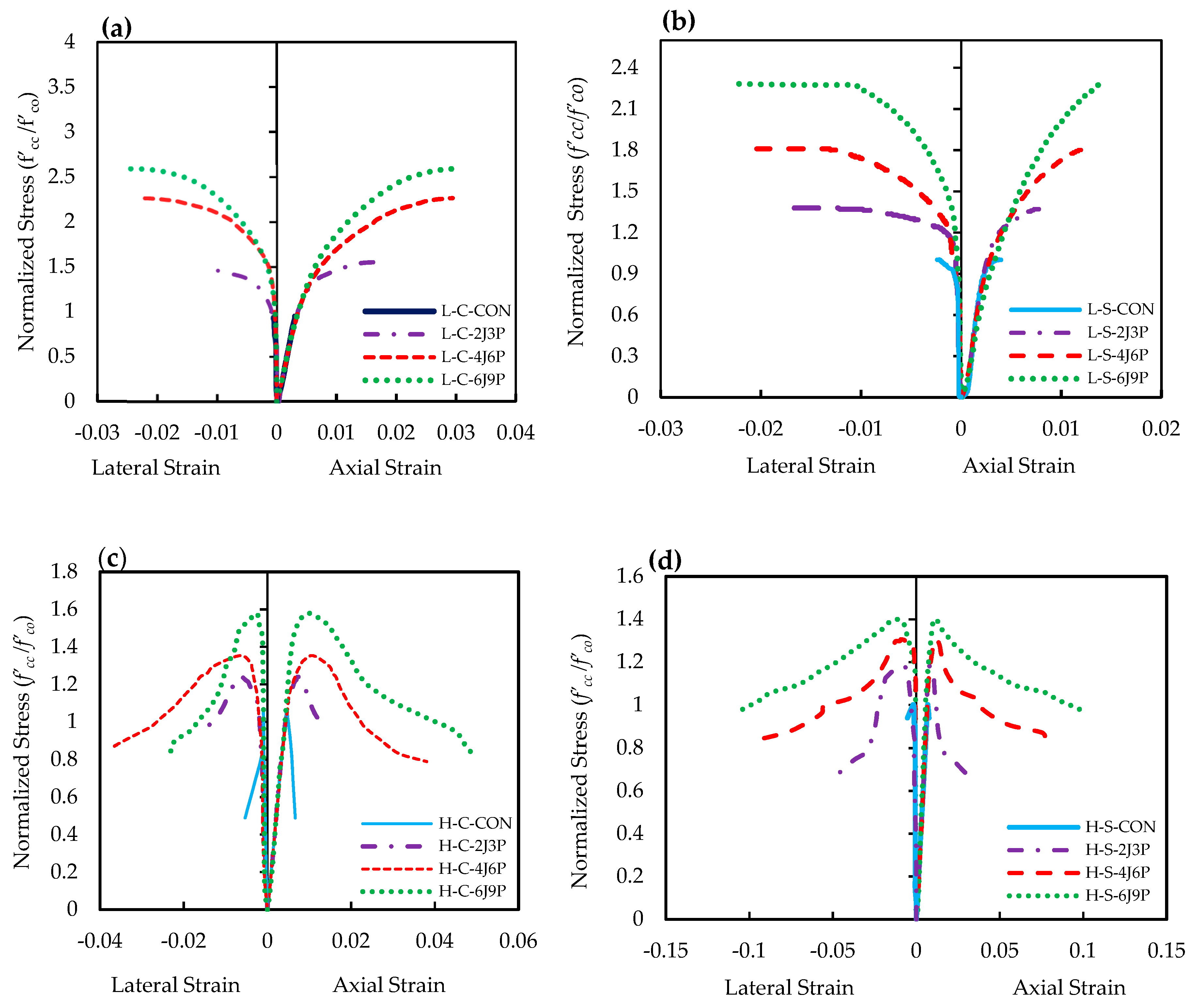
3.2. Stress-Strain Response

The observed test results are presented in terms of normalized axial compressive stress versus axial strain and normalized axial stress versus lateral strain curves, as shown in Figure 10a–d. Due to the difference in unconfined concrete compressive strengths (f′co), the compressive strength of JPFRP-confined concrete (
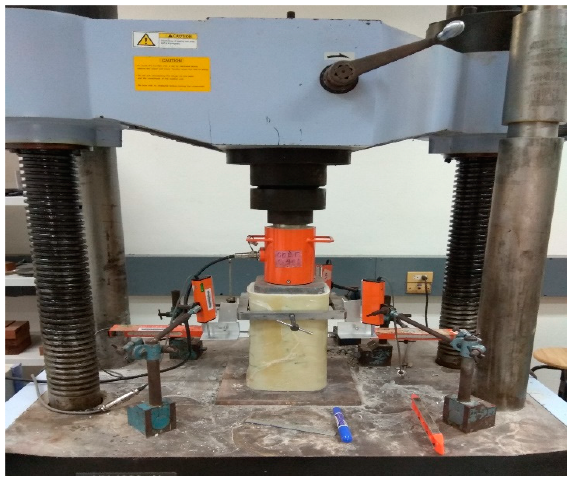
f′cc) for group (A, B, C, and D) is normalized by dividing it with the unconfined concrete strength, recorded for its corresponding batch and plotted against axial and lateral strain to clearly understand the effects of the considered parameters. The stress results were obtained by a load cell, whereas the strain values were derived from the LVDTs linked to the computer via a data acquisition system. LVDTs were able to record the deformation of the confined concrete columns until failure occurred. The average data of tested specimens are given in Table 6. Together, Figure 10a–d and Table 6 shows that the lateral jacketing with the hybrid JPFRP can improve the structural properties of confined concrete specimens, particularly ductility enhancement. No strain softening was observed for JPFRP-confined low-strength specimens, which demonstrates that the specimens were sufficiently confined. Similarly, Wu et al. [
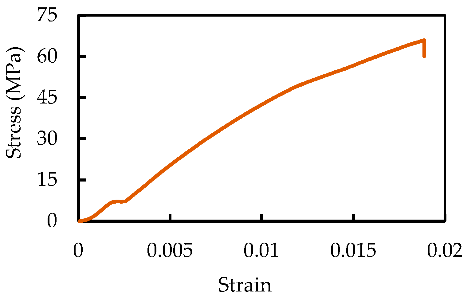
45] stated that enough lateral confinement of concrete specimens with a FRP sheet yields no strain softening behavior. The hybrid JPFRP-confined low-strength circular and square specimens showed bi-linear stress-strain behavior similar to the behavior of a sisal–glass hybrid FRP confinement of circular columns reported by [48]. The stress-strain curve of the hybrid JPFRP-confined specimens could be characterized into two main regions connected by a transitional zone. The first region of the stress-strain curve exhibits almost similar initial stiffness as that of an un-strengthened concrete specimen with peak stress (f′co) and axial strain (εco). In this region, JPFRP jacketing has less effect because of insignificant lateral deformation of the concrete core. When the level of applied stress reached the ultimate compressive strength of un-strengthened concrete specimens, a transitional zone appeared, indicated by the development of micro-cracks in the concrete core. Subsequently, the confinement effect of the JPFRP laminate was fully activated, thus the second part of the stress-strain curve of jacketed concrete columns showed a linear trend reaching the peak compressive strength (f′cc) with the corresponding compressive strain (εcc), and a reduced elastic modulus until the failure of the hybrid sheet. The second part is usually governed by the material properties of the FRP and the concrete. Ispir et al. [43] utilized two or more FRPs (such as glass, carbon, and PET) in hybrid confinement of circular concrete. The authors further studied the stress-strain behavior of these fibers in a different hybrid configuration; that is, they observed different types of mechanisms in hybrid FRP confined concrete: (1) inner and outer FRP sheet rupture at the same time and (2) fiber sheet having low elongation capacity will rupture first. Therefore, in the present study JPFRP sheets ruptured simultaneously in case of the low-strength specimens, and its stress-strain behavior is similar to the stress-strain curve of the hybrid-confined concrete specimens observed by [43,48]. However, the stress-strain curves of high-strength JPFRP-jacketed concrete columns showed a sudden load drop after reaching the peak compressive strength and decreased gradually until the ultimate strain of the specimens was reached. This phenomenon can be attributed to the dominance of the polyester fiber as it has a large rupture strain to accommodate the released energy after the breaking of the inner jute sheet. Similar behavior was previously observed by Huang et al. [49] for high-strength concrete specimens strengthened by polyester FRP. Furthermore, Rosakis [44] conducted experimental testing of low- and high-strength concrete jacketed with two or more different types of fibers with different elongation capacities (i.e., glass-FRP, vinylon, and polypropylene fiber ropes) in a hybrid configuration. The author observed a significant load drop after the inner GFRP sheet fractured and energy was released, however this energy was absorbed by fiber rope and enable the specimens to fail in a ductile manner. The load drop was significantly higher in high-strength concrete than low-strength jacketed specimens. Woldemariam et al. [53] used un-plasticized polyvinyl chloride (uPVC) tubes for concrete confinement; the authors observed similar load drops varying with the thickness-to-diameter ratio and concrete strength. A detailed description of the effects of the considered parameters is discussed in the next sections.

3.2.1. Circular Concrete Specimens

The results obtained from the experimental testing of all the specimens under concentric compression loadings are given in Table 6. Together Figure 10a–d and 
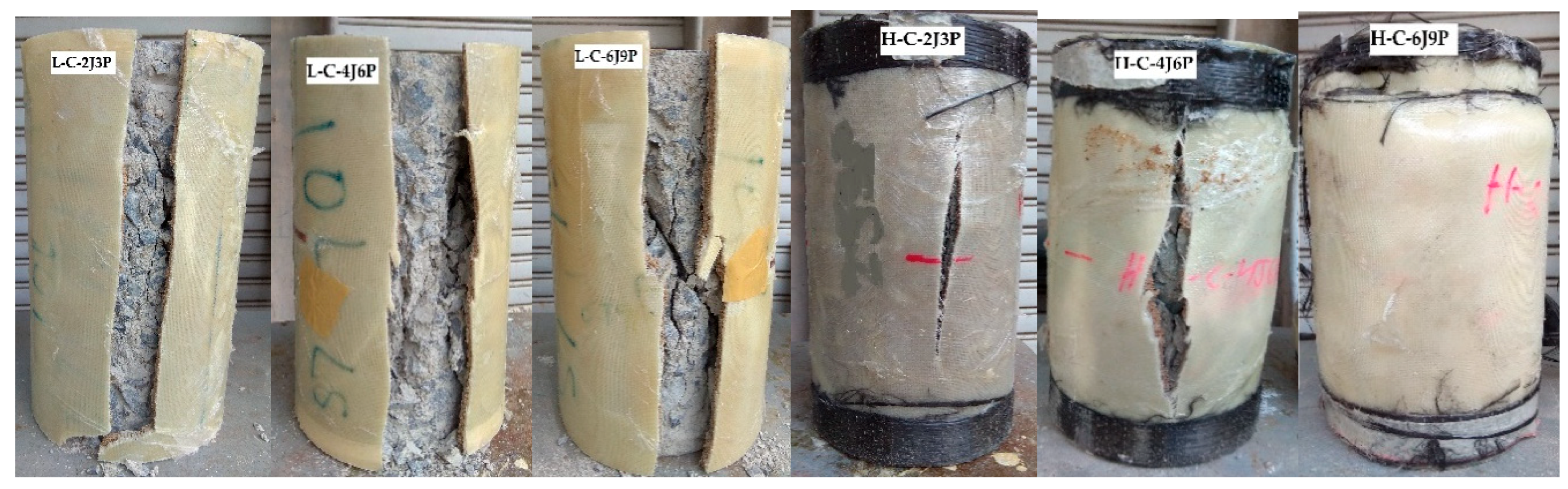
Table 6 imply that the hybrid confinement enhanced the overall response of low- and high-strength circular columns. The peak axial compressive strength and strain of the confined specimen increases with the increase in the number of FRP layers. Whereas the effectiveness of lateral jacketing is more dominant in low-strength circular concrete than high-strength circular concrete columns. The increase in the JPFRP plies increased the axial strength and strain of the circular concrete columns. This reflects that the thicker the JPFRP shell, the larger will be the peak compressive stress as well as ultimate strain. For low-strength circular specimens, when the number of JPFRP layers increased from 5 to 10, a substantial increase in both peak strength and strain was observed. However, when the JPFRP plies were increased from 10 to 15, a less significant enhancement was observed. The axial strength and strain of the specimen L-C-2J3P increased to 47% and 300%, respectively, compared to the unconfined reference concrete column. When the number of layers was increased to 10, for specimen L-C-4J6P, a substantial increase in axial strength and strain was recorded, that is, 127% and 753%, respectively. For the specimen L-C-6J9P, having 15 layers of confinement with a thickness of 5.28 mm, the highest compressive stress of 161% and axial strain of 797% was achieved. Previous studies highlighted that the effectiveness of lateral wrapping with FRP is more significant in low-strength concrete columns as compared to high-strength concrete columns [55,56]. In the case of JPFRP-confined high-strength circular specimens, it is evident from Figure 9 and Table 6 that the enhancement in compressive strength and strain is higher in low-strength JPFRP-confined concrete columns. The specimen H-C-2J3P displayed a 24% and 89% rise in the peak axial compressive strength and strain, respectively. The 10-layer specimen, H-C-4J6P with the JPFRP thickness of 3.52 mm, showed an enhancement of 35% and 135% in terms of axial compressive stress and strain, respectively. The 15-layer specimen H-C-6J9P exhibited an improvement of 58% and 93% in peak strength and strain, respectively.

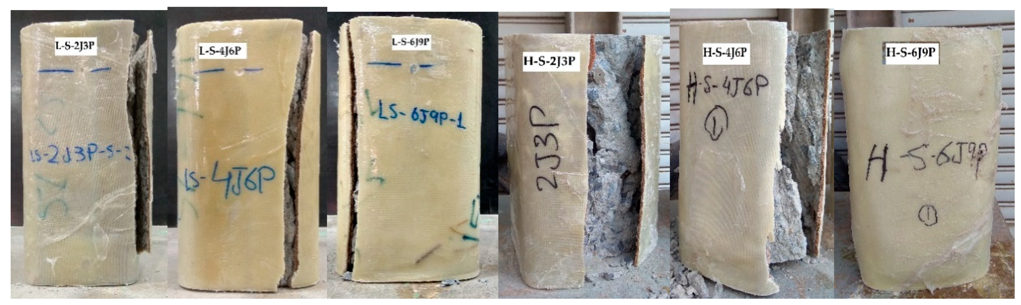
3.2.2. Square Concrete Specimens

The typical stress versus strain response of JPFRP-confined square concrete columns are shown in Figure 10b,d. The mean values obtained from the experimental testing are given in Table 6. Test results showed that the jacketed high-strength square specimens exhibited a remarkable enhancement in its load carrying capacity along with axial deformability. From 
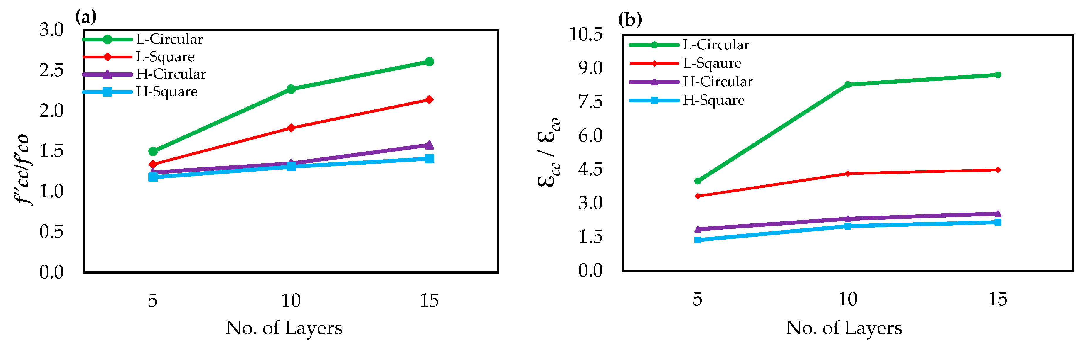
Figure 10b,d it was also observed that the increase in the number of JPFRP plies enhances the peak compressive strength and strain of the confined concrete. For example, the specimen L-S-2J3P with five FRP layers having a shell thickness of 1.76 mm failed at 34% higher strength and 233% higher axial strain as compared to the unjacketed square specimen. In the case of specimen L-S-4J6P, an increase of 79% and 333% was achieved in axial compressive strength and strain, respectively. The low-strength square concrete specimen, L-S-6J9P, achieved the highest axial stress and strain of 114% and 350%, respectively, compared to the un-jacketed concrete specimen. In contrast to the low-strength concrete column, the JPFRP-confined high-strength square column yields less improvement in the axial strength and strain. The high-strength specimen, H-S-2J3P, shown an increase of 18% in strength and 38% enhancement in axial strain. When the FRP layers were increased to 10, the specimen H-S-4J6P shown an increase of 31% in axial strength and a 100% increase in axial strain compared to the un-wrapped specimen. Similarly, the enhancement of 41% and 117% in strength and strain, respectively, was observed for the square concrete column, H-S-6J9P. Furthermore, the relation between the JPFRP layers and its effect on the normalized axial compressive strength and strain enhancement is graphically presented in Figure 11a,b. The figure clearly shows that the strength and strain of the confined concrete increased linearly with the increase in the number of JPFRP layers. However, the increase is significant in low-strength circular columns.
Overall, the improvement in axial compressive stress and strain of square specimens, especially high-strength specimens, are found to be less as compared to circular specimen because it has been observed in the previous literature that confining pressure is non-uniformly distributed in square specimens, decreasing the effectiveness of the FRP shell. In addition, confinement effectiveness is more pronounced in low-strength concrete columns than in high-strength concrete columns. The results of the present experimental study are in agreement with the findings of Chaallal et al. [57], as the authors observed an insignificant increase in compressive strength and strain of FRP-wrapped high-strength concrete columns. They stated that the deformation capacity of the high-strength concrete is less as compared to low-strength concrete, which results in a smaller lateral confining pressure.

3.3. Ductility and Fracture Energy of the JPFRP-Confined Specimens

Ductility can be described as the property of composite material, structural system, or structural element to withstand the inelastic deformation prior to the ultimate failure, without causing significant loss in structural resistance. Ductility is offered by the steel bars in the conventional reinforced concrete structures, and it is well-defined as the ratio of the ultimate deformation to that of yield deformation [33,
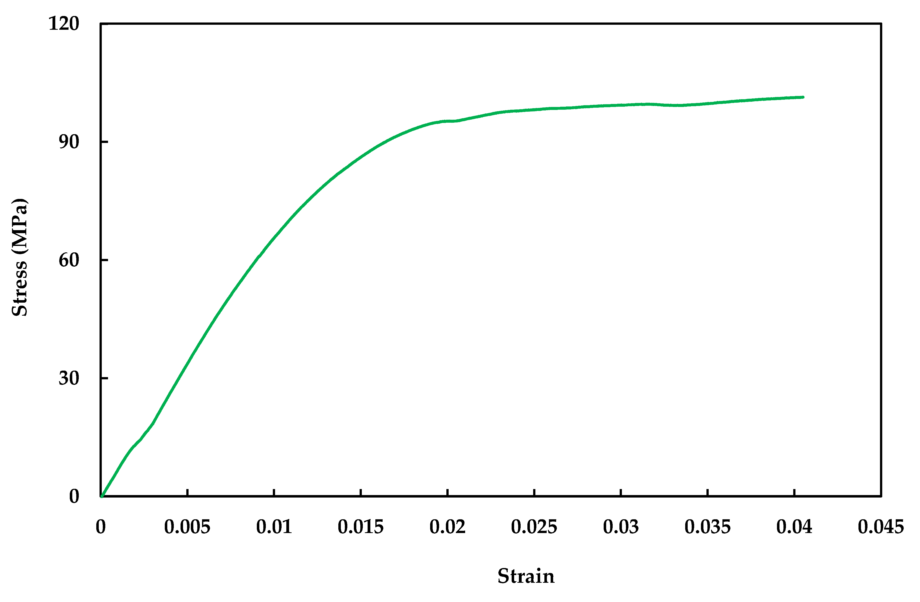
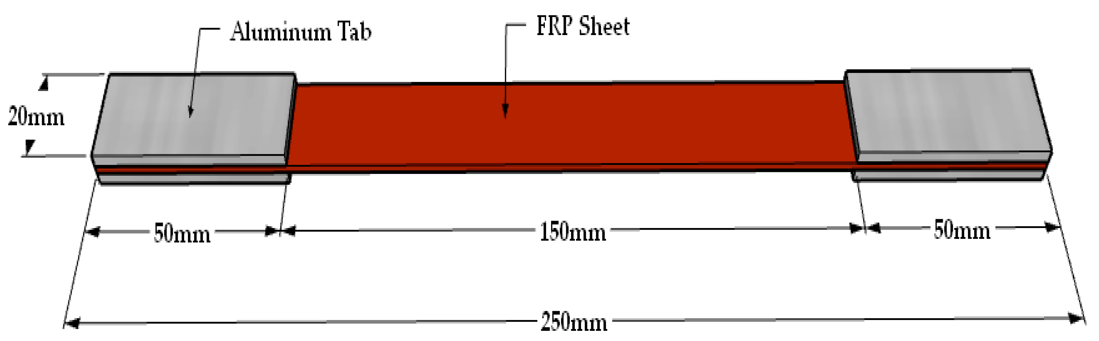
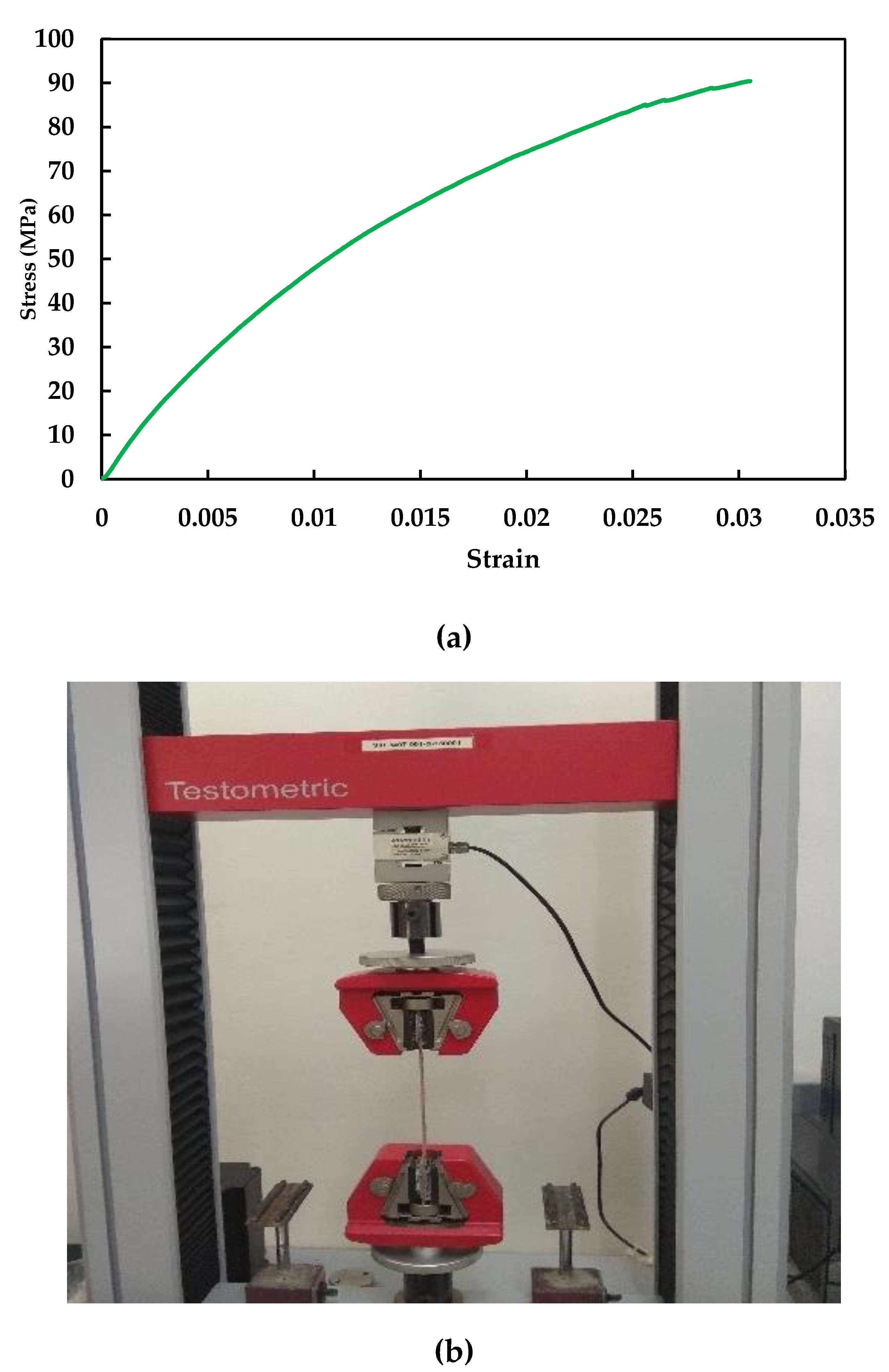
40]. Unlike steel reinforcement, which deforms significantly once it starts to yield, a jute–polyester hybrid FRP composite is elastic until failure, as shown in 
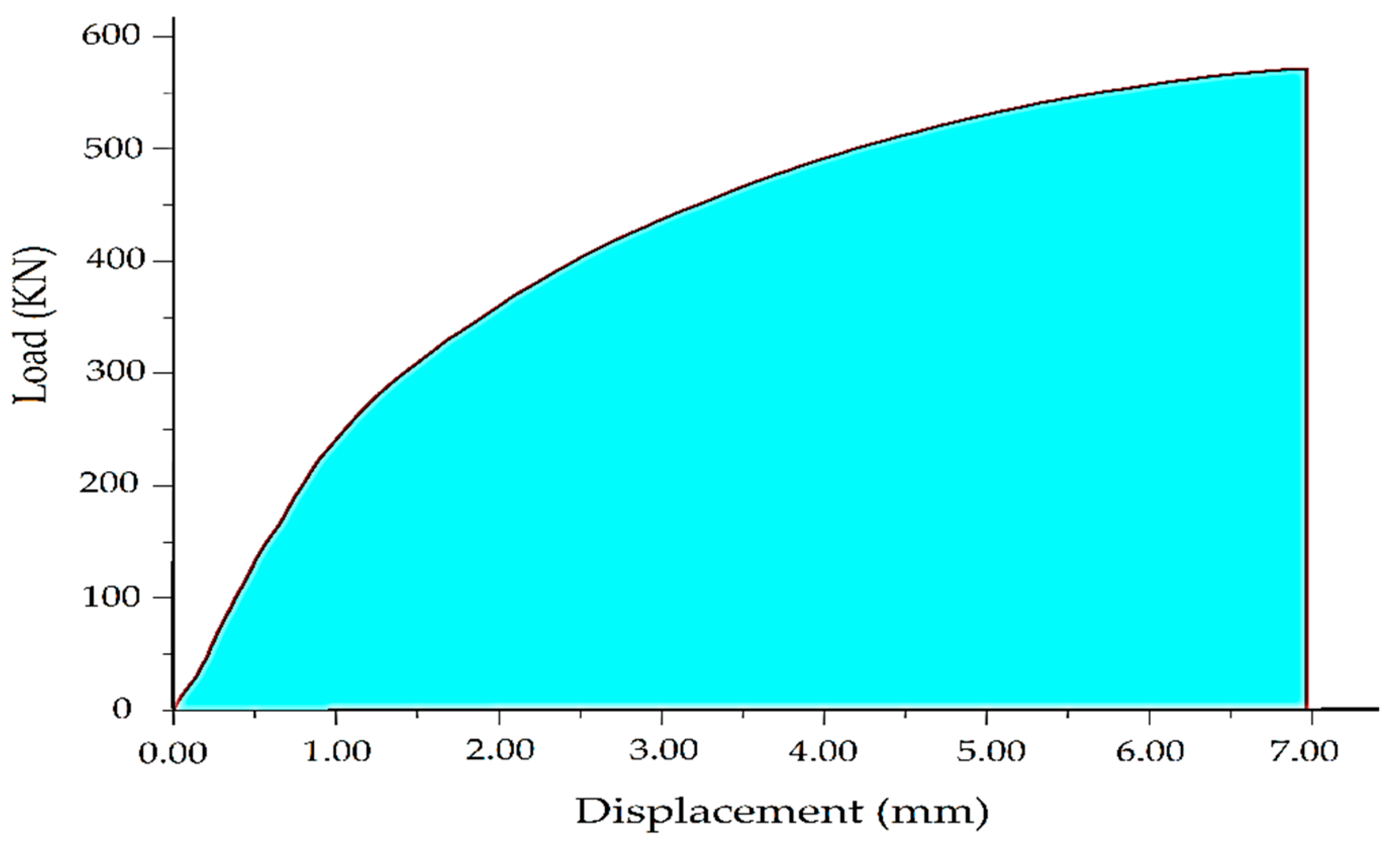
Figure 5a. Consequently, the necessity arises to find an appropriate method to assess the ductility of the JPFRP jacketed specimens. One approach towards the solution of this problem is to calculate the fracture energy of the JPFRP-confined concrete specimens and compare it with fracture energy of the unconfined specimen, represented as the energy ductility index. Fracture energy of a concrete specimen is defined as the energy absorbed by the concrete columns during breaking; this absorbed energy is equal to the area under load-displacement curve of concrete specimens having units of KN and mm, respectively, which leads to Nm [33]. The data analysis software OriginPro was used for the calculation of area under the load versus displacement curve, as graphically presented in Figure 12. The fracture energy and ductility index of all tested concrete specimens are given in Table 7. Apart from an increase in compressive strength, JPFRP wrapping can increase the fracture energy and ductility of the jacketed concrete specimens. It is concluded from Table 7 that JPFRP-confined concrete specimens exhibited a significant increase in fracture energy as compared with the control specimen. In addition, the energy absorption is highly reliant on the amount of JPFRP. Hence, the increase varies with the number of JPFRP plies, cross-sectional shape, and concrete strength. An enormous increase was observed in the fracture energy and ductility index of 5-, 10-, and 15-layer JPFRP-reinforced low-strength circular specimens in which the ductility index increased from 13.42 to 26.56. However, in high-strength, circular concrete specimens for the same number of layers the ductility index recorded is 4.94 to 14.56. Very high fracture energy was recorded for high-strength square specimens and its corresponding ductility index. The low-strength square specimens yield low fracture energy and its ductility index ranging from 4 to 10. The ductility index for 5-, 10- and 15-layer high-strength square specimens range from 5.20, 14.01, and 20.79, respectively.

3.4. Review of Strength and Strain Models

Since 1990s researchers have done extensive experimental and analytical work in developing several confinement models for the estimation of compressive strength and strain of FRP-strengthened circular, square, and rectangular concrete members tested under concentric loading. The majority of the proposed models have been derived by testing unreinforced concrete columns under uniaxial monotonic compression loadings. Few models were predicted by experimentally testing FRP wrapped reinforced concrete specimens. Most of the confinement models are based on empirical investigation; these models can further be divided into two types, design-oriented and analysis-oriented models [58]. In design-oriented models, the compressive stress and strain of FRP-strengthened concrete columns are estimated by the regression analysis of the test data obtained from the experiments [58,59,60]. An increasing type of axial compressive stress versus strain curve was predicted by most of these design-oriented models. The second type is an analysis-oriented model in which the stress-strain response of the FRP-confined concrete column is predicted by using an incremental numerical technique. As stated by Lam and Teng [61], the stress-strain behavior of effectively confined circular or square concrete columns is usually characterized by a parabolic curve, consisting of two main segments ascending linearly. The first portion displays an ascending parabolic curve almost similar to that of un-strengthened concrete, linked with the second linear segments through an even transition zone. In the first region, the FRP reinforcement provides insignificant effects on the lateral confinement of the concrete core. However, the second linear segment of the curve is significantly influenced by the FRP wrapping, type of FRP material, shape of cross-section, and concrete strength. This part stretches continuously until the failure of the specimens occurs.
To achieve a reliable design, it is very important that the existing models should accurately predict the strength and axial strain of FRP-jacketed specimens. Currently, numerous stress-strain models are available to predict the axial compressive stress and strain of different types of FRP-jacketed circular and non-circular concrete columns [14,18,23,57,58,60,61,62].

3.4.1. Existing Strength Models

Most of the existing stress models, developed for different types of FRP-jacketed concrete members employ the following general form:
f c c f c o = 1 + k 1 f l f c o
where the compressive strength of the confined specimen is denoted by f c c and the compressive strength of the unconfined specimen is denoted by f c o ; k 1 is the confinement effectiveness coefficient while the lateral confining pressure of the FRP jacket is represented by f l . This equation was originally proposed by Richart et al. [63] for an active confinement of concrete by fluid with k 1 = 4.1. Subsequently, Richart et al. [64] stated that the use of this strength model can be extended for steel-confined concrete. Later, experimental studies were conducted by Fardis and Khalili [65], they suggested that the model proposed by Richart et al. can be used for fiber reinforced polymers confined concrete. The lateral confining pressure could be directly correlated to the volumetric ratio and the tensile strength of FRP composite as follows:
For circular specimens,
f l = 2 · E f r p · t · ε l D
f f r p = E f r p · ε l
f l = 2 f f r p t D
where E f r p is the elastic modulus of FRP; ε l , and f f r p are the lateral strain and tensile strength of FRP sheet, respectively; t represents the thickness of the FRP; and D represents the diameter of the jacketed circular columns.
For square specimens,
f l = 2 f f r p t D k s
where the diagonal length of the square concrete column is represented by D. For square cross-sections with rounded shaped corners ( r c ), D can be given as
D = 2   b 2 r c ( 2 1 )
and where ks is the shape factor. Masia et al. [66] and Pessiki et al. [67] defined shape factor as the ratio of the effective confined area Ac, to the total cross-sectional area of concrete expressed in terms of gross-sectional area Ag, expressed as
k s = A c A g
By limiting the Pessiki et al. [66] expression to plain concrete and square cross-sections allows k s to be defined as a function of corner-radius ( r c ) and cross-section dimension (b) as
k s = 1 2 3 [ ( 1 2 r c b ) 2 1 ( 4 π ) ( r c b ) 2 ]

3.4.2. Existing Strain Models

Previous studies suggested that in steel-jacketing concrete, the axial strain ε c c achieved at the corresponding compressive strength can be directly associated with the confining pressure of FRP [63]. The expression can be written as
ε c c = ε c o ( 1 + k 2 f l f c o )
where ε c c symbolizes peak strain of the jacketed concrete specimens corresponding to the peak strength f c c , ε c o denotes the strain of unconfined concrete, and k 2 is the experimentally determined confinement coefficient. Richart et al. [63] proposed the value of k 2   equal   to   5 k 1 for concrete jacketed by steel reinforcement. Researchers have proposed different k values ranging from 2 to 15, based on different parameters such as types of concrete and the spacing between spiral reinforcement. Later, for FRP wrapped concrete, researchers proposed that the lateral confining pressure can also be associated with the axial strain. Table 7 shows the selected strain models from the available literature.

3.5. Evaluation of Strength and Strain Models

The test data obtained from the experimental program of the current study were used to evaluate the effectiveness of the several existing strength and strain models in predicting the peak axial strength and strain of the JPFRP-confined circular and square concrete specimens. The selected stress-strain models for circular and non-circular columns are given in Table 8 and Table 9, respectively. These include the models of [18,36,48,49,55,58,59,61,65,68,69,70,71].
Huang et al. [49] proposed a stress-strain model by using the experimental results obtained from circular polyester FRP-wrapped concrete specimens. The unreinforced concrete strength ( f c o ) ranged from 22.1 to 39.3 MPa. The expression is given in Table 8, where f l represents the lateral confining pressure which is equal to ( 2 · E f r p · t · ε l ) / D ; here E f r p is the elasticity modulus of polyester jacket and t denotes PFRP thickness. The lateral strain of the PFRP jacket is denoted by ε l and the diameter of the specimen is denoted by D.
The model of Karbhari and Gao [59] is based on the analytical study of three data sets, which includes the test results of [16,75], and the author’s experimental results obtained from testing of 15 axially loaded CFRP and glass-aramid FRP-confined concrete columns in developing this model. The derived strength model is based on the model in [76]. However, it differs in confinement coefficients.
Pimanmas et al. [36] developed stress-strain models for sisal FRP-confined circular and square concrete columns. The model is applicable for both low- and high-strength concrete specimens with circular and square sections. The lateral confining pressures were calculated by f l = 2 f f r p t / D for circular section and f l = ( 2 f f r p t / D ) k s for square section, where f f r p is the tensile strength of the FRP-composite jacket obtained by tensile coupon test; t represent total thickness of the FRP-laminate; while the diameter of the circular section is represented by D, or it is the diagonal length of the square section; shape factor is represented by k s , determined by Equation (8).
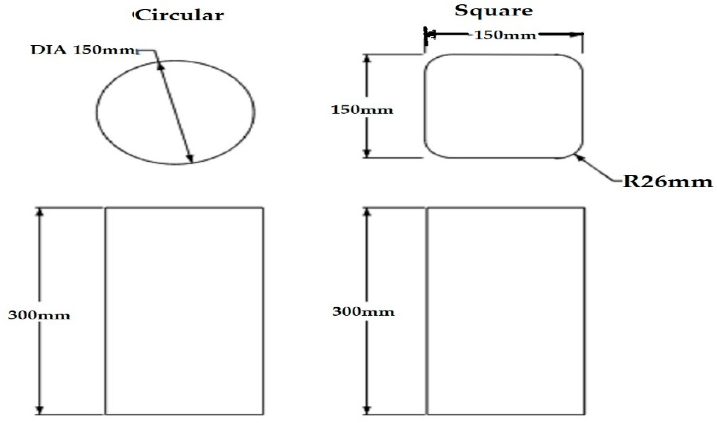
Ilki et al. [72] established stress and strain models based on the test data of CFRP-wrapped circular concrete columns. The strength of the ready-mixed concrete used in the preparation of concrete columns was 6.2 MPa. The experimental program includes the testing of 14 circular concrete columns having dimensions of 150 mm × 300 mm, under axial compression. The expressions are given in Table 8. The effective lateral confining pressure f l was determined by the equation 2 n s f t / D .
The proposed strength and strain model of Lam and Teng 2002 [61] was established by the statistical analysis of the test database compiled from the existing literature. The database included over 200 test results of plain circular concrete jacketed by CFRP, GFRP, and aramid FRP. The unconfined concrete strength ranged between 26 and 55 MPa. Based on the statistical analysis of the test data set, the authors concluded that there exists a direct correlation between the compressive stress of FRP-jacketed concrete and the lateral confining pressure of FRP-laminate. Lam and Teng [58] proposed another stress-strain model, based on the analysis of test results obtained from their experiments as well as from the test database they compiled from the available literature. Their experimental program included the testing of CFRP-wrapped square and rectangular concrete specimens. The strength of unconfined concrete specimens ranged between 23.8 and 44 MPa. The proposed expression for the square section is given in Table 9. Shape factor k s is incorporated for the stress-strain models of square concrete sections.
Padanattil et al. [48] analyzed the experimental results obtained from the axial compressive testing of sisal–glass hybrid FRP-jacketed circular columns and proposed a strength model, presented in Table 8. The axial strength of unwrapped concrete was 21.1 MPa. Fifty circular concrete columns having dimensions of 100 mm × 200 mm were tested under concentric axial compression loads. Equation (4) was used to determine the lateral confining pressure of hybrid FRP composite.
The model of Kumutha et al. [18] was developed for GFRP-confined rectangular concrete columns. The unconfined concrete strength was approximately 27.45. A total of nine reinforced concrete specimens were experimentally analyzed under concentric compression loading. Moreover, shape factor was incorporated because of the non-circular shape. The proposed equation is given in Table 9.
Shehata et al. [69] carried out experimental testing of CFRP-wrapped concrete columns with different cross-sectional shapes that is circular, square, and rectangular. Based on test results, the author established strength and strain models for the aforementioned cross-sectional shapes. The axial compressive strength of the un-jacketed concrete varied between 23.7 to 29.7 MPa. The corners were rounded to 10 mm for square and rectangular columns. The expression is given in Table 9; the lateral confining pressure is derived by using Equation (2).
Using the test results obtained from CFRP-confined square specimens, Al-Salloum [70] proposed an expression for compressive stress of CFRP-wrapped concrete specimens. The unconfined concrete strength ranged between 32 and 35 MPa. Sixteen square concrete columns with different corner radii, having a breadth and depth of 150 mm, were tested under the effect of axial compressive loading until the failure of specimens. The proposed model is given in Table 9. A modification factor (b/d) was introduced to counter the non-uniformity of the confining pressure. Where, b is the section dimension, and D is the length of the diagonal of the square concrete column, calculated by Equation (6).
A unified strength and strain model was developed by Wei and Wu [71] for different cross-sectional shapes. This proposed expression was established by analyzing a large test database of AFRP, CFRP, and GFRP-jacketed circular, square, and rectangular concrete specimens having an un-jacketed compressive strength between 18 and 55 MPa. The reported corner radius in the test database varied between 0–60 mm. In the proposed expression, given in Table 9, (h/b) is the cross-section aspect ratio; f 30 is the un-confined concrete strength of grade C30.
The performance of these given models (Table 8 and Table 9) in predicting the peak axial compressive strength ( f c c ) and axial strain ( ε c c ) of JPFRP-jacketed circular and square columns are assessed by using the experimental data of the present study. These predicted values are then compared with the test results recorded in the present study in the form of predicted ratio experimental results ( f c c ) p / ( f c o ) e , and ( ε c c ) p / ( ε c c ) e for strength and strain, respectively. Table 10 and 
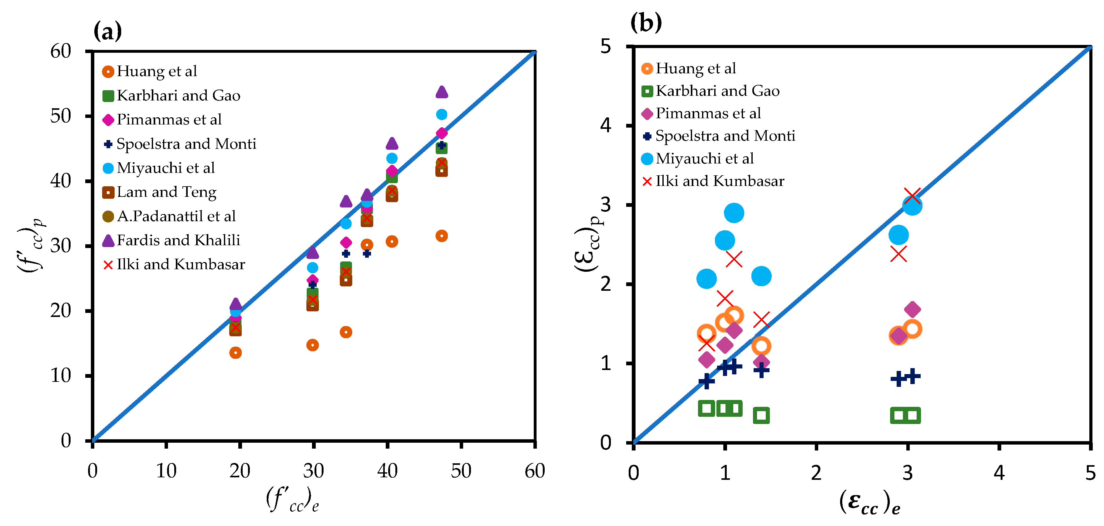
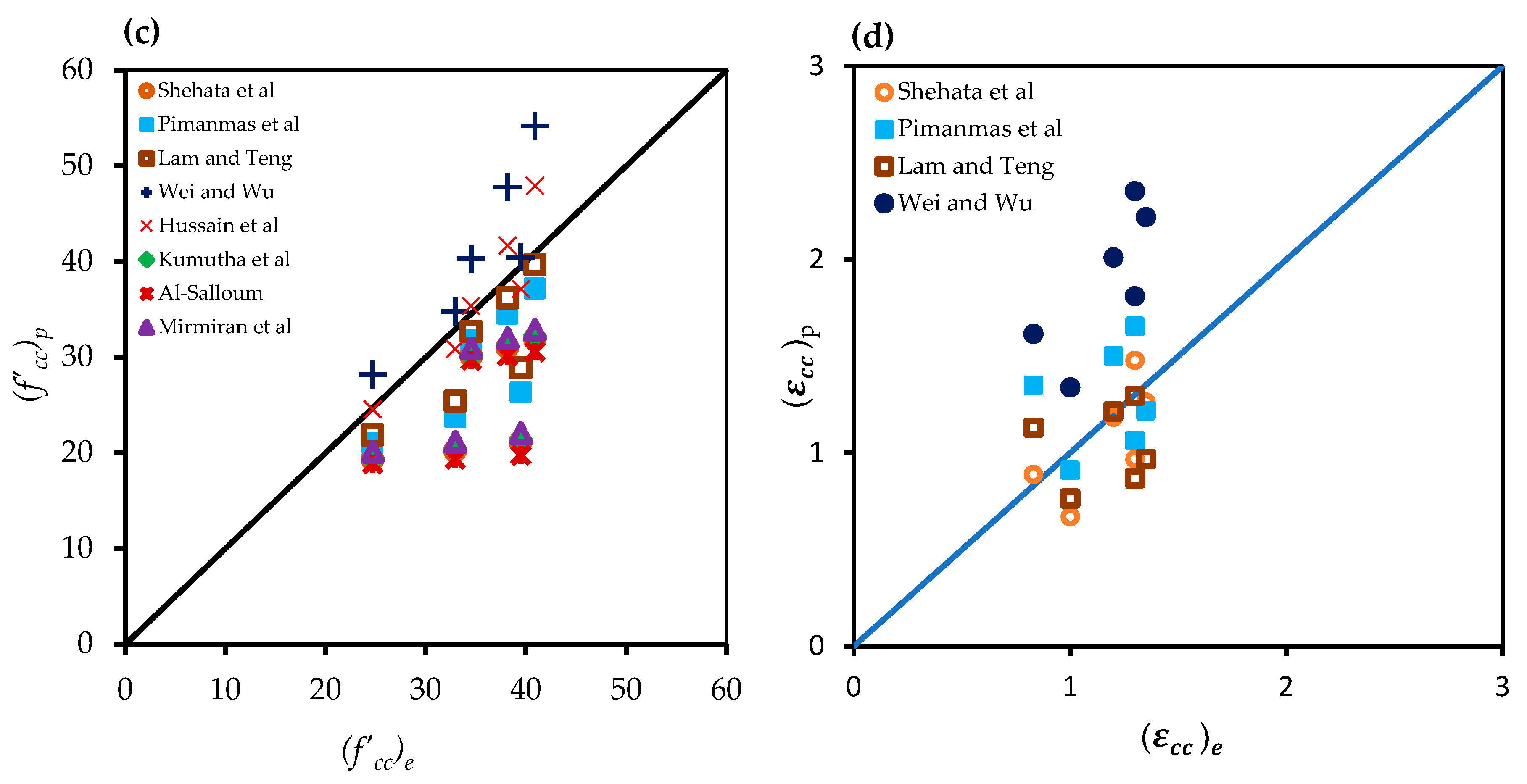
Table 11 show the predicted values of axial stress and strain ratios. Moreover, the performance comparison between the predicted values from stress-strain models and the experimental results are graphically presented in Figure 13a–d, in which the models predicted values below the line of equality, indicating the underestimation, while the predicted values above the equality line imply overestimation. Furthermore, the statistical performance of the given existing models are mentioned in Table 12 and Table 13 in the form of ( f c c ) p / ( f c o ) e and ( ε c c ) p / ( ε c c ) e .
The performance of the aforementioned strength and strain models in predicting the stress and strain of the JPFRP-wrapped specimens of the current study was further assessed in terms of statistical indicators such as average values, standard deviation (SD), coefficient of variation (COV), and average absolute error (AAE), presented in Equations (10)–(13), respectively:
Mean = 1 n i n ( Predicted Experimental ) i ,
SD = 1 n i = 1 n ( ( Predicted Experimental ) i Mean ) 2 ,
COV = Standard   Deviation Mean × 100 ,
AAE = 1 n i = 1 n | Predicted Experimental Experimental | × 100 .
From Figure 13a and Table 12 it can be observed that the model of [49] highly underestimate the compressive strength of JPFRP-wrapped circular concrete with an AAE of 56.84%, although the variation in the data was less than 20%. The model of [73] accurately predicted the compressive strength with an AAE of 1.17%. Moreover, the models of [36,59,65], predicted the compressive strength of the circular columns reasonably close, with an AAE of 6.02%, 6.86%, and 9.40%, respectively. The strength models of [48,61,68,72], also performed better with an AAE of less than 20%. Furthermore, for strain models of circular specimens, Figure 13b shows very scattered data points, reflecting that almost all the strain models either underestimate or overestimate the experimental results. However, the strain models of [49,72] predicted the strain values slightly closer to the experimental strain values with an AAE of 17.84% and 21.27%, respectively. Similarly, Table 12 and Figure 13c exemplifies that the strength model of [55] accurately predicts compressive strength for square columns. The models of [36,58] provide underestimation with an AAE of less than 20%. On the other hand, the model of [71] provides overestimation with an AAE of 14.44%. The stress-strain models of [69] predicted the strength and strain values with an AAE of 30% and 24%, respectively. The strength models of [18,70,74], predicted the axial strength with an AAE of around 30%. Table 13 and Figure 13d show that the strain models of square specimens show better results as compared with the strain models of circular specimens. The model of [71] provides high overestimation with an AAE of 36.07%. The model of [36] considered the parameter of corner radius and strength for square specimens. Thus, their strain model performed reasonably well with an AAE of 10.13%.

4. Conclusions

This paper attempted an experimental and analytical investigation of jute–polyester hybrid FRP (JPFRP) confinement of circular and square standard concrete specimens to assess its suitability and structural performance. For this purpose, 32 concrete specimens were tested by applying monotonic axial compressive loading until failure. Based on the experimental results of this study and analytical evaluation, the following conclusions are made:
  • The tensile testing of jute FRP composite exhibited a linear stress-strain response, whereas the polyester FRP composite displayed a bi-linear stress-strain behavior. In turn, the testing of hybrid jute–polyester FRP composite showed a bi-linear stress-strain response, with an ascending parabolic shape.
  • The JPFRP hybrid confinement is effective in improving the compressive strength and strain capacity of both circular and non-circular specimens. The increase in strength and ultimate strain is directly dependent on the increasing number of FRP layers.
  • The efficacy of the JPFRP in providing external confinement is more dominant in concrete specimens having low-strength and a circular cross-section as compared to specimens with high-strength and a square cross-sectional shape.
  • The stress-strain response in high-strength specimens was dominated by the large strain behavior of polyester FRP. The inner FRP sheet ruptures after reaching the peak strength; afterward, the outer FRP sheet provides enough resistance to the lateral expansion of the concrete core, until it reaches the ultimate state.
  • The hybrid confined significantly enhanced the fracture energy and ductility index of the confined concrete. The increase in fracture energy and ductility index varies with the number of FRP layers and concrete strength. In addition, the external jacketing helped the concrete columns to bear the load for long period of time after reaching the peak axial load. This phenomenon was more dominantly observed in high-strength specimens, which results in a ductile failure.
  • The majority of the existing strength and strain models derived for conventional FRP-jacketed concrete underestimated the compressive strength of the JPFRP-confined specimens. The best prediction of compressive strength was made by the models of [55,73]. However, the prediction of strain models was far from the experimental values.
  • The hybrid-confinement can be used to protect the spalling of the concrete cover and prevention of moisture penetration. In addition, it can be used in an earthquake-prone area, where low to moderate strength and high ductility is required.

Author Contributions

Conceptualization, N.W. and P.S.; data curation, N.W.; formal analysis, N.W.; funding acquisition, N.W. and P.S.; investigation, N.W.; methodology, N.W.; project administration, P.S.; software, N.W.; supervision, P.S.; validation, P.S., Q.H. and P.C.; writing—original draft, N.W.; and writing—review and editing, P.S., Q.H. and P.C.

Funding

This research was funded by the Faculty of Engineering, Kasetsart University, Bangkok, Thailand.

Acknowledgments

The authors would like to express their gratitude to Thongchai Rohitatisha, Project Director, Sustainable Energy and Resources Engineering (SERE) program for his administrative support. Thanks, are also extended to the staff of structural engineering laboratory, Asian Institute of Technology.

Conflicts of Interest

The authors declare no conflict of interest.

References

  1. References Júlio, E.S.; Branco, F.; Silva, V.D. Structural rehabilitation of columns with reinforced concrete jacketing. Prog. Struct. Eng. Mater. 2003, 5, 29–37. [Google Scholar] [CrossRef] [Green Version]
  2. Bossio, A.; Imperatore, S.; Kioumarsi, M. Ultimate Flexural Capacity of Reinforced Concrete Elements Damaged by Corrosion. Buildings 2019, 9, 160. [Google Scholar] [CrossRef]
  3. El Maaddawy, T. Strengthening of Eccentrically Loaded Reinforced Concrete Columns with Fiber-Reinforced Polymer Wrapping System: Experimental Investigation and Analytical Modeling. J. Compos. Constr. 2009, 13, 13–24. [Google Scholar] [CrossRef]
  4. Rodriguez, M.; Park, R. Repair and Strengthening of Reinforced Concrete Buildings for Seismic Resistance. Earthq. Spectra 1991, 7, 439–459. [Google Scholar] [CrossRef]
  5. Xiao, Y.; Wu, H. Compressive Behavior of Concrete Confined by Carbon Fiber Composite Jackets. J. Mater. Civ. Eng. 2000, 12, 139–146. [Google Scholar] [CrossRef]
  6. Toutanji, H.; Deng, Y. Strength and durability performance of concrete axially loaded members confined with AFRP composite sheets. Compos. Part B Eng. 2002, 33, 255–261. [Google Scholar] [CrossRef]
  7. Triantafyllou, G.G.; Rousakis, T.C.; Karabinis, A.I. Axially Loaded Reinforced Concrete Columns with a Square Section Partially Confined by Light GFRP Straps. J. Compos. Constr. 2015, 19, 04014035. [Google Scholar] [CrossRef]
  8. Abbasnia, R.; Ziaadiny, H. Experimental investigation and strength modeling of CFRP-confined concrete rectangular prisms under axial monotonic compression. Mater. Struct. Mater. Et Constr. 2015, 48, 485–500. [Google Scholar] [CrossRef]
  9. Alsaad, A.; Hassan, G. Utilization of CFRP for strengthening RC columns in marine environment. Case Stud. Constr. Mater. 2017, 7, 30–35. [Google Scholar] [CrossRef]
  10. Cao, S.; Wu, Z.; Wang, X. Tensile properties of CFRP and hybrid FRP composites at elevated temperatures. J. Compos. Mater. 2009, 43, 315–330. [Google Scholar] [CrossRef]
  11. Chaallal, O.; Hassan, M.; Shahawy, M. Confinement model for axially loaded short rectangular columns strengthened with fiber-reinforced polymer wrapping. ACI Struct. J. 2003, 100, 215–221. [Google Scholar] [CrossRef]
  12. Iacobucci, R.D.; Sheikh, S.A.; Bayrak, O. Retrofit of Square Concrete Columns with Carbon Fiber-Reinforced Polymer for Seismic Resistance. ACI Struct. J. 2003, 100, 785–794. [Google Scholar] [CrossRef]
  13. Önal, M.M.; Zengin, B.; Koçak, A.; Doran, B. An experimental investigation on flexural behavior of RC beams strengthened with different techniques. KSCE J. Civ. Eng. 2014, 18, 2162–2169. [Google Scholar] [CrossRef]
  14. Turgay, T.; Köksal, H.O.; Polat, Z.; Karakoc, C. Stress-strain model for concrete confined with CFRP jackets. Mater. Des. 2009, 30, 3243–3251. [Google Scholar] [CrossRef]
  15. Saadatmanesh, H.; Ehsani, M.R.; Li, M.W. Strength and Ductility of Concrete Columns Externally Reinforced with Fiber Composite Straps. ACI Struct. J. 1994, 91, 434–447. [Google Scholar]
  16. Nanni, A.; Bradford, N.M. FRP jacketed concrete under uniaxial compression. Constr. Build. Mater. 1995, 9, 115–124. [Google Scholar] [CrossRef]
  17. Benzaid, R.; Chikh, N.E.; Mesbah, H. Behaviour of square concrete column confined with GFRP composite warp. J. Civ. Eng. Manag. 2008, 14, 115–120. [Google Scholar] [CrossRef]
  18. Kumutha, R.; Vaidyanathan, R.; Palanichamy, M.S. Behaviour of reinforced concrete rectangular columns strengthened using GFRP. Cem. Concr. Compos. 2007, 29, 609–615. [Google Scholar] [CrossRef]
  19. Toutanji, H.A. Durability characteristic of concrete columns confined with advanced composite materials. Compos. Struct. 1999, 44, 155–161. [Google Scholar] [CrossRef]
  20. Vincent, T.; Ozbakkaloglu, T. Compressive Behavior of Prestressed High-Strength Concrete-Filled Aramid FRP Tube Columns: Experimental Observations. J. Compos. Constr. 2015, 19, 4015003. [Google Scholar] [CrossRef]
  21. Wang, Y.-F.; Wu, H.-L. Size Effect of Concrete Short Columns Confined with Aramid FRP Jackets. J. Compos. Constr. 2011, 15, 535–544. [Google Scholar] [CrossRef]
  22. Anggawidjaja, D.; Ueda, T.; Dai, J.; Nakai, H. Deformation capacity of RC piers wrapped by new fiber-reinforced polymer with large fracture strain. Cem. Concr. Compos. 2006, 28, 914–927. [Google Scholar] [CrossRef]
  23. Dai, J.-G.; Bai, Y.-L.; Teng, J.G. Behavior and Modeling of Concrete Confined with FRP Composites of Large Deformability. J. Compos. Constr. 2011, 15, 963–973. [Google Scholar] [CrossRef]
  24. Dai, J.-G.; Lam, L.; Ueda, T. Seismic retrofit of square RC columns with polyethylene terephthalate (PET) fibre reinforced polymer composites. Constr. Build. Mater. 2012, 27, 206–217. [Google Scholar] [CrossRef]
  25. Ispir, M. Monotonic and Cyclic Compression Tests on Concrete Confined with PET-FRP. J. Compos. Constr. 2015, 19, 04014034. [Google Scholar] [CrossRef]
  26. Saleem, S.; Hussain, Q.; Pimanmas, A. Compressive Behavior of PET FRP–Confined Circular, Square, and Rectangular Concrete Columns. J. Compos. Constr. 2017, 21, 04016097. [Google Scholar] [CrossRef]
  27. Campione, G.; La Mendola, L.; Monaco, A.; Valenza, A.; Fiore, V. Behavior in compression of concrete cylinders externally wrapped with basalt fibers. Compos. Part B Eng. 2015, 69, 576–586. [Google Scholar] [CrossRef]
  28. Colombo, C.; Vergani, L.; Burman, M. Static and fatigue characterisation of new basalt fibre reinforced composites. Compos. Struct. 2012, 94, 1165–1174. [Google Scholar] [CrossRef]
  29. Suon, S.; Saleem, S.; Pimanmas, A. Compressive behavior of basalt FRP-confined circular and non-circular concrete specimens. Constr. Build. Mater. 2019, 195, 85–103. [Google Scholar] [CrossRef]
  30. Tanaka, T.; Yagi, K.; Kojima, N.; Kimura, K.; Katsumata, H. Retrofit method with carbon fiber for reinforced concrete structures. Adv. Compos. Mater. 1994, 4, 73–85. [Google Scholar] [CrossRef]
  31. Li, J.; Qian, J.; Jiang, J. Experimental investigation on axial compressive behavior of FRP confined concrete columns. In Proceedings of the International Conference on Advances in Building Technology, Hong Kong, China, 4–6 December 2002. [Google Scholar]
  32. Bakis, C.E.; Bank, L.C.; Brown, V.; Cosenza, E.; Davalos, J.F.; Lesko, J.J.; Machida, A.; Rizkalla, S.H.; Triantafillou, T.C. Fiber-Reinforced Polymer Composites for Construction—State-of-the-Art Review. J. Compos. Constr. 2002, 6, 73–87. [Google Scholar] [CrossRef]
  33. Yan, L.; Chouw, N. Natural FRP tube confined fibre reinforced concrete under pure axial compression: A comparison with glass/carbon FRP. Thin-Walled Struct. 2014, 82, 159–169. [Google Scholar] [CrossRef]
  34. Ghalieha, L.; Awwad, E.; Saad, G.; Khatib, H.; Mabsoute, M. Concrete Columns Wrapped with Hemp Fiber Reinforced Polymer–An Experimental Study. In Proceedings of the 3rd International Conference on Natural Fibers: Advanced Materials for a Greener World, ICNF, Braga, Portugal, 21–23 June 2017. [Google Scholar]
  35. Siriluk, S. Behaviours of Rc Deep Beams Strengthened in Shear Using Hemp Fiber Reinforced Polymer Composites. Int. J. Geomate 2018, 15, 89–94. [Google Scholar] [CrossRef]
  36. Pimanmas, A.; Hussain, Q.; Panyasirikhunawut, A.; Rattanapitikon, W. Axial strength and deformability of concrete confined with natural fibre-reinforced polymers. Mag. Concr. Res. 2019, 71, 55–70. [Google Scholar] [CrossRef]
  37. Sen, T.; Paul, A. Confining concrete with sisal and jute FRP as alternatives for CFRP and GFRP. Int. J. Sustain. Built Environ. 2015, 4, 248–264. [Google Scholar] [CrossRef] [Green Version]
  38. Sen, T.; Reddy, H.N.J. Efficacy of thermally conditioned sisal FRP composite on the shear characteristics of reinforced concrete beams. Adv. Mater. Sci. Eng. 2013, 2013, 1–14. [Google Scholar] [CrossRef]
  39. Gowda, T.M.; Naidu, A.C.B.; Chhaya, R. Some mechanical properties of untreated jute fabric-reinforced polyester composites. Compos. Part A Appl. Sci. Manuf. 1999, 30, 277–284. [Google Scholar] [CrossRef]
  40. Yan, L. Plain concrete cylinders and beams externally strengthened with natural flax fabric reinforced epoxy composites. Mater. Struct. 2015, 49, 2083–2095. [Google Scholar] [CrossRef]
  41. Ribeiro, F.; Sena-Cruz, J.; Júlio, E.; Branco, F. Axial Compressive Behaviour Of Hybrid FRP Confined Concrete. In Proceedings of the 9th International Conference on Fibre-Reinforced Polymer (FRP) Composites in Civil Engineering (CICE 2018), Paris, France, 17–19 July 2018. [Google Scholar]
  42. Bouchelaghem, H.; Bezazi, A.; Scarpa, F. Compressive behaviour of concrete cylindrical FRP-confined columns subjected to a new sequential loading technique. Compos. Part B Eng. 2011, 42, 1987–1993. [Google Scholar] [CrossRef]
  43. Ispir, M.; Dalgic, K.D.; Ilki, A. Hybrid confinement of concrete through use of low and high rupture strain FRP. Compos. Part B Eng. 2018, 153, 243–255. [Google Scholar] [CrossRef]
  44. Rousakis, T.C. Hybrid Confinement of Concrete by Fiber-Reinforced Polymer Sheets and Fiber Ropes under Cyclic Axial Compressive Loading. J. Compos. Constr. 2013, 17, 732–743. [Google Scholar] [CrossRef]
  45. Wu, G.; Wu, Z.S.; Lu, Z.T.; Ando, Y.B. Structural Performance of Concrete Confined with Hybrid FRP Composites. J. Reinf. Plast. Compos. 2008, 27, 1323–1348. [Google Scholar] [CrossRef]
  46. Vijaya Ramnath, B.; Junaid Kokan, S.; Niranjan Raja, R.; Sathyanarayanan, R.; Elanchezhian, C.; Rajendra Prasad, A.; Manickavasagam, V.M. Evaluation of mechanical properties of abaca–jute–glass fibre reinforced epoxy composite. Mater. Des. 2013, 51, 357–366. [Google Scholar] [CrossRef]
  47. Ramesh, M.; Palanikumar, K.; Reddy, K.H. Mechanical property evaluation of sisal–jute–glass fiber reinforced polyester composites. Compos. Part B Eng. 2013, 48, 1–9. [Google Scholar] [CrossRef]
  48. Padanattil, A.; Karingamanna, J.; Mini, K.M. Novel hybrid composites based on glass and sisal fiber for retrofitting of reinforced concrete structures. Constr. Build. Mater. 2017, 133, 146–153. [Google Scholar] [CrossRef]
  49. Huang, L.; Yang, X.; Yan, L.; He, K.; Li, H.; Du, Y. Experimental study of polyester fiber-reinforced polymer confined concrete cylinders. Text. Res. J. 2016, 86, 1606–1615. [Google Scholar] [CrossRef]
  50. ACI committees 440. Guide for the Design and Construction of Externally Bonded FRP Systems for Strengthening Concrete Structures ACI 440.2R-08; American Concrete Institute: Farmington Hills, MI, USA, 2008. [Google Scholar]
  51. ASTM C 192-90a. Standard Practice for Making and Curing Concrete Test Specimens in the Laboratory; ASTM: West Conshohocken, PA, USA, 2006. [Google Scholar]
  52. American Society for Testing and Materials. Standard Test Method for Tensile Properties of Polymer Matrix Composite Materials; ASTM D3039M-08: West Conshohocken, PA, USA, 2008. [Google Scholar]
  53. Woldemariam, A.M.; Oyawa, W.O.; Nyomboi, T. Structural Performance of uPVC Confined Concrete Equivalent Cylinders Under Axial Compression Loads. Buildings 2019, 9, 82. [Google Scholar] [CrossRef]
  54. Demir, C.; Kolcu, K.; Ilki, A. Effects of Loading Rate and Duration on Axial Behavior of Concrete Confined by Fiber-Reinforced Polymer Sheets. J. Compos. Constr. 2010, 14, 146–151. [Google Scholar] [CrossRef]
  55. Hussain, Q.; Rattanapitikon, W.; Pimanmas, A. Axial load behavior of circular and square concrete columns confined with sprayed fiber-reinforced polymer composites. Polym. Compos. 2016, 37, 2557–2567. [Google Scholar] [CrossRef]
  56. Ilki, A.; Kumbasar, N.; Koc, V. Low strength concrete members externally confined with FRP sheets. Struct. Eng. Mech. 2004, 18, 167–194. [Google Scholar] [CrossRef]
  57. Omar, C.; Shahawy, M.; Hassan, M. Performance of Axially Loaded Short Rectangular Columns Strengthened with Carbon Fiber-Reinforced Polymer Wrapping. J. Compos. Constr. 2003, 7, 200–208. [Google Scholar] [CrossRef]
  58. Lam, L.; Teng, J.G. Design-oriented stress–strain model for FRP-confined concrete. Constr. Build. Mater. 2003, 17, 471–489. [Google Scholar] [CrossRef]
  59. Karbhari, V.M.; Gao, Y. Composite Jacketed Concrete Under Uniaxial Compression Verification of Simple Design Equations. J. Mater. Civ. Eng. 1997, 9, 185–193. [Google Scholar] [CrossRef]
  60. Samaan, M.; Mirmiran, A.; Shahawy, M. Model of Concrete Confined by Fiber Composites. J. Struct. Eng. 1998, 124, 1025–1031. [Google Scholar] [CrossRef]
  61. Lam, L.; Teng, J.G. Strength Models for Fiber-Reinforced Plastic-Confined Concrete. J. Struct. Eng. 2002, 128, 612–623. [Google Scholar] [CrossRef]
  62. De Lorenzis, L.; Tepfers, R. Comparative Study of Models on Confinement of Concrete Cylinders with Fiber-Reinforced Polymer Composites. J. Compos. Constr. 2003, 7, 219–237. [Google Scholar] [CrossRef]
  63. Richart, F.E.; Brandtzaeg, A.; Brown, R.L. A Study of the Failure of Concrete under Combined Compressive Stresses; Bulletin No. 185; University of Illinois. Engineering Experiment Station: Urbana, IL, USA, 1928; Available online: http://hdl.handle.net/2142/4277 (accessed on 10 July 2019).
  64. Richart, F.E.; Brandtzaeg, A.; Brown, R.L. The Failure of Plain and Spirally Reinforced Concrete in Compression; Bulletin No. 185; University of Illinois. Engineering Experiment Station: Urbana, IL, USA, 1929. [Google Scholar]
  65. Fardis, M.N.; Khalili, H.H. FRP-encased concrete as a structural material. Mag. Concr. Res. 1982, 34, 191–202. [Google Scholar] [CrossRef]
  66. Masia, M.J.; Gale, T.N.; Shrive, N.G. Size effects in axially loaded square-section concrete prisms strengthened using carbon fibre reinforced polymer wrapping. Can. J. Civ. Eng. 2004, 31, 1–13. [Google Scholar] [CrossRef]
  67. Pessiki, S.; Harries, A.K.; Kestner, T.J.; Sause, R.; Ricles, M.J. Axial Behavior of Reinforced Concrete Columns Confined with FRP Jackets. J. Compos. Constr. 2001, 5, 237–245. [Google Scholar] [CrossRef]
  68. Spoelstra, M.R.; Monti, G. FRP-Confined Concrete Model. J. Compos. Constr. 1999, 3, 143–150. [Google Scholar] [CrossRef]
  69. Shehata, I.A.; Carneiro, L.A.; Shehata, L.C. Strength of short concrete columns confined with CFRP sheets. Mater. Struct. 2002, 35, 50–58. [Google Scholar] [CrossRef]
  70. Al-Salloum, Y.A. Influence of edge sharpness on the strength of square concrete columns confined with FRP composite laminates. Compos. Part B Eng. 2007, 38, 640–650. [Google Scholar] [CrossRef]
  71. Wei, Y.-Y.; Wu, Y.-F. Unified stress–strain model of concrete for FRP-confined columns. Constr. Build. Mater. 2012, 26, 381–392. [Google Scholar] [CrossRef]
  72. Ilki, A.; Kumbasar, N.; Koc, V. Strength and Deformability of Low Strength Concrete Confined by Carbon Fiber Composite Sheets. In Proceedings of the 15th ASCE Engineering Mechanics Conference Columbia University, New York, NY, USA, 2–5 June 2002. [Google Scholar]
  73. Miyauchi, K.; Nishibayashi, S.; Inoue, S. Estimation of strengthening effects with carbon fiber sheet for concrete columns. In Non-Metallic (FRP) Reinforcement for Concrete Structures, Proceedings of 3rd International Symposium, Sapporo, Japan, 14–16 October 1997; Japan Concrete Institute: Tokyo, Japan, 1997; Volume 1, pp. 217–224. [Google Scholar]
  74. Mirmiran, A.; Shahawy, M.; Samaan, M.; El Echary, H. Effect of Column Parameters on FRP-Confined Concrete. J. Compos. Constr. 1998, 2, 175–185. [Google Scholar] [CrossRef]
  75. Howie, I.; Karbhari, V.M. Effect of Tow Sheet Composite Wrap Architecture on Strengthening of Concrete Due to Confinement: I—Experimental Studies. J. Reinf. Plast. Compos. 1995, 14, 1008–1030. [Google Scholar] [CrossRef]
  76. Cusson, D.; Paultre, P. Stress-Strain Model for Confined High-Strength Concrete. J. Struct. Eng. 1995, 121, 468–477. [Google Scholar] [CrossRef]
Figure 1. Dimensions of circular and square specimens.
Fibers 07 00072 g001
Figure 2. Stress-strain curve of the jute FRP composite.
Fibers 07 00072 g002
Figure 3. Stress-strain behavior of the polyester FRP composite.
Fibers 07 00072 g003
Figure 4. Specifications of the FRP flat coupon for tensile testing.
Fibers 07 00072 g004
Figure 5. (a) The stress-strain curve of the jute–polyester fiber reinforced polymer (JPFRP) hybrid composite. (b) The M500-50-AT computer-controlled UTM.
Fibers 07 00072 g005
Figure 6. Circular and square fiber wrapping configuration.
Fibers 07 00072 g006
Figure 7. Test setup for square specimens.
Fibers 07 00072 g007
Figure 8. Failure modes of low- and high-strength circular columns.
Fibers 07 00072 g008
Figure 9. Failure modes of low- and high-strength square columns.
Fibers 07 00072 g009
Figure 10. Stress-strain curve behavior of confined columns: (a) Low-strength circular specimens; (b) low-strength square specimens; (c) high-strength circular specimens; and (d) high-strength square specimens.
Fibers 07 00072 g010
Figure 11. Effect of JPFRP layers on (a) strength enhancement and (b) strain enhancement.
Fibers 07 00072 g011
Figure 12. The area under the load-displacement curve obtained by OriginPro.
Fibers 07 00072 g012
Figure 13. Performance of existing strength and strain models: (a) Strength models of circular specimens; (b) strain models of circular specimens; (c) strength models of square specimens; and (d) strain models of square specimens.
Fibers 07 00072 g013aFibers 07 00072 g013b
Table 1. Details of test specimens.
GroupSpecimenSpecimen ShapeJFRP Ply (Inside)PFRP Ply (Outside)Total Hybrid PlyNo. of Specimens
AL-C-CONCircular0002
L-C-2J3PCircular2352
L-C-4J6PCircular46102
L-C-6J9PCircular69152
BH-C-CONCircular0002
H-C-2J3PCircular2352
H-C-4J6PCircular46102
H-C-6J9PCircular69152
CL-S-CONSquare0002
L-S-2J3PSquare2352
L-S-4J6PSquare46102
L-S-6J9PSquare69152
DH-S-CONSquare0002
H-S-2J3PSquare2352
H-S-4J6PSquare46102
H-S-6J9PSquare69152
Table 2. Concrete mix proportion (kg per cubic meter).
CompositionLow-Strength ConcreteHigh-Strength Concrete
Cement242.0517.64
Water212.0188.25
Fine Aggregate727.0847.00
Coarse Aggregate1212.0847.00
Table 3. Mechanical properties of epoxy resin.
SMART CF RESIN Properties
Tensile Strength50 MPa
Compressive Strength650 kgf/cm2
Flexural Strength75 MPa
Bond Strength2.11 N/mm2
Elongation at break2.50%
Table 4. Mechanical properties of the jute fiber reinforced polymer (JFRP).
Jute FRP Composite
Tensile Strength 65 MPa
Ultimate Strain1.7%
Elastic Modulus4000 MPa
Density1.46 g/cm3
Table 5. Mechanical properties of the polyester FRP.
Tensile StrengthUltimate StrainElastic ModulusDensity
100 MPa4.4%2.4 GPa1.39 g/cm3
Table 6. Average values of tested specimens.
GroupSpecimensf′co (MPa)f′cc (MPa)εco or εcc (%)εcu (%)εhrup (%)f′cc/f′coεcc/εco
AL-C-CON13.17 0.34- 1.00-
L-C-2J3P-19.411.402.21.351.474.00
L-C-4J6P-29.852.903.22.722.278.53
L-C-6J9P-34.383.053.62.902.618.97
BH-C-CON30.00 0.43 1.00
H-C-2J3P-37.20.802.002.011.241.86
H-C-4J6P-40.61.003.803.701.352.32
H-C-6J9P-47.361.104.892.301.582.55
CL-S-CON 18.42 0.30- 1.00-
L-S-2J3P-24.701.000.801.631.343.33
L-S-4J6P-32.941.301.292.021.794.33
L-S-6J9P-39.501.351.402.102.144.50
DH-S-CON 29.23 0.60
H-S-2J3P-34.540.832.904.001.181.38
H-S-4J6P-38.181.205.707.001.312.00
H-S-6J9P-40.911.308.039.201.412.17
Table 7. Average values of all tested specimens.
GroupSpecimensFracture Energy (N m)Ductility Index
AL-C-CON150.001.00
L-C-2J3P2013.0013.42
L-C-4J6P3007.0020.05
L-C-6J9P3984.3526.56
BH-C-CON603.161.00
H-C-2J3P2982.104.94
H-C-4J6P5843.449.69
H-C-6J9P8783.1314.56
CL-S-CON214.001.00
L-S-2J3P965.554.51
L-S-4J6P1635.277.64
L-S-6J9P2067.009.66
DH-S-CON768.691.00
H-S-2J3P3993.785.20
H-S-4J6P10,777.0014.01
H-S-6J9P15,986.8720.79
Table 8. Existing strength and strain models for FRP-confined circular specimens.
ModelsStrengthStrain
Huang et al. [49] f c c f c o = 1 + 1.40 ( f l f c o ) 2 ε c c ε c o = 1 + 3.80 ( f l f c o ) 0.2
Karbhari and Gao [59] f c c f c o = 1 + 2.10 ( f l f c o ) 0.87 ε c c ε c o = 1 + 0.01 ( f l f c o )
Pimanmas et al. [36] f c c f c o = 1 + 3.00 ( f l f c o ) ε c c ε c o = 2 + 6.70 ( f l f c o )
Ilki et al. [72] f c c f c o = 1 + 2.227 ( f l f c o ) ε c c ε c o = 1 + 15.156 ( f l f c o ) 0.753
Spoelstra and Monti [68] f c c f c o = 0.2 + 3.00 ( f l f c o ) 0.50 ε c c ε c o = 2 + 1.25 ( f l f c o ) 0.5
Lam and Teng [61] f c c f c o = 0.2 + 2.00 ( f l f c o ) __
Miyauchi [73] f c c f c o = 1 + 3.50 ( f l f c o ) ε c c ε c o = 1 + 10.6 ( f l f c o ) 0.373
Padanattil et al. [48] f c c f c o = 1 + 2.21 ( f l f c o ) __
Fardis and Khalili [65] f c c f c o = 1 + 4.1   ( f l f c o ) __
Note: Units in MPa.
Table 9. Existing strength and strain models for FRP-confined square specimens.
ModelsStrengthStrain
Kumutha et al. [18] f c c f c o = 1 + 0.93 ( f l f c o ) __
Shehata et al. [69] f c c f c o = 1 + 0.85 ( f l f c o ) ε c c ε c o = 1 + 13.5 ( f l f c o )
Al-Salloum [70] f c c f c o = 1 + 0.85 ( b D ) ( f l f c o ) __
Hussain et al. [55] f c c f c o = 1 + 5.90 ( f l f c o ) __
Mirmiran et al. [74] f c c f c o = 1 + 6.0 ( 2 r c b ) ( f l 0.7 f c o ) __
Pimanmas et al. [36] f c c f c o = 1 + 2.50 ( f l f c o ) ε c c ε c o = 2 + 7.00 ( f l f c o )
Lam and Teng [58] f c c f c o = 1 + 3.30 ( f l f c o ) ε c c ε c o = 1.75 + 10.6 ( f l f c o ) ( ε f e ε c o ) 0.45
Wei and Wu [71] f c c f c o = 1 + 3.30 ( 2 r c b ) 0.4 ( f l f c o ) 0.73 ( h b ) 1 ε c c ε c o = 1.75 + 12 ( f l f c o ) 0.75 ( f 30 f c o ) 0.62 ( 0.36 2 r c b + 0.64 ) ( h b ) 0.3
Note: Units in MPa.
Table 10. Comparison of model predictions with experimental results of circular specimens.
Specimen[49][59][36][72][68][73][61][48][65]
( f c c ) p ( f c c ) e ( ε c c ) p ( ε c c ) e ( f c c ) p ( f c c ) e ( ε c c ) p ( ε c c ) e ( f c c ) p ( f c c ) e ( ε c c ) p ( ε c c ) e ( f c c ) p ( f c c ) e ( ε c c ) p ( ε c c ) e ( f c c ) p ( f c c ) e ( ε c c ) p ( ε c c ) e ( f c c ) p ( f c c ) e ( ε c c ) p ( ε c c ) e ( f c c ) p ( f c c ) e ( f c c ) p ( f c c ) e ( f c c ) p ( f c c ) e
L-C-2J3P0.700.900.950.240.980.720.901.110.910.601.031.500.880.901.08
L-C-4J6P0.500.510.760.120.830.460.730.820.800.310.890.900.700.730.97
L-C-6J9P0.490.500.780.110.890.550.761.020.840.320.970.980.720.761.07
H-C-2J3P0.811.720.960.540.961.310.921.570.771.250.992.590.910.921.02
H-C-4J6P0.761.510.990.431.021.230.951.820.941.051.072.550.930.951.12
H-C-6J9P0.671.460.950.391.001.290.912.110.960.991.062.630.880.901.13
Table 11. Comparison of model predictions with experimental results of square specimens.
Specimen[69][36][58][71][55][18][70][74]
( f c c ) p ( f c c ) e ( ε c c ) p ( ε c c ) e ( f c c ) p ( f c c ) e ( ε c c ) p ( ε c c ) e ( f c c ) p ( f c c ) e ( ε c c ) p ( ε c c ) e ( f c c ) p ( f c c ) e ( ε c c ) p ( ε c c ) e ( f c c ) p ( f c c ) e ( ε c c ) p ( ε c c ) e ( f c c ) p ( f c c ) e ( ε c c ) p ( ε c c ) e ( f c c ) p ( f c c ) e ( f c c ) p ( f c c ) e
L-S-2J3P0.780.670.850.910.880.761.141.340.99-0.78-0.760.81
L-S-4J6P0.610.740.720.820.770.671.051.400.94-0.62-0.590.64
L-S-6J9P0.530.930.670.900.730.721.021.640.94-0.54-0.500.56
H-S-2J3P0.871.070.921.630.941.361.171.951.02 0.87 0.860.89
H-S-4J6P0.810.990.901.250.951.011.251.671.09 0.82 0.790.84
H-S-6J9P0.781.130.911.270.970.991.321.811.17 0.78 0.750.80
Table 12. Statistical performance of the strength model vs. experimental data of circular specimens.
( f c c ) p / ( f c c ) e ( ε c c ) p / ( ε c c ) e
ModelsAverageSDCOV (%)AAE (%)AverageSDCOV (%)AAE (%)
Huang et al. [49]0.560.0917.5556.841.080.1917.5421.27
Karbhari and Gao [59] 0.900.089.389.400.310.0619.8378.71
Pimanmas et al. [36]0.950.066.416.860.580.1322.7727.45
Ilki and Kumbasar [72]0.860.078.6616.430.980.4646.6917.84
Spoelstra and Monti [68]0.870.078.0913.600.750.3648.3748.83
Miyauchi [73]1.000.066.001.171.860.7540.6042.22
Lam and Teng 2002 [61]0.840.0910.8919.16----
Padanattil et al. [48]0.860.099.9316.64----
Fardis and Khalili [65]1.070.065.436.02----
Table 13. Statistical performance of the strength model vs. experimental data of square specimens.
( f c c ) p / ( f c c ) e ( ε c c ) p / ( ε c c ) e
ModelsAverageSDCOV (%)AAE (%)AverageSDCOV (%)AAE (%)
Shehata et al. [69]0.730.1216.1429.290.920.16718.1123.48
Pimanmas et al. [36]0.830.0911.9919.211.130.2824.9810.13
Lam and Teng [58]0.880.0910.5414.320.920.2425.8227.07
Wei and Wu [71]1.160.18.9714.441.630.2113.1136.07
Hussain et al. [55]1.030.088.141.56----
Kumutha et al. [18]0.740.1215.928.8----
Al-Salloum [70]0.710.1217.4931.88----
Mirmiran et al. [74]0.760.1215.5426.72----

