Article

Numerical Modeling of a Rectangular Hollow-Core Waveguide for the Detection of Fuel Adulteration in Terahertz Region

by
Md. Ahasan Habib
1,
Erick Reyes-Vera
2,*,
Juan Villegas-Aristizabal
3 and
Md. Shamim Anower
1
1
Department of Electrical and Electronic Engineering, Rajshahi University of Engineering and Technology, Kazla-6204 Rajshahi, Bangladesh
2
Department of Electronic and Telecommunications, Instituto Tecnológico Metropolitano, Medellín 050013, Colombia
3
Department of Applied Sciences, Instituto Tecnológico Metropolitano, Medellín 050014, Colombia
*
Author to whom correspondence should be addressed.
Submission received: 24 June 2020 / Revised: 22 July 2020 / Accepted: 21 August 2020 / Published: 8 October 2020
(This article belongs to the Special Issue Hollow-Core Photonic Crystal Fibers)

Abstract

:
A petrol adulteration sensor based on a rectangular shaped hollow-core photonic crystal fiber is proposed and numerically analyzed in the terahertz regime. The performance of the proposed sensor was evaluated when it is employed to characterize different kerosene mixtures. In this research, the adulterated fuel sample is filled in the rectangular hollow channel and the electromagnetic signal of the terahertz band is also driven through the same channel. The received signal after the interaction of fuel with the terahertz signal will advise the refractive index of the fuel oil inside the core, which will also bear the information of how much extrinsic component is present in the fuel. The finite element method based simulation shows that the proposed sensor can reach a high relative sensitivity of 89% and presents low confinement losses at 2.8 THz. The reported sensing structure is easily realizable with the conventional manufacturing techniques. Consequently, this proposed fiber may be treated as an essential part of real-life applications of petrol adulteration measurements.

1. Introduction

Since its introduction in 1996, photonic crystal fiber (PCFs) has opened new alternatives to improve photonic devices for sensing and telecommunications applications [1]. This kind of optical fiber offers many degrees of freedom in its design to achieve a variety of peculiar optical properties, such as endlessly single-mode operation, larger effective core area, high nonlinearity, design flexibility, and low losses [2,3,4,5]. These unique characteristics have led to the creation of new devices for solving traditional problems in telecommunications, such as attenuation and dispersion [3,6,7]. Likewise, the PCFs had been employed to design a new generation of either passive and active photonic devices for telecommunications [8,9,10,11,12]. On the other hand, the PCFs had also been implemented in sensor devices with high sensitivity and compact size in diverse and promising real-life applications [10,13,14,15,16,17,18].
Lately, a narrow band of the electromagnetic spectrum (0.1 to 10 THz) has become a topic of great interest worldwide due to numerous promising applications [19,20]. This radiation band falls between the microwave and infrared region of the electromagnetic spectrum. So, this band can be used without any harmful effect on the human being and the environment [21]. At the early stage, the air was used as the propagating medium for the terahertz signals because it does not show absorbent characteristics into this spectrum band. Nevertheless, some serious problems were raised at the time of transmitting terahertz signals to large distances such as scattering, diffraction, and transmitter-receiver alignment problems [21,22].
Several waveguides were proposed to achieve efficient signal transmission in this spectrum region, as for example parallel plate waveguide, metallic waveguide, hollow-core waveguide, photonic crystal fiber (PCF), etc. [23,24,25,26,27,28,29]. Among them, THz PCF waveguide offers better transmission characteristics, as it absorbs low energy in comparison to the other waveguides [28,30]. Therefore, PCFs have become an essential part of terahertz signal propagation. Besides, these waveguides had been proposed as sensors for different applications, like chemical sensing [31,32,33], biomedical sensing [34], cancer cell detection [35]. Based on the structure of the core, the PCFs can be broadly classified into three different categories: solid core PCF [36], porous core PCF [14,37,38,39], and hollow-core PCF [26,40]. However, the hollow-core PCF is the best option for sensing applications because it provides the maximum area of interaction between the analyte and the radiation. Then, any change in the refractive index (RI) induces variation in the propagating modes of the waveguide, which can be used to detect changes in the composition, chemical properties, and physical properties of liquid and gases [41,42].
Recently, several alternatives based on waveguides have been proposed and analyzed to determine changes in liquids in the THz region because terahertz components are easier to manufacture compared to those in the optical regime [28]. For example, Sultana et al. presented a sensor device based on a porous-core PCF [38]. This configuration demonstrates a great capability to detect changes in ethanol mixtures into the terahertz frequency range. The numerical analysis reveals that the PCF sensor shows a high relative sensitivity of 68.87% and a negligible confinement loss of 7.79 × 10⁻¹² cm−1 at 1 THz. In 2018 Islam et al. presented a hollow core PCF for chemical analyte detection in the terahertz frequency range [26]. The Zeonex based asymmetrical hollow-core is filled with an analyte and surrounded by several asymmetrical rectangular air holes. Then, the numerical analysis of this configuration shows a high relative sensitivity of 96.69%, 96.97%, and 97.2% when the sensor is employed with water, ethanol, and benzene respectively. In addition, Islam et al. employed a porous core PCF with rectangular air holes in the core and a kagome structured cladding for the detection of chemical analytes in the terahertz frequency range [43]. The results reveal that this configuration can reach a maximum relative sensitivity of 85.7% and low confinement losses at 1.6 THz. Moreover, they analyze other optical properties such as birefringence, numerical aperture, and effective area. Similarly, Bellal et al. propose and analyze a hollow-core PCF to detect blood components in 2019 [41]. The waveguide is designed using Zeonex material with rectangular slots in the core and cladding region. The obtained results demonstrate that this sensor provides high relative sensitivity. They analyzed the capability of this configuration to measure water, plasma, white blood cells, hemoglobin, red blood cells at 2 THz. Likewise, Rakibul et al. proposed and numerically analyzed a novel hollow-core PCF with a high level of asymmetry, which is introduced in the cladding of brick-like structure with identical square-shaped air cavities [42]. They claimed very high sensitivity of 98.9% and a least confinement loss of 5.5 × 10⁻¹⁰ cm−1 at 2 THz.
On the other hand, liquid fuel is one of the most widely used sources of energy around the world. The produced energy from oil burning has many applications in our daily life such as energy generation of buildings and industries, powering vehicles, household cooking, etc. [44]. Thereby, the monitoring of the quality of petroleum and its derivatives is important to avoid adulteration. The most commonly used liquid petroleum oils are petrol, diesel, octane and kerosene, being the petrol and kerosene the most used and demanded liquid fuel oils to the industrial, commercial and residential applications [44]. Additionally, the huge demand for gasoline oil has caused its price to rise rapidly in recent years. For this reason, some dishonest dealers supply adulterated petrol to the consumers by mixing kerosene oil at a certain percentage due that the kerosene price is lower than the petrol price. The kerosene oil is slightly yellow or colorless in nature and can produce a homogenous mixture easily when adulterated with petrol. It is quite impossible to distinguish pure petrol and adulterated petrol by normal eyesight. Then, it is necessary to use some measurement technique that allows detecting the adulteration levels with high precision, high sensitivity, and accuracy. we propose and numerically investigate a hollow-core PCF that allows us to measure the petrol adulteration in the terahertz regimen. To the best of our knowledge, this type of technique has never been used in the field of measurement of adulteration of fuel oil. The proposed fiber offers a very high relative sensitivity of 89% to 86% for different adulteration levels in petrol oil. Moreover, the proposed fiber shows a very low confinement loss in the range of 10−8 dB/m and a high numerical aperture of 0.37 at an optimal geometric condition. All air holes around the rectangular core have a circular shape which will make the fiber fabrication easy, and we hope this PCF will become an essential part in the measurement of fuel adulteration techniques.

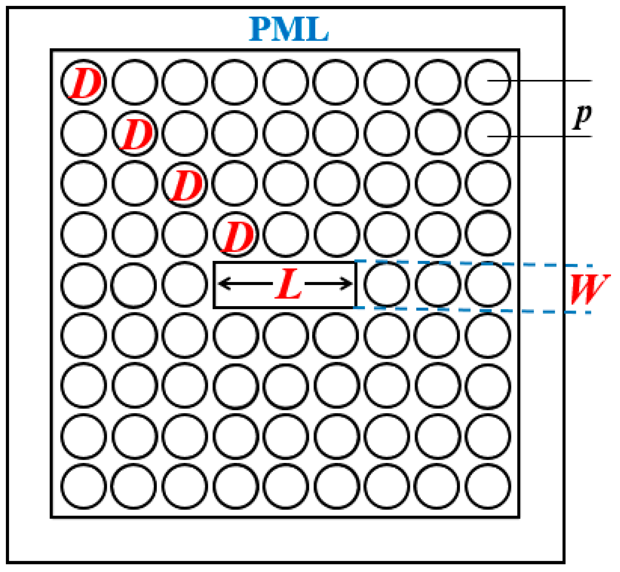
2. Design of the Proposed Sensor

The proposed hollow-core PCF contains a single rectangular shaped air-hole in the center of its structure as shown in Figure 1. The length (L) is three times larger than the width (W) to increase the asymmetry of the structure, thus the hollow-core PCFs provide high birefringence like polarization maintaining (PM) fiber and these can be used in polarization maintaining applications. The cladding region of the proposed structure was designed using an array of circular holes. The diameter of each air hole in the cladding region is denoted as D, and the distance between two adjacent holes is denoted as p. To guarantee a flat dispersion and a good radiation confinement factor, the air-filling fraction (AFF) is kept fixed at 0.95 throughout all numerical analysis. To ease of fabrication, all design parameters (D = W = L/3) in the core and the cladding relate to p as it is difficult to maintain different parameters at the same time during fabrication. The host material of the whole proposed sensor is Zeonex due that this polymer offers several advantages in comparison with other commonly used polymers [14,20]. It has an almost constant refractive index of 1.53 in the study range and its bulk material loss is 0.2 cm−1 in that spectrum also [14,20]. Likewise, Zeonex material is high temperature-insensitive, it has a high chemical resistivity and it is highly biocompatible, which is desirable in sensing applications. On the other hand, the refractive index of the petrol oil changes as a function of the variation of adulteration level. In this case, the RI of petrol depends on the kerosene concentration. Table 1 shows the refractive index of adulterated petrol for several kerosene oil mixtures at room temperature [45]. Likewise, the material attenuation for pure kerosene and pure gasoline was previously reported by Ikeda et al. [46]. As demonstrated in that study, the absorption of these liquids is very low in the THz region, especially for kerosene due to its main component is paraffin, while pure gasoline has appreciable quantities of aromatic hydrocarbons, thus the absorption coefficient of pure gasoline is between 0.87 and 1.48 at 35 cm−1 [46].
Numerical analysis of the proposed petrol adulteration sensor is based on a rectangular shaped hollow-core PCF was performed using COMSOL Multiphysics 5.1. This commercial software makes the numerical analysis using full-vectorial finite element method (FEM). In addition, a rectangular perfectly matched layer (PML) boundary condition was introduced just at the outside of the cladding to absorb the electromagnetic signals propagating towards the core [37,47]. The PML is the most efficient absorption boundary condition, which helps to improve the numerical analysis and avoid possible sources of error [47,48]. The thickness of the PML is an important parameter due to its great impact on the simulation results. Therefore, we carry out the convergence test and found that proposed sensor provides the optimal results at a PML thickness above 10% of the total size of the sensor structure [37,49].
The electric field distribution of the proposed waveguide is evaluated using the FEM to demonstrate that the core is the best place to fill with the sample under test (SUT). In this case, the simulation results were obtained with a D = 93.33, W = 93.33, L = 280, and p = 98.25 µm while the core is filled with pure petrol and kerosene. Figure 2a,b show the electric field distribution for the fundamental mode for x- and y-polarization, respectively, when the proposed sensor is filled with petrol. The electric field distribution for kerosene is shown in Figure 2c,d for both polarization modes. The obtained results show that in the proposed structure the radiation is well confined into the core, for this reason, this region is more sensitive to any changes of the SUT. Likewise, the analysis allowed us to corroborate that the proposed waveguide is a single mode up to 2.8 THz.

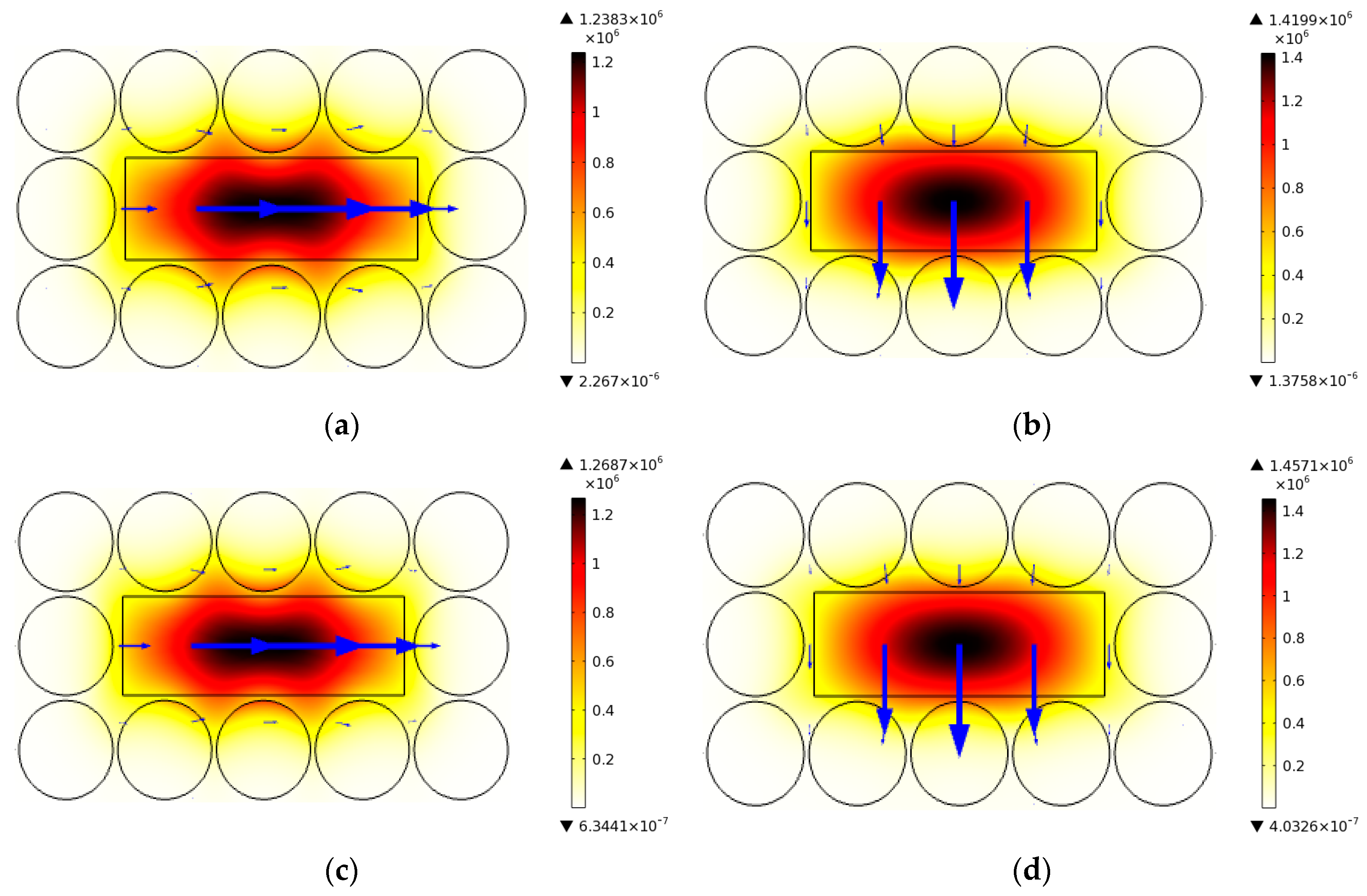
3. Operating Principle

The sensitivity of the petrol adulteration sensor depends on the intensity of radiation-matter interaction (the Beer–Lambert law). The proposed sensor uses this operating principle; thus, it makes the measurements based on the changes in the absorption coefficient at a specific frequency as can be seen from Equation (1). This physical principle is defined as:
I f   =   I 0 f e r α m l c
where I(f) is the intensity of the radiation when the THz waveguide is filled with the SUT, I0(f) is the intensity without the presence of SUT, r is the relative sensitivity of the sensor, αm is the absorption coefficient, lc is the THz-waveguide length filled with the SUT and f the operating frequency. The relative sensitivity is a key parameter because it indicates the capability of the sensor to detect changes in the SUT. The relative sensitivity of this kind of sensor can be determined from the expression in Equation (2) [20]:
r   =   n r n e f f χ
where, nr and neff are the real part of RI of the analyte targeted to be sensed and the effective RI of the guided mode respectively. Note that the effective RI of the guided mode is a term that is very sensitive to changes in the SUT characteristic. In addition, the amount of radiation signal that interacts with the testing analytes is denoted by χ   power   fraction , thus, it is possible to quantify in an easy way how much power travels through the central region to interact with the SUT. The power fraction can be easily calculated using Equation (3) [20]:
χ   =   s a m p l e R e E x H y E y H x d x d y t o t a l R e E x H y E y H x d x d y × 100
where, E and H represent the electric field and magnetic field of the propagating signal respectively. The subscript x and y indicate the polarization towards x- and y-axis. In (3), the denominator performs the integration of real part (Re) of the total power over the total fiber dimension and the numerator performs the same operation for only the portion of the fiber where the sample exists, i.e., in the core region.

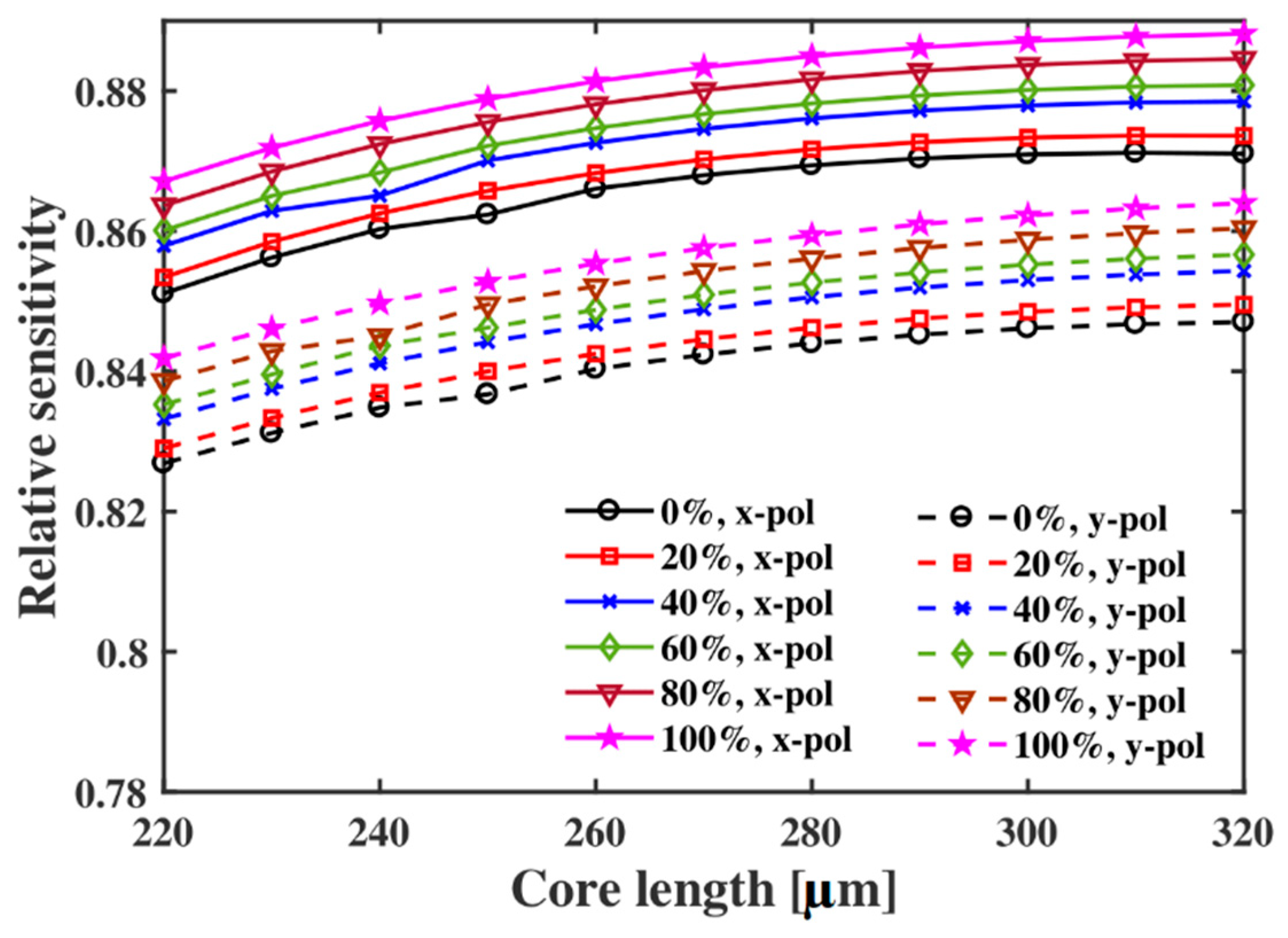
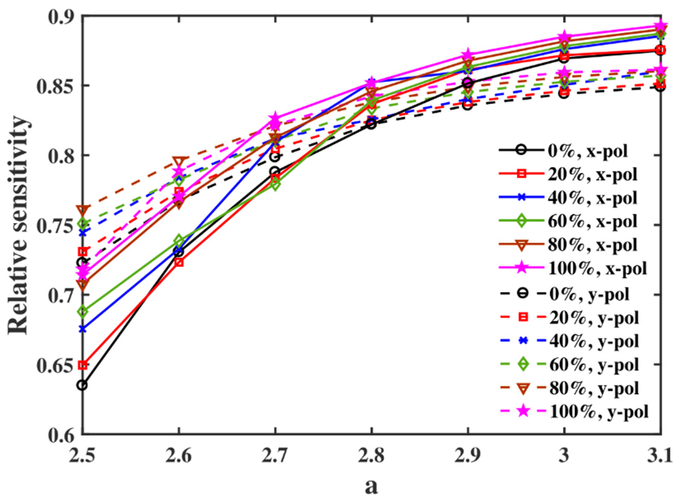
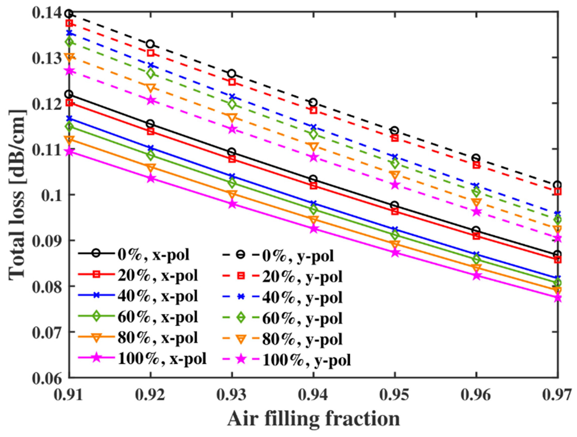
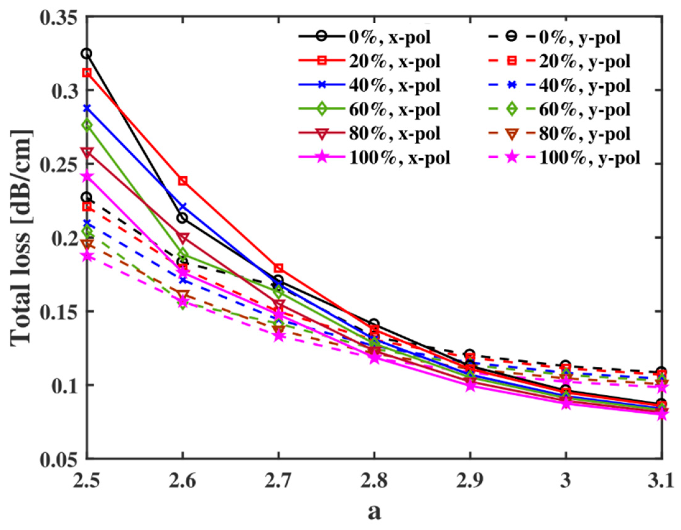
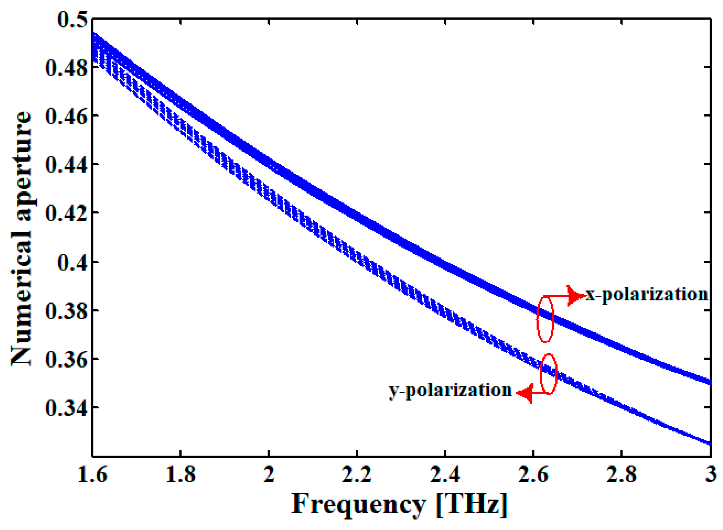
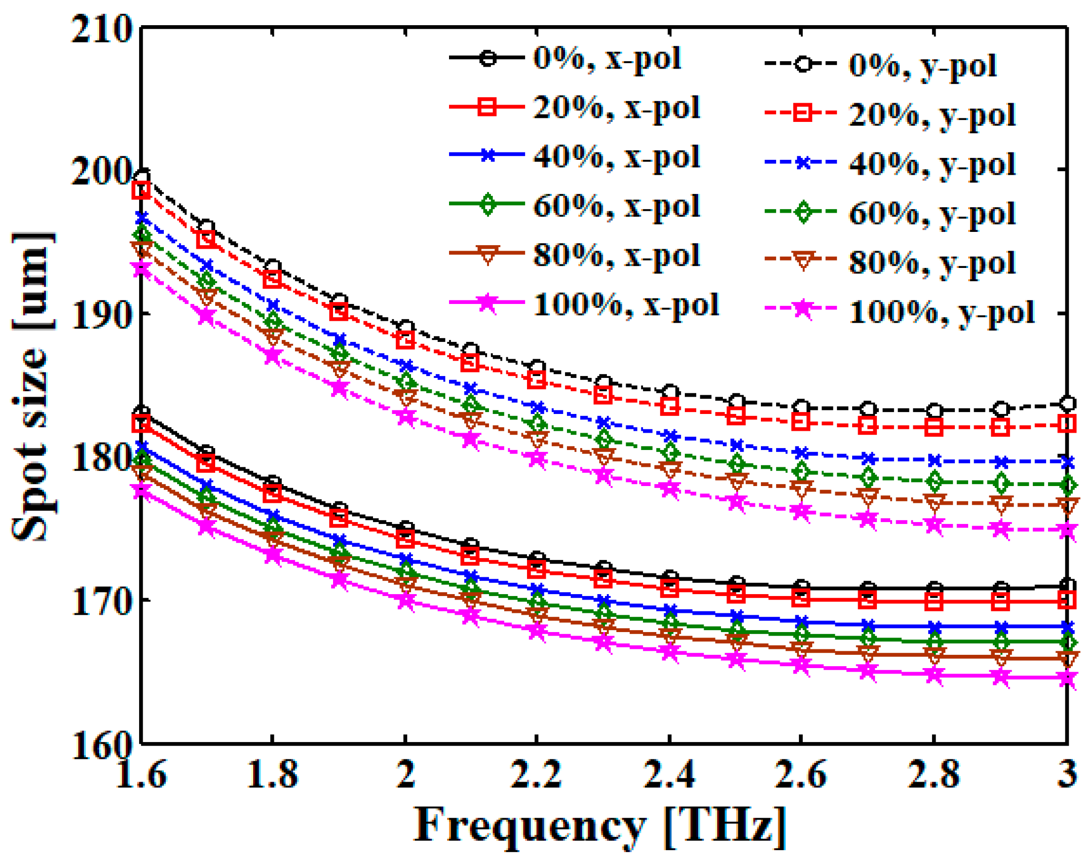
4. Simulation Results and Discussions

The performance of the proposed petrol adulteration sensor is analyzed as a function of the geometry of the THz structure, the air filling fraction, the frequency, and polarization. Firstly, the relative sensitivity of the sensor is evaluated as a function of the length of the rectangular core, where the length is varied from 220 to 320 μm. The analysis is carried out with the frequency fixed at 2.8 THz, while the kerosene concentration (Refractive index of SUT) is changed from 0% to 100%. Figure 3 indicates that the relative sensitivity increases very slowly with the increase of core length. The reason behind this is that the amount of sensing analyte inside the core rises with the rise of the core dimension, thus more radiation interacts with the analyte which increases the relative sensitivity of the proposed sensor device. In addition, Figure 3 indicates that the sensitivity is almost constant after L = 280 µm, so that this core length is considered as the optimum core length. Further increase of the sensor dimension will not increase the sensing capability too much, but the sensor will be bulkiest. Now the characteristics of the proposed hollow-core sensor at the different core length conditions with fixed core width and p is shown in Figure 4 as a function of a (a = L/W). Figure 4 indicates that the relative sensitivity increases with the increase of a. This happens because the lower value of a restricts a fraction of the radiation signal to propagate through the core due to lower length. This occurs because the interaction between radiation and analyte is less and the relative sensitivity decreases. On the other hand, a higher core length-width ratio permits more radiation to travel within the core, which helps to increase the sensitivity of the proposed sensor. However, in the proposed sensor, the maximum relative sensitivity occurs when a is equal to 3.1, but the optimum condition is considered as a = 3. Due that if a is higher than 3.0 the rectangular air hole is very close to the cladding air holes; thus, the fabrication complexity of the proposed structure increases significantly. For the above, L = 3 × W is considered as the optimal ratio between the core dimensions in our case. After that, the variation of relative sensitivity of this hollow-core sensor is investigated at different AFF. The obtained results are summarized in Figure 5. The results reveal that the relative sensitivity rises when AFF increases. A high AFF permits low solid material at the cladding and the refractive index difference between core and cladding increases, so more radiation opts to propagate through the core. This phenomenon increases the relative sensitivity with the increase of AFF. According to Figure 5, this proposed fiber will offer maximum relative sensitivity when AFF = 0.97 but to reduce fabrication complexity optimum AFF is selected as 0.95. This AFF provide high relative sensitivity as well as enough space between two adjacent air holes. Finally, the characteristics of relative sensitivity of the reported oil adulteration sensor for different operating frequencies are reported in Figure 6, while the length of the rectangular core remains constant at L = 280 µm. These results show that the relative sensitivity increases rapidly from 1.6 to 2.8 THz, and after that, it remains constant. The electromagnetic signals at high frequencies tend to travel across the higher refractive indexed area so that more radiation propagates through the higher refractive indexed oil instead of lower refractive indexed air at higher f. That’s why the relative sensitivity increases at higher operating frequencies. When the operating signal frequency is 2.8 THz or higher, the amount of radiation inside the core will be saturated which in turn keep the relative sensitivity unchanged. The reported relative sensitivity of the proposed sensor with a core length of 280 µm and operating frequency 2.8 THz is shown in Table 2.
It is evident from Figure 1 that the proposed sensor presents high asymmetry due to the asymmetrical structure along the horizontal and vertical axis. When travels through the z-direction, the THz radiation will be polarized along the x and y-axis. Then, the birefringent exists when the refractive index in both directions are not equal. Birefringence is the absolute difference between the effective refractive index in x and y direction and it can be obtained using Equation (4) [14,49]:
B = n x n y
where nx and ny represents the actual refractive index of core in x and y directions when the radiation propagates through the z-direction. This property is important in sensing application due that the waveguide can split the maximum amount of power in one specific direction (either x or y) so that the received signal can be analyzed more accurately with lower-powered incident THz radiation. As birefringence is dependent on the asymmetry of the core so the variation of birefringence at different core length (L variable, W fixed) is reported in Figure 7. This figure indicates that the birefringence rises with the increase of core length-to-width ratio because the increased a ensures higher asymmetry and the birefringence increases. The birefringence of the proposed sensor as a function of the length of the device is shown in Figure 8, while the frequency remains fixed at 2.8 THz. From the numerical results, the birefringence decreases when the length of the core increases. The birefringence is higher for smaller core lengths due to a larger part of the evanescent field interacts with the cladding, which induces an extra asymmetry for the presence of the circular holes of cladding region. On the other hand, the radiation is well confined into the core for larger core length, thus the THz radiation only is propagated into the central zone, and the difference between the refractive index of two directions decreases, which slows down the birefringence. Once more, the relationship between the birefringence and the operating radiation signal frequency at a fixed core dimension is reported in Figure 9. The obtained results show that the birefringence decreases with the frequency. In fact, the birefringence is lower at higher frequencies owing to the wavelength of the wave is smaller and therefore the radiation is well confined into the core of the proposed structure. In the other sense, at lower frequencies the wavelength of the wave is larger, and radiation can interact with the cladding region, which adds an extra birefringence factor. Thus, at f = 2.8 THz and L = 280 µm the birefringence is 6.9 × 10⁻³ for all percentages of adulterated fuel.
At the time of propagating electromagnetic signals through the optical waveguide, two types of losses must exist inside the fiber which is known as confinement loss and bulk material loss. The first one is due to the absorption of radiation by the air present in the cladding and the second one exists due to the presence of background material in the core. The confinement loss of any kind of optical waveguide can be quantified by using the following expression [14]:
α C L   =   8.686 2 π f c I m   n e f f   dB / cm
where, the operating terahertz signal frequency is expressed by f, Im(neff) stands for the imaginary part of the effective refractive index and c is the velocity of light in free space. The confinement loss of the proposed fiber as a function of the frequency is shown in Figure 10. As stated earlier, the radiation always tries to travel through the higher refractive index area so that the amount of radiation in the cladding decreases at higher operating frequencies, which reduces the confinement losses. Again, at a fixed frequency, the refractive index increases due to the adulteration level of kerosene, so the confinement loss also decreases. At optimum core length condition, the confinement losses are very low, and it is around 10 8 dB/m for both x- and y-polarization modes. Now, effective material loss (EML) or bulk material loss is investigated. A fraction of the radiated signal is trapped in the material of the core, which is responsible for this type of loss. This loss can be calculated by using the following mathematical expression [14,49]:
α e f f = ε 0 μ 0 1 2 A m a t n α m a t Ε 2 d A 2 A l l S z d A cm 1
where, the permittivity and permeability in free space are symbolized by ε 0 and μ 0 respectively. The effective refractive index of the light is expressed as n and the bulk material coefficient is represented by αmat. In (6), the electric field intensity is expressed as E, Sz stands for the pointing vector in the z-direction and A represents the area over which the integration will be performed. The above expression is the ratio of energy captured by the material present in the path of radiation propagation and the total radiation energy inside the fiber. The graphical representation of EML at a fixed core length condition of the proposed THz waveguide is shown in Figure 11. There, the EML is analyzed as a function of the operating frequency. The reported figure indicates that the EML decreases with the increase of operating signal frequency from 1.6 to 2.6 THz and after that, the EML is almost constant. At 2.8 THz the EML is 0.022–0.025 cm−1 and 0.026–0.029 cm−1 for x- and y-polarization mode respectively at different adulteration level when L = 280 µm.
Now, the total loss (confinement loss + EML) characteristics of the proposed HC-PCF is analyzed for different frequencies, air filling fraction, and core length. The graphical representation of total loss for different operating frequencies is shown in Figure 12 for the optimum designing conditions. This loss decreases with the increase in operating frequency as both losses show the same characteristics. At 2.8 THz, the proposed fiber offers very low loss (less than 0.1 dB/cm) which enriches its guiding properties. Moreover, the variation of total loss as a function of AFF is reported in Figure 13 for L = 280 µm, which reveals that the loss is lower for higher AFF. For higher AFF the solid material is reduced so the loss is lower for all percentages of adulterated fuel. After that, the relationship between the total loss and a is shown in Figure 14 which indicates that the loss is higher for lower a and reduces with the increase of a. At optimum geometric conditions, the proposed sensor offers very low loss which highlights the sensor’s superiority.
Likewise, the numerical aperture of the proposed sensor is investigated. This parameter is the measure of the angular acceptance of incoming radiation for an optical system which is dependent on the geometric structure of the waveguide. The numerical aperture of an optical fiber-based system can be calculated by using the following expression [40]:
N A = 1 1 + π A e f f f 2 c 2
where, Aeff is the effective area which indicates the real area through which the total radiation propagates, and f is the frequency of the terahertz signal. A high NA is desirable in this kind of sensors due that more radiation travels through the waveguide. The relationship between the NA and operating radiation signal frequency is shown in Figure 15. The reported figure indicates that NA decreases when the operating frequency increases owing to the radiation is tightly confined at higher frequencies and the effective area decreases. At optimum core length, the numerical apertures are 0.36 and 0.34 for x and y-polarization mode at 2.8 THz.
Another important parameter to analyze is the spot size of the proposed oil adulteration sensor. For sensing application, it is desirable to have a large spot size in order to increase the interaction between the radiation and the sample under test. The spot size can be calculated by using the following expression [43,50]:
W e f f = R × ( 0.65 + 1.619 × V 1.5 + 2.879 × V 6 )
where, R is the radio of the hollow core and V is the value of normalized frequency parameter [50]. The graphical representation of the spot size of that proposed sensor is shown in Figure 16 as a function of frequency. The obtained results show that the spot size decreases with the increase of operating signal frequency due to the more confinement of radiation in a small area until 2.8 THz and after that, the spot size is almost constant. At optimum core length condition, the average spot size is 170 µm for all concentrations of kerosene when the operating frequency is 2.8 THz. From the obtained results, we can conclude that the proposed structure presents a great potential to be used as petrol adulteration sensor.
Finally, the possible fabrication methodology is proposed to make the sensor in real life. In the last decade, many technological breakthroughs in manufacturing techniques of optical fibers specifically PCFs have been developed around the world, which help to fabricate complex structures such as slotted air-holes and circular air-holes with high precision and accuracy [51,52,53]. From the above, we believe that the proposed structure could be manufactured using two different techniques as it presents different structures in cladding and core regions. Then, the best approach to construct the cladding region is the technique based on the stack and draw due that it has demonstrated to be a precise method for efficient construction of a PCF with circular holes [3,54]. On the other hand, the extrusion technique could be used to obtain the rectangular core because this method has already proven to be very accurate in this type of geometries. Actually, some recent works provide experimental evidence of the fabrication of THz waveguides with rectangular holes [52,55,56].

5. Conclusions

A petrol adulteration sensor in the THz band based on hollow-core photonic crystal fiber (PCF) was proposed and numerically analyzed. To investigate the performance of the proposed sensor configuration, the finite element method was employed. Thus, we demonstrated that the proposed petrol adulteration sensor achieves extremely high relative sensitivity of 89%, and ultra-low confinement loss of 10−8 dB/cm at 2.8 THz when it is employed to characterize kerosene samples at different concentrations. Besides, other characteristics of the proposed THz waveguide were analyzed and evidenced that this configuration presents high birefringence, low effective material loss, large effective modal area, and high numerical aperture, which make it suitable to be used in real applications. Likewise, the proposed sensor has a simple structure which makes viable its fabrication with the current manufacturing technology. Then, the proposed alternative could be interesting in the petrol industry because it could be used to detect and quantify the adulteration of petrol derivatives when petrol is mixed with other solvents like alcohol or similar substances.

Author Contributions

All the authors contributed extensively to the work presented in this document. E.R.-V. made an important contribution to this article regarding analysis, design of methodology, funding acquisition and writing of the manuscript; M.A.H. designed the sensor, designed the methodology, analyzed the data writing of the manuscript, and contributed to the acquisition of data; J.V.-A. helped with the conceptualized of the proposed sensor and made a rigorous revision of the literature to state the main differences with other similar works; M.S.A. participated in the critical review of the article for important intellectual content and oversaw the entire study; in addition, he helped with the resources, formal analysis, data curation and project administration. All the authors performed the analysis and interpretation of the data. All authors have read and agreed to the published version of the manuscript.

Funding

The authors thank the Instituto Tecnológico Metropolitano for funding this work through project P17217. In addition, the authors thank the Instituto Tecnologico Metrpolitano for paying the APC.

Conflicts of Interest

The authors declare no conflict of interest.

References

  1. Knight, J.C.; Birks, T.A.; Cregan, R.F.; Russell, P.S.J.; de Sandro, J.-P. Photonic crystals as optical fibres—Physics and applications. Opt. Mater. (Amst.) 1999, 11, 143–151. [Google Scholar] [CrossRef]
  2. Knight, J.C.; Arriaga, J.; Birks, T.A.; Ortigosa-Blanch, A.; Wadsworth, W.J.; Russell, P.S.J. Anomalous dispersion in photonic crystal fiber. IEEE Photonics Technol. Lett. 2000, 12, 807–809. [Google Scholar] [CrossRef]
  3. Russell, P.S.J. Photonic-crystal fibers. J. Lightware Technol. 2006, 24, 4729–4749. [Google Scholar] [CrossRef]
  4. Ye, Q.; Xu, C.; Liu, X.; Knox, W.H.; Yan, M.F.; Windeler, R.S.; Eggleton, B. Dispersion Measurement of Tapered Air-Silica Microstructure Fiber by White-Light Interferometry. Appl. Opt. 2002, 41, 4467. [Google Scholar] [CrossRef]
  5. Belardi, W.; Sazio, P.J. Borosilicate Based Hollow-Core Optical Fibers. Fibers 2019, 7, 73. [Google Scholar] [CrossRef] [Green Version]
  6. Thomson, D.; Zilkie, A.; Bowers, J.E. Roadmap of optical communications. J. Opt. 2016, 18, 063002. [Google Scholar] [CrossRef]
  7. Reyes-Vera, E.; Senior, D.E.; Luna-Rivera, J.M.; López-Giraldo, F.E. Advances in electromagnetic applications and communications. TecnoLógicas 2018, 21, 9–13. [Google Scholar] [CrossRef] [Green Version]
  8. Wu, T.L.; Chao, C.H. A novel ultraflattened dispersion photonic crystal fiber. IEEE Photonics Technol. Lett. 2005, 17, 67–69. [Google Scholar] [CrossRef]
  9. Rao, Y.J.; Deng, M.; Duan, D.W.; Zhu, T. In-line fiber Fabry-Perot refractive-index tip sensor based on endlessly photonic crystal fiber. Sens. Actuators A Phys. 2008, 148, 33–38. [Google Scholar] [CrossRef]
  10. Habib, M.A.; Anower, M.S. Square Porous Core Microstructure Fiber for Low Loss Terahertz Applications. Opt. Spectrosc. 2019, 126, 607–613. [Google Scholar] [CrossRef]
  11. Muñoz-Hernández, T.; Reyes-Vera, E.; Torres, P. Tunable Whispering Gallery Mode Photonic Device Based on Microstructured Optical Fiber with Internal Electrodes. Sci. Rep. 2019, 9, 12083. [Google Scholar] [CrossRef] [PubMed]
  12. Montoya Cardona, J.A.; Gomez Cardona, N.D.; Gonzalez Valencia, E.; Torres Trujillo, P.; Reyes Vera, E. Tunable Mode Converter Device Based on Photonic Crystal Fiber with a Thermo-Responsive Liquid Crystal Core. Photonics 2019, 7, 3. [Google Scholar] [CrossRef] [Green Version]
  13. Wong, W.C.; Zhou, W.; Chan, C.C.; Dong, X.; Leong, K.C. Cavity ringdown refractive index sensor using photonic crystal fiber interferometer. Sens. Actuators B Chem. 2012, 161, 108–113. [Google Scholar] [CrossRef]
  14. Habib, M.A.; Reza, M.S.; Abdulrazak, L.F.; Anower, M.S. Extremely high birefringent and low loss microstructure optical waveguide: Design and analysis. Opt. Commun. 2019, 446, 93–99. [Google Scholar] [CrossRef]
  15. Hao, H.; Wang, D.; Wang, Z. Design of Substrate-Integrated Waveguide Loading Multiple Complementary Open Resonant Rings (CSRRs) for Dielectric Constant Measurement. Sensors 2020, 20, 857. [Google Scholar] [CrossRef] [Green Version]
  16. Gomez-Cardona, N.; Reyes-Vera, E.; Torres, P. High Sensitivity Refractive Index Sensor Based on the Excitation of Long-Range Surface Plasmon Polaritons in H-Shaped Optical Fiber. Sensors 2020, 20, 2111. [Google Scholar] [CrossRef] [PubMed] [Green Version]
  17. Gomez-Cardona, N.D.; Reyes-Vera, E.; Torres, P.I. Multi-Plasmon Resonances in Microstructured Optical Fibers: Extending the Detection Range of SPR Sensors and a Multi-Analyte Sensing Technique. IEEE Sens. J. 2018, 18, 7492–7498. [Google Scholar] [CrossRef]
  18. Islam, M.S.; Cordeiro, C.M.B.; Sultana, J.; Aoni, R.A.; Feng, S.; Ahmed, R.; Dorraki, M.; Dinovitser, A.; Ng, B.W.H.; Abbott, D. A Hi-Bi Ultra-Sensitive Surface Plasmon Resonance Fiber Sensor. IEEE Access 2019, 7, 79085–79094. [Google Scholar] [CrossRef]
  19. Habib, A. Ultra low loss and dispersion flattened microstructure fiber for terahertz applications. Brill. Eng. 2020, 1, 1–5. [Google Scholar] [CrossRef]
  20. Reza, M.S.; Habib, M.A. Extremely sensitive chemical sensor for terahertz regime based on a hollow-core photonic crystal fibre. Ukr. J. Phys. Opt. 2020, 21, 8–14. [Google Scholar] [CrossRef] [Green Version]
  21. Barh, A.; Pal, B.P.; Agrawal, G.P.; Varshney, R.K.; Rahman, B.M.A. Specialty Fibers for Terahertz Generation and Transmission: A Review. IEEE J. Sel. Top. Quantum Electron. 2016, 22, 365–379. [Google Scholar] [CrossRef] [Green Version]
  22. Habib, M.A.; Anower, M.S. Low loss highly birefringent porous core fiber for single mode terahertz wave guidance. Curr. Opt. Photonics 2018, 2, 215–220. [Google Scholar] [CrossRef]
  23. Beresna, M.; Gecevičius, M.; Kazansky, P.G. Ultrafast laser direct writing and nanostructuring in transparent materials. Adv. Opt. Photonics 2014, 6, 293. [Google Scholar] [CrossRef]
  24. Wang, K.; Mittleman, D.M. Metal wires for terahertz wave guiding. Nature 2004, 432, 376–379. [Google Scholar] [CrossRef]
  25. Lai, C.-H.; Hsueh, Y.-C.; Chen, H.-W.; Huang, Y.; Chang, H.; Sun, C.-K. Low-index terahertz pipe waveguides. Opt. Lett. 2009, 34, 3457–3459. [Google Scholar] [CrossRef] [PubMed]
  26. Islam, M.S.; Sultana, J.; Rifat, A.A.; Dinovitser, A.; Wai-Him Ng, B.; Abbott, D. Terahertz sensing in a hollow core photonic crystal fiber. IEEE Sens. J. 2018, 18, 4073–4080. [Google Scholar] [CrossRef]
  27. Reyes Vera, E.E.; Usuga Restrepo, J.; Botero Cadavid, J.; Zuñiga, J. Design of low loss photonic crystal fiber based on porous-core with elliptical holes in THz regime. In Proceedings of the Third International Conference on Applications of Optics and Photonics, Faro, Portugal, 8–12 May 2017; Martins Costa, M.F.P., Ed.; SPIE: Bellingham, WA, USA, 2017; p. 237. [Google Scholar]
  28. Islam, M.S.; Cordeiro, C.M.B.; Franco, M.A.R.; Sultana, J.; Cruz, A.L.S.; Abbott, D. Terahertz optical fibers [Invited]. Opt. Express 2020, 28, 16089. [Google Scholar] [CrossRef]
  29. Sultana, J.; Islam, M.S.; Cordeiro, C.M.B.; Dinovitser, A.; Kaushik, M.; Ng, B.W.-H.; Abbott, D. Terahertz Hollow Core Antiresonant Fiber with Metamaterial Cladding. Fibers 2020, 8, 14. [Google Scholar] [CrossRef] [Green Version]
  30. Biplob Hossain, M.; Riazul Islam, S.M.; Tasrif Hossain, K.M.; Faisal Abdulrazak, L.; Nazmus Sakib, M.; Amiri, I.S. High sensitivity hollow core circular shaped PCF surface plasmonic biosensor employing silver coat: A numerical design and analysis with external sensing approach. Results Phys. 2020, 16. [Google Scholar] [CrossRef]
  31. Lee, S.H.; Lee, D.; Choi, M.H.; Son, J.H.; Seo, M. Highly Sensitive and Selective Detection of Steroid Hormones Using Terahertz Molecule-Specific Sensors. Anal. Chem. 2019, 91, 6844–6849. [Google Scholar] [CrossRef]
  32. Jepsen, P.U.; Møller, U.; Merbold, H. Investigation of aqueous alcohol and sugar solutions with reflection terahertz time-domain spectroscopy. Opt. Express 2007, 15, 14717. [Google Scholar] [CrossRef] [PubMed]
  33. Hossain, M.B.; Podder, E.; Bulbul, A.A.M.; Mondal, H.S. Bane chemicals detection through photonic crystal fiber in THz regime. Opt. Fiber Technol. 2020, 54. [Google Scholar] [CrossRef]
  34. Idehara, T.; Sabchevski, S.P.; Glyavin, M.; Mitsudo, S. The gyrotrons as promising radiation sources for THz sensing and imaging. Appl. Sci. 2020, 10, 980. [Google Scholar] [CrossRef] [Green Version]
  35. Panda, A.; Puspa Devi, P. Photonic crystal biosensor for refractive index based cancerous cell detection. Opt. Fiber Technol. 2020, 54, 102123. [Google Scholar] [CrossRef]
  36. Bilal, M.M.; Bi, W.; Liu, X.; Yang, L.; Wa, J.; Madni, H.A. Magnetic field sensor based on the magnetic fluid infiltration into the cladding air holes of the solid-core photonic crystal fiber. Opt. Eng. 2019, 58, 1. [Google Scholar] [CrossRef]
  37. Reyes-Vera, E.; Usuga-Restrepo, J.; Jimenez-Durango, C.; Montoya-Cardona, J.; Gomez-Cardona, N. Design of Low-loss and Highly Birefringent Porous-Core Photonic Crystal Fiber and Its Application to Terahertz Polarization Beam Splitter. IEEE Photonics J. 2018, 10, 1–13. [Google Scholar] [CrossRef]
  38. Sultana, J.; Islam, M.S.; Ahmed, K.; Dinovitser, A.; Ng, B.W.-H.; Abbott, D. Terahertz detection of alcohol using a photonic crystal fiber sensor. Appl. Opt. 2018, 57, 2426. [Google Scholar] [CrossRef]
  39. Gomez-Cardona, N.; Espinal Zapata, S.; Montoya-Cardona, J.; Reyes-Vera, E. Low-loss and flat dispersion umbrella-shaped and porous-core photonic crystal fiber for terahertz applications. J. Phys. Conf. Ser. 2020, 1547, 012006. [Google Scholar] [CrossRef]
  40. Habib, M.A.; Anower, M.S.; Abdulrazak, L.F.; Reza, M.S. Hollow core photonic crystal fiber for chemical identification in terahertz regime. Opt. Fiber Technol. 2019, 52, 101933. [Google Scholar] [CrossRef]
  41. Hossain, M.B.; Podder, E. Design and investigation of PCF-based blood components sensor in terahertz regime. Appl. Phys. A Mater. Sci. Process. 2019, 125, 1–8. [Google Scholar] [CrossRef]
  42. Islam, M.R.; Kabir, M.F.; Talha, K.M.A.; Islam, M.S. A novel hollow core terahertz refractometric sensor. Sens. Bio-Sens. Res. 2019, 25, 100295. [Google Scholar] [CrossRef]
  43. Islam, M.S.; Sultana, J.; Ahmed, K.; Islam, M.R.; Dinovitser, A.; Ng, B.W.-H.; Abbott, D. A Novel Approach for Spectroscopic Chemical Identification Using Photonic Crystal Fiber in the Terahertz Regime. IEEE Sens. J. 2018, 18, 575–582. [Google Scholar] [CrossRef]
  44. Knoerzer, T.A.; Hill, E.M.; Davis, T.A.; Iacono, S.T.; Johnson, J.E.; Balaich, G.J. Comparative Analysis of Fuel Composition and Physical Properties of Biodiesel, Diesel, Kerosene, and Jet Fuel. J. Chem. Educ. 2018, 95, 1821–1826. [Google Scholar] [CrossRef]
  45. Patra, D.; Mishra, A.K. Effect of sample geometry on synchronous fluorimetric analysis of petrol, diesel, kerosene and their mixtures at higher concentration. Analyst 2000, 125, 1383–1386. [Google Scholar] [CrossRef]
  46. Ikeda, T.; Matsushita, A.; Tatsuno, M.; Minami, Y.; Yamaguchi, M.; Yamamoto, K.; Tani, M.; Hangyo, M. Investigation of inflammable liquids by terahertz spectroscopy. Appl. Phys. Lett. 2005, 87, 111–114. [Google Scholar] [CrossRef]
  47. Saitoh, K.; Koshiba, M. Numerical modeling of photonic crystal fibers. J. Lightware Technol. 2005, 23, 3580–3590. [Google Scholar] [CrossRef] [Green Version]
  48. Islam, M.S.; Sultana, J.; Dinovitser, A.; Faisal, M.; Islam, M.R.; Ng, B.W.-H.; Abbott, D. Zeonex-based asymmetrical terahertz photonic crystal fiber for multichannel communication and polarization maintaining applications. Appl. Opt. 2018, 57, 666. [Google Scholar] [CrossRef]
  49. Ahasan Habib, M.; Shamim Anower, M.; Rabiul Hasan, M. Highly birefringent and low effective material loss microstructure fiber for THz wave guidance. Opt. Commun. 2018, 423, 140–144. [Google Scholar] [CrossRef]
  50. Miyagi, K.; Namihira, Y. Measurements of mode field diameter and effective area for photonic crystal fibers by far field scanning technique. In Proceedings of the TENCON 2010—IEEE Region 10 Annual International Conference, Fukuoka, Japan, 21–24 November 2010; IEEE: Fukuoka, Japan, 2010; pp. 1622–1624. [Google Scholar]
  51. Atakaramians, S.; Afshar, V.S.; Ebendorff-Heidepriem, H.; Nagel, M.; Fischer, B.M.; Abbott, D.; Monro, T.M. THz porous fibers: Design, fabrication and experimental characterization. Opt. Express 2009, 17, 14053. [Google Scholar] [CrossRef]
  52. Ebendorff-Heidepriem, H.; Monro, T.M. Extrusion of complex preforms for microstructured optical fibers. Opt. Express 2007, 15, 15086. [Google Scholar] [CrossRef] [Green Version]
  53. Dupuis, A.; Mazhorova, A.; Désévédavy, F.; Rozé, M.; Skorobogatiy, M. Spectral characterization of porous dielectric subwavelength THz fibers fabricated using a microstructured molding technique. Opt. Express 2010, 18, 13813. [Google Scholar] [CrossRef] [PubMed]
  54. Vera, E.R.; Restrepo, J.Ú.; Varon, M.; Torres, P. Dual-Core Transversally Chirped Microstructured Optical Fiber for Mode-Converter Device and Sensing Application. In Selected Topics on Optical Fiber Technologies and Applications; Xu, F., Mou, C., Eds.; InTech: Vienna, Austria, 2018; ISBN 978-953-51-3813-6. [Google Scholar]
  55. Mignanelli, M.; Wani, K.; Ballato, J.; Foulger, S.; Brown, P. Polymer microstructured fibers by one-step extrusion. Opt. Express 2007, 15, 6183–6189. [Google Scholar] [CrossRef] [PubMed]
  56. Atakaramians, S.; Afshar, V.S.; Fischer, B.M.; Abbott, D.; Monro, T.M. Porous fibers: A novel approach to low loss THz waveguides. Opt. Express 2008, 16, 8845. [Google Scholar] [CrossRef] [PubMed]
Figure 1. The 2-D cross-sectional view of the proposed hollow core photonic crystal fibers (PCF).
Fibers 08 00063 g001
Figure 2. Electric field distribution of the fundamental mode at 2.8 THz: (a) x-polarization, petrol; (b) y-polarization, petrol; (c) x-polarization, kerosene; (d) y-polarization, kerosene.
Fibers 08 00063 g002
Figure 3. Relative sensitivity of the proposed oil adulteration sensor at different core length condition for both x and y-polarization modes at f = 2.8 THz.
Fibers 08 00063 g003
Figure 4. Relative sensitivity of the proposed sensor as a function of (a) (L/W) at 2.8 THz.
Fibers 08 00063 g004
Figure 5. Relative sensitivity of this oil adulteration sensor at different air filling fraction at 2.8 THz and L = 280 µm.
Fibers 08 00063 g005
Figure 6. Relative sensitivity variation characteristics of the proposed fiber at different operating frequency when L = 280 µm.
Fibers 08 00063 g006
Figure 7. Birefringence of the proposed fiber for different core length to width ratio at f = 2.8 THz for different volume of kerosene with petrol.
Fibers 08 00063 g007
Figure 8. Birefringence of the proposed fiber as a function of core length at f = 2.8 THz for different adulteration of petrol oil with kerosene.
Fibers 08 00063 g008
Figure 9. Relationship between birefringence and operating signal frequency at fixed core length for different percentage of mixture of kerosene oil in petrol.
Fibers 08 00063 g009
Figure 10. Confinement loss of the proposed sensor at optimum core length condition for different operating frequency.
Fibers 08 00063 g010
Figure 11. Effective material loss (EML) of the proposed sensor at L = 280 µm as a function of frequency.
Fibers 08 00063 g011
Figure 12. Total loss of the proposed hollow core sensor for different operating frequencies at optimum structural parameters.
Fibers 08 00063 g012
Figure 13. Variation of total loss of that fiber for different AFF at 2.8 THz and L = 280 µm.
Fibers 08 00063 g013
Figure 14. Total loss as a function of a of the reported oil adulterated sensor at 2.8 THz.
Fibers 08 00063 g014
Figure 15. Numerical aperture of the proposed hollow-core sensor as a function of frequency at L = 280 µm.
Fibers 08 00063 g015
Figure 16. Spot size versus frequency of the proposed oil adulteration sensor at optimum core length.
Fibers 08 00063 g016
Table 1. The refractive index of petrol oil for the presence of different concentration of kerosene oil [45].
Concentration of Kerosene (% v/v)0
(Pure Petrol)
20406080100
(Pure Kerosene)
Refractive index1.4181.4211.4271.431.4351.44
Table 2. Relative sensitivity of the proposed oil adulteration measurement sensor at L = 280 µm and f = 2.8 THz.
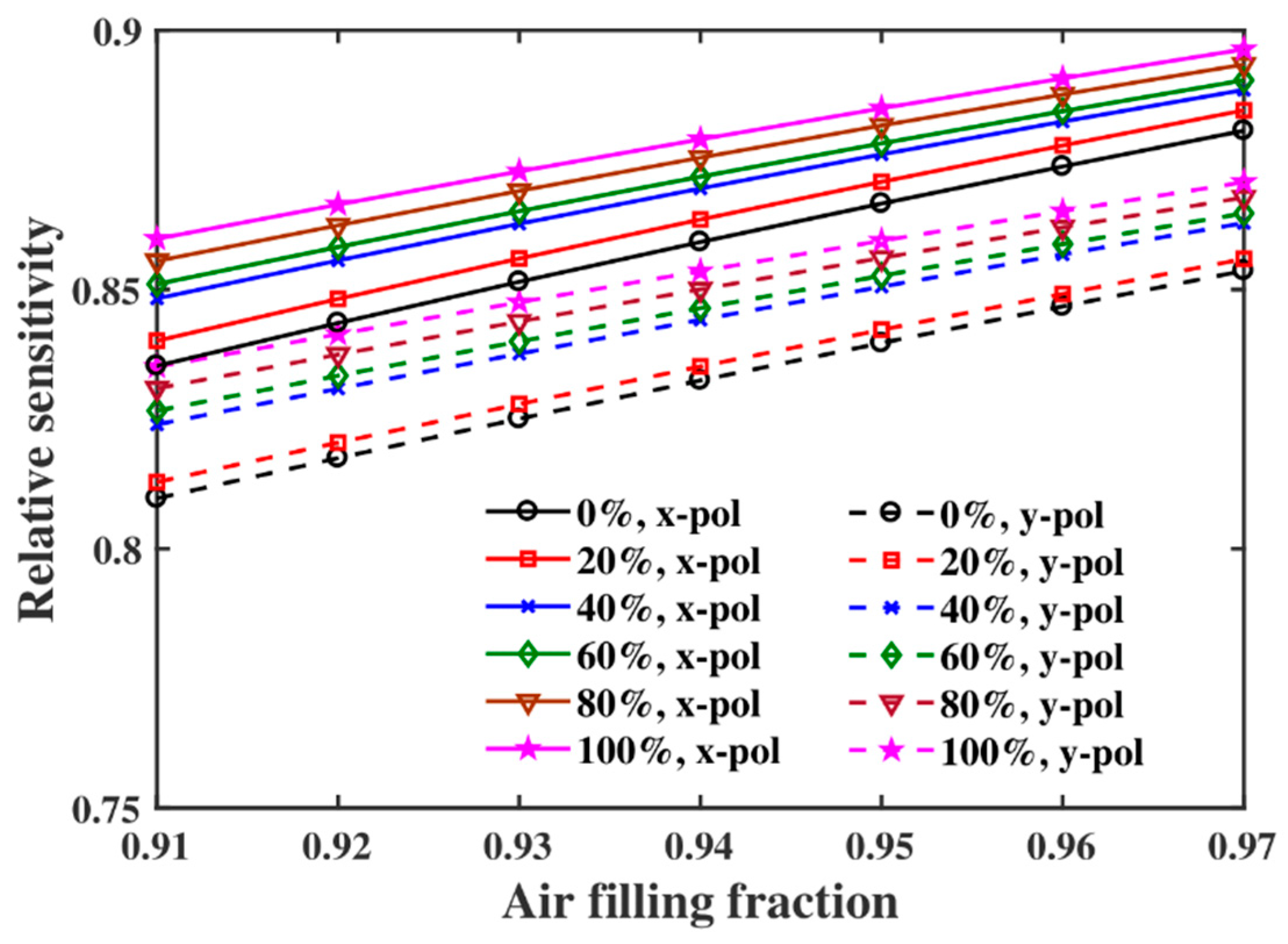
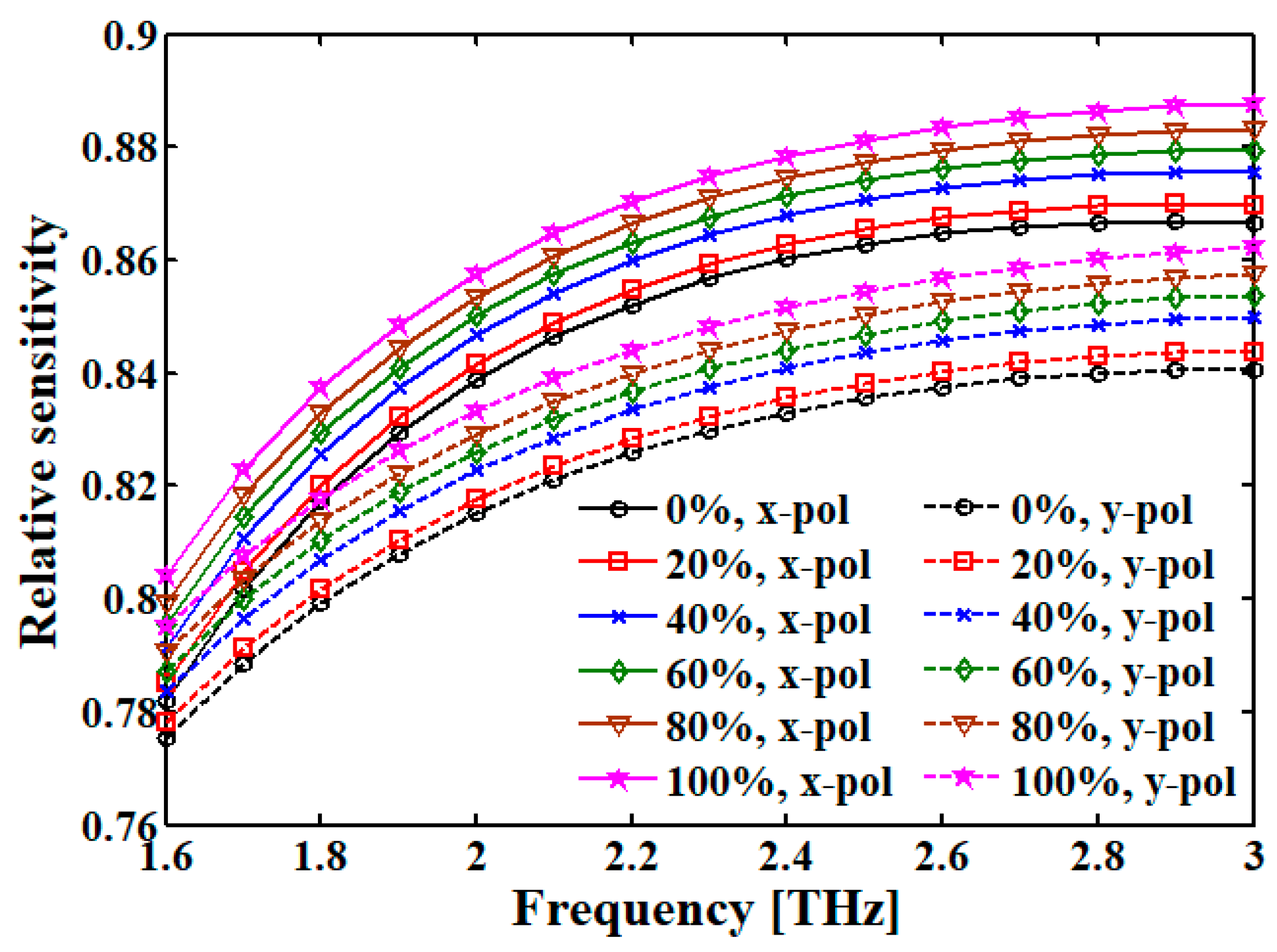
Percentage of Kerosene
(% v/v) in Petrol
Relative Sensitivity
(%) for x-pol
Relative Sensitivity (%)
for y-pol
086.3083.85
2086.9084.30
4087.5084.77
6088.1585.21
8088.8585.67
10089.4086.10

