Experimental Study on the Effectiveness of Inorganic Bonding Materials for Near-Surface Mounting Shear Strengthening of Prestressed Concrete Beams


Abstract
:1. Introduction
2. Research Methodology
3. Experimental Program
3.1. Material Properties
3.1.1. Concrete
3.1.2. Steel Reinforcement and Prestressing Tendons
3.1.3. Carbon FRP Laminates
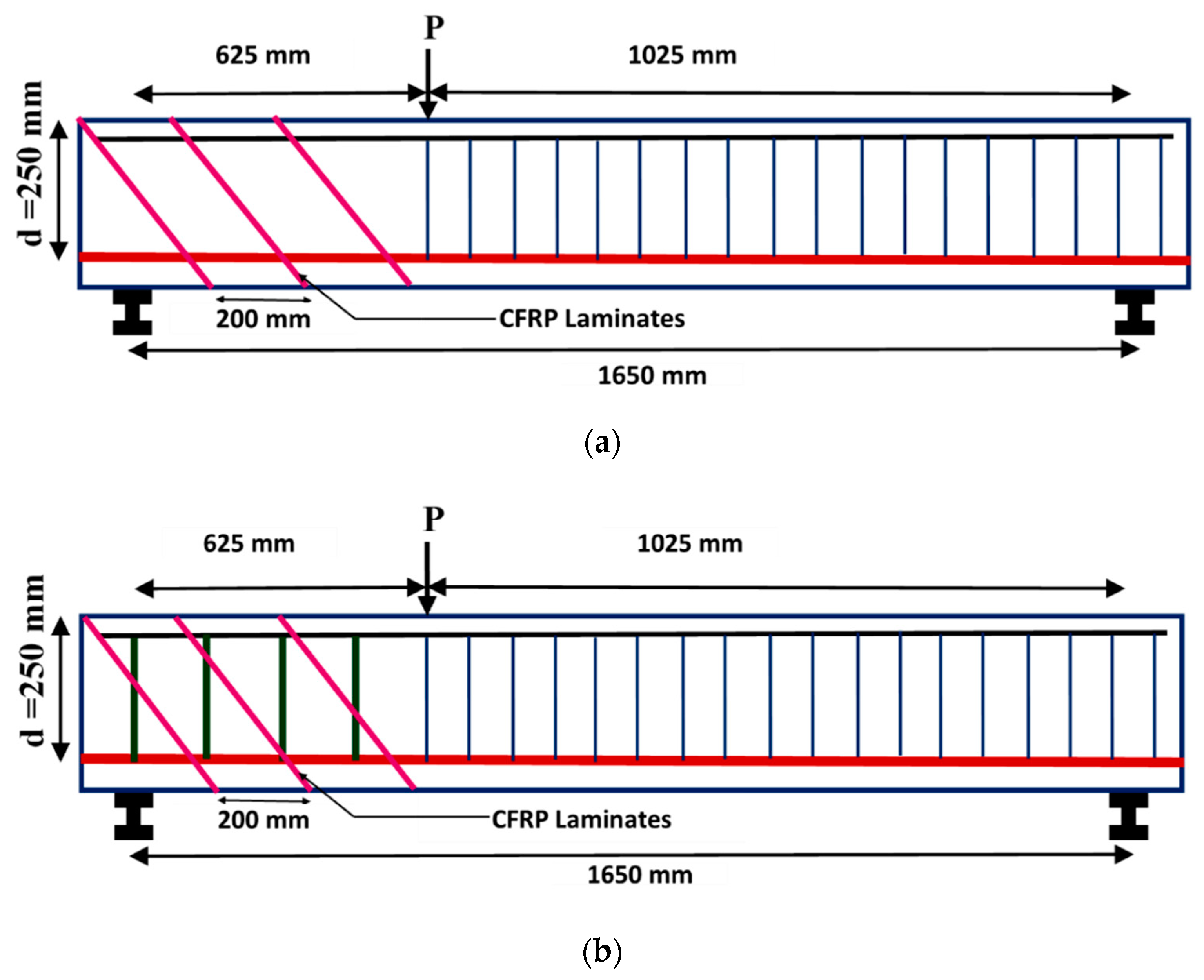
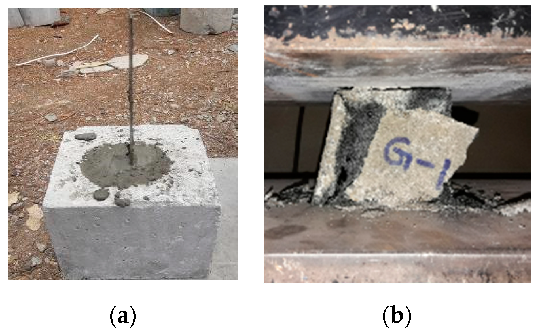
3.2. Pull-Out Tests on Different Bonding Materials
3.2.1. Background
3.2.2. Specimen Preparation
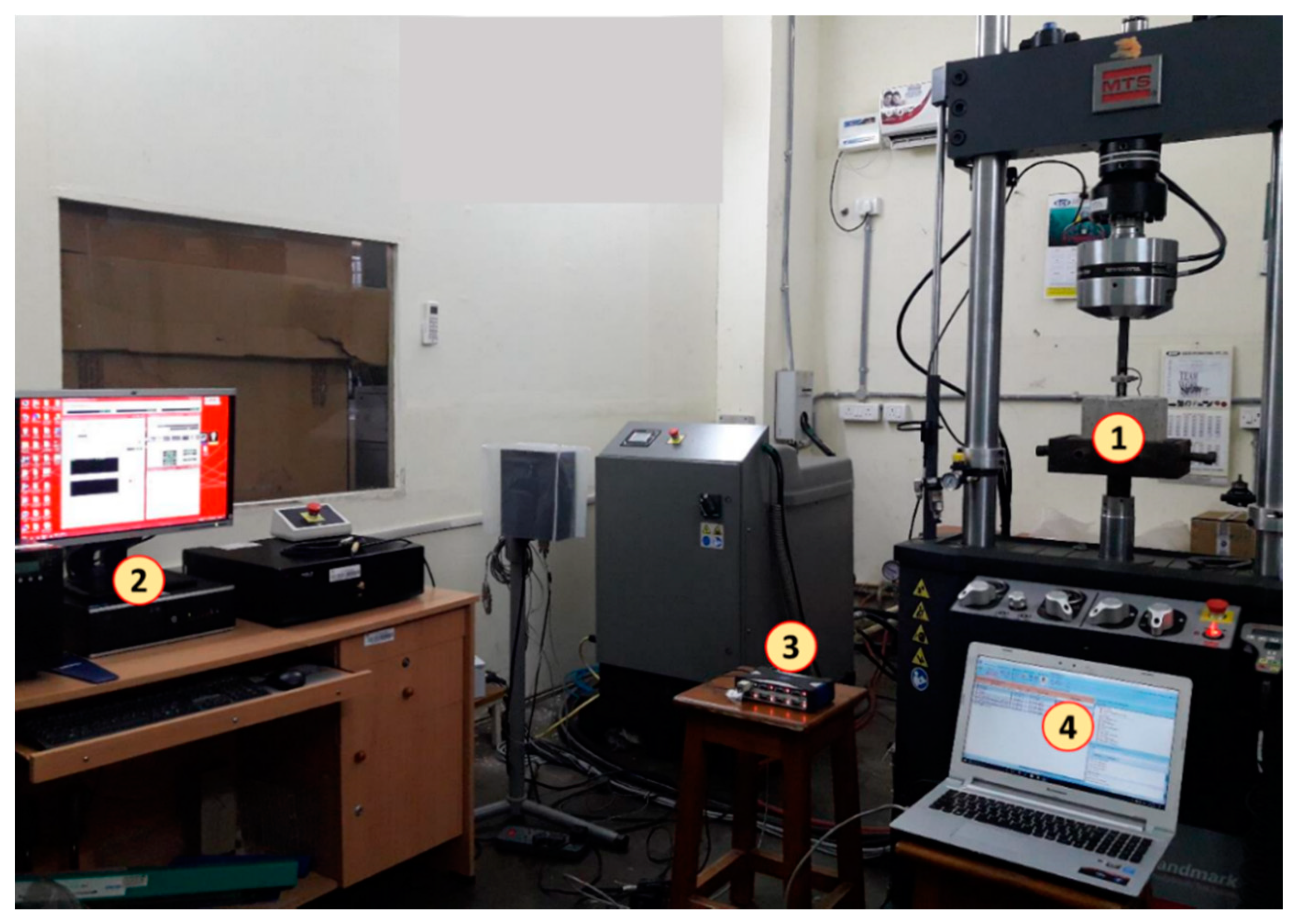
3.2.3. Test Setup and Results
3.2.4. Bond Strength from Analytical Calculations
4. Full Scale Tests on Beams with NSM Shear Strengthening
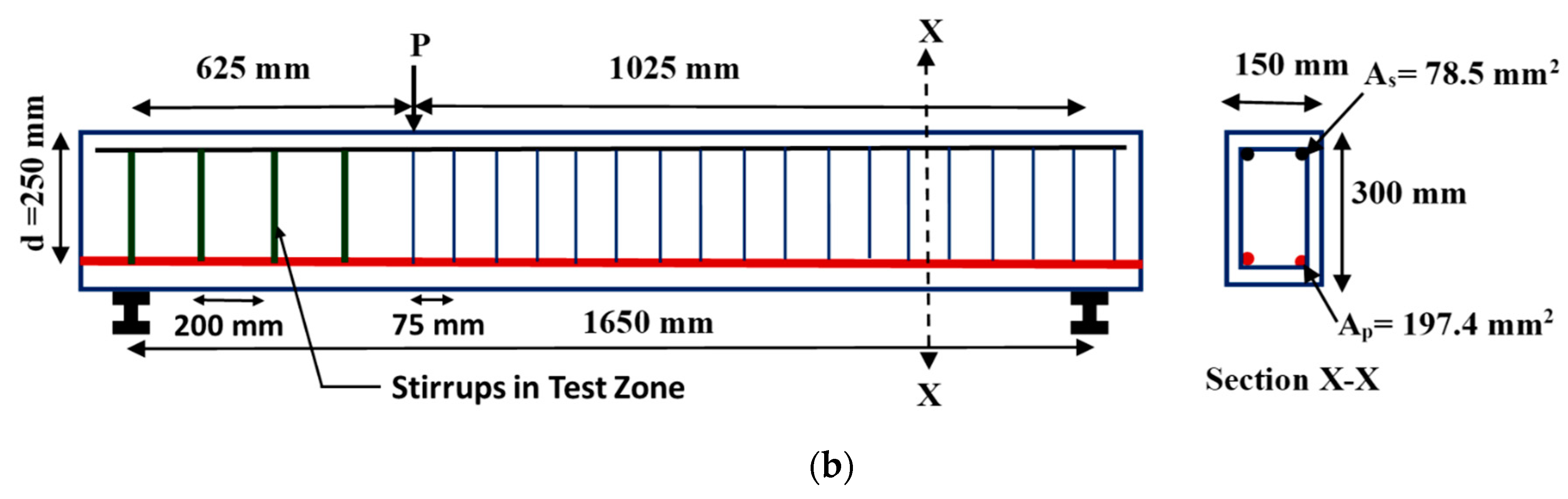
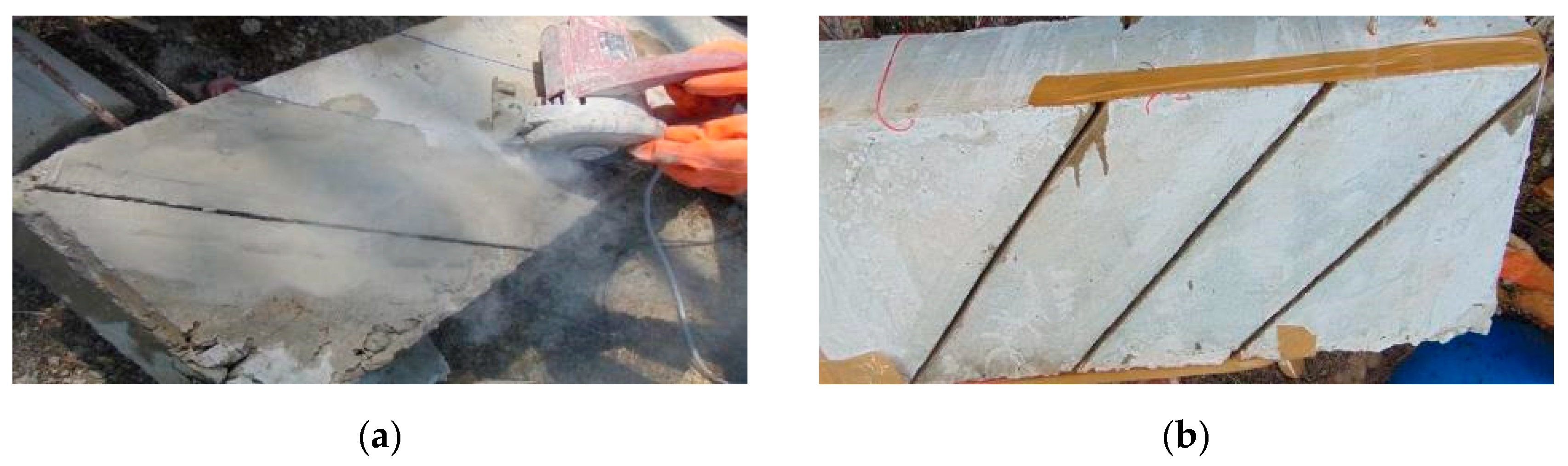
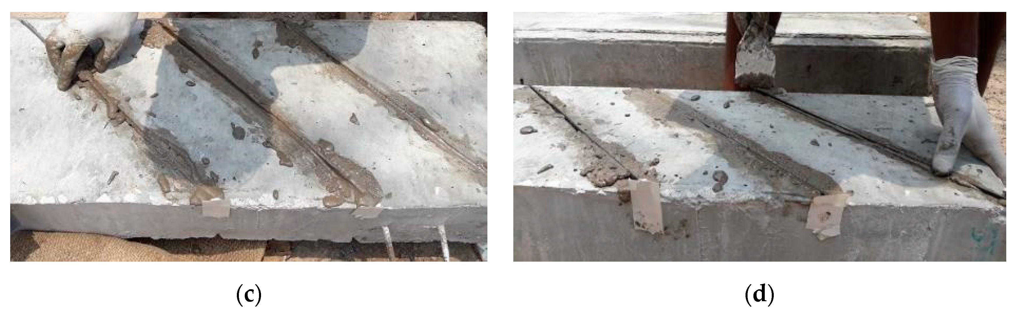
4.1. NSM Shear Strengthening Procedure
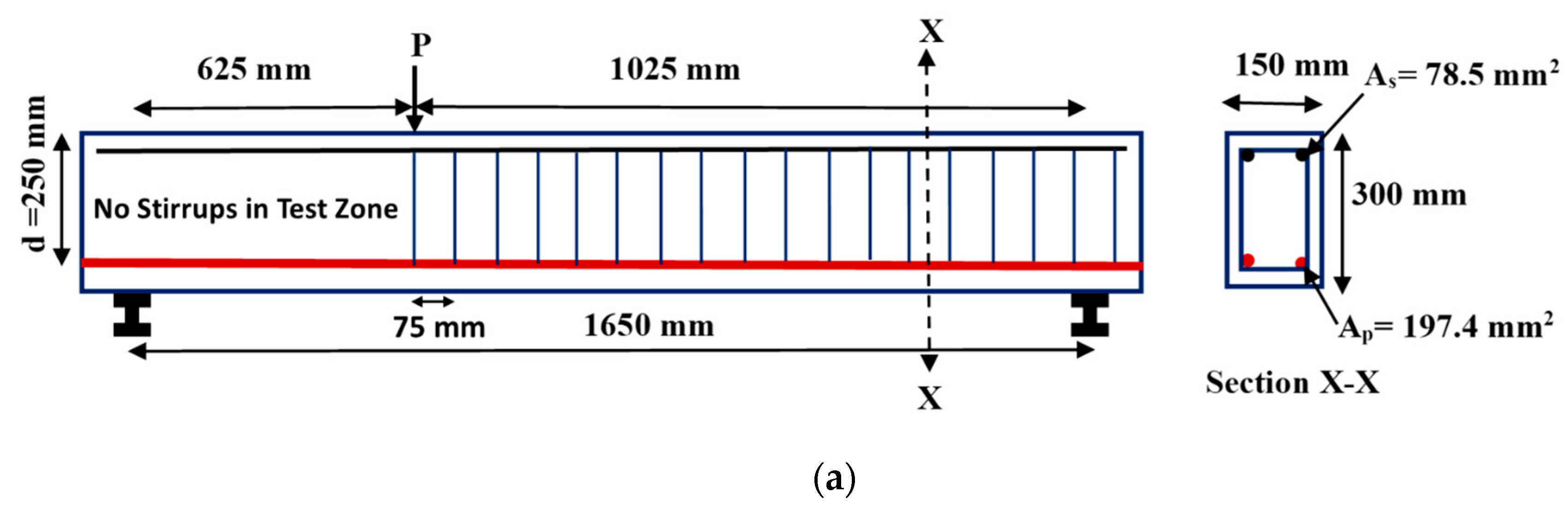
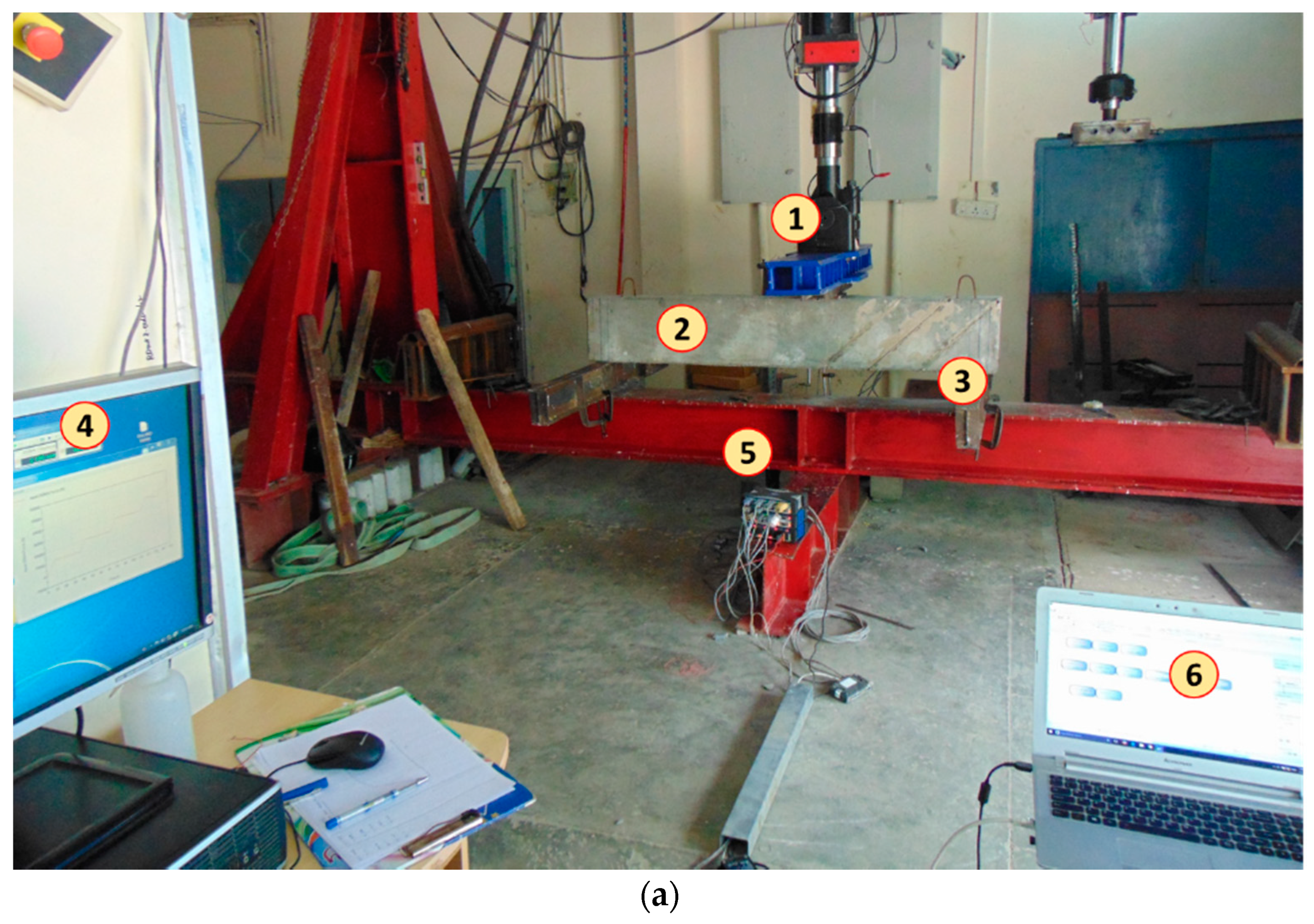
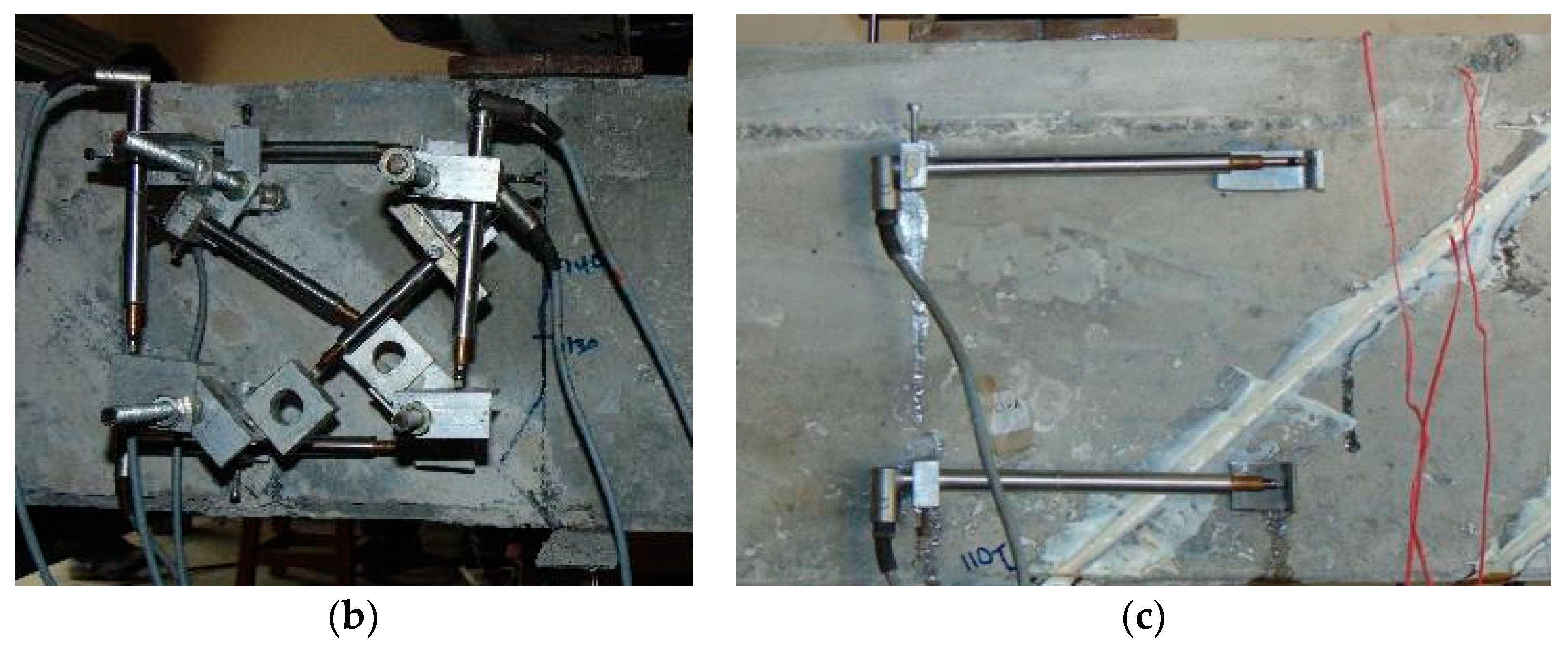
4.2. Test Setup and Instrumentation Details
5. Results and Discussion
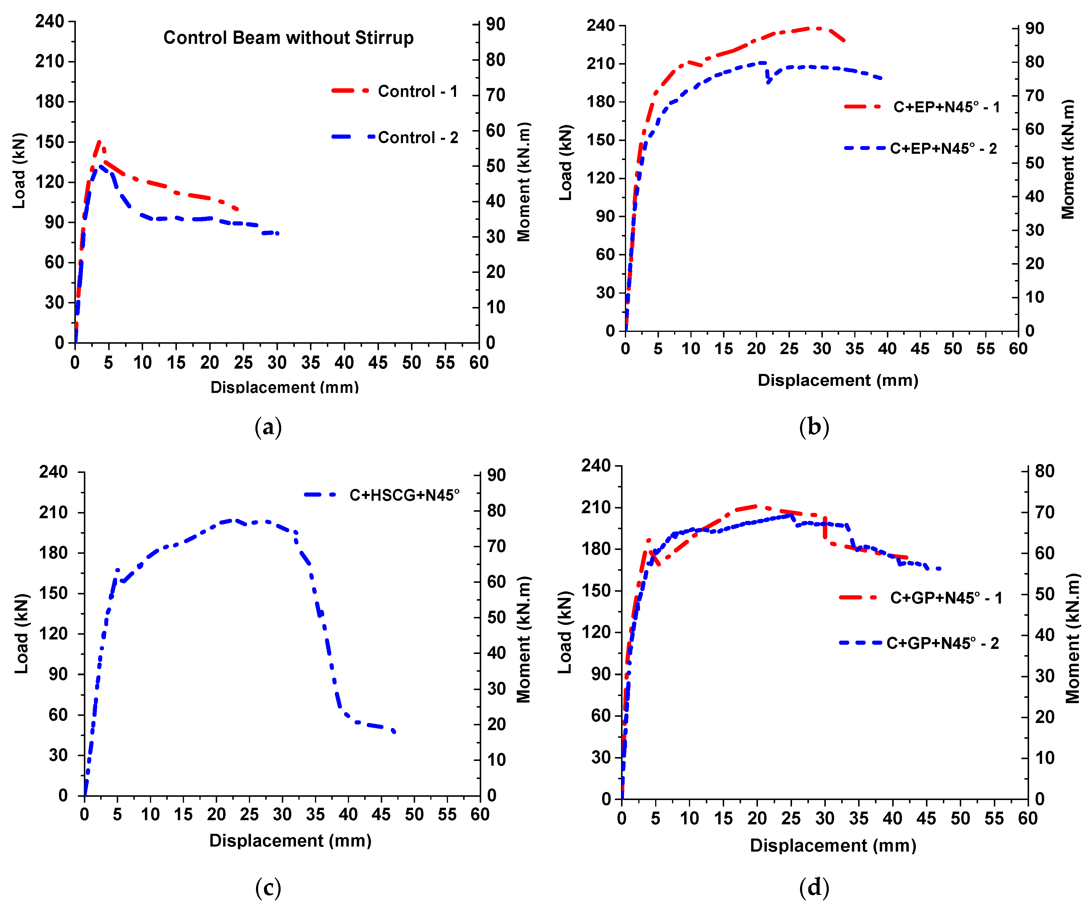
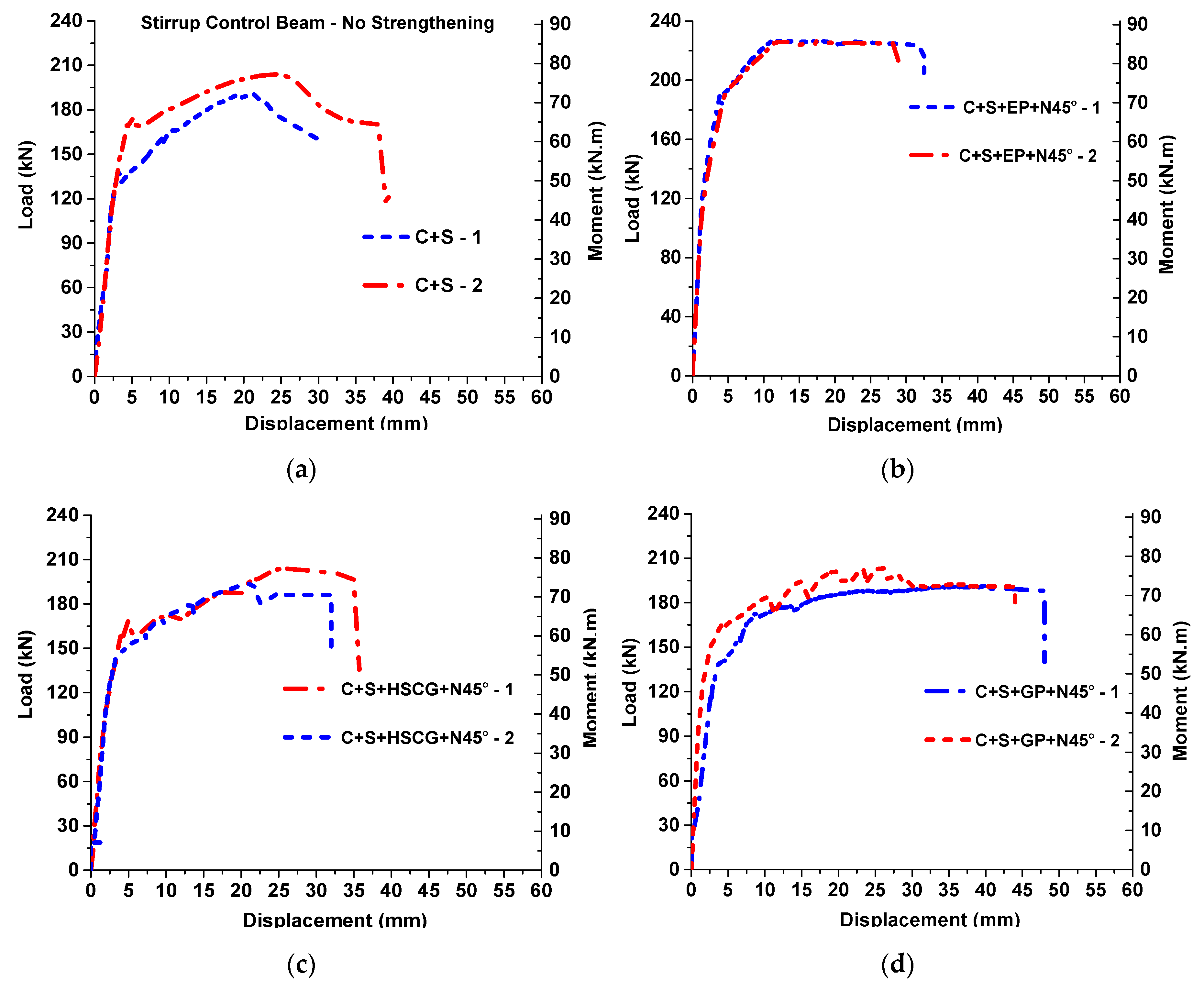
5.1. Load—Displacement Behavior
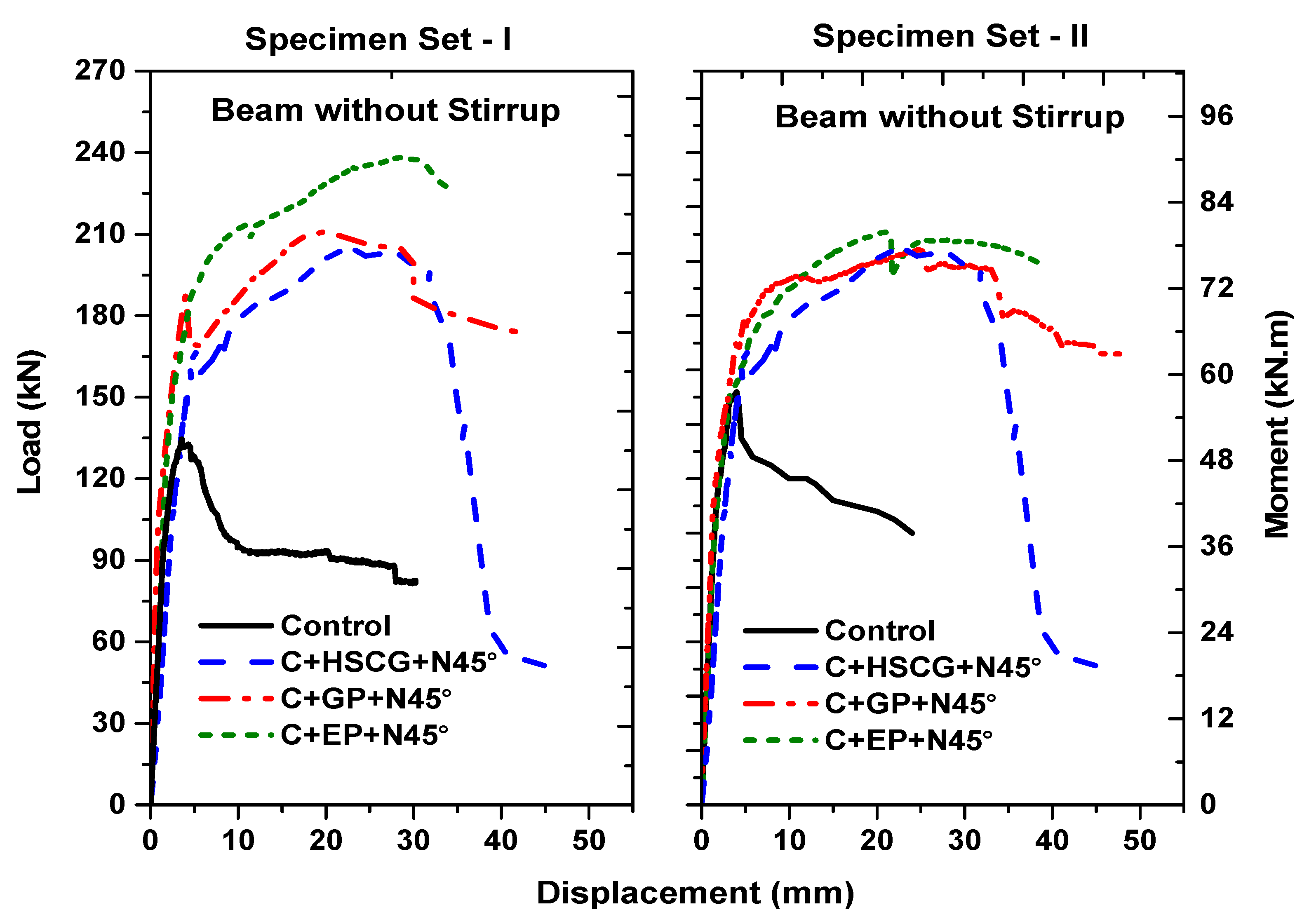
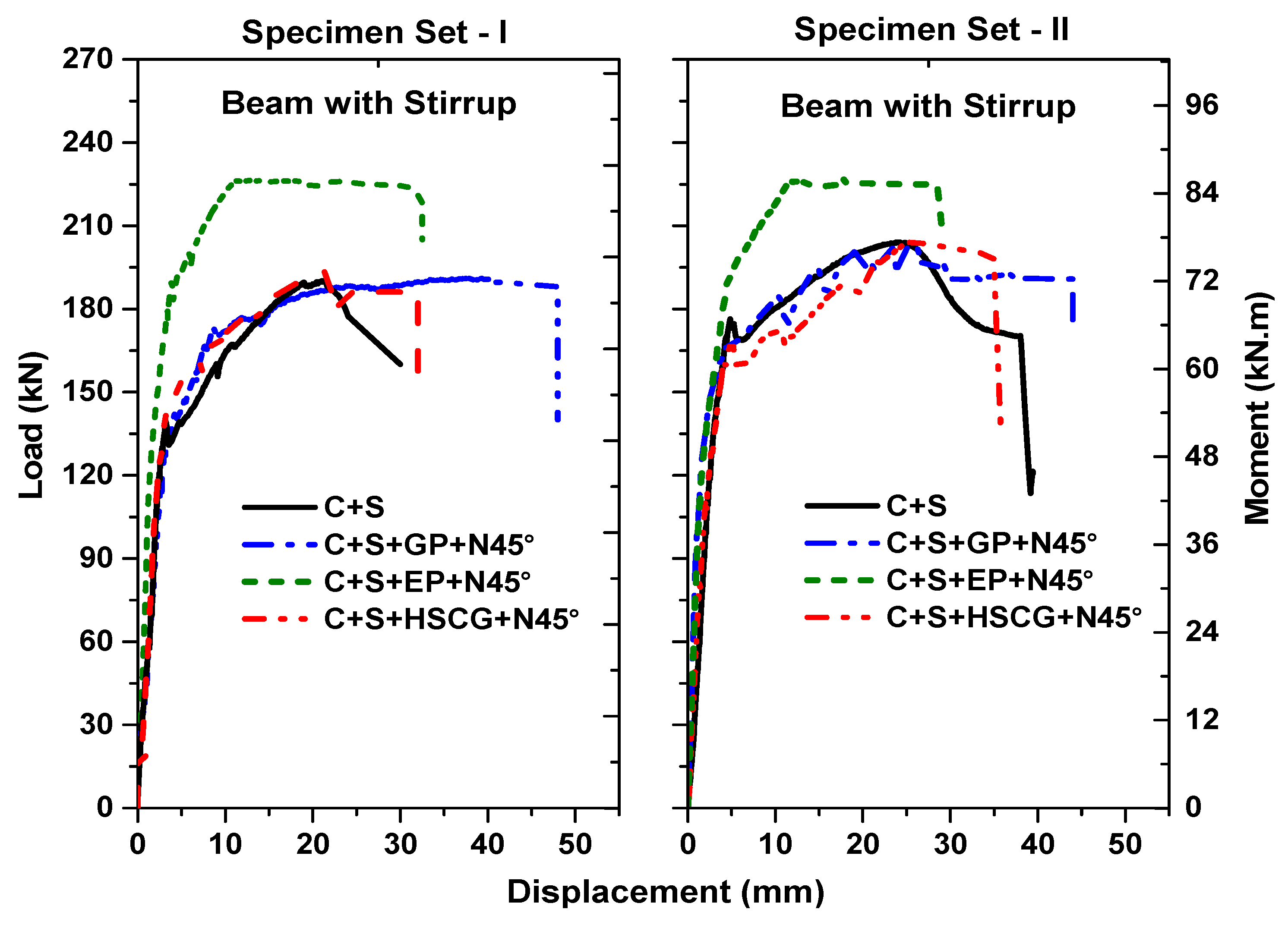
5.2. Overall Load—Displacement Behavior with and without Stirrups
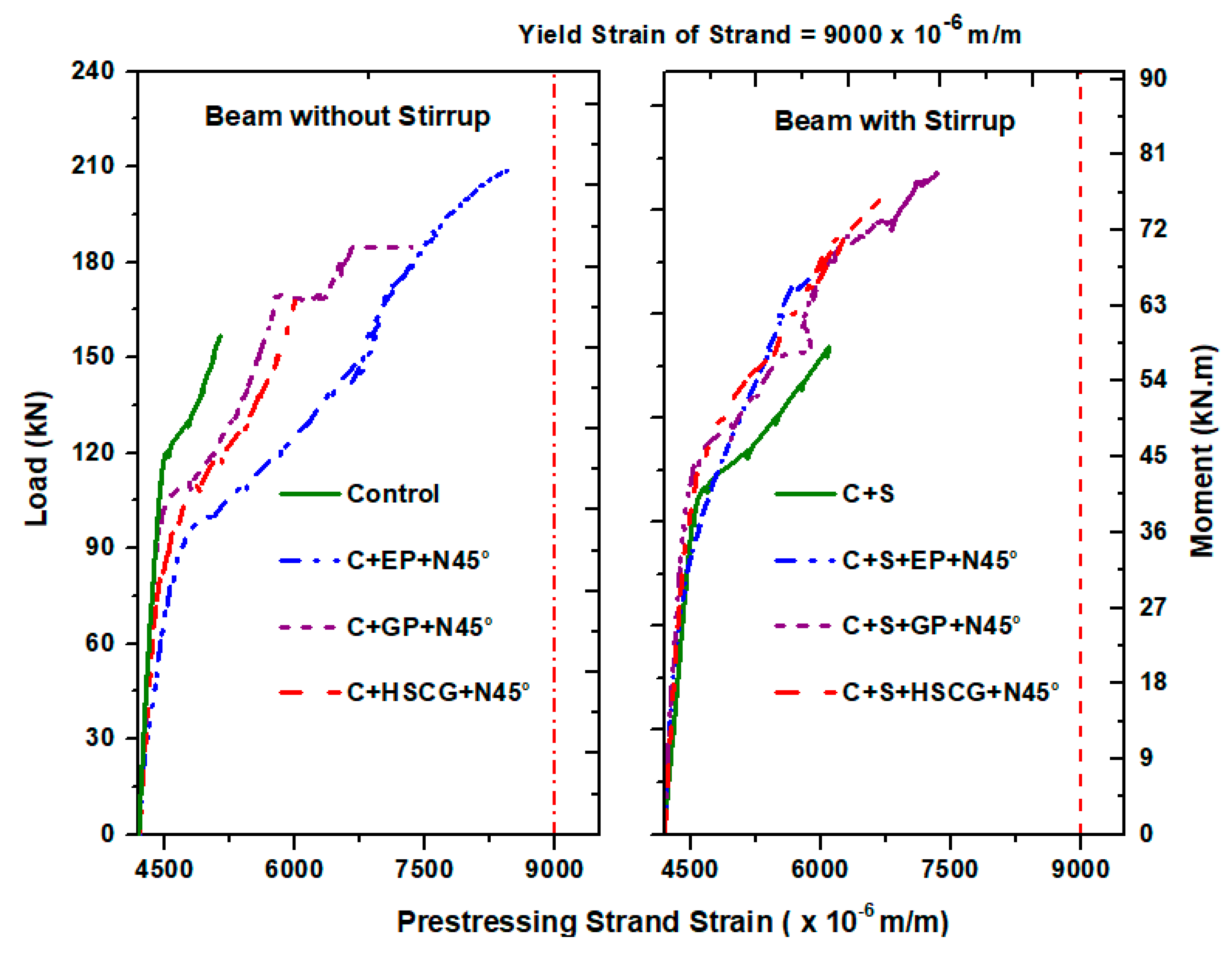
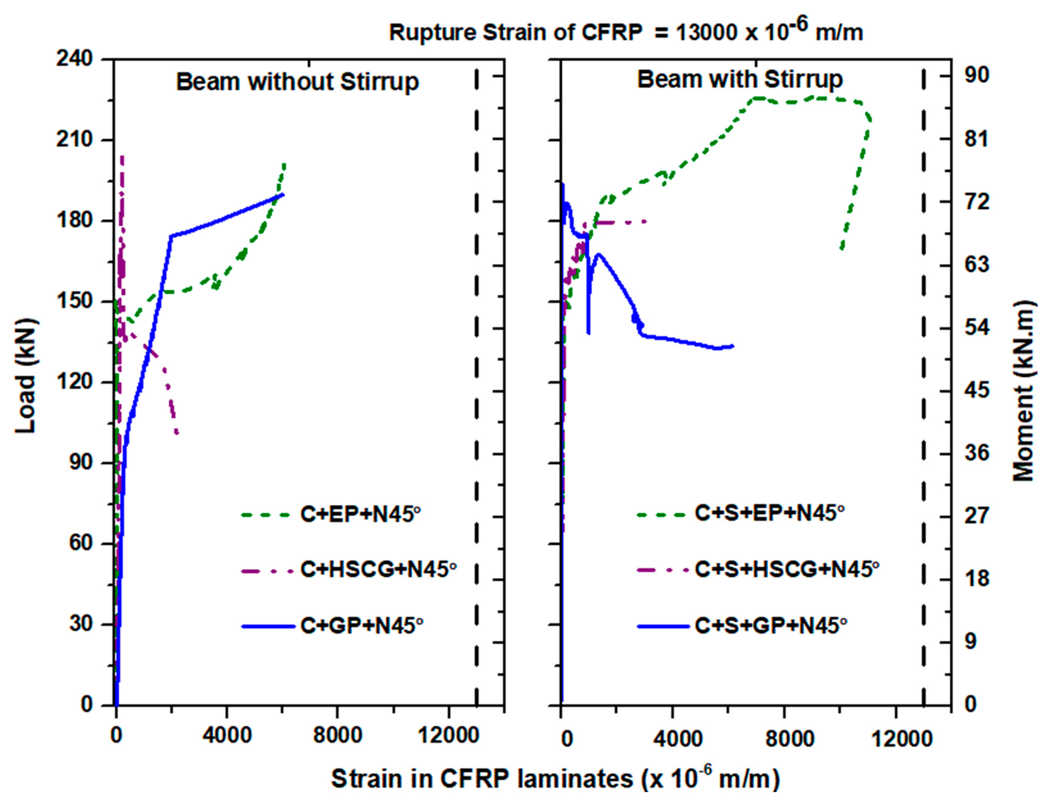
5.3. Load—Strain Behavior
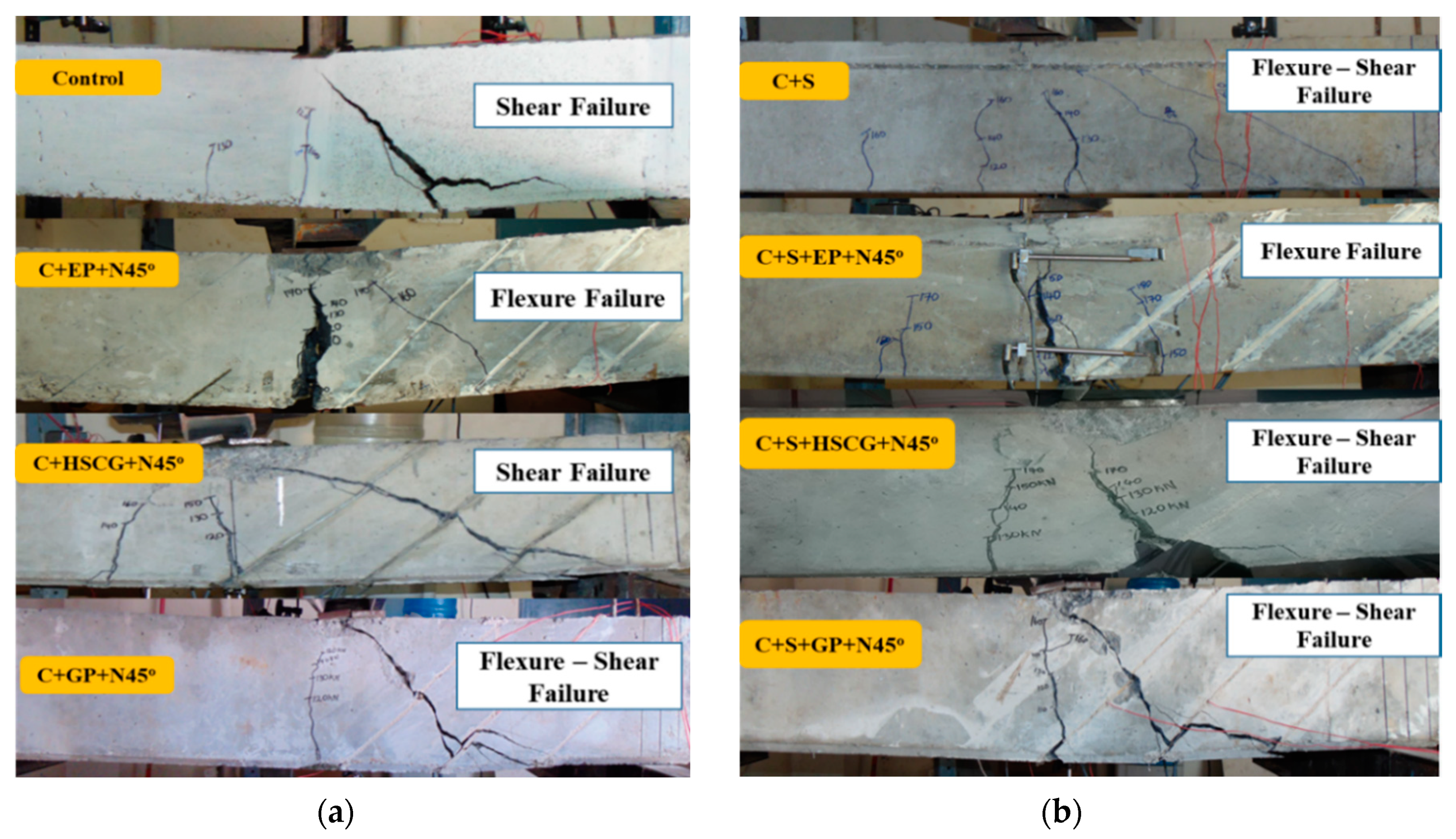
5.4. Failure Modes of PSC Beams with Different Bonding Materials
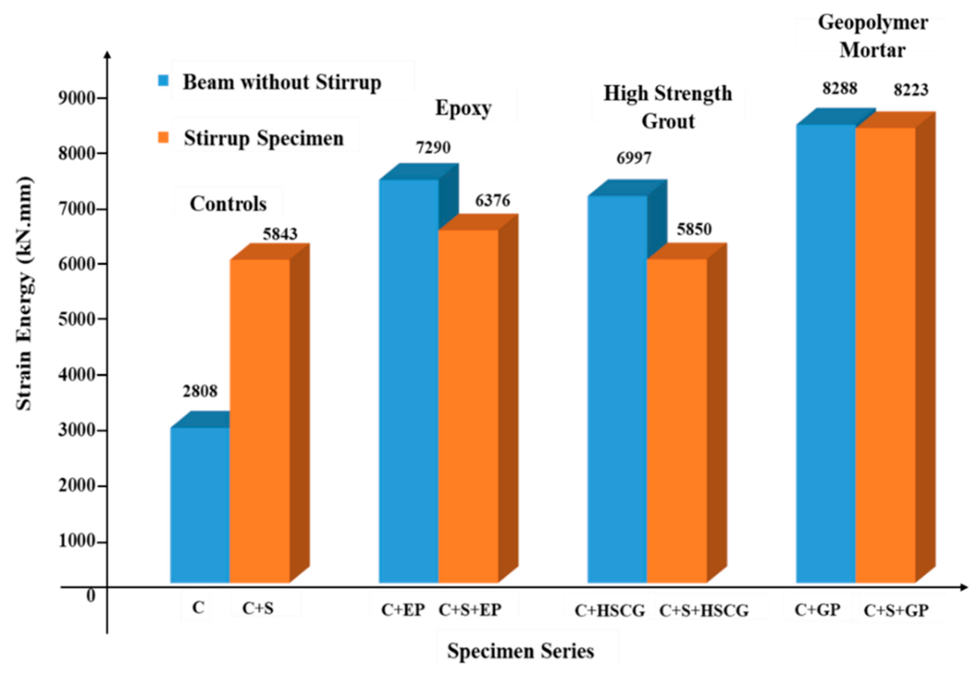
5.5. Stiffness at Cracking and Energy Absorption
6. Conclusions
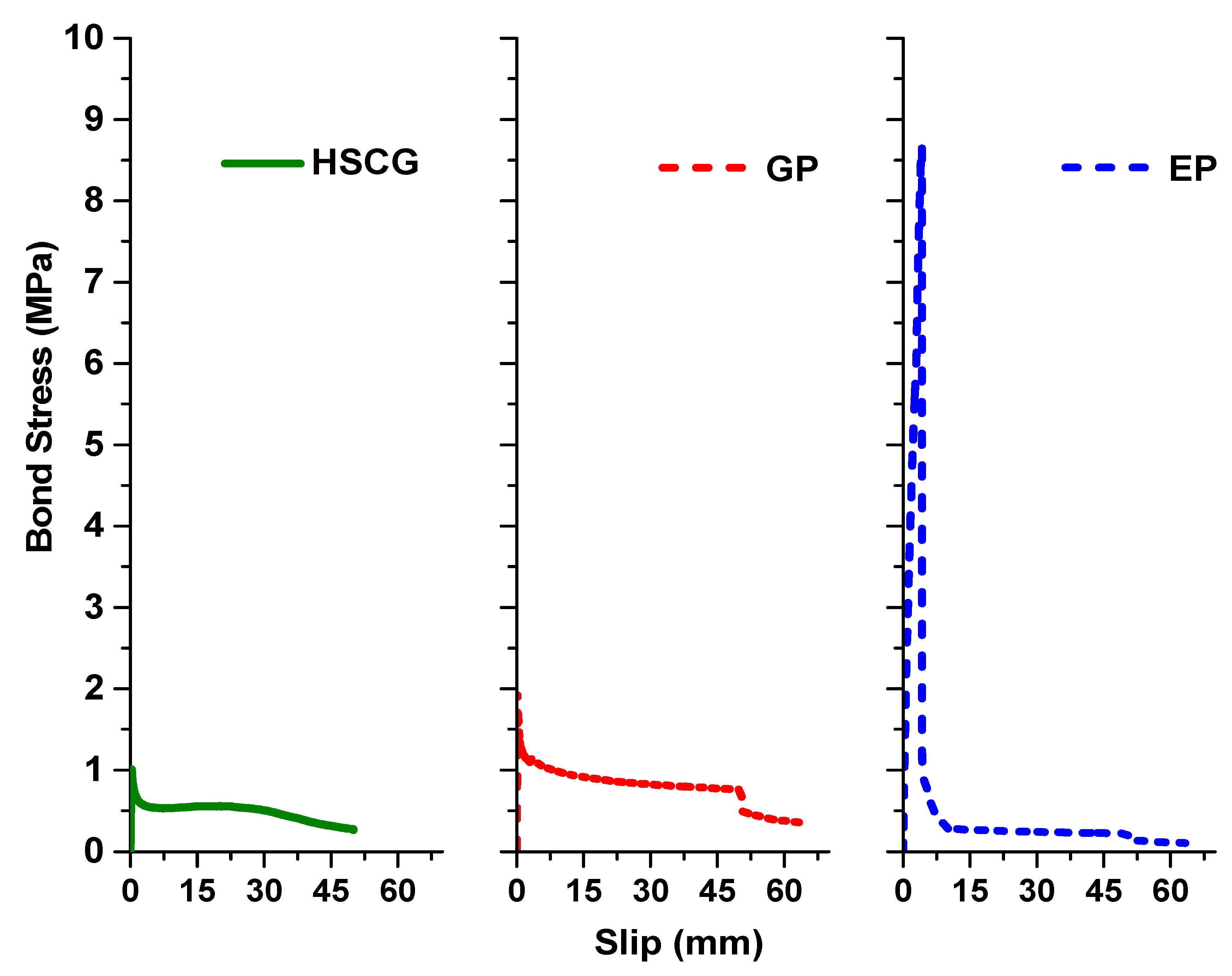
- Bond (pull-out) tests for NSM FRP laminates were carried out using different bonding materials. Epoxy had the highest bond strength, followed by high strength cement grout and geopolymer mortar.
- NSM strengthening using epoxy as bonding material resulted in good improvement in terms of peak load capacity, by 56.2% and 14.8%, for control specimens with and without stirrups, respectively.
- NSM shear strengthening of PSC beams using HSCG as bonding material improved the peak strength of beams without stirrups. However, it resulted only in marginal improvement of strength in the presence of stirrups.
- NSM strengthening of PSC beams using geopolymer as bonding material improved the peak shear strength and ultimate displacement of beams without stirrups by 44.4% and 66.7%, respectively. However, it resulted in marginal improvement of strength and good improvement in ultimate displacement (32.2%) in the presence of stirrups.
- Only a marginal difference in structural performance was observed between the geopolymer and high strength cement grout in NSM shear strengthening. Therefore, other factors such as availability, cost, and long-term durability shall be weighed while choosing the bonding material in NSM shear strengthening.
- The NSM shear strengthening reduced the width of the diagonal cracks in the post-cracking response. The NSM shear strengthening with all the bonding materials reduced the concrete surface strains at all stages of the post-cracking behavior.
Author Contributions
Funding
Conflicts of Interest
Abbreviations
| Empirical parameter taken as 0.315 in bond strength | |
| Parameters to calculate bond strength and debonding strain | |
| EP | Modulus of Elasticity of FRP laminates (MPa) |
| Principal strains calculated from LVDT rosette | |
| Strains in horizontal and vertical direction from LVDT rosette | |
| Horizontal strain measured in the compression side (Top) | |
| Horizontal strain measured in the tension side (Bottom) | |
| Diagonal strain measured from LVDT rosette arrangement | |
| tP | Thickness of FRP laminates (mm) |
| bP | Width of FRP laminates (mm) |
| bc | Width of cube specimen (mm) |
| fc’ | Compressive strength of the bonding material (MPa) |
| Le | Effective bond length (mm) |
| L | Embedded length (mm) |
| Curvature of the section (mm−1) | |
| h | Distance between the horizontal LVDTs (mm) |
References
- Sharaky, I.A.; Torres, L.; Comas, J.; Barris, C. Flexural response of reinforced concrete beams strengthened with near surface mounting fiber reinforced polymer bars. Compos. Struct. 2014, 109, 8–22. [Google Scholar] [CrossRef]
- Zhang, S.S.; Yu, T.; Chen, G.M. Reinforced concrete beams strengthened in flexure with near-surface mounted (NSM) CFRP strips: Current status and research needs. Compos. Part B Eng. 2017, 131, 30–42. [Google Scholar] [CrossRef] [Green Version]
- Breveglieri, M.; Barros, J.A.O.; Dalfré, G.M.; Aprile, A. A parametric study on the effectiveness of the NSM technique for the flexural strengthening of continuous RC slabs. Compos. Part B Eng. 2013, 43, 1970–1987. [Google Scholar] [CrossRef] [Green Version]
- De Lorenzis, L.; Teng, J.G. Near surface mounted fiber reinforced polymer reinforcement: An emerging technique for strengthening. Compos. Part B Eng. 2007, 38, 119–143. [Google Scholar] [CrossRef]
- Kankeri, P.; Prakash, S.S. Experimental evaluation of bonded overlay and NSM GFRP bar strengthening on flexural behaviour of precast prestressed hollow core slabs. Eng. Struct. 2016, 120, 49–57. [Google Scholar] [CrossRef]
- Pachalla, S.K.S.; Prakash, S.S. Effect of openings on the behaviour of PPHCS slabs under low and moderate shear. ACI Struct. J. 2017, 114, 1–10. [Google Scholar]
- Pachalla, S.K.S.; Prakash, S.S. Efficient near-surface mounted CFRP strengthening of pretensioned hollow core slabs with opening: An experimental study. Compos. Struct. 2017, 162, 28–38. [Google Scholar] [CrossRef]
- Yao, J.; Teng, J.G.; Chen, J.F. Experimental study on FRP-to-concrete bonded joints. Compos. Part B Eng. 2005, 36, 99–113. [Google Scholar] [CrossRef]
- Islam, A.K.M. Effective methods of using carbon fiber reinforced polymer in shear strengthening of concrete girders. Eng. Struct. 2009, 31, 709–714. [Google Scholar] [CrossRef]
- Rahal, K.N.; Rumaih, H.A. Tests on reinforced concrete beams strengthened in shear using Near Surface Mounted CFRP and steel bars. Eng. Struct. 2011, 33, 53–62. [Google Scholar] [CrossRef]
- Pellegrino, C.; Modena, C. Fiber Reinforced Polymer shear strengthening of Reinforced Concrete beams with transverse steel reinforcement. J. Compos. Constr. 2002, 6, 104–111. [Google Scholar] [CrossRef]
- Kuntal, V.S.; Chellapandian, M.; Prakash, S.S. Efficient near surface mounted CFRP shear strengthening of high strength prestressed concrete members—An experimental study. Compos. Struct. 2017, 180, 16–28. [Google Scholar] [CrossRef]
- Dias, S.J.E.; Barros, J.A.O. New Shear Strengthening technique with CFRP laminates applied in high T cross section RC beam. Compos. Part B Eng. 2017, 114, 256–267. [Google Scholar] [CrossRef] [Green Version]
- Barros, J.A.O.; Dias, S.J.E.; Baghi, H.; Ventura-Gouveia, A. New shear strengthening configurations of Near-Surface Mounted CFRP laminates for RC beams. ACI Struct. J. 2016, 13, 1275–1286. [Google Scholar] [CrossRef]
- Barros, J.A.O.; Dias, S.J.E. Near surface mounted CFRP laminates for shear strengthening of concrete beams. Cem. Concr. Compos. 2006, 28, 276–292. [Google Scholar] [CrossRef] [Green Version]
- Ceroni, F. Experimental performances of reinforced concrete beams strengthened with FRP materials. Constr. Build. Mater. 2010, 24, 1547–1559. [Google Scholar] [CrossRef]
- Rizzo, A.; De-Lorenzis, L. Behavior and capacity of reinforced concrete beams strengthened with NSM FRP reinforcement. Constr. Build. Mater. 2009, 23, 1555–1567. [Google Scholar] [CrossRef]
- Mofidi, A.; Chaallal, O.; Chen, L.; Chao, Y. Investigation of near surface mounted for shear rehabilitation of reinforced concrete beams using fiber reinforced polymer composites. J.Compos. Constr. 2016, 20, 1–14. [Google Scholar] [CrossRef] [Green Version]
- Rahman, M.M.; Jumat, M.Z.; Hosen, M.A.; Islam, A.B.M.S. Effect of adhesive replacement with cement mortar on NSM strengthened RC beam. Rev. La Construcción 2016, 15, 61–72. [Google Scholar] [CrossRef] [Green Version]
- Al-Mahmoud, F.; Castel, A.; Francois, R.; Tourneur, C. Strengthening of RC members with near-surface mounted CFRP rods. Compos. Struct. 2009, 91, 138–147. [Google Scholar] [CrossRef]
- Zhang, H.Y.; Hao, X.; Fan, W. Experimental study on high temperature properties of carbon fiber sheets strengthened concrete cylinders using geopolymer as adhesive. Procedia Eng. 2016, 135, 47–55. [Google Scholar] [CrossRef]
- Al-Bayati, G.; Al-Mahaidi, R.; Kalfat, R. Experimental investigation into the use of NSM FRP to increase the torsional resistance of RC beams using epoxy resins and cement-based adhesives. Constr. Build. Mater. 2016, 124, 1153–1164. [Google Scholar] [CrossRef]
- Hashemi, S.; Al-Mahaidi, R. Experimental and finite element analysis of flexural behavior of FRP-strengthened RC beams using cement-based adhesives. Constr. Build. Mater. 2012, 26, 268–273. [Google Scholar] [CrossRef]
- Al-Abdwais, A.; Al-Mahaidi, R. Modified cement-based adhesive for Near-surface mounted CFRP strengthening system. Constr. Build. Mater. 2016, 124, 794–800. [Google Scholar] [CrossRef]
- Al-Abdwais, A. Near-surface mounted CFRP application on reinforced concrete members using modified cement-based adhesive. Ph.D. Thesis, Swinburne University of Technology, Melbourne, Australia, 2015. [Google Scholar]
- Maranan, G.B.; Manalo, A.C.; Benmokrane, B.; Karunasena, W.; Mendis, P.; Nguyen, T.Q. Shear behaviour of geopolymer-concrete beams transversely reinforced with continuous rectangular GFRP composite spirals. Comp. Struct. 2018, 187, 454–465. [Google Scholar] [CrossRef]
- Chalioris, C.E.; Kosmidou, P.K.; Papadopoulos, N.A. Investigation of a New Strengthening Technique for RC Deep Beams Using Carbon FRP Ropes as Transverse Reinforcements. Fibers. 2018, 6, 52. [Google Scholar] [CrossRef] [Green Version]
- Chalioris, C.E.; Kytinou, V.K.; Voutetaki, M.E.; Papadopoulos, N.A. Repair of Heavily Damaged RC Beams Failing in Shear Using U-Shaped Mortar Jackets. Buildings 2019, 9, 146. [Google Scholar] [CrossRef] [Green Version]
- Moradi, E.; Naderpour, H.; Kheyroddin, A. An experimental approach for shear strengthening of RC beams using a proposed technique by embedded through-section FRP sheets. Comp. Struct. 2020, 238, 111988. [Google Scholar] [CrossRef]
- Chalioris, C.E.; Zapris, A.G.; Karayannis, G. U-Jacketing Applications of Fiber-Reinforced Polymers in Reinforced Concrete T-Beams against Shear—Tests and Design. Fibers 2020, 8, 13. [Google Scholar] [CrossRef] [Green Version]
- Zheng, Y.; Zhou, Y.; Zhou, Y.; Pan, T.; Zhang, Q.; Liu, D. Cracking behavior of reinforced concrete beams strengthened with CFRP anchorage system under cyclic and monotonic loading. Eng. Struct. 2020, 207, 110222. [Google Scholar] [CrossRef]
- Indian Standards 516. Methods of Test for Strength of Concrete; Amendment No. 2, Reprint 1993; Bureau of Indian Standards: New Delhi, India, 1959. [Google Scholar]
- ASTM D3039. Standard Test Method for Tensile Properties of Polymer Matrix Composite Materials; ASTM 2000; ASTM International: West Conshohocken, PA, USA, 2017. [Google Scholar]
- De-Lorenzis, L.; Nanni, A. Bond of near-surface mounted FRP rods to concrete. ACI Struct. J. 2002, 99, 123–132. [Google Scholar]
- De-Lorenzis, L.; Rizzo, A.; Tegola, A.L. A modified pull-out test for bond of near-surface mounted FRP rods in concrete. Compos. Part B Eng. 2002, 33, 589–603. [Google Scholar] [CrossRef]
- ASTM C1583. Standard test method for Tensile Strength of Concrete Surfaces and the Bond Strength or Tensile Strength of Concrete Repair and Overlay Materials by Direct Tension (Pull-off Method); ASTM International: West Conshohocken, PA, USA, 2017. [Google Scholar]
- Teng, J.G.; Smith, S.T.; Yao, J.; Chen, J.F. Intermediate crack induced debonding in RC beams and slabs. Constr. Build. Mater. 2003, 17, 447–462. [Google Scholar] [CrossRef]
- Bencardino, F.; Condello, A. Innovative solution to retrofit RC members: Inhibiting-repairing-strengthening (IRS). Constr. Build. Mater. 2016, 117, 171–181. [Google Scholar] [CrossRef]
- ACI 440.2R. Guide for the Design and Construction of Externally Bonded FRP System for Strengthening Concrete Structures; ACI Committee 440; American Concrete Institute: Farmington Hills, MI, USA, 2017. [Google Scholar]
- Kani, G. How safe are our large reinforced concrete beams? ACI Struct. J. 1967, 64, 128–141. [Google Scholar]


| Specimen ID | Number of Specimens | Presence of Stirrups | Shear Strengthening Details | Bonding Material Used | Orientation of NSM |
|---|---|---|---|---|---|
| Control | 2 | No | No strengthening | --- | --- |
| C + EP + N45° | 2 | 20 mm × 1.4 mm CFRP laminates | Epoxy resin | 45° | |
| C + CG + N45° | 2 | 20 mm × 1.4 mm CFRP laminates | HSCG | 45° | |
| C + GP + N45° | 2 | 20 mm × 1.4 mm CFRP laminates | GP | 45° | |
| C + S | 2 | Yes | No strengthening | --- | --- |
| C + S + EP + N45° | 2 | 20 mm × 1.4 mm CFRP laminates | Epoxy resin | 45° | |
| C + S + CG + N45° | 2 | 20 mm × 1.4 mm CFRP laminates | HSCG | 45° | |
| C + S + GP + N45° | 2 | 20 mm × 1.4 mm CFRP laminates | GP | 45° |
| Specimen ID. | Average Peak Load (kN) | Peak Shear Stress (MPa) | Debonding Strain | Failure Mode | |
|---|---|---|---|---|---|
| Experiment | Analytical | ||||
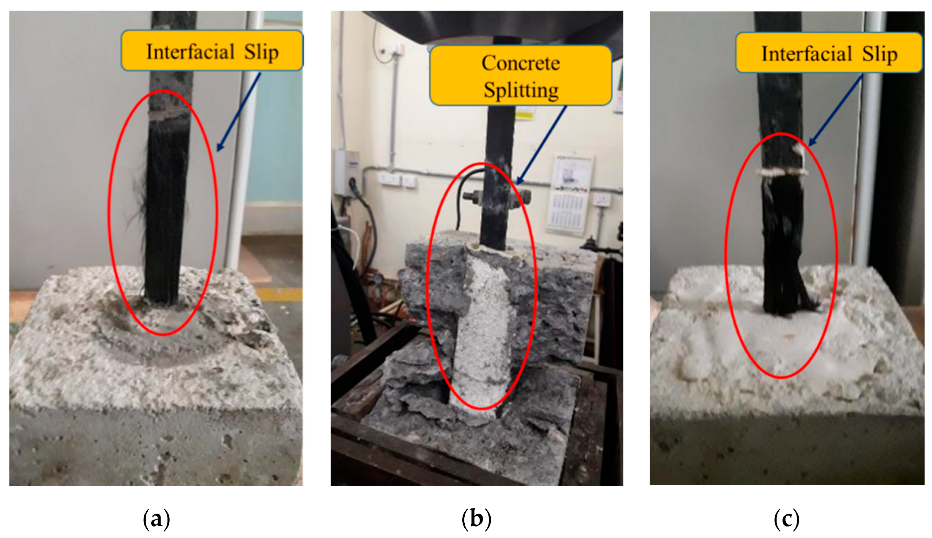
| EP | 29.9 | 8.70 | 8.73 | 0.0061 | Concrete Splitting |
| GP | 2.50 | 0.73 | 2.80 | 0.0020 | Interfacial Slip |
| HSCG | 4.50 | 1.30 | 3.40 | 0.0026 | Interfacial Slip |
| Specimen ID | Load @ First Crack (kN) | Displ. @ First Crack (mm) | Peak Load (kN) | % Increase in Peak Load | Displacement at Peak Load (mm) | Energy Absorption (kN.mm) | Ultimate Displ. (mm) | Increase in Ultimate Disp.(mm) |
|---|---|---|---|---|---|---|---|---|
| Control—1 | 100 | 1.69 | 152 | -- | 4.4 | 2740 | 24.0 | -- |
| Control—2 | 100 | 1.48 | 135 | 3.6 | 2875 | 30.0 | ||
| C + EP + N45°—1 | 130 | 2.04 | 238 | 56.2 | 28.5 | 7152 | 34.1 | 35.6 |
| C + EP + N45°—2 | 100 | 1.38 | 211 | 21.5 | 7430 | 39.2 | ||
| C + CG + N45°—1 | 120 | 2.98 | 204 | 30.5 | 22.1 | 6997 | 46.9 | 45.2 |
| C + CG + N45°—2 | 110 | 2.68 | 171 | 5.2 | -- | 31.4 | ||
| C + GP + N45°—1 | 120 | 1.38 | 211 | 44.4 | 25.2 | 7812 | 42.2 | 66.7 |
| C + GP + N45°—2 | 120 | 1.65 | 204 | 20.5 | 8764 | 48.1 | ||
| C + S—1 | 110 | 2.21 | 204 | -- | 24.8 | 6894 | 39.4 | -- |
| C + S—2 | 110 | 2.25 | 190 | 18.9 | 4793 | 30.2 | ||
| C + S + EP + N45°—1 | 110 | 1.04 | 226 | 14.8 | 12.1 | 6800 | 28.5 | −14.0 |
| C + S + EP + N45°—2 | 120 | 1.54 | 226 | 11.3 | 5953 | 32.5 | ||
| C + S + CG + N45°—1 | 120 | 2.35 | 194 | 1.6 | 20.9 | 5397 | 32.1 | −2.6 |
| C + S + CG + N45°—2 | 120 | 2.44 | 205 | 25.9 | 6303 | 35.7 | ||
| C + S + GP + N45°—1 | 110 | 2.06 | 203 | 0.6 | 26.4 | 8066 | 44.0 | 32.2 |
| C + S + GP + N45°—2 | 120 | 1.45 | 192 | 37.5 | 8380 | 48.0 |
© 2020 by the authors. Licensee MDPI, Basel, Switzerland. This article is an open access article distributed under the terms and conditions of the Creative Commons Attribution (CC BY) license (http://creativecommons.org/licenses/by/4.0/).
Share and Cite
Kuntal, V.S.; Chellapandian, M.; Prakash, S.S.; Sharma, A. Experimental Study on the Effectiveness of Inorganic Bonding Materials for Near-Surface Mounting Shear Strengthening of Prestressed Concrete Beams. Fibers 2020, 8, 40. https://0-doi-org.brum.beds.ac.uk/10.3390/fib8060040
Kuntal VS, Chellapandian M, Prakash SS, Sharma A. Experimental Study on the Effectiveness of Inorganic Bonding Materials for Near-Surface Mounting Shear Strengthening of Prestressed Concrete Beams. Fibers. 2020; 8(6):40. https://0-doi-org.brum.beds.ac.uk/10.3390/fib8060040
Chicago/Turabian StyleKuntal, Vikas Singh, M. Chellapandian, S. Suriya Prakash, and Akanshu Sharma. 2020. "Experimental Study on the Effectiveness of Inorganic Bonding Materials for Near-Surface Mounting Shear Strengthening of Prestressed Concrete Beams" Fibers 8, no. 6: 40. https://0-doi-org.brum.beds.ac.uk/10.3390/fib8060040