
Synthesis and Transformation of Hollow Rutile Titania Wires by Single Spinneret Electrospinning with Sol-Gel Chemistry


Department of Chemical, Biomolecular and Corrosion Engineering, The University of Akron, Akron, OH 44325, USA
*
Author to whom correspondence should be addressed.
Fibers 2021, 9(3), 18; https://0-doi-org.brum.beds.ac.uk/10.3390/fib9030018
Submission received: 24 January 2021
/
Revised: 15 February 2021
/
Accepted: 26 February 2021
/
Published: 6 March 2021
Abstract
:The work described below was carried out to understand how to control the morphology of nanostructured titania calcined from electrospun nanofibers. This is the first report of hollow rutile nanofibers synthesized from electrospun nanofibers with short calcination time. Titanium isopropoxide was incorporated into the nanofibers as the titania precursor. The electrospinning technique was used to fabricate ceramic/polymer hybrid nanofibers. The electrospun nanofibers were then calcined to produce rutile titania nanofibers with different morphologies (hollow or solid nanofibers), which were characterized by SEM and TEM. The initial concentration of ceramic precursor and the calcination time were shown to control the morphology of the nanofiber. The hollow morphology was only obtained with a concentration of the precursor within a certain level and with short calcination times. The heat treatment profile contributed to particle growth. At longer times, the particle growth led to the closure of the hollow core and all the nanofibers resembled strings of solid particles. A formation mechanism for the hollow nanofibers is also proposed.
1. Introduction
One-dimensional titania nanostructures have been used in different applications based on their morphology. Applications include dye-sensitized solar cells [1,2,3], water splitting cells [4], gas sensors [5,6,7], and lithium batteries [8]. One-dimensional TiO2 structures are typically categorized into one of several morphologies, including nanotubes, nanorods, nanowires, and nanofibers. Nanotubes and nanorods are straighter, whereas nanofibers and nanowires have significant curvature [9,10]. Nanotubes can be produced as either single-layer [11] or asymmetric multi-layer tubes [12] depending on the synthesis technique. With the thickness of a single layer being a few nanometers [9,13,14], the surface area and pore volume per unit volume are significantly increased and this enhances surface reactivity [14]. Titania nanorods [15] are believed to provide an effective and long-distance electron-transport pathway for photogenerated electrons. [6,16,17] Nanofibers, defined as fibers with diameter ranges below 1000 nm, are usually obtained by calcining a polymer nanofiber containing a ceramic precursor to remove the organic polymer. The applications vary significantly depending on the fiber and grain size [18,19,20,21].
At present, many ceramic materials have been made into hollow fiber by the electrospinning route [11,18,19,22,23,24,25,26,27,28,29,30]. Different formation mechanisms have been proposed. From the synthesis of hollow CuO [31] and ZnO [32] fibers made by electrospinning with sol–gel chemistry, a mechanism involving the phase separation of a ceramic dense shell and polymer dense core was proposed. It was suggested that a concentration gradient of ceramic precursor is established as the metal organic near the fiber surface is consumed and crystallized into pure ceramic material. It was proposed that this concentration gradient drives the ceramic precursor’s diffusion outward, with the polymer remaining in the core. After full pyrolysis of the polymer core, a hollow structure formed. In their study of titanium and vanadium oxide complexes, Zhao et al. [27] proposed a multi-layer tube-in-tube structure with a polymer oxidation mechanism. Zhao believed that the presence of oxygen in the calcining environment is a crucial factor for the transformation of the precursor to titanium oxide. According to their mechanism, at the beginning, the oxygen diffuses from the gas phase into the surface of the polymer and causes oxidative degradation and subsequent removal of the polymer. As the removal of the polymer continues, the distance between inorganic grains is reduced, thus accelerating the crystallization of the inorganic grains. As a result, a rigidly crystallized shell is formed. Eid et al. [33] also reported an atmosphere inducible morphology change between solid and hollow fiber based on their study of iron oxide fibers made from electrospun precursors. Another approach to synthesizing hollow fibers through the electrospinning method was to precisely control the calcination profile. However, even with the same material, i.e., iron oxide, Cheng et al. [34] provided a different mechanism from the diffusion point of view. Cheng believed that the formation of hollow fibers was because of a gel layer on the surface of the polymer fiber. This gel layer was caused by solvent evaporating during calcination and controlling the diffusion of decomposed gas from inside out. If the decomposition rate of the polymer was higher than the diffusion rate, pressure built up inside the shell and sustained the hollow structure. Otherwise, the hollow structure collapsed because of a contraction force. Last but not least, the most complete research on TiO2 nanofibers was carried out by Lang [11]. Lang calcined the TiO2/PVP as spun fiber at 500 °C for 4 h, resulting in a tube-in-tube structure with both anatase and rutile crystallinity. For the formation mechanism, Lang proposed an idea similar to the diffusion theory plus the concentration of the precursor. If the concentration of the precursor is high enough, the ceramic particles are able to fill the whole fiber after the decomposition of the polymer. Otherwise, hollow fibers are obtained.
The work described below was carried out to understand how to control the morphology of electrospun nanostructured titania in rutile form. Synthesis of hollow anatase fibers has been previously reported by the single spinneret electrospinning method but this is the first report of hollow rutile fibers synthesized from electrospun fibers with a much shorter calcination profile.
2. Materials and Methods
2.1. Solution Preparation
Ceramic/polymer fibers were electrospun with different concentrations (low, medium, and high) of ceramic precursor (Table 1). Solutions prepared for electrospinning were made up of ceramic precursor solution and polymer solution. To obtain the titanium dioxide ceramic precursor solution, titanium isopropoxide (TIP) was mixed with an acetic acid–ethanol mixture (1:1, volume ratio) and stirred overnight to obtain a clear, light-yellow solution. The gelation of the ceramic precursor was fixed by stirring time and concentration of added acid solution, which served as a catalyst. By doing so, the degree of gelation and the size of the nuclei were controlled in similar conditions across the three recipes [35,36,37]. For the polymer solution, polyvinylpyrrolidone (PVP) was dissolved in either ethanol or a N,N-dimethylformamide (DMF)—chloroform mixture (1:1, volume ratio). Then, the precursor solution was mixed with the polymer solution with continuous stirring for 30 min. Concentration of ceramic precursor in this project is defined as the amount of ceramic precursor dispersed in the polymer with units of gram per gram of PVP and adjusted to 0.05, 0.62, and 1.5 g/g PVP.
2.2. Materials
Polyvinylpyrrolidone (PVP, MW 1300,000), titanium isopropoxide (TIP, 97%), chloroform (ACS reagent, ≥99.8%), and reagent alcohol (ethanol) (ACS grade) were purchased from Sigma-Aldrich. N,N-dimethylformamide (DMF, 99.9%) was purchased from Fisher Chemical. Acetic acid (AA, 99 wt %) was purchased from EMD. All of the chemicals were directly used without further purification.
2.3. Electrospinning
The as-prepared electrospinning solution was loaded into a 5-mL syringe with a 21-gauge stainless steel needle and fixed on the syringe pump. The applied voltage, tip-to-collector distance, and pumping rate were set depending on the solution (Table 2). The humidity of the surrounding was kept under 15% relative humidity in a humidity-controlled chamber. For the grounded collector, a piece of aluminum foil was wrapped around a conductive roller that was then rotated at a constant rotation rate of 10 rpm. Due to the composition of the solution, the parameters of the electrospinning apparatus differed between recipes. The composition of the solution and parameters of electrospinning interacted with each other. The adjustment/tuning of the electrospinning parameters was done to produce nanofibers with an average diameter of between 850 and 1600 nm and a smooth surface.
2.4. Calcination Profiles
The as-spun fibers were collected on the aluminum foil, moved to a ceramic dish, and then heated up to 950 °C and held (soaked) at that temperature to eliminate the polymer matrix and control the phase of the ceramic material. The different heating rates and soaking times shown in Table 3 were used to determine the impact on particle size and fiber morphology.
2.5. Characterization
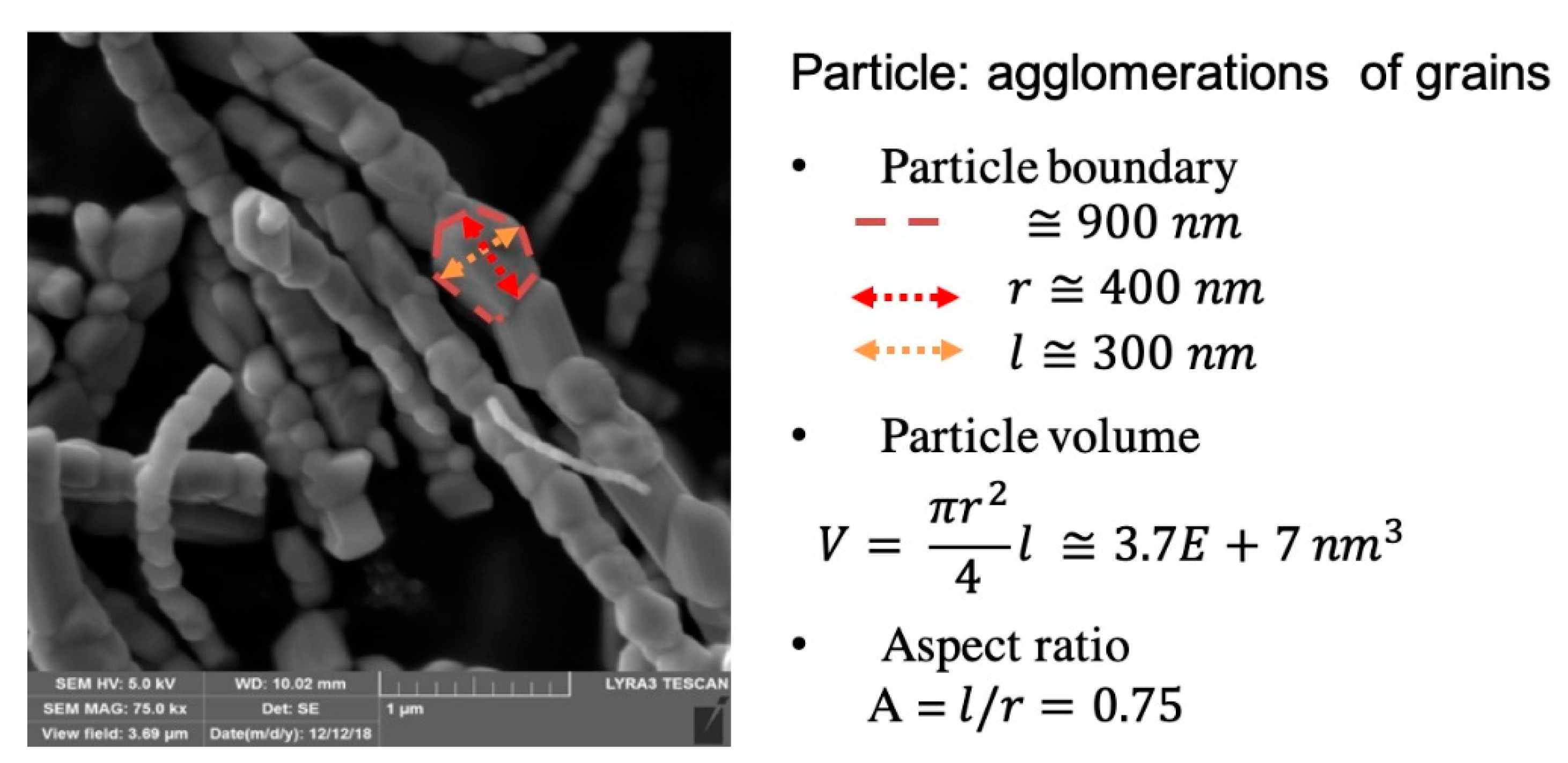
A Vecstar Ltd. (model no. MF4) furnace was used to calcine the fibers. FTIR was used to determine the composition of as-spun fiber and calcined fibers. A scanning electron microscope, SEM (FEI Quanta 200 at 30 kV and HITACHI TM3000 at 15 kV), and a transmission electron microscope (TEM FEI Tecnai G2-F20) were used to obtain the morphology of as-spun and ceramic nanofibers. The FibraQuant 1.3 software (nanoScaffold Technologies, LLC, Chapel Hill, NC, USA) was adapted to measure the fiber size and particle size distribution. The particle size was manually measured from SEM images, as shown Figure 1, and confirmed with transmission electron microscopy. The crystal structure was analyzed by X-ray diffraction (copper X-ray with wavelength 1.540 Angstrom, 40 kV, 35 mA).
3. Results
3.1. Ceramic Nanofiber Confirmation
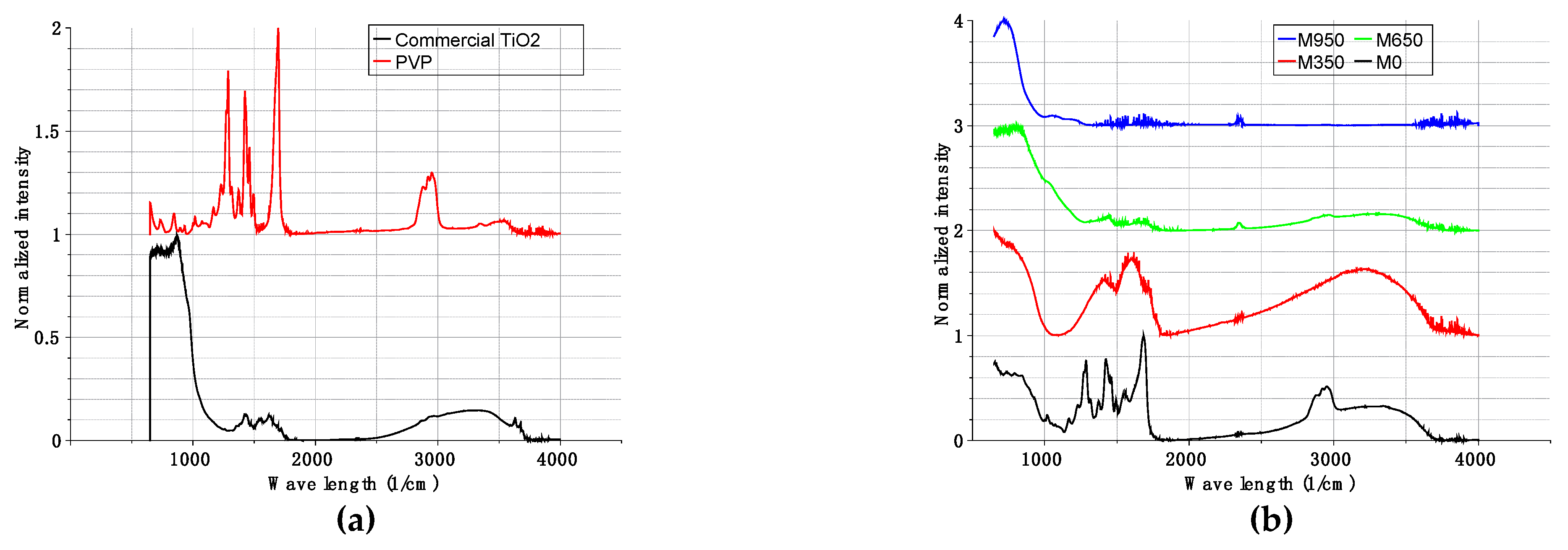
The FTIR spectrum confirmed that after calcination, the fiber was completely converted to titania. In Figure 2a, characteristic IR absorption peaks for pure PVP and commercial TiO2 powder are presented. For PVP, the absorption peaks between 1250 and 1650 cm−1 corresponded to C-N and C=O stretching motion, respectively. The other two absorption peaks around 1409 and 2876 cm−1 are from C–H bonding. [38] For TiO2, the broad absorption peaks centered at 664 cm−1 are attributed to stretching of the Ti-O-Ti bond. The absorption at 3000–3500 cm−1 was due to the hydroxyl vibration. The as-spun fiber with ceramic precursor shows peaks from both TiO2 and PVP (Figure 2b). After calcination at 650 °C, peaks of PVP almost disappeared, indicating the decomposition of PVP. At 950 °C, only peaks attributed to TiO2 were detected, indicating that the polymer matrix was fully pyrolyzed.
3.2. Nanofiber Morphology
In order to have a systematic observation with regard to the concentration of precursor and heat treatment, fiber samples with different precursor concentrations were calcined under the different calcination profiles. The morphology of the final products was observed by SEM and TEM. The maximum soaking temperature was chosen as 950 °C in order to fully pyrolyze the PVP and form pure rutile titania. The calcination profiles followed were shown in Table 3. Green as-spun polymer/ceramic hybrid fiber and samples from recipe R2400-0h (2400 °C/h heating rate without soaking), R600-0h (600 °C/h heating rate without soaking), and R600-24h (600 °C/h heating rate with 24 h soaking) were used for comparison. All of the samples were cooled at 150 °C/h. The corresponding total heat treatment time was increased from 6.6 to 31.7 h, which corresponds to R2400-0h to R600-24h in calcination profile.
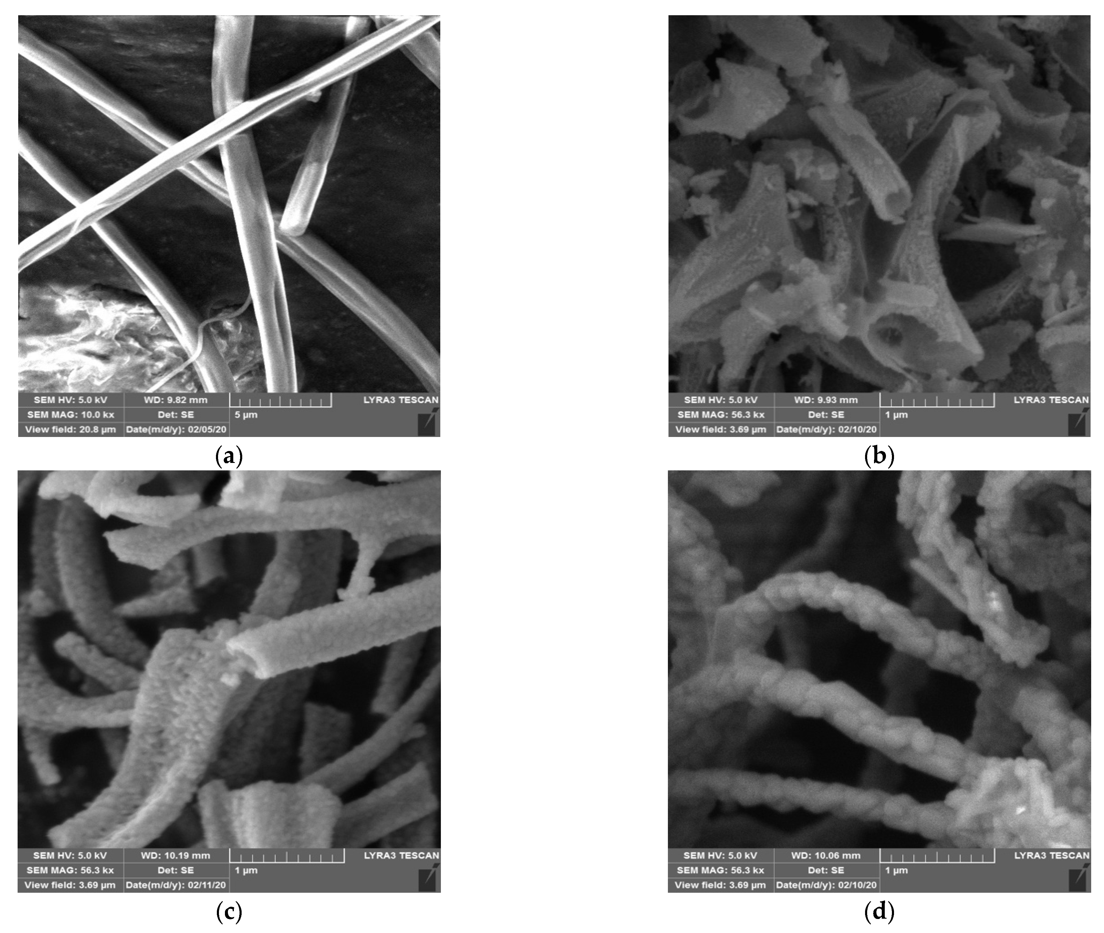
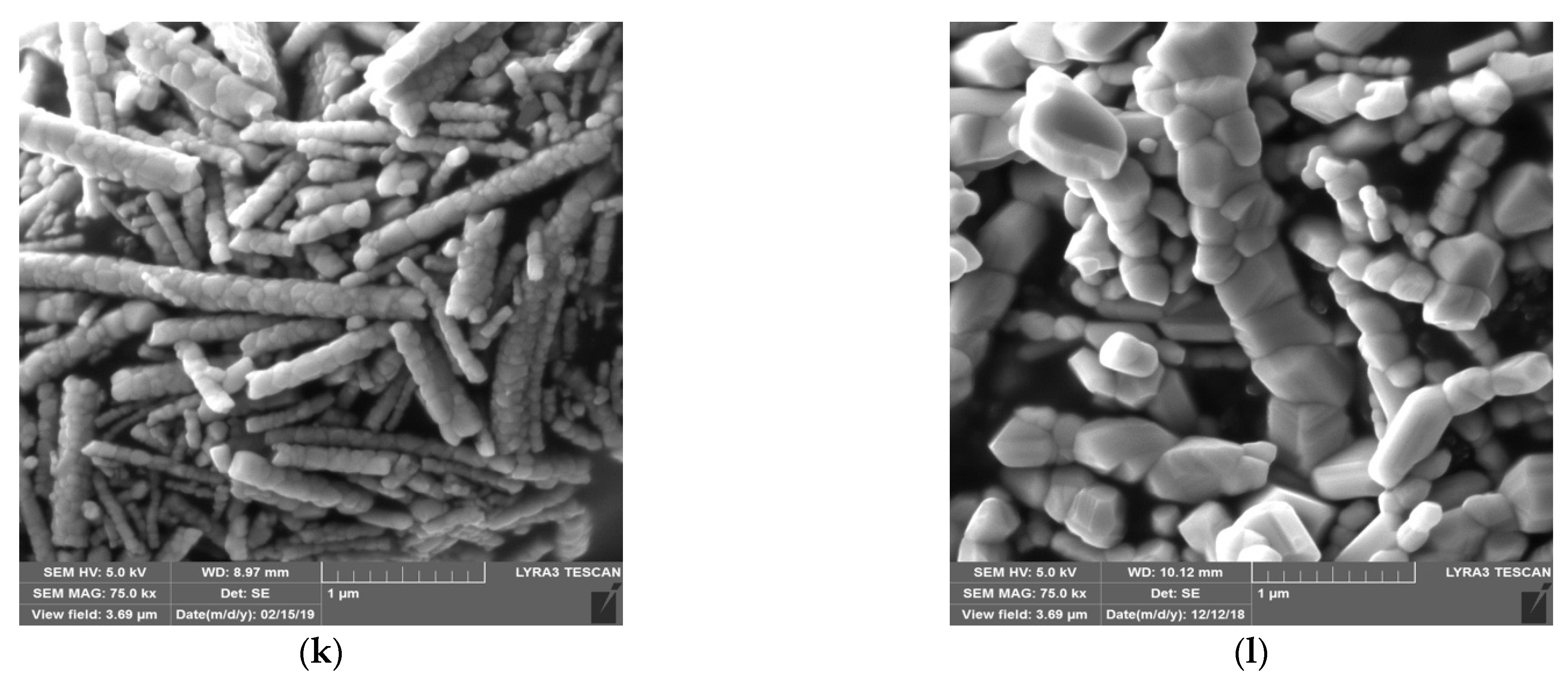
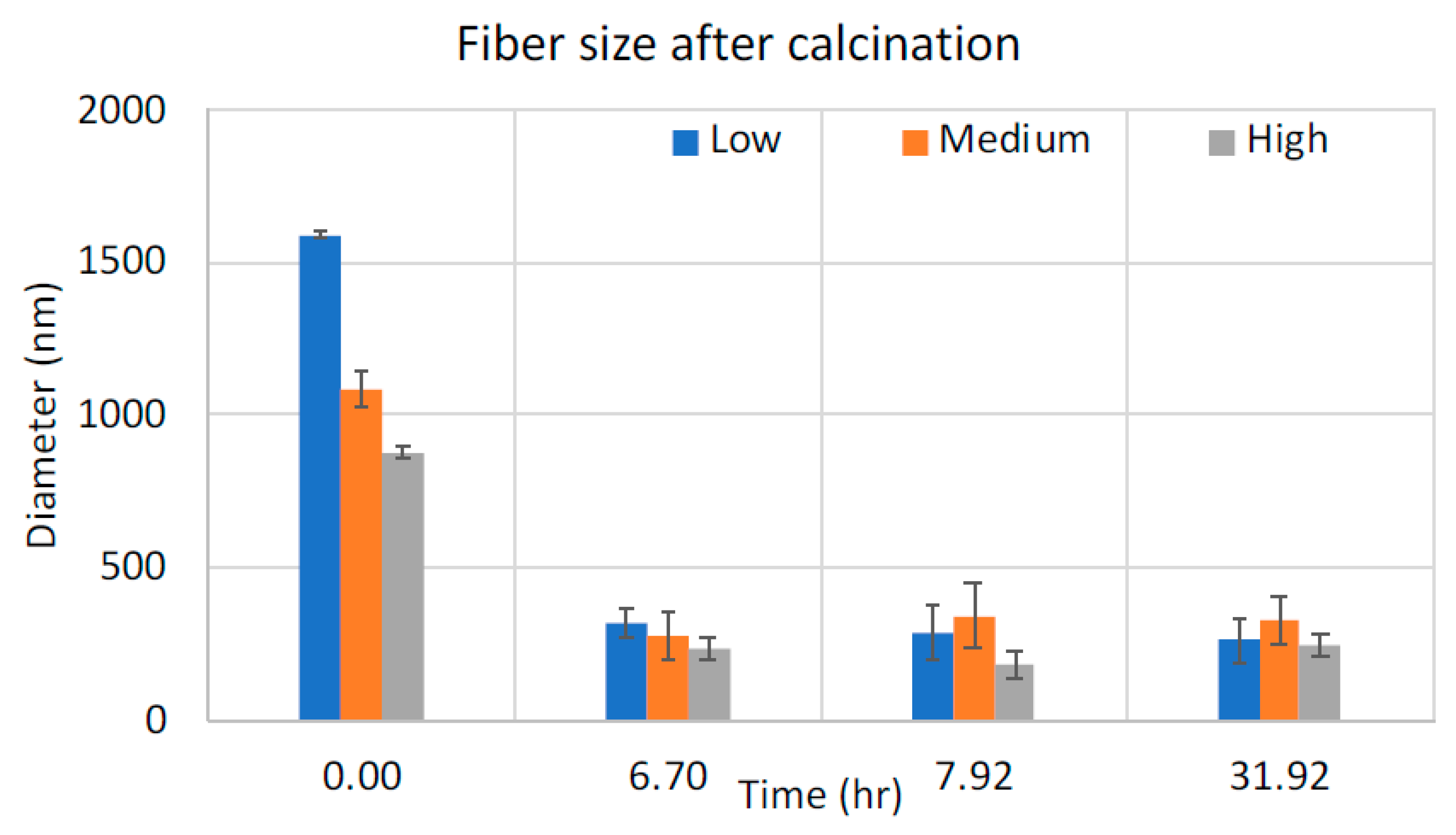
As shown in the leftmost images in Figure 3, the as-spun fibers for all samples were smooth. When exposed to the rapid ramping calcination profile (R2400-0h), the low-concentration sample presented a mixture of incomplete wall and hollow fibers with very thin walls, while medium-concentration samples produced more uniform hollow fibers with thicker walls. The sample with a high concentration of ceramic precursor formed a solid fiber shape, with shell wall thickness equal to the fiber radius. The as-spun fiber for all samples showed a significant reduction in radius at this stage, as shown in Figure 4. This was considered to be due to the loss of the polymer matrix and the condensation of ceramic particles.
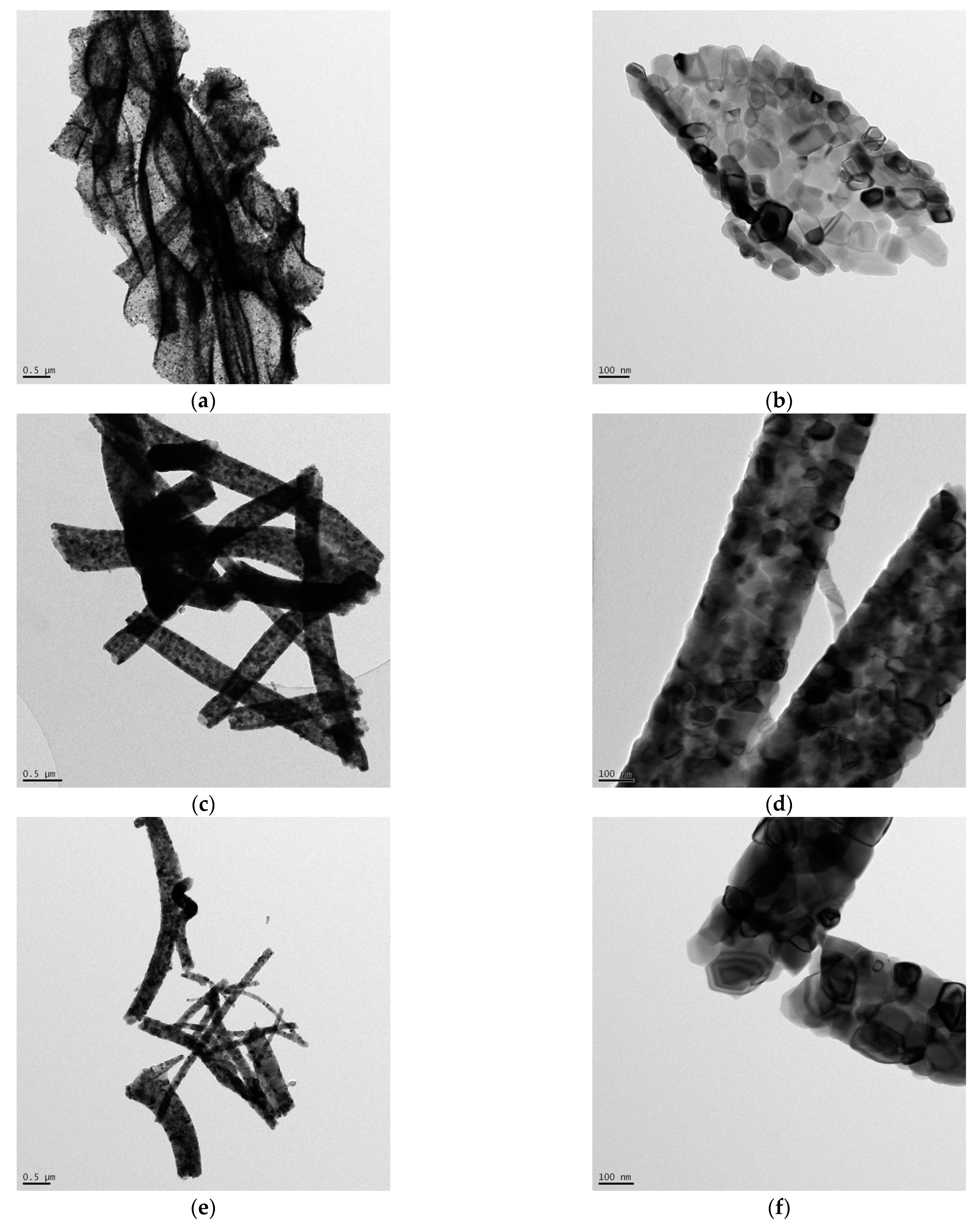
The same relation between the concentration of precursor and morphology of calcined fiber with the rapid ramping calcination profile observed by SEM was also found by TEM (Figure 5). The low-concentration sample produced an incomplete fiber or flake-like material with a more transparent wall. For the medium-concentration sample, the hollow fiber morphology was more defined. The contrast between wall and core indicated the hollow structure. With increased concentration of ceramic precursor, the calcined fiber had a fiber morphology without contrast in the TEM image, suggesting that a solid fiber was formed. When total heating was prolonged from 6.6 to 7.7 h by slowing the ramping from 2400 °C/h down to 600 °C/h, the morphology for each sample did not change significantly. Lastly, when the samples were soaked for 24 h, all samples ended up in a solid fiber form. The calcined fibers for all concentrations of precursor at this stage appeared to be composed of a string of particles.
3.3. Particle Size and Aspect Ratio
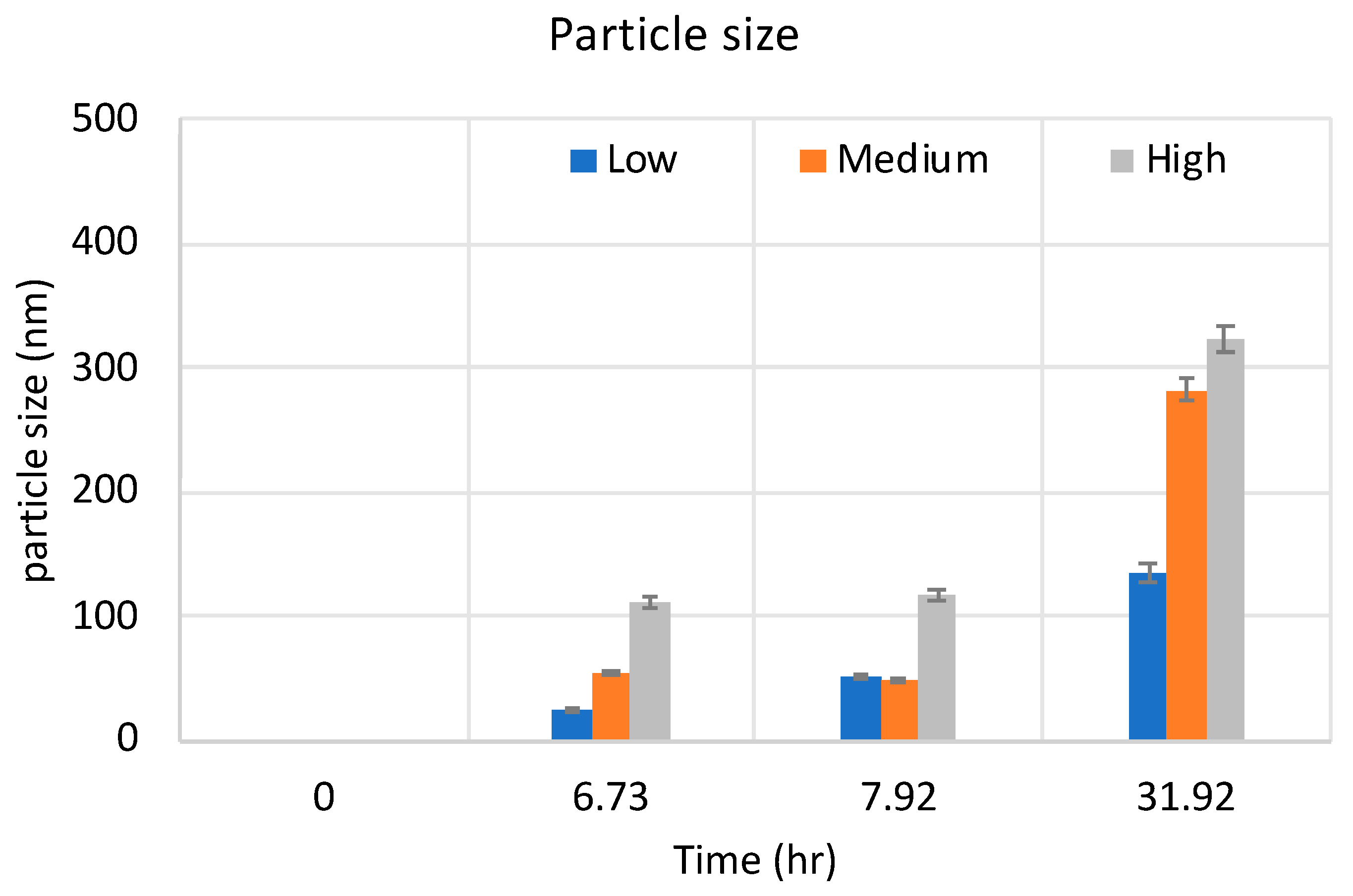
The particles grew as the concentration of ceramic precursor and soaking time increased (Figure 6). The higher the concentration of precursor and the longer heat treatment, the bigger the particle. At the highest concentration of precursor, the first observed particle was large enough to fill the tube volume, while fibers appeared in hollow structures at medium and low concentrations of precursor.
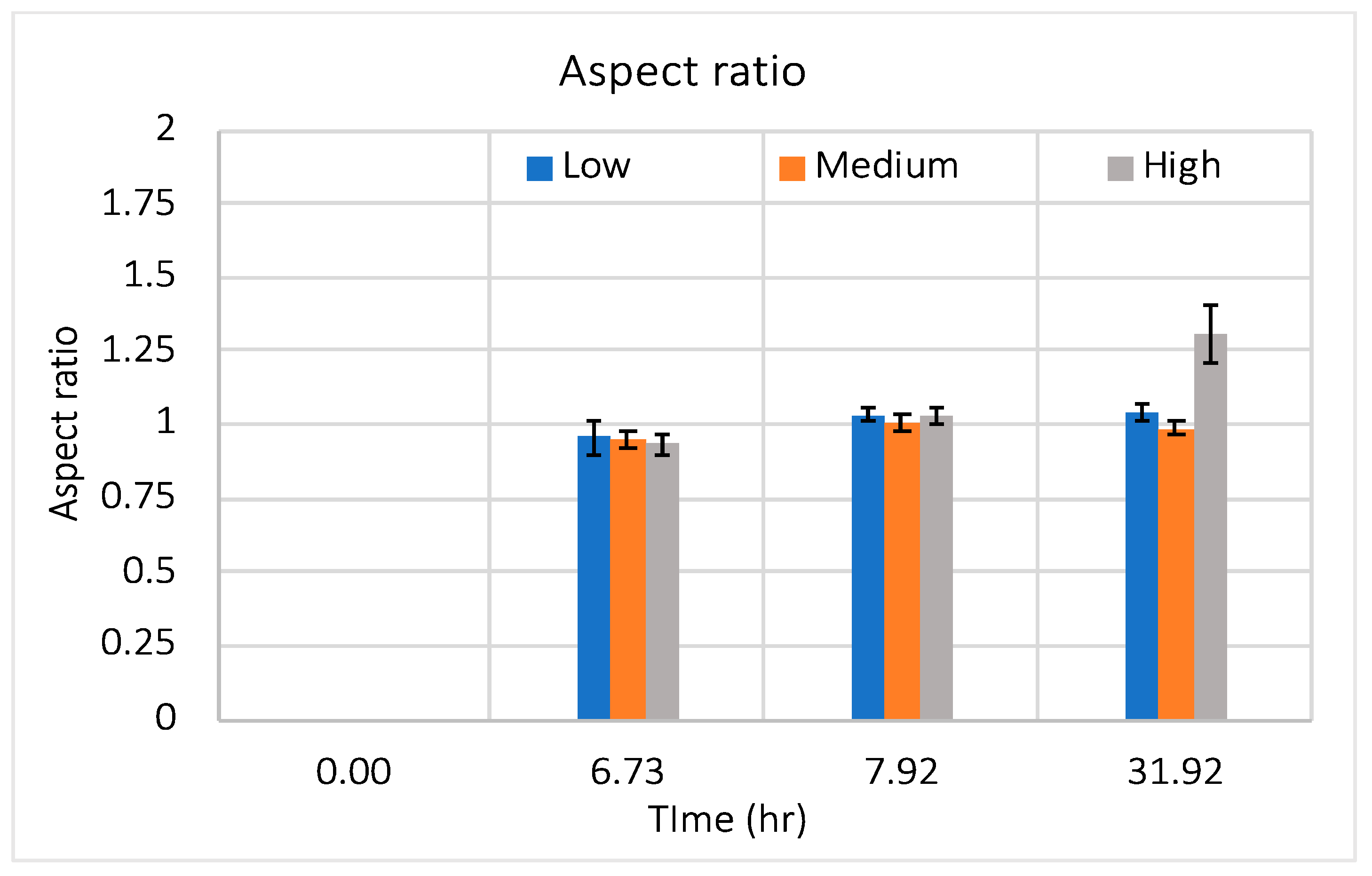
However, the aspect ratios of the particles, which is the particle size in the longitudinal direction divided by the size in the radial direction, for all calcined samples were almost always equal to one (except in high-concentration sample soaked for 24 h), indicating that the growth rate of the particles in the radial and longitudinal direction was similar (Figure 7).
The measurement of aspect ratio also suggests that the ultimate maximum particle size is limited by the fiber diameter in most cases. In no instance did the final particle size exceed the initial fiber diameter and the final particle size was most sensitive to the initial concentration of precursor. Combined with the steady aspect ratio, growth of particles, along with heat treatment and the reduction of fiber size, it is evident that the particles grew toward the middle of the fiber for low and medium concentrations.
3.4. Surface Composition
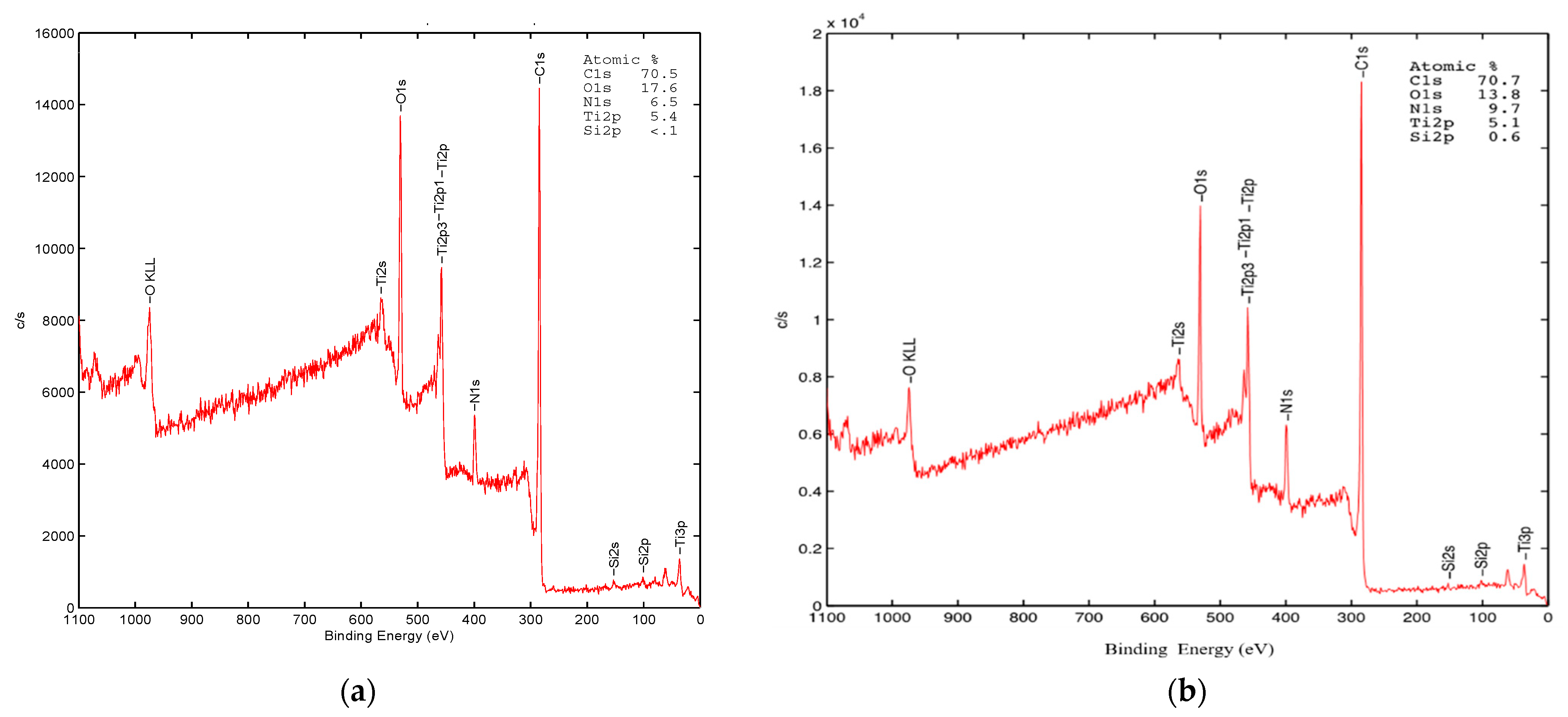
To determine whether the ceramic precursor moved to the perimeter before calcination, two sets of samples were prepared from the medium-concentration recipe, including as-spun fibers and fibers heated at 230 °C for an hour; 230 °C heat treatment was chosen as it is above the glass transition temperature but not high enough to degrade the polymer. This treatment provides energy for diffusion and allows for phase separation if it occurs. As part of the XPS analysis, both of the samples were etched in argon for 1 min, removing roughly 5 nm from the surface, to eliminate surface contamination. Both of the samples appeared to have similar surface compositions of elements, including 70% carbon, 15% oxygen, 7% nitrogen, and 5% titanium. The surface composition of both samples was also quite similar to the recipe, which was 69% carbon, 17% oxygen, 11% nitrogen, and 3% of titanium (Figure 8). The results suggested that phase separation between the polymer and ceramic precursor did not happen during electrospinning or in the initial heating.
3.5. Crystallography
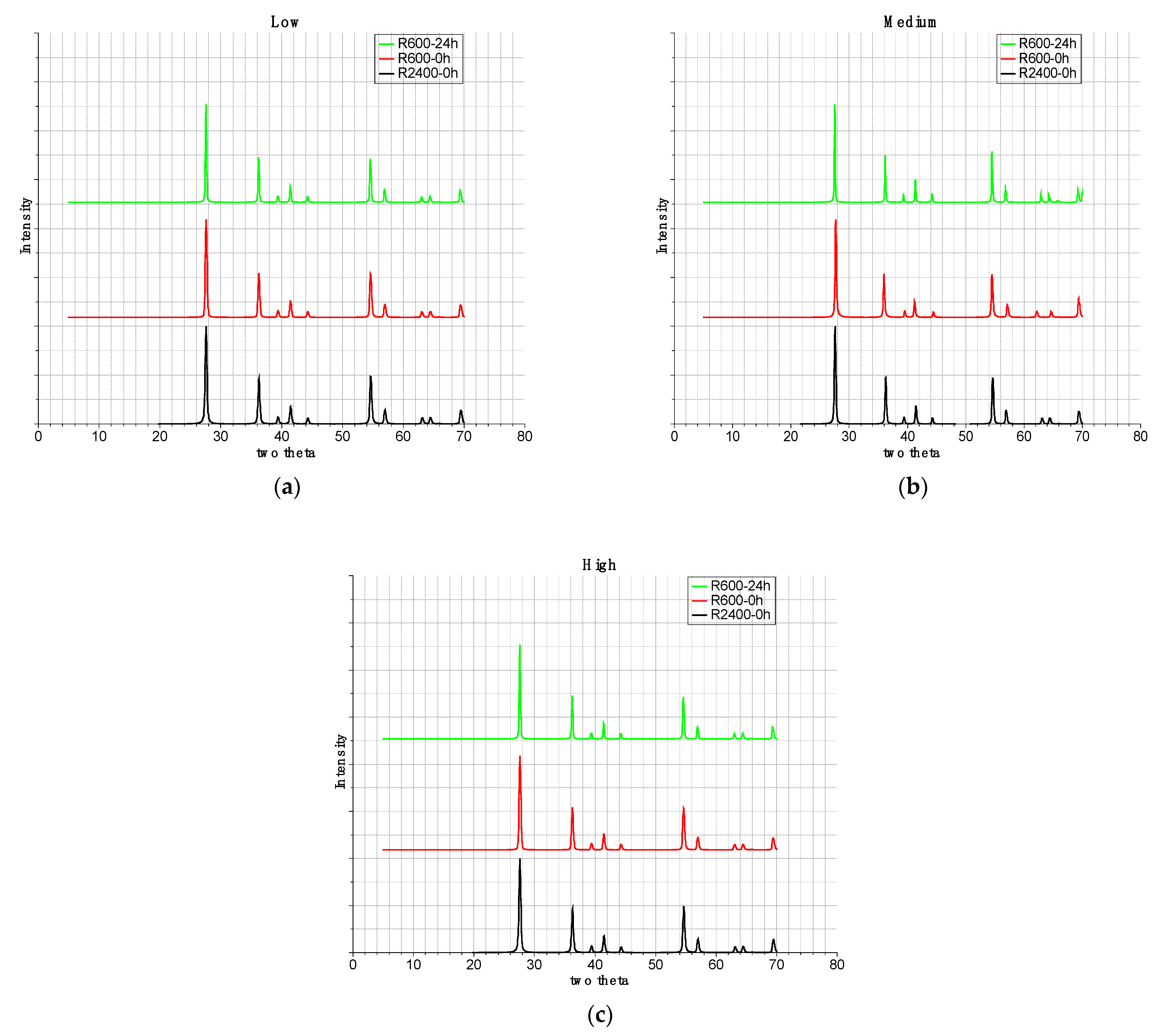
The crystal structures of all samples were identified by powder X-ray diffraction with scanning intervals from 2θ equal 10 to 70 degrees. All the samples were calcined at 950 °C for different soaking times, from zero hours to twenty-four hours. In order to compare the crystallinity of each sample, the intensity of X-ray diffraction was normalized (Figure 9). Only the diffraction peaks of rutile are detected across the three recipes, with 2θ equal to 27.68 (110), 36.32 (101), 41.51 (111), 54.53 (211), 56.84 (220), and 69.23 (301) (JCPDS card no. 21-1276). Moreover, the lattice volumes for all samples were around 60 cubic Angstroms, with lattice parameter a = b ≅ 4.567 and c ≅ 2.947 Angstroms. Transmission electron microscopy images indicate that the particles are single-crystal.
3.6. Proposed Fiber Formation Mechanism
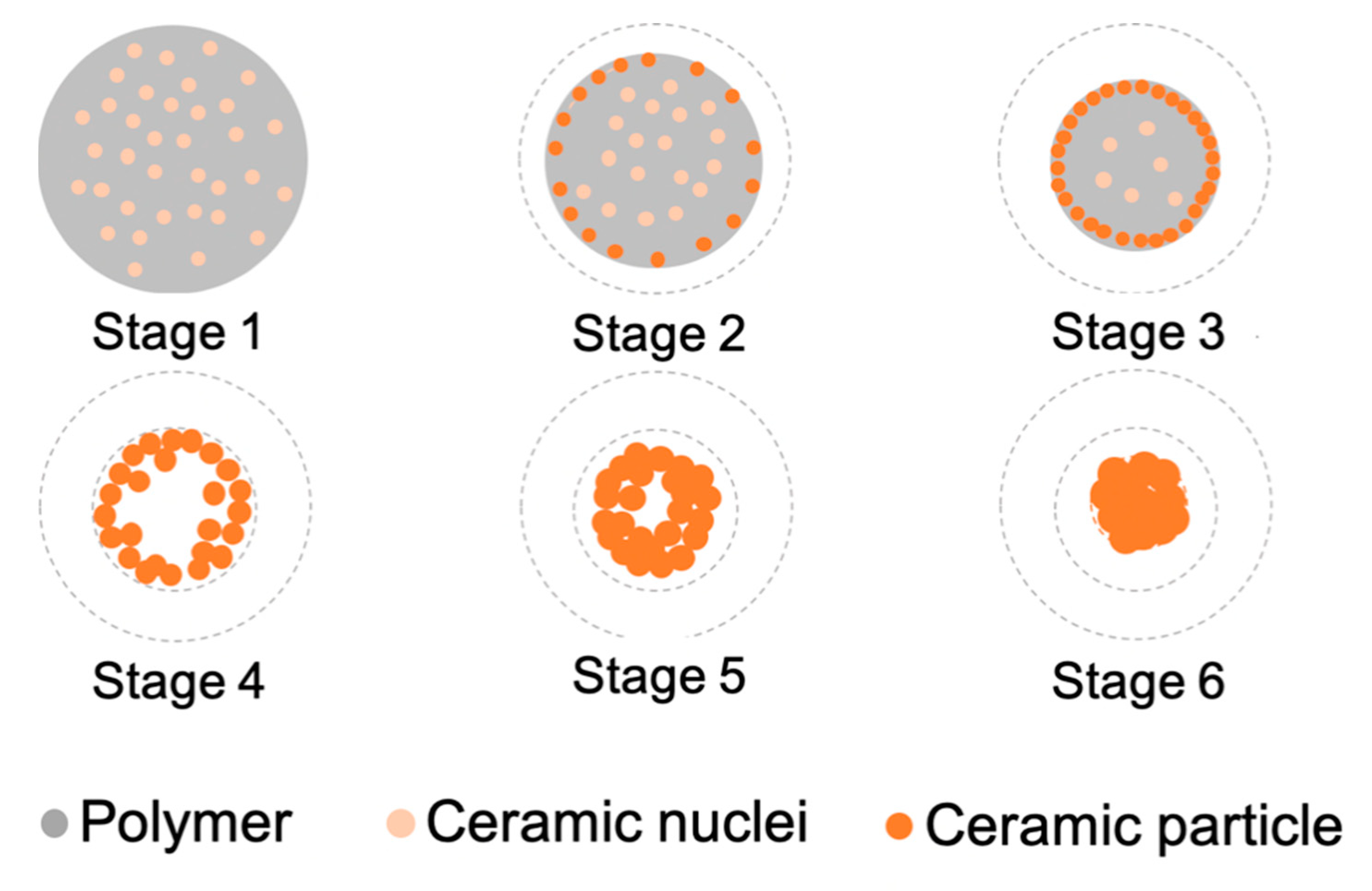
The results indicate that the formation of hollow fibers is controlled by both the initial concentration of the ceramic precursor and the calcination profile. The morphology of the ceramic fiber is believed to develop in three main events, including surface pyrolysis, particle growth, and gasification of polymer (Figure 10). Our XPS results indicate that the ceramic precursor is evenly distributed throughout the fiber prior to any heating and even after mild heating (Stage 1). As the temperature is increased, pyrolysis begins and the as-spun fiber is burned from the outside in, which leads to a reduction in fiber diameter (Stage 2). During this period, the morphology transformation is dominated by surface pyrolysis until a dense solid, ceramic shell forms (Stage 3). The shell is formed with particles that appear to have a minimum diameter of 20 nm. After the shell forms, during Stage 3 and Stage 4, the polymer degradation continues toward the middle of the fiber but the mechanism switches from pyrolysis to thermal gasification. The gasification of the polymer builds up a positive pressure inside the shell. Because of the pressure difference in between the inside and the outside of the shell, the gasified gas tends to bring any remaining ceramic particles outward until they reach the shell. The gas escapes through the shell while particles are filtered. The thickness of the shell then grows outside in until there is no further gasification of polymer (Stage 4). When the calcination temperature reaches 950 °C, grain growth dominates the process. As a result, the hollow fiber contracts and closes up the core of the hollow fiber and leaves a solid fiber (Stage 6).
4. Conclusions
Experimental results have been presented that provide a method for producing rutile titania nanofibers with controlled morphology. Results indicate that the concentration of precursor plays an important role in determining the final morphology. By adjusting the concentration of ceramic precursor, incomplete hollow nanofiber, hollow nanofiber, and solid nanofiber were obtained after calcination of as-spun nanofibers. SEM characterization indicates that the ceramic particle size was restricted by the radius of the fiber. A possible mechanism for the formation of rutile titania nanofibers that includes six stages was proposed. The transformation started from the surface pyrolysis of the polymer that leaves a solid ceramic wall, followed by gasification of the polymer inside the wall, which may result in a hollow or solid morphology. This mechanism can help researchers to develop methods for controlling the synthesis of other ceramic materials from electrospun nanofibers.
Author Contributions
All authors contributed equally to this work. All authors have read and agreed to the published version of the manuscript.
Funding
This research received no external funding.
Data Availability Statement
Not applicable.
Acknowledgments
We would like to acknowledge the technical support from Min Gao at the Advanced Materials and Liquid Crystal Institute, Kent State University and the filtration group led by Professor George Chase, Chemical, Biomolecular, and Corrosion Engineering Department, The University of Akron.
Conflicts of Interest
The authors declare no conflict of interest.
References
- Tseng, T.K.; Lin, Y.S.; Chen, Y.J.; Chu, H. A review of photocatalysts prepared by sol-gel method for VOCs removal. Int. J. Mol. Sci. 2010, 11, 2336–2361. [Google Scholar] [CrossRef]
- Mu Jo, S.; Yeon Song, M.; Rack Ahn, Y.; Rae Park, C.; Young Kim, D. Nanofibril formation of electrospun TiO2 fibers and its application to dye-sensitized solar cells. J. Macromol. Sci. Part A Pure Appl. Chem. 2005, 42, 1529–1540. [Google Scholar] [CrossRef]
- Grätzel, M. Photoelectrochemical cells. Nature 2001, 414, 338–344. [Google Scholar] [CrossRef]
- Zukalová, M.; Kavan, L.; Procházka, J.; Zukal, A.; Yum, J.-H.; Graetzel, M. Nanofibrous TiO2 improving performance of mesoporous TiO2 electrode in dye-sensitized solar cell. J. Nanoparticle Res. 2013, 15, 1640. [Google Scholar] [CrossRef]
- Fujishima, A.; Honda, K. Electrochemical photolysis of water at a semiconductor electrode. Nature 1972, 238, 37–38. [Google Scholar] [CrossRef]
- Kim, I.-D.; Rothschild, A.; Lee, B.H.; Kim, D.Y.; Jo, S.M.; Tuller, H.L. Ultrasensitive chemiresistors based on electrospun TiO2 nanofibers. Nano Lett. 2006, 6, 2009–2013. [Google Scholar] [CrossRef] [PubMed]
- Landau, O.; Rothschild, A. Fibrous TiO2 gas sensors produced by electrospinning. J. Electroceramics 2015, 35, 148–159. [Google Scholar] [CrossRef]
- Landau, O.; Rothschild, A. Microstructure evolution of TiO2 gas sensors produced by electrospinning. Sens. Actuators B Chem. 2012, 171, 118–126. [Google Scholar] [CrossRef]
- Lee, K.; Mazare, A.; Schmuki, P. One-dimensional titanium dioxide nanomaterials: Nanotubes. Chem. Rev. 2014, 114, 9385–9454. [Google Scholar] [CrossRef] [PubMed] [Green Version]
- Wang, X.; Li, Z.; Shi, J.; Yu, Y. One-dimensional titanium dioxide nanomaterials: Nanowires, nanorods, and nanobelts. Chem. Rev. 2014, 114, 9346–9384. [Google Scholar] [CrossRef] [PubMed]
- Lang, L.; Wu, D.; Xu, Z. Controllable Fabrication of TiO2 1D-Nano/Micro Structures: Solid, Hollow, and Tube-in-Tube Fibers by Electrospinning and the Photocatalytic Performance. Chem. A Eur. J. 2012, 18, 10661–10668. [Google Scholar] [CrossRef] [PubMed]
- Byrappa, K.; Adschiri, T. Hydrothermal technology for nanotechnology. Prog. Cryst. Growth Charact. Mater. 2007, 53, 117–166. [Google Scholar] [CrossRef] [Green Version]
- Roy, P.; Berger, S.; Schmuki, P. TiO2 nanotubes: Synthesis and applications. Angew. Chem. Int. Ed. 2011, 50, 2904–2939. [Google Scholar] [CrossRef] [PubMed]
- Liu, N.; Chen, X.; Zhang, J.; Schwank, J.W. A review on TiO2-based nanotubes synthesized via hydrothermal method: Formation mechanism, structure modification, and photocatalytic applications. Catal. Today 2014, 225, 34–51. [Google Scholar] [CrossRef]
- Bavykin, D.V.; Friedrich, J.M.; Walsh, F.C. Protonated titanates and TiO2 nanostructured materials: Synthesis, properties, and applications. Adv. Mater. 2006, 18, 2807–2824. [Google Scholar] [CrossRef]
- Kolmakov, A.; Moskovits, M. Chemical sensing and catalysis by one-dimensional metal-oxide nanostructures. Annu. Rev. Mater. Res. 2004, 34, 151–180. [Google Scholar] [CrossRef] [Green Version]
- Zhai, T.; Yao, J. One-Dimensional Nanostructures: Principles and Applications; Wiley Online Library: Hoboken, NJ, USA, 2013. [Google Scholar]
- Cho, J.S.; Hong, Y.J.; Kang, Y.C. Electrochemical properties of fiber-in-tube-and filled-structured TiO2 nanofiber anode materials for lithium-ion batteries. Chem. A Eur. J. 2015, 21, 11082–11087. [Google Scholar] [CrossRef]
- Li, L.; Peng, S.; Lee, J.K.Y.; Ji, D.; Srinivasan, M.; Ramakrishna, S. Electrospun hollow nanofibers for advanced secondary batteries. Nano Energy 2017, 39, 111–139. [Google Scholar] [CrossRef]
- Xue, J.; Wu, T.; Dai, Y.; Xia, Y. Electrospinning and electrospun nanofibers: Methods, materials, and applications. Chem. Rev. 2019, 119, 5298–5415. [Google Scholar] [CrossRef] [PubMed]
- Wu, H.; Pan, W.; Lin, D.; Li, H. Electrospinning of ceramic nanofibers: Fabrication, assembly and applications. J. Adv. Ceram. 2012, 1, 2–23. [Google Scholar] [CrossRef] [Green Version]
- Ding, B.; Kim, C.K.; Kim, H.Y.; Seo, M.K.; Park, S.J. Titanium dioxide nanofibers prepared by using electrospinning method. Fibers Polym. 2004, 5, 105–109. [Google Scholar] [CrossRef]
- Watthanaarun, J.; Pavarajarn, V.; Supaphol, P. Titanium (IV) oxide nanofibers by combined sol–gel and electrospinning techniques: Preliminary report on effects of preparation conditions and secondary metal dopant. Sci. Technol. Adv. Mater. 2005, 6, 240–245. [Google Scholar] [CrossRef]
- Tang, Z.S.; Bolong, N.; Saad, I.; Ayog, J.L. The Morphology of Electrospun Titanium Dioxide Nanofibers and Its Influencing Factors. In Proceedings of the 3rd International Conference on Civil and Environmental Engineering for Sustainability (IConCEES 2015), Ulysse, France, 1 April 2016. [Google Scholar]
- Park, J.-Y.; Lee, I.-H. Characterization and morphology of prepared titanium dioxide nanofibers by electrospinning. J. Nanosci. Nanotechnol. 2010, 10, 3402–3405. [Google Scholar] [CrossRef] [PubMed]
- Lee, K.; Lee, S. Multifunctionality of poly (vinyl alcohol) nanofiber webs containing titanium dioxide. J. Appl. Polym. Sci. 2012, 124, 4038–4046. [Google Scholar] [CrossRef]
- Zhao, X.; Wang, Y.; Chen, H.; Xu, Y. Revisiting the calcination-induced multi-layer hollowing of electrospun solid fibers. CrystEngComm 2016, 18, 8637–8644. [Google Scholar] [CrossRef]
- Jian, P.-Z.; Chiu, Y.-C.; Sun, H.-S.; Chen, T.-Y.; Chen, W.-C.; Tung, S.-H. Using a single electrospun polymer nanofiber to enhance carrier mobility in organic field-effect transistors toward nonvolatile memory. ACS Appl. Mater. Interfaces 2014, 6, 5506–5515. [Google Scholar] [CrossRef]
- Zhao, C.; Gong, H.; Niu, G.; Wang, F. Electrospun Ca-doped In2O3 nanotubes for ethanol detection with enhanced sensitivity and selectivity. Sens. Actuators B Chem. 2019, 299, 126946. [Google Scholar] [CrossRef]
- Wang, Y.; Li, D.; Ma, Q.; Tian, J.; Song, Y.; Xi, X.; Dong, X.; Yu, W.; Wang, J.; Liu, G. A novel and facile approach to obtain NiO nanowire-in-nanotube structured nanofibers with enhanced photocatalysis. R. Soc. Adv. 2018, 8, 11051–11060. [Google Scholar] [CrossRef] [Green Version]
- Xiang, H.; Long, Y.; Yu, X.; Zhang, X.; Zhao, N.; Xu, J. A novel and facile method to prepare porous hollow CuO and Cu nanofibers based on electrospinning. CrystEngComm 2011, 13, 4856–4860. [Google Scholar] [CrossRef]
- Zhang, Z.; Li, X.; Wang, C.; Wei, L.; Liu, Y.; Shao, C. ZnO hollow nanofibers: Fabrication from facile single capillary electrospinning and applications in gas sensors. J. Phys. Chem. C 2009, 113, 19397–19403. [Google Scholar] [CrossRef]
- Eid, C.; Brioude, A.; Salles, V.; Plenet, J.-C.; Asmar, R.; Monteil, Y.; Khoury, R.; Khoury, A.; Miele, P. Iron-based 1D nanostructures by electrospinning process. Nanotechnology 2010, 21, 125701. [Google Scholar] [CrossRef] [PubMed] [Green Version]
- Cheng, Y.; Zou, B.; Wang, C.; Liu, Y.; Fan, X.; Zhu, L.; Wang, Y.; Ma, H.; Cao, X. Formation mechanism of Fe2O3 hollow fibers by direct annealing of the electrospun composite fibers and their magnetic, electrochemical properties. CrystEngComm 2011, 13, 2863–2870. [Google Scholar] [CrossRef]
- Livage, J.; Henry, M.; Sanchez, C. Sol-gel chemistry of transition metal oxides. Prog. Solid State Chem. 1988, 18, 259–341. [Google Scholar] [CrossRef]
- Silva, C.R.; Airoldi, C. Acid and base catalysts in the hybrid silica sol–gel process. J. Colloid Interface Sci. 1997, 195, 381–387. [Google Scholar] [CrossRef]
- Jaramillo, J.; Garzón, B.A.; Mejía, L.T. Influence of the pH of the Synthesis Using Sol-Gel Method on the Structural and Optical Properties of TiO2. In Proceedings of the 3rd International Meeting for Researchers in Materials and Plasma Technology (IMRMPT) & 1st Symposium on Nanoscience and Nanotechnology, Bucaramanga, Colombia, 4–9 May 2015; p. 12099. [Google Scholar]
- Burgos, M.; Langlet, M. The sol-gel transformation of TIPT coatings: A FTIR study. Thin Solid Film. 1999, 349, 19–23. [Google Scholar] [CrossRef]
Figure 1.
Schematic for particle size measurement.

Figure 2.
FTIR peak information for the (a) raw material, namely TiO2 and PVP, (b) as-spun fiber after calcination. (The number after the M stands for the soaking temperature with unit °C.)
Figure 2.
FTIR peak information for the (a) raw material, namely TiO2 and PVP, (b) as-spun fiber after calcination. (The number after the M stands for the soaking temperature with unit °C.)

Figure 3.
SEM images of fiber samples with low, medium, and high concentrations under different calcination profiles. (a) Low-as-spun, (b) Low-R2400-0h, (c) Low-R600-0h, (d) Low-R600-24h, (e) Medium-as-spun, (f) Medium-R2400-0h, (g) Medium-R600-0h, (h) Medium-R600-24h, (i) High-as-spun, (j) High-R2400-0h, (k) High-R600-0h, and (l) High-R600-24h.


Figure 4.
Measurement of fiber diameter for as-spun fiber and after calcination.

Figure 5.
TEM images of fiber samples with low, medium, and high recipes with 2400 °C/h heating rate without soaking. (R2400-0h). (a,b) Low, (c,d) Medium, and (e,f) High.
Figure 5.
TEM images of fiber samples with low, medium, and high recipes with 2400 °C/h heating rate without soaking. (R2400-0h). (a,b) Low, (c,d) Medium, and (e,f) High.

Figure 6.
Measurement of particle size of as-spun fiber and after calcination.

Figure 7.
Measurement of aspect ratio for as-spun fiber and after calcination.

Figure 8.
XPS spectrum for recipe (a) medium as-spun fiber and (b) after calcined at 230 °C for an hour.
Figure 8.
XPS spectrum for recipe (a) medium as-spun fiber and (b) after calcined at 230 °C for an hour.

Figure 9.
X-ray diffraction with normalized peak intensity of TiO2 fiber samples with formula (a) low, (b) medium, and (c) high.
Figure 9.
X-ray diffraction with normalized peak intensity of TiO2 fiber samples with formula (a) low, (b) medium, and (c) high.

Figure 10.
Overall fiber transformation mechanism.


Table 1.
Recipe of as-spun green fibers with ceramic precursor.
| Formula | TIP/PVP (Mass Ratio) | Solvent Type | As-Spun Fiber Diameter (nm) |
|---|---|---|---|
| Low | 0.05 | Ethanol | 1594 ± 16 |
| Medium | 0.62 | Chloroform/DMF | 1008 ± 59 |
| High | 1.50 | Chloroform/DMF | 877 ± 10 |
Table 2.
Parameters for electrospinning apparatus.
| Formula | Applied Voltage (kV) | Tip-to-Collector Distance (cm) | Pumping Rate (mL/h) |
|---|---|---|---|
| Low | 5 | 5 | 1 |
| Medium | 7 | 7 | 1.5 |
| High | 8 | 10 | 1 |
Table 3.
Calcination procedure for each profile.
| Calcination Profile | Ramping Rate (°C/h) | Soaking Time (h) | Cooling Rate (°C/h) |
|---|---|---|---|
| R2400-0h | 2400 | 0 | 150 |
| R600-0h | 600 | 0 | 150 |
| R600-24h | 600 | 24 | 150 |
Publisher’s Note: MDPI stays neutral with regard to jurisdictional claims in published maps and institutional affiliations. |
© 2021 by the authors. Licensee MDPI, Basel, Switzerland. This article is an open access article distributed under the terms and conditions of the Creative Commons Attribution (CC BY) license (http://creativecommons.org/licenses/by/4.0/).
Share and Cite
MDPI and ACS Style
Kang, C.-S.; Evans, E. Synthesis and Transformation of Hollow Rutile Titania Wires by Single Spinneret Electrospinning with Sol-Gel Chemistry. Fibers 2021, 9, 18. https://0-doi-org.brum.beds.ac.uk/10.3390/fib9030018
AMA Style
Kang C-S, Evans E. Synthesis and Transformation of Hollow Rutile Titania Wires by Single Spinneret Electrospinning with Sol-Gel Chemistry. Fibers. 2021; 9(3):18. https://0-doi-org.brum.beds.ac.uk/10.3390/fib9030018
Chicago/Turabian StyleKang, Chin-Shuo, and Edward Evans. 2021. "Synthesis and Transformation of Hollow Rutile Titania Wires by Single Spinneret Electrospinning with Sol-Gel Chemistry" Fibers 9, no. 3: 18. https://0-doi-org.brum.beds.ac.uk/10.3390/fib9030018
Note that from the first issue of 2016, this journal uses article numbers instead of page numbers. See further details here.