Article

Formation of Polysulfone Hollow Fiber Membranes Using the Systems with Lower Critical Solution Temperature

1
Institute of Physical Organic Chemistry, National Academy of Sciences of Belarus, 13 Surganov Str., 220072 Minsk, Belarus
2
Henan Academy of Sciences, Institute of Chemistry, 56 Hongzhuan Road, Jinshui District, Zhengzhou 450002, China
3
A.V. Topchiev Institute of Petrochemical Synthesis, Russian Academy of Sciences, 29, Leninsky Prospect, 119991 Moscow, Russia
*
Authors to whom correspondence should be addressed.
Submission received: 15 January 2021 / Revised: 18 March 2021 / Accepted: 26 April 2021 / Published: 2 May 2021

Abstract

:
This study deals with the investigation of the phase state of the polymer systems from polysulfone (PSF) with the addition of polyethylene glycol (PEG-400, Mn = 400 g·mol−1) and polyvinylpyrrolidone (PVP K-30, Mn = 40,000 g·mol−1) in N,N-dimethylacetamide (DMA), which feature lower critical solution temperatures (LCSTs). A fragment of the phase state diagram of the system PSF —PEG-400—PVP K-30—DMA was experimentally constructed in the following range of component concentrations: PSF 20–24 wt.%, PEG-400—35–38 wt.% and PVP—0–8 wt.%. It has been established that PVP addition substantially reduces the phase separation temperature down to 50–60 °C. Based on the obtained phase diagrams, a method for preparation of highly permeable hollow fiber membranes from PSF, which involves the processing of the dope solution at a temperature close to the LCST and the temperature of the bore fluid above the LCST, was proposed. Hollow fiber membranes with pure water flux of 1200 L·m−2·h−1 and a sponge-like macrovoid-free structure were obtained via LCST-thermally induced phase separation by free fall spinning technique.

1. Introduction

Membrane separation processes feature the benefits of low energy consumption, high separation performance and eco-friendliness, without the necessity of using chemical reagents compared to traditional methods of water treatment [1]. Polymer hollow fiber membranes have several benefits compared to flat-sheet membranes, such as high surface area-to-volume ratios, good flexibility and easy handling, a self-supporting system (no necessity of using support for membrane formation), relative ease of membrane module production, high packing density per unit volume in a membrane module, the possibility of back flushing and a low area of membrane equipment [2,3,4,5]. The phase inversion is the most commonly applied and is an important method for polymer membrane preparation. According to the driving force that induces the phase separation, two different separation mechanisms take place: thermally induced phase separation (TIPS) and non-solvent induced phase separation (NIPS). In the NIPS method, the polymer solution undergoes phase separation due to the contact to the vapor or liquid (non-solvent). It yields the change in the local composition of the polymer film followed by polymer precipitation [6,7]. NIPS is usually used for polymers which can be dissolved at room temperature. NIPS yields the formation of the dense skin layer and the fingerlike large macrovoids in the membrane matrix, which leads to poor mechanical strength and low membrane permeability [8]. In the TIPS method, a decrease in the temperature of the hot one-phase casting solution leads to the precipitation of a membrane-forming polymer [9]. As the temperature of the cast film decreases, the membrane-forming polymer precipitates, and the phase separation occurs: a polymer-rich phase forms a polymer matrix and a polymer-lean phase forms the pores filled with solvent [10]. The TIPS method is commonly used for preparation of porous membranes for ultrafiltration, microfiltration and membrane desalination from low-soluble semicrystalline or crystalline polymers (polyethylene, polypropylene, polytetrafluorethylene, polyvinylidene fluoride, poly(ethylene chlorotrifluoroethylene), poly(ethylene-co-vinyl alcohol), polyamide, polyvinyl butyral [9,10,11,12]. Three types of membrane structure are known to be formed via TIPS: spinodal decomposition leads to the network membrane structure formation, solid–liquid phase separation results in the spherulite structure with the thicker skin-layer, and liquid–liquid phase separation yields the closed cellular pore structure formation [10]. TIPS features several benefits in comparison with the NIPS method. For instance, it provides a set of tools to easily control membrane structure and crystal morphology, which is beneficial to tailor the membrane hydrophobicity and the possibility of processing low-soluble polymers. Moreover, fewer parameters have to be controlled during membrane preparation via TIPS compared to NIPS and membranes with a higher mechanical strength and a more uniform structure with fewer defects and a narrower pore size distribution can be formed [9,10,11,12].
To combine the benefits of NIPS and TIPS, novel methods of microporous membrane preparation were developed, which involve the phase separation of a polymer solution via temperature change and contact with the non-solvent. These methods include upper critical solution temperature UCST-TIPS, lower critical solution temperature LCST–TIPS (reverse TIPS, RTIPS) [13,14,15,16,17,18,19], nonsolvent thermally induced phase separation (N-TIPS) [20,21,22,23] and thermally assisted NIPS (T-NIPS) [24,25,26].
In the LCST–TIPS, a homogeneous polymer solution featuring LCST is prepared at room temperature and is put in a water coagulation bath at a temperature higher than LCST for membrane preparation. Phase separation is caused by heating up the polymer solution quickly to a LCST. The LCST–TIPS combines a low temperature of polymer solution preparation with fast heat transfer. The driving force which induces phase separation is fast heat transfer. However, the polymer undergoes precipitation also due to the contact with the non-solvent. The membranes obtained via LSCT-TIPS were found to feature a porous selective layer and a bi-continuous structure of membrane matrix, which usually yields a high pure water flux and a high mechanical strength [13,14,15,16,17,18,19].
LCST-TIPS was applied to prepare high flux flat sheet microporous membranes using such systems as polyethersulfone (PES) polyethylene glycol (PEG, Mn = 200 g·mole−1)-N,N-dimethylacetamide (DMA) [13], PES-cellulose acetate (CA)-diethylene glycol (DEG)-DMA [16], PES-DEG-DMA, PES-PEG-200-DMA, PES-PEG-300-DMA, PES-PEG-400-DMA [17]. Hollow fiber membranes via LCST-TIPS were prepared using the polymer systems PES-sulfonated PES-PEG-200-DMA [16], PES-DEG-DMA-TiO2 [14], polysulfone (PSF)- hyperbranched polyesters (HBPEs) based on 2,2-bis(methylol)propionic acid (bis-MPA)-PEG-400-DMA [8].
For instance, hyperbranched polyesters (HBPEs) based on 2,2-bis(methylol)propionic acid (bis-MPA) were used as an hydrophilizing additive and PEG-400 was used as a pore-former to prepare PSF hollow fiber membranes from PSF casting solutions in DMA [8]. It was found that PSF solutions containing 0.5–1.5 wt.% HBE and 33.15–33.76 wt.% PEG-400 feature LCST in the temperature range 47–72 °C. The significant increase of pure water flux of hollow fiber membranes can be achieved when optimal HBPE content in the casting solution was used and the coagulation bath temperature is kept at LCST (300–400 L·m−2·h−1) [8].
Hollow fiber ultrafiltration membranes from polysulfones (PSF, PES) are widely used for surface water purification and wastewater treatment [27]. PSF features several advantages as a membrane material: for instance, high thermal and chemical resistance, mechanical stability, large scale production and commercial availability [28]. However, the hydrophobic nature of PSF yields a low pure water flux and reduces the membrane’s stability to fouling by natural organic matter [29]. To avoid these drawbacks, water soluble hydrophilic polymers and oligomers (polyethylene glycol (PEG) [30,31,32,33,34,35,36,37], polyvinypyrrolidone (PVP) [38,39,40,41] block copolymers of polyethylene glycol and polypropylene glycol [42,43]) are often added to casting solutions for membrane preparation.
PEGs of low molecular weights are commonly used as additives to the casting solutions for membrane preparation for ultrafiltration, microfiltration, nanofiltration, dialysis and reverse osmosis [29,32,33]. PEG additives often act as a pore-former upon membrane preparation via NIPS. Thus, a significant difference in the effect of low molecular weight PEG (200, 400 and 600 g·mol−1) on the structure and performance of membranes obtained from casting solutions PES-N,N-dimethylformamide (DMF)-PEG is revealed [33]. It was shown that the increase in the concentration of PEG with molecular weight of 200 g·mol−1 (PEG-200) in the casting solution from 5 wt.% to 25 wt.% yields the decrease in pure water flux. It was found that when PEG-400 and PEG-600 are used, the relationship is reversed [33]. The influence of PEG molecular weight (400 g·mol−1, 6000 g·mol−1, 20,000 g·mol−1) on the structure and performance of PSF anisotropic membranes, prepared using N-methyl-2-pyrrolidone (NMP) and DMA as solvents, was studied [29,32]. It was reported that when PEG molecular weight increases, the average pore size of the selective layer decreases and membrane porosity increases. It yields the increase in membrane pure water flux. The influence of PEG molecular weight in the range of 600–150,000 g·mol−1 on the separation performance and structure of hollow fiber microfiltration membranes prepared from the PSF-NMP-PEG dope solutions via the combination of NIPS and evaporation induced phase separation was studied [35]. It was found that upon the increase of PEG molecular weight from 600 g·mol−1 to 150,000 g·mol−1, pure water flux increases from 160 to 8260 L·m−2·h−1, which is due to the increase in the pore size of the membrane selective layer [35].
PVP is one of the commonly used additives for hydrophilization of both flat sheet and hollow fiber membranes. PVP is well compatible with many membrane-forming polymers (polysulfones, polyacrylonitrile, fluorinated polymers, polyamides) and features high water solubility [38,39,40,41]. The main function of PVP is hydrophilization of membrane material, adjustment of casting solution viscosity and formation of more uniform and mechanically stable membrane structure [38,39,40,41]. The influence of the addition of PVP and lithium chloride to the PSF casting solution on the structure and performance of flat sheet membranes was studied in [41]. It was found that PVP introduction to the casting solution yields the increase of porosity and membrane permeability [41]. PVP and PEG are often added to the casting solution simultaneously. The formation of PSF ultrafiltration membranes from the casting solutions with the addition of PEG with Mn = 4000 g·mol−1 (PEG-4000) and PVP with Mn = 40,000 g·mol−1 (PVP K-30) was studied [44]. PVP was revealed to increase the casting solution viscosity, which results in a decrease in the rate of phase separation. It was found that the addition of PEG-4000 to the PSF casting solutions in DMA yields the slight decrease of the water contact angle of the membrane selective layer from 70° (for reference PSF membrane) to 63–65° (for PSF-PEG-4000 membrane). Meanwhile, it was shown that the introduction of 1–2 wt.% of PVP to the casting solution results in the decrease of water contact angle from 70° (for reference PSF membrane) to 45° for modified membrane [44].
The aim of this research was to study the phase state of the polymer systems from PSF with LCST, which offers a perspective for polymer membrane preparation and to develop the LCST–TIPS method for highly permeable hollow fiber membrane formation. As such a system is based on common and available polymer additives, the properties of four-component solutions PSF-PEG-400-PVP K-30-DMA were studied. This polymer solution is recognized to be a perspective system for preparation of highly permeable hollow fiber membranes [17]. Data on the change in the phase state of PSF solutions depending on concentration and temperature are of practical importance for the development of a technological process for hollow fiber membrane formation, since they allow directionally varying the rate of phase inversion and the structure of the hollow fiber membranes obtained. The idea of this study is that combining NIPS and LCST–TIPS allows changing the membrane structure to prepare a highly permeable membrane. For the first time, the LCST-TIPS technique was applied for hollow fiber membrane preparation using the polymer system PSF-PEG-400-PVP K30-DMA by free fall spinning. It is worth noting that only a few works have been reported on the application of LCST-TIPS for hollow fiber membrane preparation and the polymer system PSF-PEG-400-PVP K30-DMA has not been applied yet for hollow fiber membrane formation via LCST-TIPS [8,14].

2. Materials and Methods

2.1. Materials

Polysulfone (PSF, Ultrason S 6010, Mn = 55,000 g∙mol−1, BASF, Ludwigshafen, Germany), polyethylene glycol (PEG-400, Mn = 400 g∙mol−1, BASF, Ludwigshafen, Germany), polyvinylpyrrolidone with molecular weight of 10,000, 40,000, 1,300,000 g∙mol−1 (PVP K-15, PVP K-30, PVP K-90 respectively, Fluka, Germany) and N,N-dimethylacetamide (DMA, BASF, Ludwigshafen, Germany) were used as membrane forming polymer, additives and solvent, respectively.

2.2. Preparation of Polymer Solutions

For polymer solution preparation 20–24 wt.% PSF, 30–40 wt.% PEG-400, 0–8 wt.% PVP (PVP K-15, PVP K-30, PVP K-90) and DMA were stirred for 5 h at 120 °C using an overhead stirrer at 800 rpm. Preparation of the dope solutions for hollow fiber membranes was performed in a laboratory stainless steel thermostated reactor at T = 120 °C. Stirring duration was 5 h. The prepared solution was filtered using a stainless steel wire mesh with a mesh width of 5 μm and degassed for 12 h.

2.3. Cloud Point Measurements

Cloud point of PSF solutions with PEG-400, PVP K-15, PVP K-30 and PVP K-90 additives in DMA was fixed by sight after keeping 5 mL of the solution in the oven for 120 min at a given temperature. The temperature of the oven was changed from 25 °C up to 140 °C with the step of 5 °C.

2.4. PSF Solution Viscosity

Viscosity (η) of PSF solutions with PEG-400, PVP K-15, PVP K-30 and PVP K-90 additives in DMA at T = 25 °C was measured by a Brookfield DV III Ultra instrument.

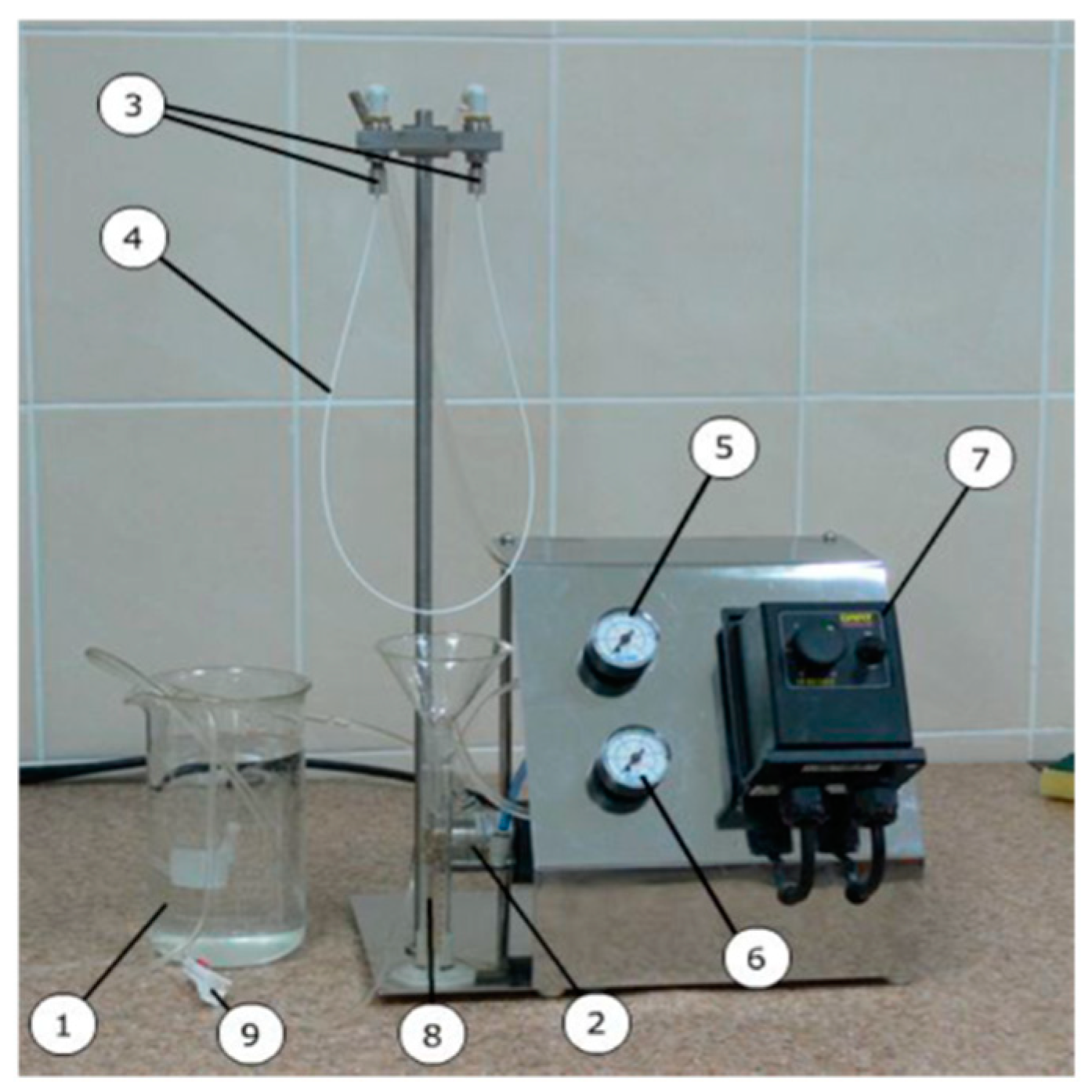
2.5. Hollow Fiber Membrane Formation

PSF hollow fiber membranes were prepared by a free fall spinning method using distilled water as a bore fluid, which was described in detail previously [28,31]. There is no take-up bobbin in the system; thus, the fiber is formed due to gravitational force by free fall spinning. The main features of the free fall spinning technique are (1) phase separation of the dope solution is usually carried out in air only upon contact with the bore fluid; in the coagulation bath, the hollow fiber membrane is washed of the residual solvent; (2) the hollow fiber structure is almost completely formed in the air gap during the passage of the fiber from the spinneret to the coagulation bath; (3) the formation of the hollow fiber membrane occurs under the action of gravity and the “driving” force of the process is determined by the feed rates of the polymer solution and the bore fluid and by the air gap length [28].
The dope solution and bore fluid are supplied to the spinneret by compressed air and controlled by a pressure gauge. The conditions of hollow fiber membrane formation are listed in Table 1. The as-prepared hollow fiber membranes were washed from the residual solvent for 24 h, impregnated with an aqueous glycerol solution to prevent capillary contraction of the pores and was dried at ambient temperature.

2.6. Measurement of Pure Water Flux of Hollow Fiber Membranes

Hollow fiber membrane pure water flux (PWF) was determined at an average transmembrane pressure of 1.0 bar. PWF characterises membrane permeability in ultrafiltration. For individual hollow fiber membranes, the PWF (J, L m2 h1) was measured using a custom-made filtration system operating in the cross-flow mode (Figure 1) [31]. This system includes a gear pump (DGS.68PPT type, Tuthill, Burr Ridge, IL, USA), and a flow-through cell composed of inlet and outlet capillaries. The 0.6 m long sample of the hollow fiber membrane was fixed on the tapered capillaries with special clamps. The pressure at the inlet and outlet capillaries was 1.1 and 0.9 bar, respectively. The volumetric feed rate of the solution supplied to the hollow fiber membrane was 4.5–4.8 L h–1. The pressure was monitored with a manometer.
The pure water flux for hollow fiber membranes was calculated according to the Equation (1):
J = V ( S t ) = V ( t π d l )
where V is the volume of liquid (m3) passed through the membrane during time t (s); d is the inner diameter of the hollow fiber (m); l is the length of hollow fiber (m); and S is the area of the hollow fiber membrane (m2).
For measurement of PWF, five different membrane samples were tested and the average value was calculated. The relative error was found to be less than 5%.

2.7. Study of Hollow Fiber Membrane Structure

The investigation of the morphological structure of the hollow fiber membranes was carried out using an LEO 1420 scanning electron microscope (LEO Electron Microscopy Inc., Thornwood, NY, USA). Cleaved samples were prepared via cryogenic fracture in liquid nitrogen followed by gold layer sputtering (DSR1, Vaccoat, UK).

2.8. Contact Angle Measurements

Water contact angle (θ, °) of the selective layer of hollow fiber membranes was measured by the captive bubble method using the LK-1 goniometer (Open Science, Krasnogorsk, Russia). The hollow fiber membrane was carefully cut along its axis, unrolled and fastened in the measuring cell by the outer surface with the inner skin layer or outer layer down. The layer under study was directed to the 0.02 M NaCl solution. An air bubble with a volume of 0.02 cm3 was carefully applied to the membrane surface using a microsyringe. When the air bubble was moving from the bottom to the surface of the cuvette it attached spontaneously to the membrane surface (selective layer). The images of the system “membrane-air bubble” in water were taken by a camera at magnification in 24 times and were processed by image analysis software DropShape.

2.9. Determination of Hollow Fiber Burst Pressure

Hollow fiber burst pressure is a pressure at which the hollow fiber membrane loses its integrity and breaks. To determine hollow fiber burst pressure, a sample of hollow fiber membrane with the length of 1 m is fixed on a capillary connected to a gas balloon with nitrogen or a compressor equipped with a manometer. The hollow fiber membrane sample is blocked from the other side using epoxy glue in such a way that it does not allow the gas to pass. The hollow fiber membrane is placed in the water. The pressure is increased until the hollow fiber membrane breaks. During the increase of the pressure the occurrence of bubbles of gas in water is observed. The presence of gas bubbles in water indicates the micro defects of the selective layer. At least ten samples of the hollow fiber membrane were tested.

3. Results

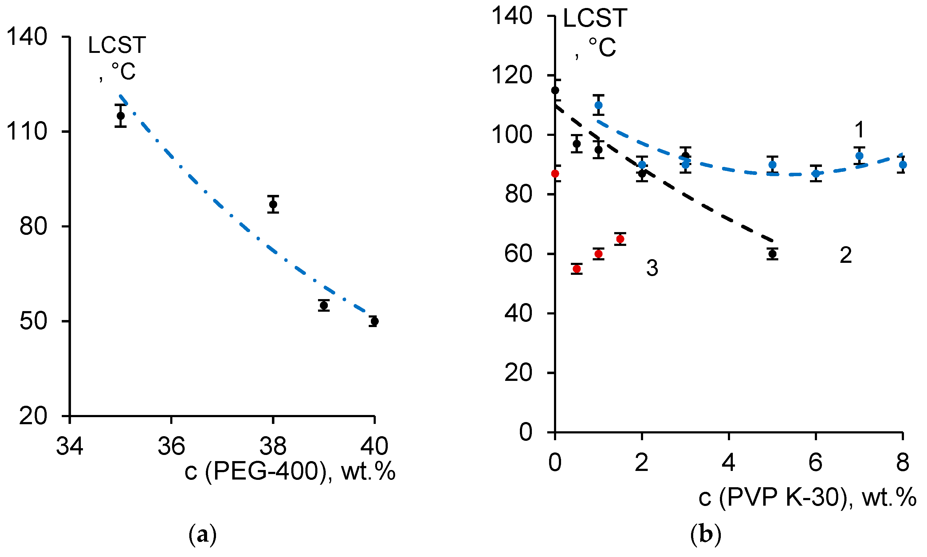
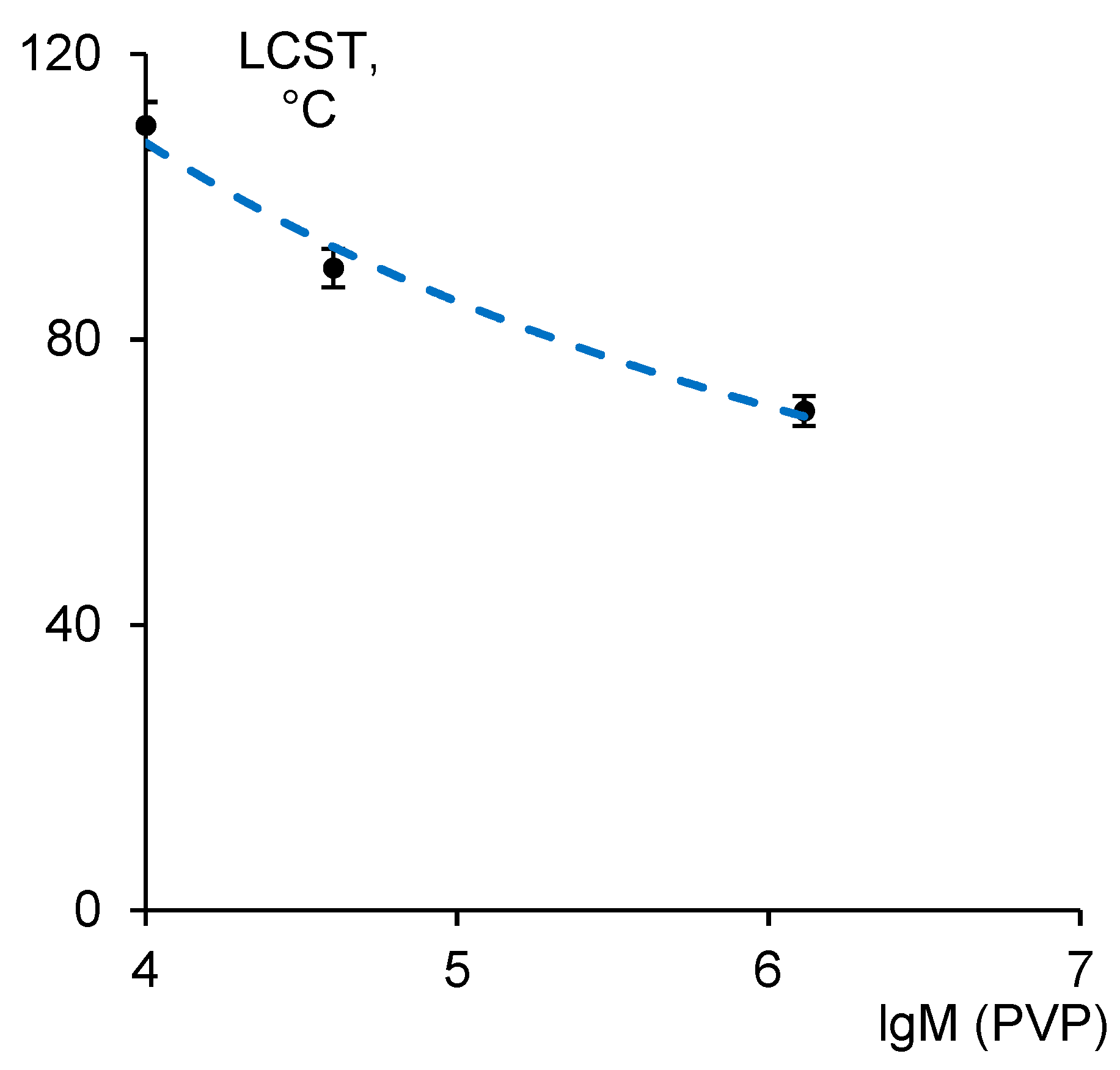
3.1. Investigation of the Phase State of PSF-PEG-400-PVP-DMA Solutions

The phase state and viscosity of PSF solutions in DMA with the addition of PEG-400 has been studied previously [30]. It was found that for 20 wt.% PSF solutions with the PEG-400 content less than 30 wt.%, low critical solution temperature (LCST) is higher than the boiling point of the solvent (Tb = 164 °C) and afterwards cannot be detected [30]. It was found that when PEG-400 concentration in 20 wt.% PSF solution in DMA increases from 30 wt.% to 35 wt.%, LCST decreases down to 115 °C (Figure 2a). High LCST of the solutions with the composition of 20 wt.% PSF 30–35 wt.% PEG-400 in DMA limit their application as dope solutions for membrane preparation via LCST-TIPS. It was shown that further increase in PEG-400 concentration in 20 wt.%PSF solutions in DMA from 35 wt.% up to 40 wt.% yields a substantial decrease in LCST from 115 °C down to 50 °C (Figure 2a).
It was revealed that additional introduction of PVP K-30 into the casting solutions containing 30–38 wt.% PEG-400 can significantly reduce the phase separation temperature (Figure 2b), while the effect is mainly determined by the concentration of PVP K-30. Thus, it was revealed that polymer systems with a composition of 20 wt.% PSF 35 wt.% PEG-400 with a PVP K-30 concentration above 5 wt.% at room temperature are two-phase systems due to liquid–liquid phase separation. It was found that in 20 wt.% PSF 38 wt.% PEG-400 solution in DMA the threshold PVP K-30 concentration, at which it is possible to obtain one-phase solutions at room temperature is 1.5 wt.% (Figure 2b).
It was revealed that phase separation temperature and viscosity of the polymer system PSF-PEG-400-PVP-DMA significantly depends on the PVP molecular weight. It was shown that upon the increase of PVP K-30 molecular weight from 10,000 g·mol−1 (PVP K15) to 1,300,000 g·mol−1 (PVP K90), the phase separation temperature decreases from 110 °C down to 70 °C and viscosity increases from 17.6 Pa·s for PVP K15 to 19.5 Pa·s for PVP K30 to 23.0 Pa·s for PVP K90 (Figure 3). The decrease in LCST with the increase in PVP molecular weight is due to the decrease in compatibility of PSF and the high molecular weight PVP in the solution, which yields the decrease of thermodynamic stability of the solution. It leads to the narrowing of the miscibility gap on the phase state diagram.

3.2. Hollow Fiber Membrane Formation

According to the dependencies of the LCST of the PSF solutions on the concentrations of the components (PEG-400 and PVP), the dope solution compositions for hollow fiber membrane formation were selected (Table 2). The casting solution compositions and conditions for membrane formation are presented in Table 2. It is possible to obtain a PSF-DMA-PVP-PEG-400 system with quite a low LCST, which can be easily attained in the experimental conditions using a common hollow fiber membrane formation set-up. It provides a fundamentally new possibility for processing dope solutions at the temperature region in the vicinity of phase transition temperature. There are two possible approaches for hollow fiber membrane formation: (1) application of the bore fluid at the temperature near the LCST or higher than LCST and dope solution at the room temperature and (2) the increase of the dope solution processing temperature up to the region near LCST. In this case, at the temperature higher than LCST, the process of phase separation of the dope solution due to temperature change will be superimposed on the process of phase separation of the casting solution upon contact with the non-solvent (coagulant). A combination of the phase separation due to the temperature change (TIPS) and phase separation due to the contact with the non-solvent (coagulant) in the NIPS process is expected to yield the significant change in membrane structure and performance.
At the first step of the approach, assuming the application of the dope solution at room temperature and bore fluid (water), an elevated temperature higher than LCST was implemented for hollow fiber membrane formation (Table 2, dope solution compositions A and B). It was found that the increase in the temperature of the bore fluid (distilled water) in NIPS results in the increase in pure water flux 1.4–1.5 times, which is attributed to the increase in the rate of phase inversion when the bore fluid temperature is increased. The increase in the phase inversion rate is due to approaching the casting solution to the limit of the component compatibility.
To obtain the membranes with the high porosity of the membrane selective layer, the second approach was applied, which implies the heating of the dope solution up to a temperature close to the LCST and the increase in the temperature of the bore fluid higher than LCST (Table 2, dope solution composition C). The increase in the PSF concentration allows a decrease in the LCST down to 50 °C. In this case, the increase in the bore fluid temperature yields the increase in the pure water flux up to 1200 L·m−2·h−1. According to the data presented in Table 2, the substantial increase in the hollow fiber membrane pure water flux occurs when bore fluid temperature is much higher than the LCST of the dope solution (Tbore fluid = 70–80 °C). This is due to the fact that when the dope solution and the bore fluid contact in the spinneret, the temperature of the bore fluid decreases due to the heat exchange between the colder dope solution and the metal spinneret. Thus, at the moment of the contact of the dope solution and the bore fluid, the temperature of the bore fluid is lower compared to the initial temperature of the bore fluid in the thermostated feed tank and in the pipes of the spinning set-up.
Thus, upon the implementation of the first approach when the dope solution is used at the room temperature and bore fluid (water)—at elevated temperature higher than LCST the better increase of membrane permeability is achieved when the system with lower LCST (dope solution composition B) is used. However, the better effect has the implementation of the second approach when dope solution is used at elevated temperature and bore fluid—at the temperature which is much higher than LSCT.

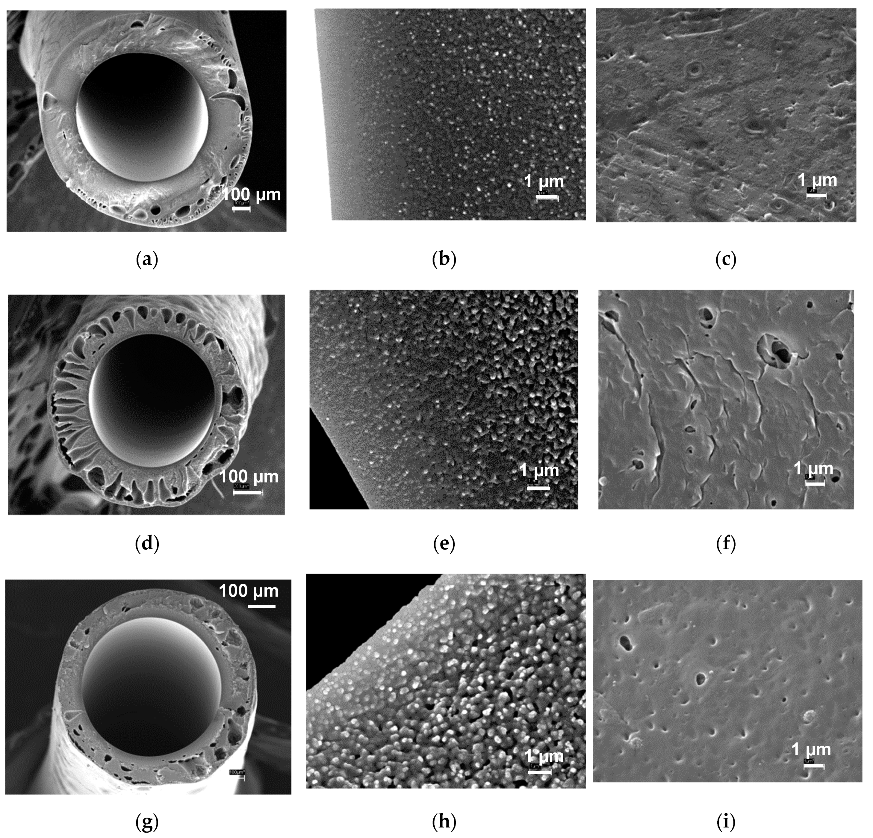
3.3. Hollow Fiber Membrane Structure Studies

The membrane structure was studied using scanning electron microscopy. The structure of the obtained membranes is presented in Figure 4. It was shown that hollow fiber membrane obtained from dope solution A features quite a dense macrovoid-free structure. The pores of the smooth selective layer located on the inner surface of the fiber are not visible at the magnification used (×20,000). The structure of the selective layer is dense; upon the transition from the lumen to the outer surface of the fiber polymer globules appear as structural elements, which form the structure of interconnected pores. However, the structure of the membrane in the vicinity of the selective layer features low porosity. It was shown that the outer surface of the hollow fiber membrane is also dense and has a low quantity of visible pores. This is due to the fact that the structure of the membrane does not have enough time to complete the formation during the passage through the air gap, and its final formation occurs in the coagulation bath. When the dope solution with a lower phase transition temperature (55 °C) and higher viscosity (54.5 Pa·s) is used (dope solution composition B), large macrovoids were revealed to appear in the membrane matrix. It was found that the structural elements (polymer globules) of the membrane selective layer become bigger and more visible at the magnification used (×20,000). They form the network of interconnected pores in the vicinity of the selective layer (Figure 4e). The outer membrane surface becomes more porous and rougher and large pores appeared (Figure 4f). It yields the increase of membrane porosity, leading to the high pure water flux of the membrane (Table 2). Upon the transition to hollow fiber membranes obtained from composition C, further enlargement of the structural elements of the selective layer occurs. Globular formations become clearly distinguishable, the size of which gradually increases with distance from the inner channel of the fiber to the periphery (Figure 4h). Pores of a bigger size appear closer to the selective layer compared to hollow fiber membranes A and B (Figure 4b,e,h). The outer surface of the fiber is also developed and has well-defined pores (Figure 4i).
It was found that the water contact angle of the selective layer of the developed membranes was 45 ± 2 °C. The decrease in water contact angle compared to the contact angle of polysulfone (70°) is due to the addition of 0.75–1.0 wt.% PVP to the dope solution and is consistent with the data reported in the literature [44]. It was revealed that the developed hollow fibers are mechanically robust and defect-free: hollow fiber burst pressure was found to be more than 10 bar. No micro defects were detected upon the increase of pressure to 10 bar according to the procedure described in Section 2.9.

4. Conclusions

The fragments of the phase diagrams of the systems PSF-PEG-400-PVP K-30-DMA are obtained in the following concentration range of the components: 20–24 wt.% PSF, 35–38 wt.% PEG-400, 0–8 wt.% PVP K-30. It was found that the studied systems feature a lower critical solution temperature (LSCT). The addition of PVP K-30 yields the decrease in the critical solution temperature down to 50–60 °C. According to the phase diagrams obtained, a method of preparation of highly permeable PSF hollow fiber membranes is proposed, which implies the processing of the dope solution at the temperature close to LCST and application of a bore fluid temperature higher than LCST. It was shown that the combination of the non-solvent-induced phase separation and temperature-induced phase separation upon hollow fiber membrane preparation allows significant change in the structure and permeability in the hollow fiber membranes. The developed high flux hollow fiber membranes can be applied for water and wastewater treatment.

Author Contributions

Conceptualization, T.V.P. and A.V.B.; methodology, V.V.V., L.Z.; validation, T.V.P., W.H., Z.H.; formal analysis, A.V.B. and T.V.P.; investigation, T.V.P., W.H., and Z.H.; writing—original draft preparation, T.V.P. and A.V.B.; writing—review and editing, V.V.V., and L.Z.; visualization, W.H., Z.H.; supervision, A.V.B. All authors have read and agreed to the published version of the manuscript.

Funding

This research received no external funding.

Institutional Review Board Statement

Not applicable.

Informed Consent Statement

Not applicable.

Data Availability Statement

Not applicable.

Conflicts of Interest

The authors declare no conflict of interest.

References

  1. Werber, J.R.; Osuji, C.O.; Elimelech, M. Materials for next-generation desalination and water purification membranes. Nat. Rev. Mater. 2016, 1, 1–15. [Google Scholar] [CrossRef]
  2. Peng, N.; Widjojo, N.; Sukitpaneenit, P.; Teoh, M.M.; Lipscomb, G.G.; Chung, T.S.; Lai, J.Y. Evolution of polymeric hollow fibers as sustainable technologies: Past, present, and future. Prog. Polym. Sci. 2016, 37, 1401–1424. [Google Scholar] [CrossRef]
  3. Bazhenov, S.D.; Bildyukevich, A.V.; Volkov, A.V. Gas-Liquid Hollow Fiber Membrane Contactors for Different Applications. Fibers 2018, 6, 76. [Google Scholar] [CrossRef] [Green Version]
  4. Kirsch, V.A.; Bazhenov, S.D. Numerical simulation of solute removal from a cross-flow past a row of parallel hollow-fiber membranes. Sep. Purif. Technol. 2020, 242, 116834. [Google Scholar] [CrossRef]
  5. Kirsch, V.A.; Bazhenov, S.D. Towards simulation of gas separation modules based on hollow fiber membranes. J. Phys. Conf. Ser. 2020, 1696, 012041. [Google Scholar] [CrossRef]
  6. Ren, J.; Wang, R. Chapter 2: Preparation of Polymeric Membranes. In Membrane and Desalination Technologies Handbook of Environmental Engineering; Wang, L.K., Chen, J.P., Hung, Y.T., Shammas, N.K., Eds.; Humana Press: Totowa, NJ, USA, 2011; Volume 13. [Google Scholar] [CrossRef]
  7. Ulbricht, M. Advanced functional polymer membranes. Polymer 2006, 47, 2217–2262. [Google Scholar] [CrossRef] [Green Version]
  8. Zhao, L.-B.; Liu, M.; Xu, Z.-L.; Wei, Y.-M.; Xu, M.-X. PSF hollow fiber membrane fabricated from PSF–HBPE–PEG400–DMAc dope solutions via reverse thermally induced phase separation (RTIPS) process. Chem. Eng. Sci. 2015, 137, 131–139. [Google Scholar] [CrossRef]
  9. Liu, M.; Xu, Z.L.; Chen, D.G.; Wei, Y.M. Preparation and characterization of microporous PVDF membrane by thermally induced phase separation from a ternary polymer/solvent/non-solvent system. Desalin. Water Treat. 2010, 17, 183–192. [Google Scholar] [CrossRef] [Green Version]
  10. Xiang, S.; Guo, Z.; Wang, Y.; Liu, H.; Zhang, J.; Cui, Z.; Wang, H.; Li, J. The microstructure regulation, strengthening, toughening and hydrophilicity of polyamide6 in fabricating poly (vinylidene fluoride)-based flat membrane via the thermally induced phase separation technique. Eur. Polym. J. 2020, 126, 109568–109580. [Google Scholar] [CrossRef]
  11. Zuo, J.H.; Li, Z.K.; Wei, C.; Yan, X.; Chen, Y.; Lang, W.Z. Fine tuning the pore size and permeation performances of thermally induced phase separation (TIPS) -prepared PVDF membranes with saline water as quenching bath. J. Membr. Sci. 2019, 577, 79–90. [Google Scholar] [CrossRef]
  12. Fang, C.; Liu, W.; Zhang, P.; Rajabzadeh, S.; Kato, N.; Sasaki, Y.; Shon, H.K.; Matsuyama, H. Hollow fiber membranes with hierarchical spherulite surface structure developed by thermally induced phase separation using triple-orifice spinneret for membrane distillation. J. Membr. Sci. 2021, 618, 118586–118598. [Google Scholar] [CrossRef]
  13. Liu, M.; Wei, Y.-M.; Xu, Z.-L.; Guo, R.-Q.; Zhao, L.-B. Preparation and characterization of polyethersulfone microporous membrane via thermally induced phase separation with low critical solution temperature system. J. Membr. Sci. 2013, 437, 169–178. [Google Scholar] [CrossRef]
  14. Liu, S.H.; Liu, M.; Xu, Z.L.; Wei, Y.M.; Guo, X. A novel PES-TiO2 hollow fiber hybrid membrane prepared via sol-gel process assisted reverse thermally induced phase separation (RTIPS) method. J. Membr. Sci. 2017, 528, 303–315. [Google Scholar] [CrossRef]
  15. Tang, Y.; He, Y.; Wang, X. Investigation on the membrane formation process of polymer–diluent system via thermally induced phase separation accompanied with mass transfer across the interface: Dissipative particle dynamics simulation and its experimental verification. J. Membr. Sci. 2015, 474, 196–206. [Google Scholar] [CrossRef]
  16. Liu, S.H.; Xu, Z.L.; Liu, M.; Wei, Y.M.; Guo, F. Preparation and Characterization of PES/CA Microporous Membranes via Reverse Thermally Induced Phase Separation Process. Polym. Eng. Sci. 2017, 1–12. [Google Scholar] [CrossRef]
  17. Liu, M.; Liu, S.H.; Skov, A.L.; Xu, Z.L. Estimation of phase separation temperatures for polyethersulfone/solvent/non-solvent systems in RTIPS and membrane properties. J. Membr. Sci. 2018, 556, 329–341. [Google Scholar] [CrossRef] [Green Version]
  18. Liu, M.; Skov, A.L.; Liu, S.H.; Yu, L.Y.; Xu, Z.L. A Facile Way to Prepare Hydrophilic Homogeneous PES Hollow Fiber Membrane via Non-Solvent Assisted Reverse Thermally Induced Phase Separation (RTIPS) Method. Polymers 2019, 11, 269. [Google Scholar] [CrossRef] [Green Version]
  19. Liu, S.H.; Liu, M.; Xu, Z.L.; Wei, Y.M. A polyethersulfone–bisphenol sulfuric acid hollow fiber ultrafiltration membrane fabricated by a reverse thermally induced phase separation process. RSC Adv. 2018, 8, 7800–7809. [Google Scholar] [CrossRef] [Green Version]
  20. Jung, J.T.; Kim, J.F.; Wang, H.H.; di Nicolo, E.; Drioli, E.; Lee, Y.M. Understanding the non-solvent induced phase separation (NIPS) effect during the fabrication of microporous PVDF membranes via thermally induced phase separation (TIPS). J. Membr. Sci. 2016, 514, 250–263. [Google Scholar] [CrossRef]
  21. Jung, J.T.; Wang, H.H.; Kim, J.F.; Lee, J.; Kim, J.S.; Drioli, E.; Lee, Y.M. Tailoring nonsolvent-thermally induced phase separation (N-TIPS) effect using triple spinneret to fabricate high performance PVDF hollow fiber membranes. J. Membr. Sci. 2018, 559, 117–126. [Google Scholar] [CrossRef]
  22. Xiao, T.; Wang, P.; Yang, X.; Cai, X.; Lu, J. Fabrication and characterization of novel asymmetric polyvinylidene fluoride (PVDF) membranes by the nonsolvent thermally induced phase separation (NTIPS) method for membrane distillation applications. J. Membr. Sci. 2015, 489, 160–174. [Google Scholar] [CrossRef]
  23. Gao, J.; Chung, T.S. Membranes made from nonsolvent-thermally induced phase separation (N-TIPS) for decellularization of blood in dry plasma spot (DPS) applications. Chem. Eng. Sci. 2021, 229, 116010–116024. [Google Scholar] [CrossRef]
  24. Cho, Y.H.; Kim, S.D.; Kim, J.F.; Choi, H.; Kim, Y.; Nam, S.E.; Park, Y.I.; Park, H. Tailoring the porous structure of hollow fiber membranes for osmotic power generation applications via thermally assisted nonsolvent induced phase separation. J. Membr. Sci. 2019, 579, 329–341. [Google Scholar] [CrossRef]
  25. Plisko, T.V.; Bildyukevich, A.V.; Karslyan, Y.A.; Ovcharova, A.A.; Volkov, V.V. Development of high flux ultrafiltration polyphenylsulfone membranes applying the systems with upper and lower critical solution temperatures: Effect of polyethylene glycol molecular weight and coagulation bath temperature. J. Membr. Sci. 2018, 565, 266–280. [Google Scholar] [CrossRef]
  26. Bildyukevich, A.V.; Plisko, T.V.; Isaichykova, Y.A.; Ovcharova, A.A. Preparation of High-Flux Ultrafiltration Polyphenylsulfone Membranes. Pet. Chem. 2018, 58, 747–759. [Google Scholar] [CrossRef]
  27. Mamah, S.C.; Goh, P.S.; Ismail, A.F.; Suzaimi, N.D.; Yogarathinam, L.T.; Raji, Y.O.; El-badawy, T.H. Recent development in modification of polysulfone membrane for water treatment application. J. Water Process. Eng. 2021. [Google Scholar] [CrossRef]
  28. Bildyukevich, A.V.; Plisko, T.V.; Usosky, V.V. The Formation of Polysulfone Hollow Fiber Membranes by the Free Fall Spinning Method. Pet. Chem. 2016, 56, 379–400. [Google Scholar] [CrossRef]
  29. Yunos, M.Z.; Harun, Z.; Basri, H.; Ismail, A.F. Studies on fouling by natural organic matter (NOM) on polysulfone membranes: Effect of polyethylene glycol (PEG). Desalination 2014, 333, 36–44. [Google Scholar] [CrossRef] [Green Version]
  30. Fen‘ko, L.A.; Bil‘dyukevich, A.V. Phase State of the Polysulfone–Poly(ethylene glycol)– Dimethylacetamide System. Polym. Sci. Ser. A. Polym. Phys. 2013, 55, 75–81. [Google Scholar] [CrossRef]
  31. Plisko, T.V.; Bildyukevich, A.V.; Usosky, V.V.; Volkov, V.V. Influence of the concentration and molecular weight of polyethylene glycol on the structure and permeability of polysulfone hollow fiber membranes. Pet. Chem. 2016, 56, 321–329. [Google Scholar] [CrossRef]
  32. Wu, Q.Y.; Liu, B.T.; Li, M.; Wan, L.S.; Xu, Z.K. Polyacrylonitrile membranes via thermally induced phase separation: Effects of polyethylene glycol with different molecular weights. J. Membr. Sci. 2013, 437, 227–236. [Google Scholar] [CrossRef]
  33. Idris, A.; Zain, N.M.; Noordin, M.Y. Synthesis, characterization and performance of asymmetric polyethersulfone (PES) ultrafiltration membranes with polyethylene glycol of different molecular weights as additives. Desalination 2007, 207, 324–339. [Google Scholar] [CrossRef]
  34. Kim, I.C.; Lee, K.H. Effect of poly(ethylene glycol) 200 on the formation of a polyetherimide asymmetric membrane and its performance in aqueous solvent mixture permeation. J. Membr. Sci. 2004, 230, 183–188. [Google Scholar] [CrossRef]
  35. Ohya, H.; Shiki, S.; Kawakami, H. Fabrication study of polysulfone hollow-fiber microfiltration membranes: Optimal dope viscosity for nucleation and growth. J. Membr. Sci. 2009, 326, 293–302. [Google Scholar] [CrossRef]
  36. Chakrabarty, B.; Ghoshal, A.K.; Purkait, M.K. Effect of molecular weight of PEG on membrane morphology and transport properties. J. Membr. Sci. 2008, 309, 209–221. [Google Scholar] [CrossRef]
  37. Chakrabarty, A.K.; Ghoshal, A.K.; Purkait, M.K. SEM analysis and gas permeability test to characterize polysulfone membrane prepared with polyethylene glycol as additive. J. Colloid Interface Sci. 2008, 320, 245–253. [Google Scholar] [CrossRef] [PubMed]
  38. Chakrabarty, B.; Ghoshal, A.K.; Purkait, M.K. Preparation, characterization and performance studies of polysulfone membranes using PVP as an additive. J. Membr. Sci. 2008, 315, 36–47. [Google Scholar] [CrossRef]
  39. Basri, H.; Ismail, A.F.; Aziz, M. Polyethersulfone (PES)–silver composite UF membrane: Effect of silver loading and PVP molecular weight on membrane morphology and antibacterial activity. Desalination 2011, 273, 72–80. [Google Scholar] [CrossRef]
  40. Zhao, C.; Xue, J.; Ran, F.; Sun, S. Modification of polyethersulfone membranes—A review of methods. Prog. Mater. Sci. 2013, 58, 76–150. [Google Scholar] [CrossRef]
  41. Urkiaga, A.; Iturbe, D.; Etxebarria, J. Effect of different additives on the fabrication of hydrophilic polysulfone ultrafiltration membranes. Desalin. Water Treat. 2015, 56, 1–12. [Google Scholar] [CrossRef]
  42. Plisko, T.V.; Penkova, A.V.; Burts, K.S.; Bildyukevich, A.V.; Dmitrenko, M.E.; Melnikova, G.B.; Atta, R.R.; Mazur, A.S.; Zolotarev, A.A.; Missyul, A.B. Effect of Pluronic F127 on porous and dense membrane structure formation via non-solvent induced and evaporation induced phase separation. J. Membr. Sci. 2019, 580, 336–349. [Google Scholar] [CrossRef]
  43. Burts, K.S.; Plisko, T.V.; Bildyukevich, A.V.; Penkova, A.V.; Pratsenko, A.A. Modification of polysulfone ultrafiltration membranes using block copolymer Pluronic F127. Polym. Bull. 2020. [Google Scholar] [CrossRef]
  44. Zheng, Q.Z.; Wang, P.; Yang, Y.N.; Cui, D.J. The relationship between porosity and kinetics parameter of membrane formation in PSF ultrafiltration membrane. J. Memb. Sci. 2006, 286, 7–11. [Google Scholar] [CrossRef]
Figure 1. Laboratory set-up for the testing of individual hollow fiber membranes: 1—vessel with the feed solution; 2—pump; 3—clamps for fixation of hollow fiber membranes; 4—hollow fiber membrane; 5—manometer (inlet pressure); 6—manometer (outlet pressure); 7—control unit of the pump; 8—measuring cylinder for permeate; 9—pressure regulating valve.
Fibers 09 00028 g001
Figure 2. Dependence of LCST for (a) 20 wt.% PSF solutions in DMA on PEG-400 concentration and (b) 20 wt.% PSF solutions in DMA containing, 30 wt.% (1), 35 wt.% (2) and 38 wt.% (3) PEG-400 on PVP K-30 concentration.
Fibers 09 00028 g002
Figure 3. The dependence of LCST of the polymer solutions of 20 wt.% PSF 35 wt.% PEG-400, 0.5 wt.% PVP on PVP molecular weight.
Fibers 09 00028 g003
Figure 4. SEM micrographs of the membrane cross-section (a,d,g), fragment of the cross-section of the selective layer (b,e,h) and outer surface (c,f,i), obtained from dope solution A (ac), B (df) and C (gi) at the bore fluid temperature T = 80–83 °C.
Fibers 09 00028 g004
Table 1. Spinning conditions for PSF hollow fiber membrane formation by free fall spinning technique.
Spinneret dimensions (mm)Inner diameter (ID) = 1.0
Outer diameter (OD) = 1.8
Dope solution flow rate (g min1)6.0–7.0
Bore fluidDistilled water
Bore fluid temperature, (°C)30–80
Bore fluid flow rate (ml min1)10–30
External coagulantTap water
External coagulant temperature, (°C)20
Dope temperature, (°C)20 and 45
Air gap length, (m)0.9–1.0
Ambient temperature, (°C)20
Humidity, (%)70
Table 2. Dope solution compositions, conditions of the hollow fiber membrane formation and membrane performance. The relative error for PWF is ≤5%.
AbbreviationDope Solution Composition, wt.%LSCT, °CTdope, °Cη
(25 °C), Pa∙s
Tbore fluid, °CPWF, L∙m−2∙h−1
PSFPEG-400PVP K-30
A20380.75602021.030350
59370
83520
B22381.0552054.530390
50410
70480
80540
C24381.05045110.050180
70250
801200
Publisher’s Note: MDPI stays neutral with regard to jurisdictional claims in published maps and institutional affiliations.

